

Page 1
Techn ol ogi es
Atop Technologies, Inc.
Industrial DIN-Rail Unmanaged Ethernet Switch
EH2308-PR / EH2304-PR
8/4-port Industrial Unmanaged Ethernet Switch
Hardware Installation Guide
Version 1.0
Updated on Jun, 2013
Introduction
Thank you for purchasing Atop EH-series Industrial Ethernet Switch.
This document intends to provide customers with brief descriptions
about the product and assist our customers in using our devices.
Inside the Package
- Main Product
■ One EH2308-PR or EH2304-PR device
- Standard Accessories
■ Terminal block for power input
■ The hardcopy of EH-series Hardware Installation Guide
- Optional Accessories
■ US315-12(US), AC100V~240V 50/60HZ 12V/1.25A, US Plug
→ Atop PN:50500151120009G
■ US315-12(EU), AC100V~240V 50/60HZ 12V/1.25A, EU Plug
→ Atop PN:50500151120019G
Product Description
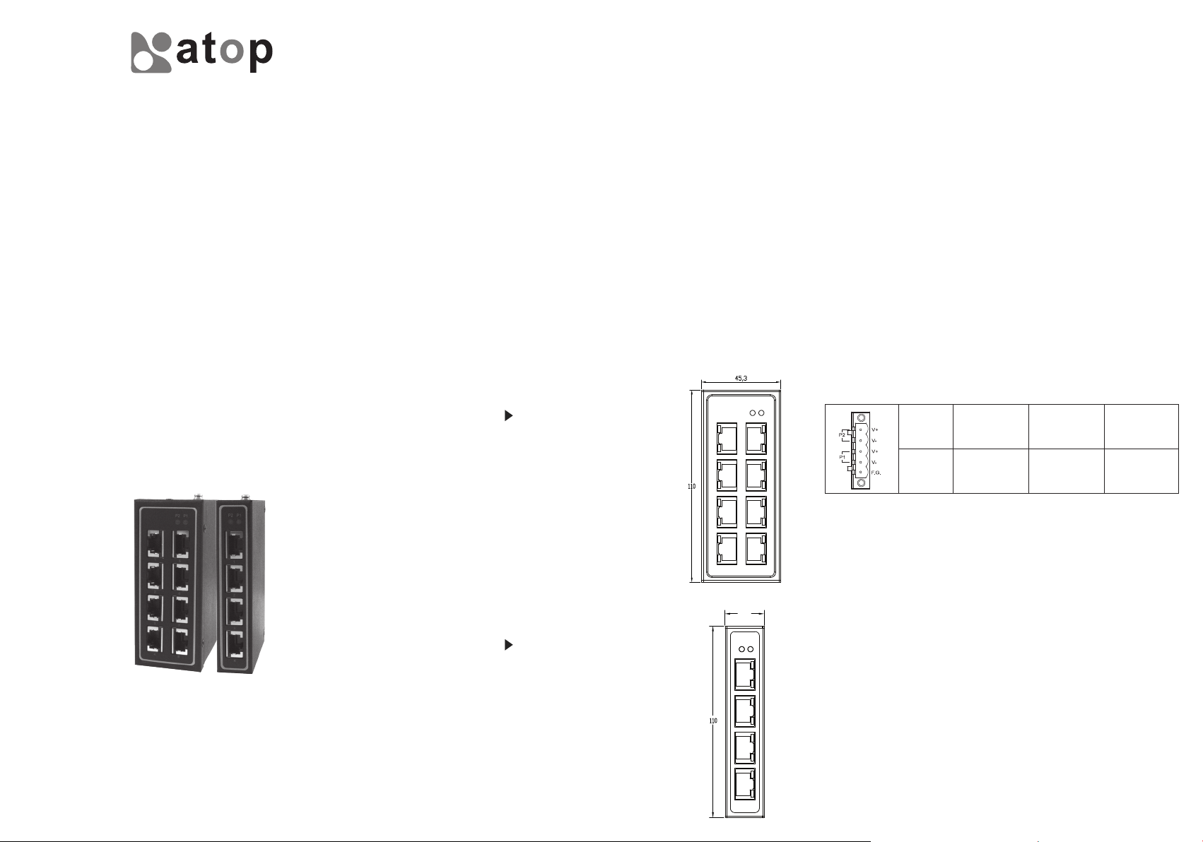
EH2308-PR
8-Port Unmanaged Fast Ethernet Switch
■ 8-port of 10/100Base-TX with RJ-45 connector
Hardware Installation
Step1: Installation on “DIN-Rail”
■ All EH2308-PR and EH2304-PR Switches are equipped with a
DIN-Rail bracket attached onto the rear panel. Please follow the
below steps to fasten the switch to the DIN-Rail correctly.
■ Tip the switch forward and press it against the DIN-Rail after align
the bracket springs to the DIN-Rail.
■ Press the bracket against the upper ledge of the DIN-Rail until it
clicks.
Notice: The EH2308-PR and EH2304-PR Switches are designed to
be mounted on a well-grounded place, such as a metal panel.
Step2: Connecting the Power
■ Prepare the suitable power source and connect it into EH Switch by
Terminal Blocks (TB5).
■ DC 9 - 48V for EH2308-PR and EH2304-PR switche product.
■ You can connect two DC inputs for EH2308-PR and EH2304-PR
switch power if auto-backup needed.
■ Check P1/P2 power LED. The LED(s) will be lighted when the
device is ready.
5-pin Terminal Block for Power Input
Pin
Signal
V+
DC9 - 48V
V-
0V
F.G.
Frame Ground
Tel: 886-3-5508137
Fax: 886-3-5508131
www.atop.com.tw
EH2304-PR
4-Port Unmanaged Fast Ethernet Switch
■ 4 ports of 10/100Base-TX with RJ-45 connector
22.50
Warning: Before connecting EH2308-PR and EH2304-PR Switches
to the DC power input, please make sure the DC voltage supplied by
the power source is correct and stable.
Step3: Connecting the Network Devices
■ Connect your devices using standard UTP/STP cable with RJ-45
connectors to EH2308-PR and EH2304-PR switch. (For the cable
wiring diagrams, please refer to section 7)
■ The corresponding RJ-45 LED will be lighted if the Ethernet
connection is linked successfully.
■ The LED will be blinked during data transfer by EH2308-PR and
EH2304-PR switch.
※ Equipment intended for installation in Restricted Access Location
※ UL Notice for Power supplier
All the series of EH products are intended to be supplied by a Listed
Power Source.
Page 2
LED Indicators
There are four LED indicators located at the front panel of EH series.
Name
P1/P2
RJ-45
LED
Green
Green
Yellow
Status
Off
On
Off
On
Blink
Off
On
Power input 1/2 is not plugged yet
Power status is ready
Link is broken, or no cable is plugged in
The Port is linked
The device is transferring data through the port
The link is operating at rate of 10 Mbps
The link is operating at rate of 100 Mbps
Description
Configuration and Setting Methods
Any settings or configurations are unnecessary.
Pin Assignment of Network Connections
RJ-45(8-pin) to RJ-45(8-pin) straight-through cable wiring
1 8
Cable
10/100BaseT(X) Ethernet Port Connection
RJ-45
Pin
Signal
1 2 3 4 5 6 7 8
Tx+ T x - R x + Rx-
RJ45(8-pin) to RJ45(8-pin) cross-over cable wiring
10/100BaseT(X) Ethernet Port Connection
1 8
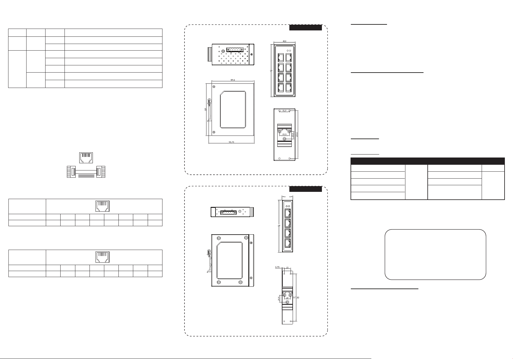
Mechanical dimensions (unit=mm)
EH2308-PR
Top view
Front view
Side view
Rear view
EH2304-PR
22.50
Top view
Warranty Policy
Warranty Conditions
Products supplied by Atop Technologies are covered in this warranty for sub-standard
performance or defective workmanship. The warranty is not, however, extended to goods
damaged in the following circumstances:
(a) Excessive forces or impacts
(b) War or an Act of God: wind storm, fire, flood, electric shock, earthquake
(c) Use of unqualified power supply, connectors, or maintenance procedure
(d) Replacement with unauthorized parts
RMA and Shipping Costs Reimbursement
Customers shall always obtain an authorized "RMA" number from Atop before shipping the
goods to be repaired to Atop. When in normal use, a sold product shall be replaced with a new
one within 3 months after purchase. The shipping cost from the customer to Atop will be
reimbursed by Atop.
After 3 months and still within the warranty period, it is up to Atop whether to replace the unit
with a new one; normally, as long as a product is under warranty, all parts and labor are free of
charge to the customers.
After the warranty period, the customer shall cover the cost for parts and labor.Three months
after purchase, the shipping cost from the customer to Atop will not be reimbursed, but the
shipping cost from Atop to the customer will be paid by Atop.
Limited Liab ility
Atop shall not be held responsible for any consequential losses from using Atop’s product.
Warranty Period
Product Cate gories
Ethernet Swi tches
Wireless
Serial Devic e Servers
Modbus Gatew ays
Embedded Dev ice Servers
The warranty certification will not be effective until an authorized stamp issued by
Atop’s overseas agents.
Purchase Date: / / (yyyy/mm/dd)
Serial Number:
Warranty
5 Years
Product Cate gories
DIN-Rail Pow er Supplies
Power Adaptors
Antennas
Other Accessories
Warranty
3 Years
1 Year
RJ-45
Pin
Signal
1 8
1 2 3 4 5 6 7 8
Rx+ R x - Tx + Tx-
Side view
Front view
Rear view
Atop Custome r Services a nd Supports
1. Please contact your local dealers or Atop Technical Support Center at the
following numbers.
+ 886-3-550-8137 (Atop Taiwan)
+ 86-21-6495-6232 (Atop China)
2. Please report the defected problems via Atop’s Web site or E-mail account
Web Site:www.atop.com.tw, e-mail:service@atop.com.tw
Web Site:www.atop.com.cn, e-mail:service@atop.com.cn
─ Any change by website in material announcement primarily. ─
 Loading...