

Page 1
Atop Technologies, Inc.
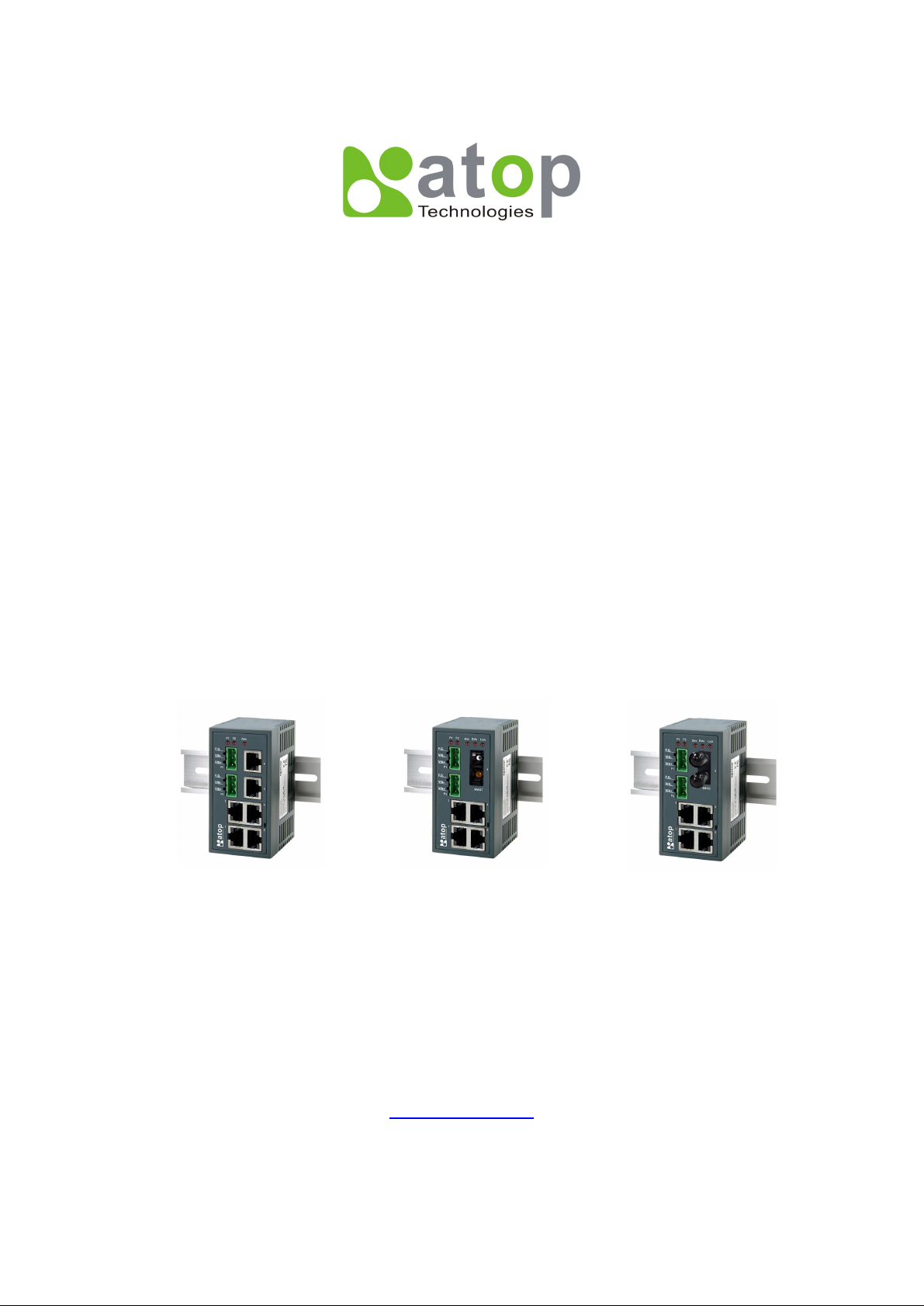
Industrial DIN-Rail Unmanaged Ethernet Switch
EH2006
EH2005-Fs
EH2005-Fm
5/6-port Industrial Unmanaged Ethernet Switch
Hardware Installation Guide
Version 1.4
Updated on March 5, 2012
EH2006
EH2005-Fs
Tel: 886-3-5508137
Fax: 886-3-5508131
www.atop.com.tw
EH2005-Fm
Page 2
Atop Industrial Unmanaged Ethernet Switch
EH2006 / EH2005-Fs / EH2005-Fm
Hardware Installation Guide Version 1.4
1. Introduction
Thank you for purchasing Atop EH-series Indusial Ethernet Switch.
This document intends to provide customers with brief descriptions about
the product and to assist our customers to get started using our devices.
2. Inside the Package
-Main Product
EH2005-Fs/Fm or EH2006 Device
- Standard Accessories
Terminal Block for Power input x2
Hardcopy of EH series Quick Installing Guide x 1
- Optional Accessories
US315-12(US), AC100~240V 50/60HZ 12V/1.25A, US Plug (optional)
US315-12(EU), AC100~240V 50/60HZ 12V/1.25A, EU Plug (optional)
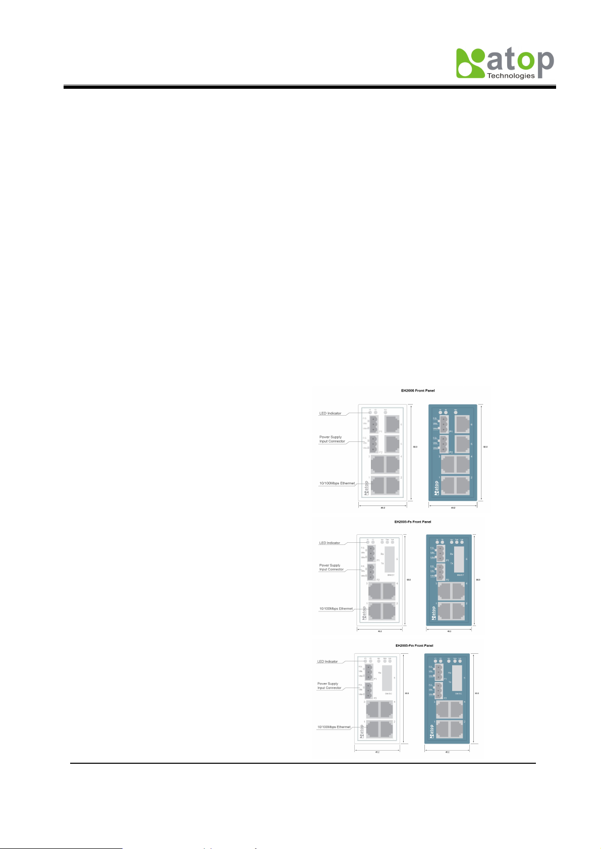
3. Product outline
EH2006
The EH2006 supports six 10/100
base-TX Fast Ethernet connections
with RJ-45 connectors
EH2005-Fs
The EH2005-Fs supports four
10/100 base-TX Fast Ethernet with
RJ45 connectors and one
100Base-FX single-mode Fiber
connection with SC connector
EH2005-Fm
The EH2005-Fm supports four
10/100 base-TX Fast Ethernet with
RJ-45 connectors and one
100Base-FX multi-mode Fiber
connection with ST connector
Copyright c 2010 ATOP Technologies, Inc.
All rights reserved
- 1 -
Page 3

Atop Industrial Unmanaged Ethernet Switch
EH2006 / EH2005-Fs / EH2005-Fm
Hardware Installation Guide Version 1.4
4. Hardware Installation
Step1: Connect to Power
Prepare suitable DC 9~30V power source and connected to EH switch by 3-pin
Terminal blocks.
You can connected two DC input for power auto-backup need.
Check P1/P2 LED for correct power source, everything is OK if the LED(s) was
lighted
Step2: Connect to Network Device by Ethernet
Connected your device by standard UTP/STP cable with RJ-45 connectors to EH
switch.
The LINK LED will be lighted if the Ethernet connection was linked.
It is indicated and blinked if data was transfer by EH switch hub.
UL Notice for Power supplier
All the series of EH products are intended to be supplied by a Listed Power Unit
marked with ¡LPS¡, ¡Limited Power Source¡ or ¡Class 2¡ and output rate 9-30VDC,
0.6A. Or, use the recommended power supply in ¡Optional Accessories.
5. LED Indicators
There are four LED indicators located at the front panel of EH series.
Name LED Status
Off Both P1 and P2 on or off
ALM Green
On Either P1 or P2 on
Off Power input 1/2 is not plugged yet
P1/P2 Green
On Power status is Ready
Off Link is Boren or Cable not be plugged
Green
Blink Traffic be indicted for data transfer
RJ45
Off 10M rate be active
Yellow
On 100M rate be active
Off No data be transmitted
Data
Fiber
SC/ST
Blink Working when data transmitted
Off No media be available
Link
On Working when media was ready
Description
7. Configuration and Setting Methods
Any settings or configurations are unnecessary.
Copyright c 2010 ATOP Technologies, Inc.
All rights reserved
- 2 -
Page 4

Atop Industrial Unmanaged Ethernet Switch
B
A
B
A
EH2006 / EH2005-Fs / EH2005-Fm
Hardware Installation Guide Version 1.4
8. Pin assignment of Network Connections
10/100BaseT(X) Ethernet Port Connection
RJ-45
Pin 1 2 3 4 5 6 7 8
Signal
Tx+ Tx- Rx+
100BaseFx Fiber Cable Wring
-SC/ST Connectors
SC Connectors ST Connecters
Fiber port
Rx-
Single-Mode Multi-mode
-Cable Wiring
ST Connector
TX
RX
A
B
SC Connector
TX
RX
A
B
Terminal Block for Power input
FGVin-Vin+
Pin Vin+ Vin- FG
Signal
DC9-30V 0V Frame Ground
RX
TX
RX
TX
9. ATOP Customer Services and Supports
1. Please contact your local dealers or Atop Technical Support Center at the following
numbers.
+886-3-550-8137 (Atop Taiwan)
+86-21-6495-6232 (Atop China)
2. Please report the defected problems via Atop¡s Web site or E-mail account
Web Site:www.atop.com.tw, e-mail: service@atop.com.tw
Web Site:www.atop.com.cn, e-mail: service@atop.com.cn
Copyright c 2010 ATOP Technologies, Inc.
All rights reserved
- 3 -
 Loading...