

Page 1
Techn olo gie s
Atop Technologies, Inc.
Industrial Ethernet to Fiber Media Convertor
EF23 Series
10/100 Base-TX to 100Base-Fx Media Converters
EF23G Series
1000Base-TX to 1000Base-FX Media Converters
Hardware Installation Guide
Version 1.1
Updated on Dec, 2011
Tel: 886-3-5508137
Fax: 886-3-5508131
www.atop.com.tw
Introduction
Thank you for choosing the Atop Industrial DIN-Rail Ethernet to
Fiber Media Converter. The EF23/EF23G Series provide industrial
grade media conversion between 10/100Base-TX and
100Base-FX (SC connectors)/1000base-T(X) and
1000Base-FX(SC connectors/SFP).
This Guide covers Five product models:
EF23 Series
■
EF23-1-Fm-SC-2:
Fast Ethernet 10/100Base-TX to 100Base-FX Media Converter
with extended operating temperature.
Include 1 10/100M RJ45 and 1 100M Multi-mode Optical Fiber.
■
EF23-1-Fs-SC-30:
Fast Ethernet 10/100Base-TX to 100Base-FX Media Converter
with extended operating temperature.
Include 1 10/100M RJ45 and 1 100M Single-mode Optical Fiber.
EF23G Series
■
EF23-1G-1Fm-SC-500M:
Gigabit Ethernet 1000Base-TX to 1000Base-FX Media Converter
with extended operating temperature.
Include 1 1000M RJ45 and 1 1000M Multi-mode Optical Fiber.
■
EF23-1G-1Fs-SC-10:
Gigabit Ethernet 1000Base-TX to 1000Base-FX Media Converter
with extended operating temperature.
Include 1 1000M RJ45 and 1 1000M Single-mode Optical Fiber.
■
EF23-1G-1SFP:
Gigabit Ethernet 1000Base-TX to 1000Base-SX/LX/LHX Media
Converter with extended operating temperature.
Include 1 1000M RJ45 and 1 1000M SFP slot.
Never install or work on electrical or cabling during
periods of lighting activity. Never connect or disconnect
power when hazardous gases are present.
WARNING:
Disconnect the power and allow to cool 5 minutes
before touching.
Caution:
CLASS 1 LASER PRODUCT. Do not stare into the laser!
This device complies with Part 15 of the FCC Rules. Operation is
subject to the following two conditions:
(1) this device may not cause harmful interference, and
(2) this device must accept any interference received; including
interference that may cause undesired operation.
Inside the Package
■
Main Product
■
Atop EF23/EF23G industrial Ethernet Media Converter x1
■
Standard accessories
■
3-pin Terminal Block (2ESDVM-03P) x1
Atop P/N: 50706701G
■ RJ-45 Port Plugs x1
Atop P/N: 3990012G
■ Hardware Installation Guide (Warranty card is include) x1
Atop P/N: 89900403G
Optional Accessories
■
3-pin Terminal Block(2ESDVM-03P )
Atop P/N: 50706701G
■
Adapter : 3-pin Terminal block (5.08 mm) power adaptor,
100-240VAC input, 1.25A @ 12VDC output, US
plug
Atop P/N: 70100000000027G
■
Adapter : 3-pin Terminal block (5.08 mm) power adaptor,
100-240VAC input, 1.25A @ 12VDC output, EU
plug
Atop P/N: 70100000000028G
Product Description
EF23 Series
1. TX Port: 10/100 Base-TX
2. Green: PWR SPD LED
3. Green: TX_LINK/ACT TX_FDX/COL LED
4. Green: FX_LINK/ACT FX_FDX/COL LED
5. FX Port: 100 Base-FX (SC Connector)
EF23G Series
1. TX Port: 1000 Base-TX
2. Green: ACT TX_LINK
3. Green: PWR FX_FDX/COL LED
4. FX Port: 1000 Base-FX
(SC Connector or SFP Solt)
Hardware Installation
■
Electrical
Step 1: Unpack the Media Converter, check
to make sure no external damages.
Step 2: Connect the power jack with the power
adapter. It is normal to see the PWR
indicator on.
Step 3: Hook up one RJ-45 port to your LAN, and
other port to your computer. Check to mark
sure your host computer can access the LAN.
Step 4: Hook up one FIBER port to other
EF23 series, It is normal to see
the FX_LINK/ACT indicator on.
■
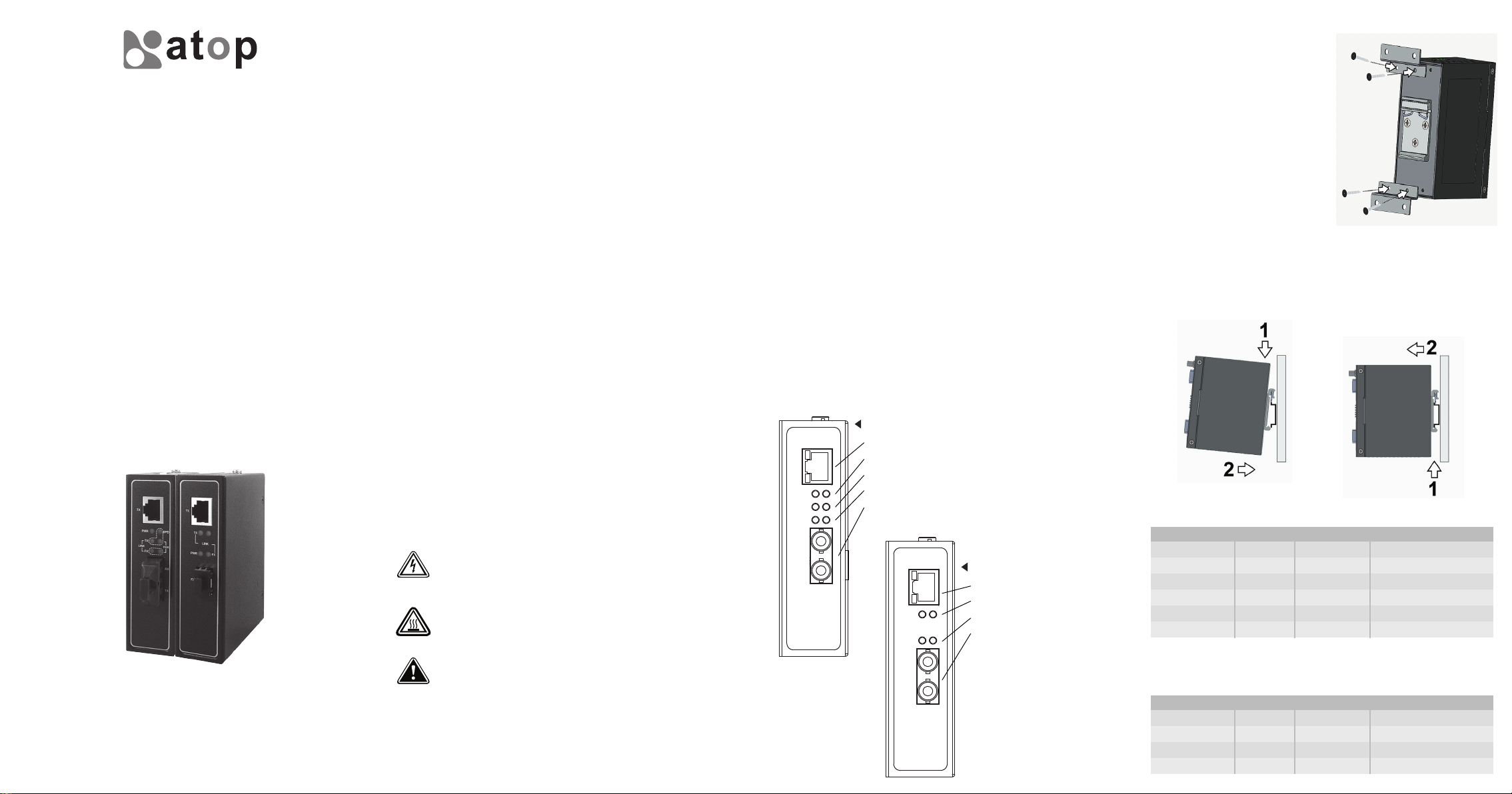
Mechanical
Media Converters are equipped with DIN-Rail bracket attached onto rear
panel. Follow the steps below to fasten the Media Converter to DIN-Rail.
Step 1: Tilt the unit slightly backwards.
Step 2: Fit the unit over top the DIN-Rail.
Step 3: Push downwards and against the DIN-Rail for locking.
Step 4: Check that the unit is locked into position.
EF23 Series LED Indicators
LED
PWR
SPD
TX_LINK\ACT
TX_FDX/COL
FX_LINK\ACT
FX_FDX/COL
* SPD only for TX
ON
ON
100M
Link up
Full
Link up
Full
OFF
OFF
10M
Link down
Half
Link down
Half
Flash
Link up/Active
Half/Col happen
Link up/Active
Half/Col happen
EF23G Series LED Indicators
LED
ACT
TX_LINK\ACT
PWR
FX_LINK\ACT
ON
Link up
ON
Link up
OFF
Link down
OFF
Link down
Flash
Transmitting or Receiving
PWR
Link up/Active
Page 2

Pin Assignment of Network Connections
10/100 Base-TX Ethernet Port Connection
RJ-45
10/100/1000 Base –TX
Pin
Signal
Cable type, Max. Transmission and Connection
Speed
10 Base-T
100 Base-T
1000 Base-T
100 Base-F
1000 Base-SX
1000 Base-LX\LHX
1000 Base-SX\SX+
1000 Base-LX\LHX
100/1000Base-Fx Fiber SC Cable Wiring
1
Tx+2Tx-3Rx+4NC1+5NC1-6Rx-7NC2+8NC2-
Cable
Cat. 3,4,5
Cat. 5 UTP
Cat. 5/Cat.5e UTP
850nm,1310nm,
Multi-mode
850nm,1310nm,
Multi-mode
1310nm,Single-mode
850nm,1310nm,
Multi-mode
1310nm,1550nm,
Single-mode
SC Connectors ST Connectors
Tx
Fiber Port
Rx
Single-mode Multi-mode
1 8
Max. Length
UTP 100m
(328 ft)
UTP 100m
(328 ft)
UTP 100m
(328 ft)
2km
500m
30km
2km
30km
Connector
RJ-45
RJ-45
RJ-45
SC
SC
SC
SFP
SFP
Tx
Rx
3-pin Terminal Block for power input
EF23 Series EF23G Series
7 6 5 4 3 2 1 6 5 4 3 2 1
1. Grounding screw
2. LOCK
3. Frame Ground
4. V-
5. V+
6. LOCK
7. DIP Switch
1. Grounding screw
2. LOCK
3. Frame Ground
4. V-
5. V+
6. LOCK
Mechanical dimensions(unit=mm)
Front view-EF23 Series
10/10 0Base TX (copp er)
100Ba se FX (SC conn ector )
1000B ase FX (SC or SFP s lot)
Back view Side view and Panel Mounting View
Front view-EF23G Series
Warranty Policy
Warranty Conditions
Products supplied by Atop Technologies are covered in this warranty for
sub-standard performance or defective workmanship. The warranty is
not, however, extended to goods damaged in the following
circumstances:
(a) Excessive forces or impacts
(b) War or an Act of God: wind storm, fire, flood, electric shock,
earthquake
(c) Use of unqualified power supply, connectors, or maintenance
procedure
(d) Replacement with unauthorized parts
RMA and Shipping Costs Reimbursement
Customers shall always obtain an authorized "RMA" number from Atop
before shipping the goods to be repaired to Atop. When in normal use,
a sold product shall be replaced with a new one within 3 months after
purchase. The shipping cost from the customer to Atop will be
reimbursed by Atop.
After 3 months and still within the warranty period, it is up to Atop
whether to replace the unit with a new one; normally, as long as a
product is under warranty, all parts and labor are free of charge to the
customers.
After the warranty period, the customer shall cover the cost for parts
and labor.Three months after purchase, the shipping cost from the
customer to Atop will not be reimbursed, but the shipping cost from
Atop to the customer will be paid by Atop.
Limited Liability
Atop shall not be held responsible for any consequential losses from
using Atop’s product.
The warranty certification will not be effective until an authorized stamp
issued by Atop’s overseas agents.
Purchase Date: / / (yyyy/mm/dd)
Serial Number:
100/1000Base-Fx Fiber SC Cable Wiring
ST Connector
TX
RX
A
B
←→
←→
SC Connector
TX
RX
A
B
←→
←→
Warranty Period
Product Categories
Warranty
Ethernet Switches
Wireless
Serial Device Servers
5 Years
Modbus Gateways
B
A
B
A
RX
TX
RX
TX
Top view-EF23 Series Top view-EF23G Series
Redund ant inputs Powe r Sup ply (6/12 /24/4 8)
Embedded Device Servers
DIN-Rail Power Supplies
Power Adaptors
Antennas
Other Accessories
3 Years
1 Year
ATOP Customer Services and Supports
1. Please contact your local dealers or Atop Technical Support Center at
the following numbers.
+ 886-3-550-8137 (Atop Taiwan)
+ 86-21-6495-6232 (Atop China)
2. Please report the defected problems via Atop’s Web site or E-mail
account
Web Site:www.atop.com.tw, e-mail:service@atop.com.tw
Web Site:www.atop.com.cn, e-mail:service@atop.com.cn
─ Any change by website in material announcement primarily. ─
 Loading...