

Page 1

Industrial Managed
Ethernet Switch
User Manual
Series covered by this manual:
EHG75XX, RHG75XX*, EHG95XX*, EMG85XX*, EH75XX*
* The user interface on these products may be slightly different
from the one shown on this user manual
Atop Technologies, Inc.
Industrial Managed
Ethernet Switch
User Manual
March 22nd, 2017
Page 1 of 190
V1.3
Page 2

Industrial Managed
Ethernet Switch
User Manual
This PDF Document contains internal hyperlinks for ease of navigation.
For example, click on any item listed in the Table of Contents to go to that page.
Published by:
Atop Technologies, Inc.
2F, No. 146, Sec. 1, Tung-Hsing Rd,
30261 Chupei City, Hsinchu County
Taiwan, R.O.C.
Tel: +886-3-550-8137
Fax: +886-3-550-8131
www.atoponline.com
www.atop.com.tw
Page 2 of 190
Page 3

Industrial Managed
Ethernet Switch
User Manual
Author:
Matteo Tabarelli
Revision:
1.3
Revision History:
New format, new features, new default password
Creation Date:
07 June 2016
Last Revision Date:
29 March 2017
Product Reference:
Layer-2 Managed Switch
Document Status:
Released
Important Announcement
The information contained in this document is the property of Atop Technologies, Inc., and is supplied for the sole
purpose of operation and maintenance of Atop Technologies, Inc., products.
No part of this publication is to be used for any other purposes, and it is not to be reproduced, copied, disclosed,
transmitted, stored in a retrieval system, or translated into any human or computer language, in any form, by any
means, in whole or in part, without the prior explicit written consent of Atop Technologies, Inc.,
Offenders will be held liable for damages and prosecution.
All rights, including rights created by patent grant or registration of a utility model or design, are reserved.
Disclaimer
We have checked the contents of this manual for agreement with the hardware and the software described. Since
deviations cannot be precluded entirely, we cannot guarantee full agreement. However, the data in this manual is
reviewed regularly and any necessary corrections will be included in subsequent editions.
Suggestions for improvement are welcome. All other product’s names referenced herein are registered trademarks
of their respective companies.
Preface
This manual contains some advanced network management knowledge, instructions, examples, guidelines, and
general theories. The contents are designed to help users manage the switch and use its software, a background
in general theory is a must, when reading it. Please refer to the Glossary for technical terms and abbreviations.
Who Should Use This User Manual
This manual is to be used by qualified network personnel or support technicians who are familiar with network
operations, and might be useful for system programmers or network planners as well. This manual also provides
helpful and handy information for first time users. For any related problems, please contact your local distributor.
If they are unable to assist you, please redirect your inquiries to www.atop.com.tw.
Warranty Period
Atop technology provides a limited 5-year warranty for managed Ethernet switches.
Documentation Control
Page 3 of 190
Page 4

Industrial Managed
Ethernet Switch
User Manual
Table of Contents
1 Introduction ............................................................................................................... 13
1.1 Introduction to Industrial Managed Switch ..................................................................................... 13
1.2 Software Features .......................................................................................................................... 14
2 Configuring with a Web Browser ................................................................................ 15
2.1 Web-based Management Basics ................................................................................................... 15
2.1.1 Default Factory Settings ................................................................................................................. 15
2.1.2 Login Process and Main Window Interface .................................................................................... 16
2.2 Basic Information ............................................................................................................................ 17
2.2.1 Sys Info ........................................................................................................................................... 17
2.2.2 Device Information Setting ............................................................................................................. 18
2.2.3 Console Setting .............................................................................................................................. 19
2.2.4 Protocols Status ............................................................................................................................. 19
2.2.5 Power Status .................................................................................................................................. 20
2.2.6 Temperature Log ............................................................................................................................ 20
2.3 Administration ................................................................................................................................. 22
2.3.1 Password........................................................................................................................................ 22
2.3.2 IP Setting ........................................................................................................................................ 24
2.3.3 IPv6 Setting .................................................................................................................................... 27
2.3.4 Ping ................................................................................................................................................ 29
2.3.5 Ping6 .............................................................................................................................................. 30
2.3.6 Mirror Port ...................................................................................................................................... 31
2.3.7 System Time................................................................................................................................... 32
2.3.8 Modbus Setting .............................................................................................................................. 33
2.3.9 Precision Time Protocol (PTP) ....................................................................................................... 41
2.3.10 Secure Shell - SSH .......................................................................................................................... 44
2.3.11 Telnet.............................................................................................................................................. 45
2.3.12 DIP Switch ...................................................................................................................................... 45
2.4 Forwarding ..................................................................................................................................... 46
2.4.1 QoS ................................................................................................................................................. 46
2.4.2 Rate Control .................................................................................................................................... 50
2.4.3 Storm Control ................................................................................................................................. 51
2.5 Port-related settings ....................................................................................................................... 53
2.5.1 Port Setting ..................................................................................................................................... 54
2.5.2 Port Status ...................................................................................................................................... 55
2.5.3 Mini-GBIC Port Status .................................................................................................................... 56
2.5.4 Port Statistics ................................................................................................................................. 56
2.6 Power over Ethernet....................................................................................................................... 58
2.6.1 PoE Setting ..................................................................................................................................... 58
2.6.2 PoE Status ...................................................................................................................................... 59
2.6.3 PoE Alarm Setting .......................................................................................................................... 60
2.7 Trunking ......................................................................................................................................... 61
2.7.1 Trunking Setting ............................................................................................................................. 61
2.7.2 LACP Status ................................................................................................................................... 63
2.8 Unicast/Multicast MAC ................................................................................................................... 65
2.8.1 Add Static MAC .............................................................................................................................. 66
2.8.2 Black-List MAC ............................................................................................................................... 67
2.8.3 MAC Aging Time ............................................................................................................................ 67
Page 4 of 190
Page 5

Industrial Managed
Ethernet Switch
User Manual
2.8.4 MAC Table ...................................................................................................................................... 68
2.9 GARP/GVRP/GMRP ...................................................................................................................... 70
2.9.1 Multicast Group Table .................................................................................................................... 70
2.9.2 GARP Setting .................................................................................................................................. 71
2.9.3 GVRP Setting .................................................................................................................................. 72
2.9.4 GMRP Setting ................................................................................................................................. 73
2.10 IP Multicast ..................................................................................................................................... 74
2.10.1 IGMP ............................................................................................................................................... 75
2.10.2 Static IP Multicast .......................................................................................................................... 80
2.11 SNMP ............................................................................................................................................. 81
2.11.1 SNMP Agent ................................................................................................................................... 82
2.11.2 SNMP V1/V2c Community Setting ................................................................................................. 83
2.11.3 Trap Setting .................................................................................................................................... 84
2.11.4 SNMPv3 Auth. Setting .................................................................................................................... 84
2.12 Spanning Tree ................................................................................................................................ 86
2.12.1 Spanning Tree Setting .................................................................................................................... 87
2.12.2 Bridge Info ...................................................................................................................................... 89
2.12.3 Port Setting ..................................................................................................................................... 90
2.12.4 MSTP Instance ............................................................................................................................... 93
2.13 VLAN .............................................................................................................................................. 94
2.13.1 VLAN Setting .................................................................................................................................. 95
2.13.2 802.1Q VLAN .................................................................................................................................. 96
2.13.3 Port-Based VLAN ........................................................................................................................... 99
2.13.4 MAC-Based VLAN ........................................................................................................................ 100
2.13.5 IP Subnet-Based VLAN ................................................................................................................. 100
2.13.6 Protocol-Based VLAN................................................................................................................... 101
2.13.7 QinQ .............................................................................................................................................. 102
2.14 Security ........................................................................................................................................ 104
2.14.1 Port Security ................................................................................................................................. 104
2.14.2 802.1X .......................................................................................................................................... 106
2.14.3 ACL ............................................................................................................................................... 110
2.15 ERPS Ring ................................................................................................................................... 113
2.15.1 ESRP Setting ................................................................................................................................. 114
2.15.2 iA-Ring Settings ............................................................................................................................ 119
2.15.3 C-Ring (Compatible-Ring) Settings .............................................................................................. 121
2.15.4 U-Ring ........................................................................................................................................... 121
2.15.5 Compatible-Chain Settings........................................................................................................... 124
2.16 LLDP............................................................................................................................................. 127
2.16.1 LLDP Settings ............................................................................................................................... 127
2.16.2 LLDP Neighbors............................................................................................................................ 128
2.17 PROFINET ................................................................................................................................... 130
2.17.1 PROFINET Settings ....................................................................................................................... 130
2.17.2 PROFINET’s I&M ........................................................................................................................... 131
2.17.3 PROFINET MRP ............................................................................................................................ 131
2.18 EtherNet/IP ................................................................................................................................... 135
2.18.1 EtherNet/IP Settings ..................................................................................................................... 136
2.19 Client IP Setting ............................................................................................................................ 136
2.19.1 DHCP Relay Agent ........................................................................................................................ 136
2.19.2 DHCP Mapping IP ......................................................................................................................... 137
2.20 System ......................................................................................................................................... 138
2.20.1 System Log ................................................................................................................................... 139
2.20.2 Warning/Alarm .............................................................................................................................. 140
Page 5 of 190
Page 6

Industrial Managed
Ethernet Switch
User Manual
2.20.3 Denial of Service ........................................................................................................................... 146
2.20.4 Backup/Restore Config. ................................................................................................................ 147
2.20.5 Firmware Update .......................................................................................................................... 151
2.20.6 Factory Default Setting ................................................................................................................. 151
2.20.7 Reboot .......................................................................................................................................... 151
3 Configuring with a Serial Console ............................................................................ 152
3.1 Serial Console Setup.................................................................................................................... 152
3.2 Command Line Interface Introduction .......................................................................................... 153
3.3 General Commands ..................................................................................................................... 154
3.4 Command Example ...................................................................................................................... 155
3.4.1 Administration Setup using Serial Console .................................................................................. 155
3.4.2 Spanning Tree Setup using Serial Console................................................................................... 156
4 Configuring with a Telnet Console ........................................................................... 157
4.1 Telnet ........................................................................................................................................... 157
4.2 Telnet Log-in ................................................................................................................................ 157
4.3 Command Line Interface for Telnet .............................................................................................. 157
4.4 Commands in the Privileged Mode .............................................................................................. 158
4.5 Commands in the Configuration Mode ......................................................................................... 158
5 Device Management Utility ...................................................................................... 161
5.1 Network Setting ............................................................................................................................ 162
5.2 Topology Diagram ........................................................................................................................ 163
5.3 Firmware Update .......................................................................................................................... 165
6 Glossary .................................................................................................................. 166
7 Modbus Memory Map ............................................................................................. 168
8 CIP supported objects of Ethernet/IP ...................................................................... 177
8.1 Identity Object .............................................................................................................................. 177
8.2 TCP/IP Interface Object ............................................................................................................... 178
8.3 Ethernet Link Object ..................................................................................................................... 180
8.4 Assembly Object .......................................................................................................................... 184
8.5 Message Router Object (Not supported) .................................................................................... 185
8.6 Connection Manager Object ........................................................................................................ 186
8.7 Port Object ................................................................................................................................... 187
Table of Figures
Figure 2.1 IP Address for Web-based Setting .............................................................................................................. 16
Figure 2.2 Default Web Interface .................................................................................................................................. 16
Figure 2.3 Basic Information Dropdown Menu ............................................................................................................ 17
Figure 2.4 Details of Sys Info Webpage ........................................................................................................................ 17
Figure 2.5 Details of Device Information Settings Webpage....................................................................................... 18
Figure 2.6 Setting Parameters for the Console Method .............................................................................................. 19
Figure 2.7 Protocol Status Webpage ............................................................................................................................ 19
Figure 2.8 Power Status Webpage ................................................................................................................................ 20
Page 6 of 190
Page 7

Industrial Managed
Ethernet Switch
User Manual
Introduction
Figure 2.9 User Temperature Log ................................................................................................................................. 21
Figure 2.10 System Temperature Log .......................................................................................................................... 21
Figure 2.11 Administration Dropdown Menu ............................................................................................................... 22
Figure 2.12 Password Setting Webpage ...................................................................................................................... 22
Figure 2.13 Authentication Server Setting .................................................................................................................... 23
Figure 2.14 IP Setting under IP Setting Webpage ........................................................................................................ 25
Figure 2.15 IP Interface Part under IP Setting Webpage ............................................................................................. 25
Figure 2.16 IPv6 Setting Part of IPv6 Setting Webpage .............................................................................................. 27
Figure 2.17 Current IPv6 Address Information Part of IPv6 Setting Page .................................................................. 27
Figure 2.18 IP Interface for IPv6 Part of IPv6 Setting Webpage ................................................................................. 28
Figure 2.19 Ping Webpage............................................................................................................................................. 29
Figure 2.20 Example of Ping Command ....................................................................................................................... 29
Figure 2.21 Example of successful ping command result .......................................................................................... 29
Figure 2.22 Example of unsuccessful ping command result ...................................................................................... 30
Figure 2.23 Ping6 Webpage .......................................................................................................................................... 30
Figure 2.24 Example of Successful Ping6 Result ........................................................................................................ 30
Figure 2.25 Mirror Port Webpage .................................................................................................................................. 31
Figure 2.26 Webpage for Setting System Time and SNTP .......................................................................................... 32
Figure 2.27 Webpage for Setting the Modbus Address ............................................................................................... 33
Figure 2.28 Mapping Table of Modbus Address for Switch’s IP Address .................................................................. 34
Figure 2.29 Entering Connection Setup Menu of the Modbus Poll ............................................................................. 34
Figure 2.30 Modbus Poll Connection Setup ................................................................................................................. 35
Figure 2.31 Mulitple Cell Section in Modbus Poll ......................................................................................................... 35
Figure 2.32 Set Display Mode to Hex in Modbus Poll .................................................................................................. 36
Figure 2.33 Modbus Poll Setup Read/Write Definition ................................................................................................. 36
Figure 2.34 Slave ID in the Modbus Poll Function is set to 1 ...................................................................................... 37
Figure 2.35 Set Code 03 in the Modbus Poll Function ................................................................................................. 37
Figure 2.36 Setup Starting Address and Quantity in Modbus Poll .............................................................................. 38
Figure 2.37 Modbus Memory Address 81 and 82 are the location of EHG7508's IP Address .................................. 38
Figure 2.38 Mapping Table of Modbus Address for Clearing Port Statistics............................................................. 39
Figure 2.39 Port Count in Port Statistics Webpage ..................................................................................................... 39
Figure 2.40 Click on Function 06 in the Modbus Poll .................................................................................................. 39
Figure 2.41 Use Modbus Poll to Clear Switch's Port Count ......................................................................................... 40
Figure 2.42 Cleared Port Statistics ............................................................................................................................... 40
Figure 2.43 PTP's Submenu .......................................................................................................................................... 41
Figure 2.44 PTP Setting Webpage, example taken from EH75XX series ................................................................... 42
Figure 2.45 Hardware PTP Setting ................................................................................................................................ 44
Figure 2.46 SSH Setting Webpage ................................................................................................................................ 44
Figure 2.47 Telnet Setting Webpage ............................................................................................................................. 45
Figure 2.48 DIP Switch Status Webpage ...................................................................................................................... 45
Figure 2.49 Forwarding Dropdown Menu ..................................................................................................................... 46
Figure 2.50 QoS Dropdown Menu ................................................................................................................................. 46
Figure 2.51 QoS Setting Webpage ................................................................................................................................ 48
Figure 2.52 Mapping Table of CoS Webpage ............................................................................................................... 49
Figure 2.53 Mapping Table of DSCP and ECN Webpage ............................................................................................. 50
Figure 2.54 Rate Control Webpage ............................................................................................................................... 51
Figure 2.55 Storm Control Webpage ............................................................................................................................. 52
Figure 2.56 Port Dropdown Menu ................................................................................................................................. 53
Figure 2.57 Port Setting Webpage ................................................................................................................................ 54
Figure 2.58 Port Status Webpage ................................................................................................................................. 55
Page 7 of 190
Page 8

Industrial Managed
Ethernet Switch
User Manual
Introduction
Figure 2.59 Mini-GBIC Port Status Webpage ............................................................................................................... 56
Figure 2.60 Port Statistics Webpage ............................................................................................................................ 57
Figure 2.61 Power over Ethernet Dropdown Menu example on EHG7508-4SFP-4PoE ............................................. 58
Figure 2.62 PoE Setting Webpage example on EHG7508-8PoE ................................................................................. 58
Figure 2.63 PoE Status Webpage, example on EHG7508-8PoE .................................................................................. 59
Figure 2.64 PoE Alarm Setting ...................................................................................................................................... 60
Figure 2.65 Trunking Dropdown Menu ......................................................................................................................... 61
Figure 2.66 Trunking Setting Webpage, example with EH7520 .................................................................................. 62
Figure 2.67 LACP Webpage ........................................................................................................................................... 64
Figure 2.68 Unicast vs. Multicast ................................................................................................................................. 65
Figure 2.69 Unicast/Multicast Dropdown Menu ........................................................................................................... 66
Figure 2.70 Add Static MAC Webpage.......................................................................................................................... 67
Figure 2.71 Black-List MAC Setting Webpage ............................................................................................................. 67
Figure 2.72 MAC Aging Time Webpage ........................................................................................................................ 68
Figure 2.73 MAC Table Webpage ................................................................................................................................. 68
Figure 2.74 GARP/GVRP/GMRP Dropdown Menu ........................................................................................................ 70
Figure 2.75 Multicast Group Table ................................................................................................................................ 71
Figure 2.76 GARP Setting Webpage ............................................................................................................................. 71
Figure 2.77 GVRP Setting Box with Port Enabling ....................................................................................................... 72
Figure 2.78 GVRP Statistics .......................................................................................................................................... 72
Figure 2.79 GMRP Setting Box ...................................................................................................................................... 73
Figure 2.80 GMRP Statistics.......................................................................................................................................... 74
Figure 2.81 IP Multicast Dropdown Menu .................................................................................................................... 75
Figure 2.82 IGMP's Options ........................................................................................................................................... 75
Figure 2.83 IGMP Setting Webpage .............................................................................................................................. 76
Figure 2.84 Example of IGMP Proxy ............................................................................................................................. 77
Figure 2.85 IGMP's IP Multicast Table Webpage ......................................................................................................... 77
Figure 2.86 Example of IGMP's IP Multicast Table ...................................................................................................... 78
Figure 2.87 IGMP Statistics Webpage .......................................................................................................................... 78
Figure 2.88 Example of IGMP's Statistics..................................................................................................................... 79
Figure 2.89 Static IP Multicast Setting Webpage ......................................................................................................... 80
Figure 2.90 Example of Static IP Multicast Setting ..................................................................................................... 81
Figure 2.91 SNMP Dropdown Menu .............................................................................................................................. 82
Figure 2.92 SNMP Enabling Box.................................................................................................................................... 82
Figure 2.93 SNMP Community Strings ......................................................................................................................... 83
Figure 2.94 Example of Trap Receiver Setting ............................................................................................................. 84
Figure 2.95 SNMPv3 Users' Options ............................................................................................................................. 85
Figure 2.96 Spanning Tree Dropdown Menu ................................................................................................................ 86
Figure 2.97 Spanning Tree Mode Setting ..................................................................................................................... 87
Figure 2.98 Spanning Tree Main Setting for STP and RSTP ........................................................................................ 87
Figure 2.99 Spanning Tree Main Setting for MSTP ...................................................................................................... 88
Figure 2.100 Spanning Tree Per-port Setting for STP and RSTP ................................................................................ 89
Figure 2.101 Bridge Information Webpage .................................................................................................................. 89
Figure 2.102 Spanning Tree Port Setting Webpage ..................................................................................................... 91
Figure 2.103 MSTP Instance Webpage ........................................................................................................................ 93
Figure 2.104 Example of VLAN Configuration ............................................................................................................. 94
Figure 2.105 VLAN Dropdown Menu............................................................................................................................. 95
Figure 2.106 VLAN Setting Webpage ............................................................................................................................ 95
Figure 2.107 802.1Q VLAN Dropdown Menu ............................................................................................................... 96
Figure 2.108 802.1Q VLAN’s Setting Webpage ............................................................................................................ 97
Page 8 of 190
Page 9

Industrial Managed
Ethernet Switch
User Manual
Introduction
Figure 2.109 802.1Q VLAN PVID Setting Webpage ..................................................................................................... 98
Figure 2.110 802.1Q VLAN Table Webpage ................................................................................................................. 98
Figure 2.111 Example of 802.1Q VLAN Table .............................................................................................................. 99
Figure 2.112 Port-based VLAN Setting Webpage ...................................................................................................... 100
Figure 2.113 MAC-Based VLAN Setting Webpage ..................................................................................................... 100
Figure 2.114 IP Subnet-Based VLAN Setting Webpage ............................................................................................. 101
Figure 2.115 Protocol to Group Setting Webpage ..................................................................................................... 101
Figure 2.116 Group to VLAN Setting Webpage .......................................................................................................... 102
Figure 2.117 Example of QinQ Deployment ................................................................................................................ 102
Figure 2.118 QinQ Setting Webpage ........................................................................................................................... 103
Figure 2.119 Security Dropdown Menu ....................................................................................................................... 104
Figure 2.120 Port Security Setting Webpage .............................................................................................................. 105
Figure 2.121 White-List MAC Webpage ...................................................................................................................... 105
Figure 2.122 RADIUS Authentication Sequence ......................................................................................................... 106
Figure 2.123 802.1X Setting Webpage ....................................................................................................................... 107
Figure 2.124 802.1X's Parameters Setting Webpage ................................................................................................ 108
Figure 2.125 802.1x Port Setting Webpage ................................................................................................................ 109
Figure 2.126 Security Access Control List Information Webpage (MAC Based Filtering) ...................................... 110
Figure 2.127 Security Access Control List Information Webpage (IP Based Filtering) .......................................... 111
Figure 2.128 An Example of Ring Topology (Example made on EH7520) ............................................................... 113
Figure 2.129 ERPS/Ring Drowdown Menu .................................................................................................................. 114
Figure 2.130 ERPS Setting Webpage .......................................................................................................................... 115
Figure 2.131 ERPS RAPS VLAN Setting Webpage ..................................................................................................... 116
Figure 2.132 Example of Ring Topology for ERPS Setup (Example made on EH7520) .......................................... 117
Figure 2.133 Example of Switch A’s ERPS settings ................................................................................................... 118
Figure 2.134 Example of Switch A’s RAPS VLAN Settings........................................................................................ 118
Figure 2.135 Example of Switch B’s RAPS VLAN Setting .......................................................................................... 118
Figure 2.136 Switch A’s ERPS state ............................................................................................................................ 119
Figure 2.137 iA-Ring Example Topology (Example made on EH7520)..................................................................... 119
Figure 2.138 iA-Ring Setting Webpage ....................................................................................................................... 120
Figure 2.139 Compatible-Ring (C-Ring) Setting Webpage ........................................................................................ 121
Figure 2.140 Example 1 of Two Wireless Bridge U-ring (Example made on EH7520)............................................. 122
Figure 2.141 Example 2 of Two Wired Bridge U-ring (Example on EH7520) ............................................................ 123
Figure 2.142 U-Ring Setting Webpage ........................................................................................................................ 124
Figure 2.143 Compatible-Chain Setting Webpage ..................................................................................................... 125
Figure 2.144 LLDP Dropdown Menu ........................................................................................................................... 127
Figure 2.145 LLDP Setting Webpage .......................................................................................................................... 128
Figure 2.146 LLDP Neighbors Webpage ..................................................................................................................... 128
Figure 2.147 Example of LLDP Neighbors Webpage ................................................................................................. 129
Figure 2.148 PROFINET Dropdown Menu ................................................................................................................... 130
Figure 2.149 PROFINET Setting Webpage, example on EH7512 .............................................................................. 131
Figure 2.150 PROFINET I&M ........................................................................................................................................ 131
Figure 2.151 MRP Setting Webpage ........................................................................................................................... 132
Figure 2.152 Example of PROFINET's MRP VLAN Entry ............................................................................................ 133
Figure 2.153 MRP Ring Setting Webpage ................................................................................................................... 133
Figure 2.154 MRP Ring Setting Error Message .......................................................................................................... 134
Figure 2.155 EtherNet/IP Dropdown Menu ................................................................................................................. 135
Figure 2.156 EtherNet/IP Setting Webpage ................................................................................................................ 136
Figure 2.157 Client IP Setting Dropdown Menu ......................................................................................................... 136
Figure 2.158 DHCP Relay Agent Webpage ................................................................................................................. 137
Page 9 of 190
Page 10

Industrial Managed
Ethernet Switch
User Manual
Introduction
Figure 2.159 DHCP Mapping IP Webpage .................................................................................................................. 137
Figure 2.160 System Dropdown Menu ........................................................................................................................ 138
Figure 2.161 System Log Setting Webpage ............................................................................................................... 139
Figure 2.162 Event Log Webpage ............................................................................................................................... 140
Figure 2.163 Webpage of Warning Event Selection ................................................................................................... 141
Figure 2.164 SMTP Setting Webpage ......................................................................................................................... 143
Figure 2.165 Example of SMTP Setting ...................................................................................................................... 144
Figure 2.166 Warning/Alarm Log Webpage ................................................................................................................ 145
Figure 2.167 Example of Warning Events ................................................................................................................... 145
Figure 2.168 Denial of Service Setting Webpage ....................................................................................................... 146
Figure 2.169 Backup/Restore Config. Dropdown Menu ............................................................................................ 148
Figure 2.170 Backup/Restore Configuration via HTTP .............................................................................................. 149
Figure 2.171 Backup/Restore Configuration via TFTP ............................................................................................... 150
Figure 2.172 Firmware Update Webpage ................................................................................................................... 151
Figure 2.173 Factory Default Setting Webpage ......................................................................................................... 151
Figure 2.174 Reboot Webpage .................................................................................................................................... 151
Figure 3.1 Setting of New Connection in Tera Term Program .................................................................................. 152
Figure 3.2 Setup Menu ................................................................................................................................................. 152
Figure 3.3 Setting for the Serial Port ........................................................................................................................... 153
Figure 3.4 Modes, privileges and promts ................................................................................................................... 154
Figure 3.5 Example of Commands .............................................................................................................................. 155
Figure 4.1 Telnet Command ........................................................................................................................................ 157
Figure 4.2 Log-in Screen using Telnet ........................................................................................................................ 157
Figure 4.3 Commands in the Privileged Mode ........................................................................................................... 158
Figure 4.4 Commands in the Configuration Mode ..................................................................................................... 159
Figure 5.1 Device Management Utility ........................................................................................................................ 161
Figure 5.2 Rescan (Search) Icon ................................................................................................................................. 161
Figure 5.3 Authentiction to Login to EHG7XXX switch .............................................................................................. 162
Figure 5.4 Network Configure Icon ............................................................................................................................. 162
Figure 5.5 Network Setting Dialog .............................................................................................................................. 162
Figure 5.6 Administration Verification before Changing the Network Setting ......................................................... 163
Figure 5.7 Warning Dialog before the Device Restart ................................................................................................ 163
Figure 5.8 Topology Diagram ...................................................................................................................................... 164
Figure 5.9 Show Information on Topology Diagram .................................................................................................. 164
Figure 5.10 Upgrade from Disk (Firmware Update) Icon ........................................................................................... 165
Figure 5.11 Dialog Window for Download Firmware from Disk ................................................................................ 165
Table 2.1 Descriptions of the Basic information .......................................................................................................... 18
Table 2.2 Descriptions of the System Settings ............................................................................................................ 18
Table 2.3 Descriptions of Password Setting ................................................................................................................ 23
Table 2.4 Authentication Server Settings ..................................................................................................................... 23
Table 2.5 Comparison of Authentication Server Settings between RADIUS and TACACS+ ..................................... 24
Table 2.6 Descriptions of IP Settings ........................................................................................................................... 26
Table 2.7 Description of IPv6 Setting............................................................................................................................ 28
Table 2.8 Description of Port Mirroring Options .......................................................................................................... 31
Table 2.9 Descriptions of the System Time and the SNTP ......................................................................................... 32
Table 2.10 Description of PTP Setting .......................................................................................................................... 43
Page 10 of 190
Table of Tables
Page 11

Industrial Managed
Ethernet Switch
User Manual
Introduction
Table 2.11 Description of PTP Port Setting ................................................................................................................. 43
Table 2.12 Descriptions of QoS Setting ........................................................................................................................ 47
Table 2.13 Priority queue descriptions ......................................................................................................................... 49
Table 2.14 Descriptions of Rate Control Setting .......................................................................................................... 51
Table 2.15 Descriptions of Storm Control .................................................................................................................... 52
Table 2.16 Descriptions of Limiting Parameters.......................................................................................................... 52
Table 2.17 Descriptions of Port Settings ...................................................................................................................... 55
Table 2.18 Descriptions of PoE Setting ........................................................................................................................ 59
Table 2.19 Descriptions of PoE Status ......................................................................................................................... 59
Table 2.20 Descriptions of PoE Alarm Setting ............................................................................................................. 60
Table 2.21 Descriptions of Trunking Settings .............................................................................................................. 63
Table 2.22 Descriptions of LACP Status ...................................................................................................................... 64
Table 2.23 Description of fields in Add Static MAC Webpage .................................................................................... 67
Table 2.24 Descriptions of MAC Filtering Webpage .................................................................................................... 67
Table 2.25 Descriptions of MAC Address Table .......................................................................................................... 68
Table 2.26 Descriptions of GARP Timer Settings ........................................................................................................ 71
Table 2.27 GVRP Setting Descriptions ......................................................................................................................... 73
Table 2.28 Descriptions of GMRP Settings and Statistics .......................................................................................... 74
Table 2.29 Descriptions of IGMP’s Settings................................................................................................................. 76
Table 2.30 Descriptions of IGMP Statistics .................................................................................................................. 79
Table 2.31 Description of SNMP Setting ...................................................................................................................... 82
Table 2.32 Descriptions of Community String Settings .............................................................................................. 83
Table 2.33 Descriptions of Trap Receiver Settings ...................................................................................................... 84
Table 2.34 Descriptions of SNMP V3 Settings ............................................................................................................. 85
Table 2.35 Descriptions of Spanning Tree Parameters ............................................................................................... 88
Table 2.36 Bridge Root Information .............................................................................................................................. 90
Table 2.37 Bridge Topology Information ...................................................................................................................... 90
Table 2.38 Descriptions of Spanning Tree Port Setting ............................................................................................... 91
Table 2.39 Default Path Cost for STP and RSTP.......................................................................................................... 92
Table 2.40 Description of MSTP Information ............................................................................................................... 93
Table 2.41 Description of VLAN Setting ....................................................................................................................... 96
Table 2.42 Setting Descriptions of 802.1Q VLAN Settings ......................................................................................... 97
Table 2.43 Setting Descriptions of 802.1Q VLAN PVID ............................................................................................... 98
Table 2.44 Descriptions of 802.1Q VLAN Table ........................................................................................................... 99
Table 2.45 Description of Fields in White-List MAC Webpage .................................................................................. 106
Table 2.46 Descriptions of 802.1X Setting ................................................................................................................. 107
Table 2.47 Descriptions of 802.1X Parameters ......................................................................................................... 108
Table 2.48 Descriptions of 802.1X Port Setting ......................................................................................................... 109
Table 2.49 Descriptions of Main ACL Entries for L2 Filtering in ACL Webpage ....................................................... 110
Table 2.50 Description of Main ACL Entries for L3 Filtering in ACL Webpage ......................................................... 111
Table 2.51 Summary of Label, Description, and Factory Default for Both ACL Filtering Method ........................... 112
Table 2.52 Descriptions of ERPS Setting ................................................................................................................... 115
Table 2.53 Description of ERPS RAPS VLAN Setting ................................................................................................. 116
Table 2.54 Setting Configuration for Switch A, B, C and D ........................................................................................ 117
Table 2.55 Descriptions of iA-Ring Setting ................................................................................................................. 120
Table 2.56 Descriptions of Compatible-Ring Setting ................................................................................................. 121
Table 2.57 Descriptions of U-Ring Setting ................................................................................................................. 124
Table 2.58 Descriptions of Compatible-Chain Setting ............................................................................................... 126
Table 2.59 Descriptions of LLDP Setting .................................................................................................................... 128
Table 2.60 Descriptions of LLDP Neighbors Webpage ............................................................................................. 129
Page 11 of 190
Page 12

Industrial Managed
Ethernet Switch
User Manual
Introduction
Table 2.61 Description of MRP Setting Webpage ...................................................................................................... 133
Table 2.62 Descriptions of MRP Ring Setting ............................................................................................................ 134
Table 2.63 Descriptions of System Log Settings ....................................................................................................... 139
Table 2.64 Descriptions of Event Log ......................................................................................................................... 140
Table 2.65 Descriptions of Link Status Alarm Event Selection ................................................................................. 142
Table 2.66 Descriptions of Power Status Alarm Event Selection ............................................................................. 142
Table 2.67 Descriptions of System Log Alarm Event Selection ................................................................................ 142
Table 2.68 Descriptions of SMTP Setting .................................................................................................................. 144
Table 2.69 Descriptions of Warning / Alarm Log ....................................................................................................... 145
Table 2.70 Descriptions of Denial of Service Setting ................................................................................................. 147
Table 2.71 Descriptions of TFTP Settings .................................................................................................................. 150
Table 3.1 Command Descriptions .............................................................................................................................. 154
Table 3.2 Descriptions of Administrative Commands for Setting Up ....................................................................... 156
Table 3.3 Descriptions of Commands for Setting up Spanning Tree ....................................................................... 156
Table 4.1 Commands in the Configuration Mode ...................................................................................................... 159
Page 12 of 190
Page 13

Industrial Managed
Ethernet Switch
User Manual
Introduction
1 Introduction
1.1 Introduction to Industrial Managed Switch
Atop’s EHG (Ethernet Switching Hub Full Gigabit, or Fast Ethernet Switching Hub) 75XX series are product lines of
powerful industrial managed switch which are referred to as Open Systems Interconnection (OSI) Layer 2 bridging
devices. Unlike an “unmanaged” switch, which is normally found in homes or in Small Office/Home Office (SOHO)
environments and runs in “auto-negotiation” mode, each port on a “managed switch” can be configured for its link
bandwidth, priority, security, and duplex settings. The managed switches can be managed by Simple Network
Management Protocol (SNMP) software, web browsers, Telnet, or serial console. Since every single port can be
configured to specific settings, network administrators can better control the network and maximize network
functionality.
Atop’s managed switch is also an industrial switch and not a commercial switch. A commercial switch simply
works in a comfortable office environment. However, an industrial switch is designed to perform in harsh industrial
environments, i.e., extreme temperature, high humidity, dusty air, potential high impact, or the presence of
potentially high static charges. Atop’s managed switch works fine even in these environments.
Atop’s managed switch is designed to provide faster, secure, and more stable network. One advantage that makes
it a powerful switch is that it supports network redundancy protocols/technologies such as Ethernet Ring Protection
Switching (ERPS), iA-Ring, Rapid Spanning Tree Protocol (RSTP), Multiple Spanning Tree Protocol (MSTP), and
Media Redundancy Protocol (MRP). These protocols provide better network reliability and decrease recovery time
down to less than 20 ms.
Atop’s managed switch supports a wide range of IEEE standard protocols. This switch is excellent for keeping
systems running smoothly, reliable for preventing system damage or losses, and friendly to all levels of users. The
goal of this innovative product is to bring users an enhanced network management experience.
Note:
Throughout the manual, the symbol * indicates that more detailed information of the subject will be provided at the
end of this book or as a footnote.
Page 13 of 190
Page 14

Industrial Managed
Ethernet Switch
User Manual
Introduction
1.2 Software Features
Atop’s industrial Layer-2 Managed switches come with a wide range of network protocols and software features.
These protocols and software features allow the network administrator to implement security and reliability into
their network. These features enable Atop’s switches to be used in safety applications, and factory and process
automation. The followings are the list of protocols and software features.
User Interfaces
o Web browser
o Telnet Console
o Serial Console
Dynamic Host Configuration Protocol (DHCP) Server/Relay/Client with Option 66/67
Time Synchronization
o Network Time Protocol (NTP) Server/Client
o Simplified Network Time Protocol (SNTP)
o IEEE 1588 Precision Clock Synchronization Protocol (PTP)v2 hw-TC and sw-Boundary Clock
Port Mirroring
Quality of Service (QoS) Traffic Regulation
Link Aggregation Control Protocol (LACP)
Medium Access Control (MAC) Filter
Generic Attribute Registration Protocol (GARP)/ GARP Multicast Registration Protocol (GMRP)/ GARP VLAN
Registration Protocol (GVRP)
Internet Group Management Protocol (IGMP)
Simple Network Management Protocol (SNMP) v1/v2/v3 (with MD5 Authentication and DES encryption)
SNMP Inform
Spanning Tree Protocol (STP) / Rapid Spanning Tree Protocol (RSTP)/ Multiple Spanning Tree Protocol
(MSTP)/ Media Redundancy Protocol (MRP)
Virtual Local Area Network (VLAN)
IEEE 802.1x / Extensible Authentication Protocol (EAP) / Remote Authentication Dial-In User Service
(RADIUS) / Terminal Access Controller Access-Control System (TACACS+)
Ring
o Ethernet Ring Protection Switching (ERPS)
o iA-Ring
o Compatible-Ring
o Compatible-Chain
o U-Ring
Link Layer Discovery Protocol (LLDP)
Alarm System (with E-mail Notification or Relay Output)
Industrial Protocols
o Modbus/TCP
o Profinet (including MRP Ring)
o Ethernet/IP
Page 14 of 190
Page 15

Industrial Managed
Ethernet Switch
User Manual
Configuring with a
Web Browser
2 Configuring with a Web Browser
Chapter 2 explains how to access the industrial managed switch for the first time. There are three ways to configure
this Ethernet Switch:
1. Web browser
2. Telnet console
3. Serial console
The web browser and the telnet console methods allow users to access the switch over the Internet or the Ethernet
LAN, while the serial console method requires a serial cable connection between the console and the switch. There
are only a few differences among these three methods. Users are recommended to use the web browser method
to configure the system because of its user-friendly interface.
2.1 Web-based Management Basics
Users can access the managed switch easily using their web browsers (Internet Explorer 8 or 11, Firefox 44, Chrome
48 or later versions are recommended). We will proceed to use a web browser to introduce the managed switch’s
functions.
2.1.1 Default Factory Settings
Below is a list of default factory settings. This information will be used during the login process. Make sure that the
computer accessing the switch has an IP address in the same subnet and the subnet mask is the same.
IP Address: 10.0.50.1
Subnet Mask: 255.255.0.0
Default Gateway: 0.0.0.0
User Name: admin
Password: default
Page 15 of 190
Page 16
Industrial Managed
Ethernet Switch
User Manual
Configuring with a
Web Browser
2.1.2 Login Process and Main Window Interface
Before users can access the configuration, they have to log in. This can simply be done in two steps.
1. Launch a web browser.
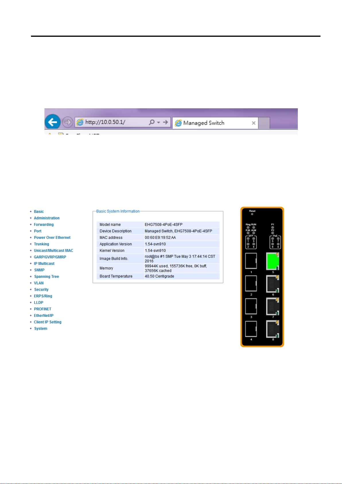
2. Type in the switch IP address (e.g. http://10.0.50.1), as shown in Figure 2.1).
Note: When the user name and password is left empty, the login prompt will not show.
Figure 2.1 IP Address for Web-based Setting
After the login process, the main interface will show up, as shown in Figure 2.2. The main menu (left side of the
screen) provides the links at the top level links of the menu hierarchy and by clicking each item allows lower level
links to be displayed. Note that in this case the Port 5 is highlighted in green, indicating that the port is being
connected. Detailed explanations of each subsection will be addressed later as necessary.
Page 16 of 190
Figure 2.2 Default Web Interface
Page 17
Industrial Managed
Ethernet Switch
User Manual
Configuring with a
Web Browser
2.2 Basic Information
To help users become familiar with the device, the Basic section provides important details of the switch. This is
also the main welcome screen once the user has logged in. The details make it easier to identify different
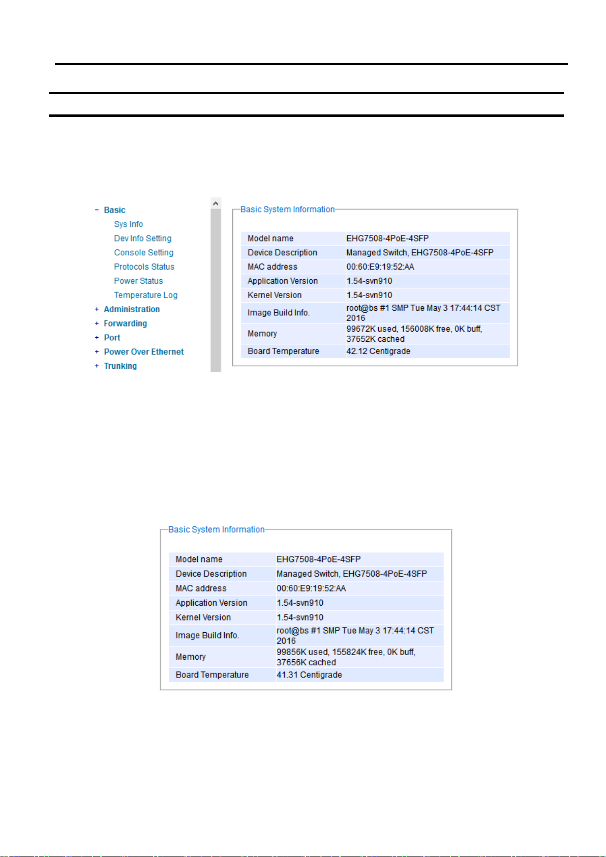
switches connected to the network. The Basic section is categorized into six subsections as shown in the left
panel of Figure 2.3.
Figure 2.3 Basic Information Dropdown Menu
2.2.1 Sys Info
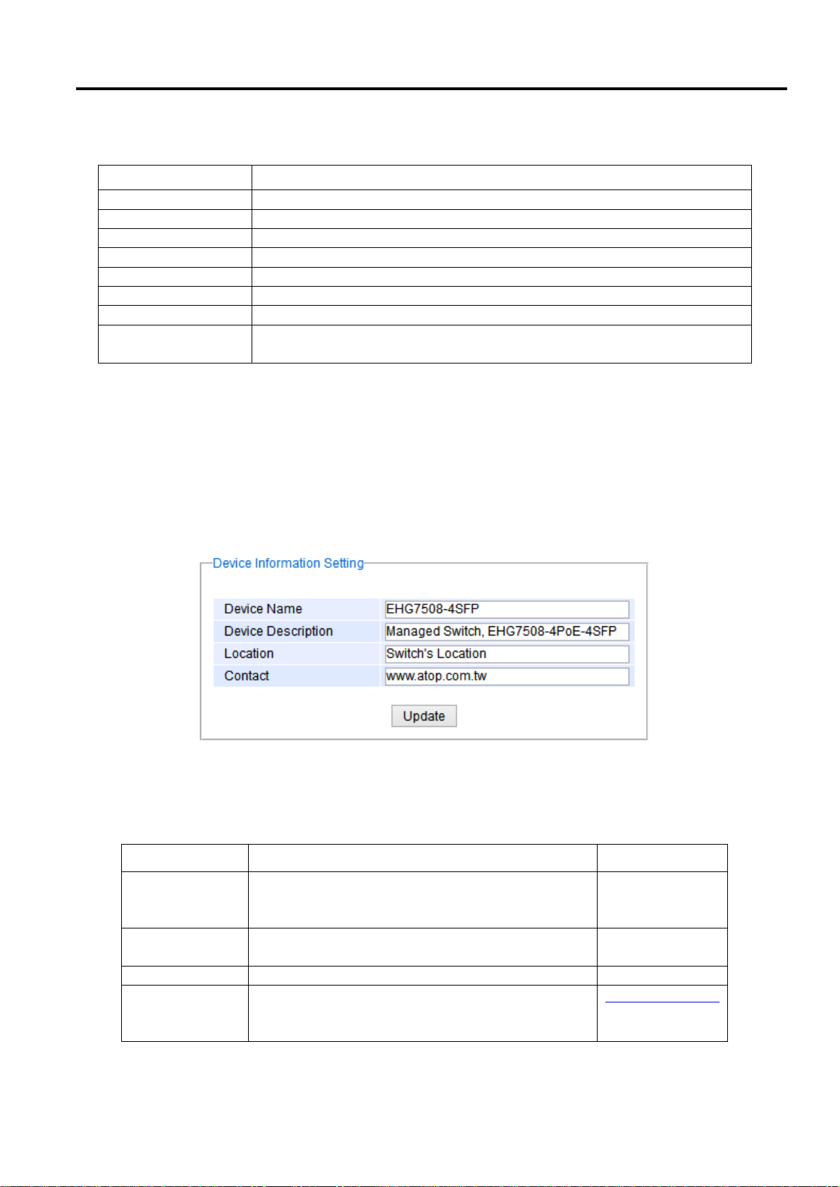
This subsection provides basic system information of Atop’s industrial managed switch. The user can check the
model name, device description, MAC address, firmware version, image build information, memory usage of the
switch, and current board’s temperature. Note that Atop’s firmware generally consists of application version and
kernel version. Figure 2.4 depicts an example of Basic System Information of EHG7508-4PoE-4SFP. Table 2.1
summarizes the description of each basic information.
Page 17 of 190
Figure 2.4 Details of Sys Info Webpage
Page 18
Industrial Managed
Ethernet Switch
User Manual
Configuring with a
Web Browser
Label
Description
Model name
The device’s complete model name
Device Description
The model type of the device
MAC address
The MAC address of the device
Application Version
The current application version of the device.
Kernel Version
The current kernel version of the device.
Image Build Info.
Information about the firmware image such as date of creation
Memory
The current RAM’s availability and the size of cached and shared memory.
Board Temperature
The current temperature of the board inside the chassis in degree Celsius
(a.k.a. Centigrade)
Label
Description
Factory Default
Device Name
Specifies a particular role or application of different
switches. The name entered here will also be shown
in Atop’s Device Management Utility. Max. 63 Char.
(Model name)
Device
Description
Detailed description of the unit. Max. 63 Characters.
Managed Switch
+ (Model name)
Location
Location of the switch.Max. 63 Characters.
Switch Location
Contact
Provides contact information for maintenance. Enter
the name of whom to contact in case a problem
occurs. Max. 63 Characters.
www.atop.com.tw
Table 2.1 Descriptions of the Basic information
2.2.2 Device Information Setting
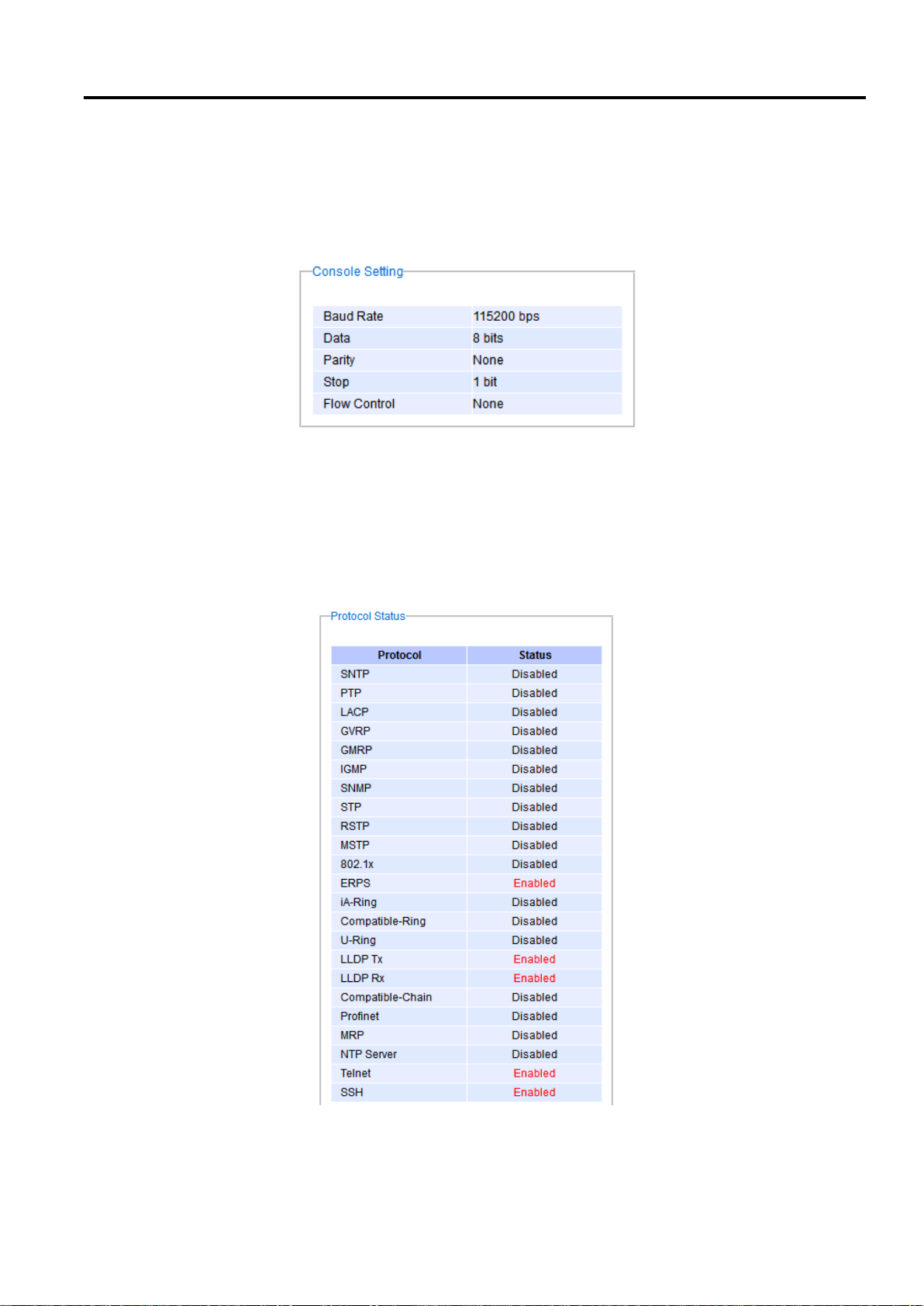
Users can assign device’s details to Atop’s switch in this subsection. By entering unique and relevant system
information such as device name, device description, location, and contact, this information can help identify one
specific switch among all other devices in the network that supports SNMP. Please click on the “Update” button to
update the information on the switch. Figure 2.5 shows Device Information Setting page of an EHG7508 managed
switch model. Table 2.2 summarizes the device information setting descriptions and corresponding default factory
settings.
Figure 2.5 Details of Device Information Settings Webpage
Table 2.2 Descriptions of the System Settings
Page 18 of 190
Page 19
Industrial Managed
Ethernet Switch
User Manual
Configuring with a
Web Browser
2.2.3 Console Setting
In this chapter, we use a web browser for configuring the switch. For the serial console method, please go to
Chapter 3 Configuring with Serial Console for more detail on how to connect console to the switch. The Console
Setting here only shows the setting parameters of a serial console’s connection, which can be used by a console
software such as Tera Term. Figure 2.6 below shows an example of the serial console’s connection parameters.
Figure 2.6 Setting Parameters for the Console Method
2.2.4 Protocols Status
Protocols Status subsection reports status of all protocols in the switch. While users can view status of all
protocols at once in this webpage, the detailed explanation of each protocol and method will be provided in the
following sections. Figure 2.7 shows the web interface for the Protocol Status page.
Page 19 of 190
Figure 2.7 Protocol Status Webpage
Page 20
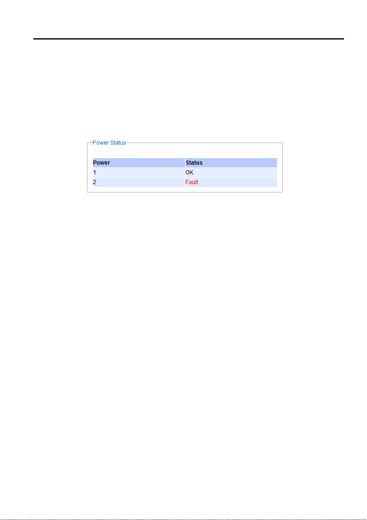
Industrial Managed
Ethernet Switch
User Manual
Configuring with a
Web Browser
2.2.5 Power Status
Atop’s managed switch features dual VDC power supply inputs. For Non-PoE models, 9-57VDC can be supplied to
Power Input 1 (V1+ and V1- pins) and/or Power Input 2 (V2+ and V2- pins). For PoE models, 45-57VDC should be
supplied under 802.3af mode and 51-57VDC should be supplied under 802.3at mode. For instance, the EHG75084PoE-4SFP has the following three power ratings: 9-57VDC with a maximum current of 2.8 Amperes (No PoE
mode), 45-57VDC with a maximum current of 1.7 Amperes (802.3af mode), and 51-57VDC with a maximum current
of 2.3 Amperes (802.3at mode). Figure 2.8 shows the status of each power input. A “Fault” status means that the
power on that supply input is either not connected or the power is not supplied properly.
Figure 2.8 Power Status Webpage
2.2.6 Temperature Log
This subsection provides user and system temperature logs. There are summary statistics and distribution of
temperature information for each log. The highest temperature, the lowest temperature and the average
temperature are reported in degree Celsius. Additionally, there is a recorded time which shows the time since the
temperature log were recorded. Under the summary statistics, there is a table showing the ranges of temperature,
percentages of time in each range, and amount of time in each range. The user can reset the user statistics by
clicking on the Reset button at the bottom of User Temperature Log. However, the system temperature log cannot
be reset by the users. Note that the information is not automatically update. Information provided in this webpage
will help the users to monitor the status of the industrial managed switch in harsh environment. The users have to
click reload on the web browser to update for the latest statistics. Figure 2.9 shows the User Temperature Log box
and Figure 2.10 shows the System Temperature Log box.
Note that there is a sensor component in the industrial managed switch which can detect the inside temperature.
The software inside the switch can read the sensor’s data and transform it into temperature in a unit of degree
Celsius. Because the device is airtight, the inside temperature will be higher than the outside temperature around
20 degrees. For the industry level switches, the lowest operating temperature (outside) will be around -20 to -40
degrees Celsius and the highest operating temperature (outside) will be around 70 to 85 degrees Celsius.
Page 20 of 190
Page 21
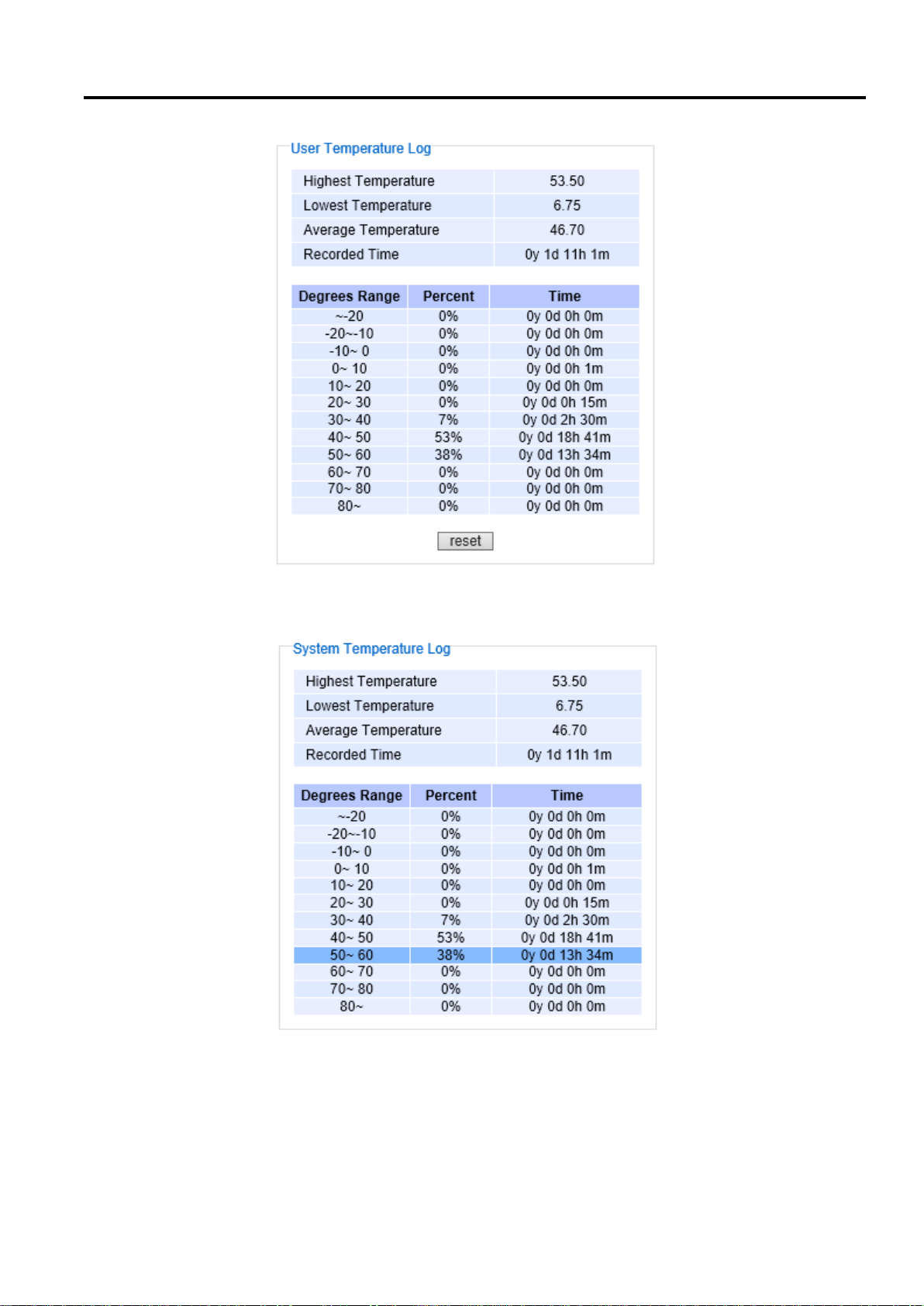
Industrial Managed
Ethernet Switch
User Manual
Configuring with a
Web Browser
Figure 2.9 User Temperature Log
Page 21 of 190
Figure 2.10 System Temperature Log
Page 22
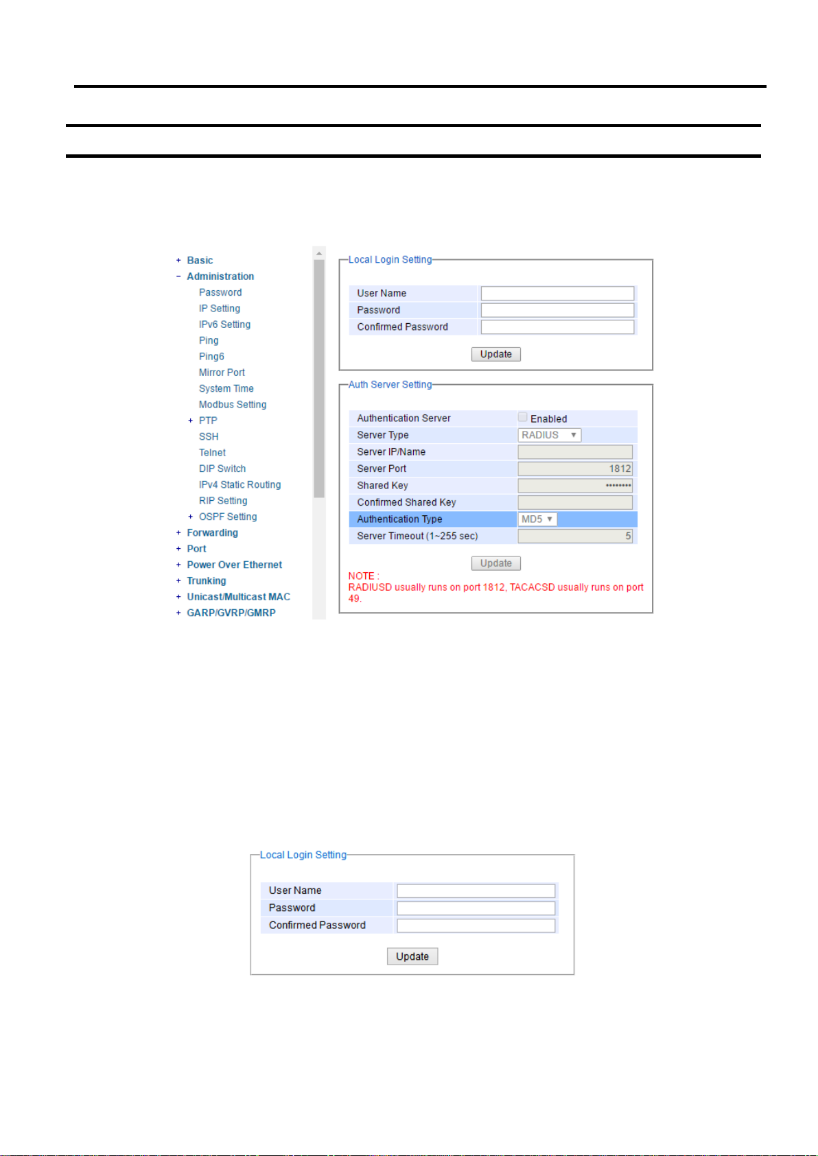
Industrial Managed
Ethernet Switch
User Manual
Configuring with a
Web Browser
2.3 Administration
In this section, users will be able to configure Password, IP Settings, IPv6 Setting, Ping, Ping6, Mirror Port,
System Time, Modbus Setting, PTP, SSH, Telnet, and DIP Switch. Figure 2.11 shows the Administration section
with the list of its subsections on the left of the screen.
Figure 2.11 Administration Dropdown Menu
2.3.1 Password
Password “default” is set for the device when it is manufactured. Users can modify it password to ensure overall
system security. The user name and password can be updated in this page as shown in Figure 2.12. Setting for a
local authentication is introduced in this subsection, while setting for a remote authentication is described in later
sections. The user name and password set here are applied to all types of access to Atop’s switch: web
management user interface (UI), secure shell (SSH), and command line interface (CLI). Please click on the “Update”
button to update the user name and password information on the switch. Table 2.3 summarizes the description of
each field.
Figure 2.12 Password Setting Webpage
Page 22 of 190
Page 23
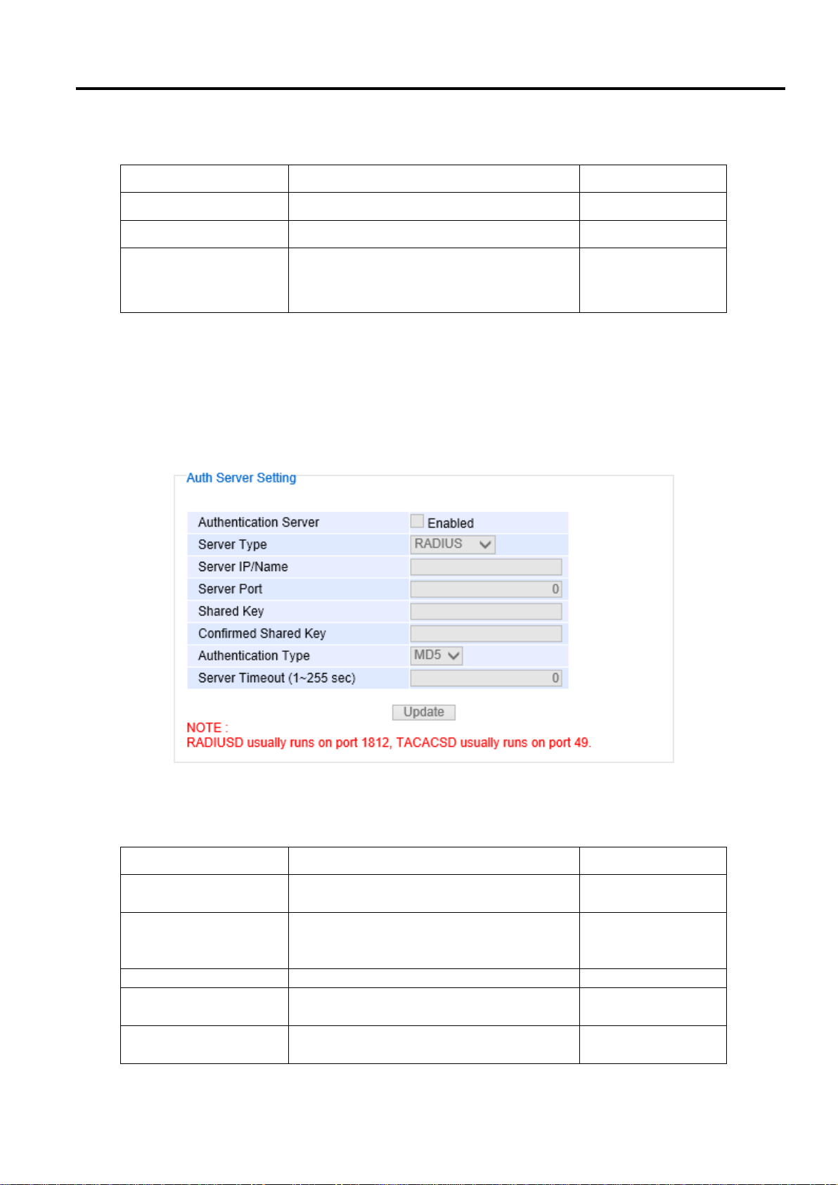
Industrial Managed
Ethernet Switch
User Manual
Configuring with a
Web Browser
Label
Description
Factory Default
User name
User’s Name. Max. 15 characters.
NULL
Password
Password to log-in. Max. 15 characters.
NULL
Confirmed Password
Re-type the password. This has to be
exactly the same as the password entered
in the above field. Max.15 characters.
NULL
Label
Description
Factory Default
Authentication Server
Enable / disable authentication through a
remote authentication server
Disabled
Server Type
Choose Authentication Server type: RADIUS
or TACACS+. See notes below for a detailed
explanation.
RADIUS
Server IP/Name
IP address of the authentication server
NULL
Server Port
Communication port of the authentication
server
1812
Shared Key
The key used to authenticate with the
server. Max 15 characters.
12345678
Table 2.3 Descriptions of Password Setting
In addition to the local authentication, the switch can be configured to request for authentication through a
centralized RADIUS or TACACS+ server when the local authentication fails. Figure 2.13 shows the setting
parameters for authentication server while Table 2.4 summarizes the authentication server settings. For the
RADIUS and TACACS+ comparison, please refer to Table 2.5 so that you can choose the solution that best suits
your needs.
Table 2.4 Authentication Server Settings
Page 23 of 190
Figure 2.13 Authentication Server Setting
Page 24

Industrial Managed
Ethernet Switch
User Manual
Configuring with a
Web Browser
Confirmed Shared Key
Re-type the shared key. Max 15 characters.
NULL
Authentication Type
Authentication mechanism. For RADIUS:
MD5. For TACACS+: ASCII, PAP, CHAP,
MSCHAP.
RADIUS is MD5
TACACS+ is ASCII
Server Timeout (1~255
sec)
The time out period of waiting for a
response from the authentication server.
This will affect the time that the next login
prompt shows up in case that the server is
not available.
5
RADIUS
TACACS+
Transport Protocol
UDP
TCP
Authentication and
Authorization
Separates AAA
Combines authentication and
authorization
Multiprotocol
Support
No
Yes, support AppleTalk Remote
Access (ARA) and NetBIOS
protocol
Confidentiality
Only password is encrypted
Entire packet is encrypted
*NOTE:
RADIUS (Remote Authentication Dial in User Service):
RADIUS is an access server that uses authentication, authorization, and accounting (AAA) protocol for
authentication and authorization. It is a distributed security system that secures remote access to networks and
network services against unauthorized access. The RADIUS specification is described in RFC 2865, which
obsoletes RFC 2138.
TACACS+ (Terminal Access Controller Access-Control System Plus):
TACACS+ is a security application that provides centralized validation of users attempting to gain access to a router
or network access server. The TACACS+ specification is described in Cisco's TACACS+ RFC draft.
Table 2.5 Comparison of Authentication Server Settings between RADIUS and TACACS+
2.3.2 IP Setting
In this subsection, users may modify network settings of Internet Protocol version 4 (IPv4) for the managed switch.
Additionally, on industrial managed switch, any virtual local area network (VLAN) group can be assigned an IP
interface address. There are two types of IP setting that can be done in this subsection: 1) setting managed (or
management) interface IP address and 2) setting IP interface address for VLAN. Note that a VLAN group must be
created first as described in Section 2.13.2.1 before assigning an IP interface address in this section. Each IP
interface address is a separated subnet. The user can configure multiple IP interface addresses on the switch. The
IP interface of VLAN 1 is the default managed (or management) interface of the switch as configured in Section
2.13.1.
This subsection is divided into two parts: IP Setting and IP Interface. The IP Setting part is depicted in Figure 2.14.
The Managed Interface VID has a default value of 1. Note that the DHCP option, Static IP Address, and Subnet
Mask cannot be changed in this part for the default managed interface VID = 1. However, the Gateway, the Primary
Page 24 of 190
Page 25
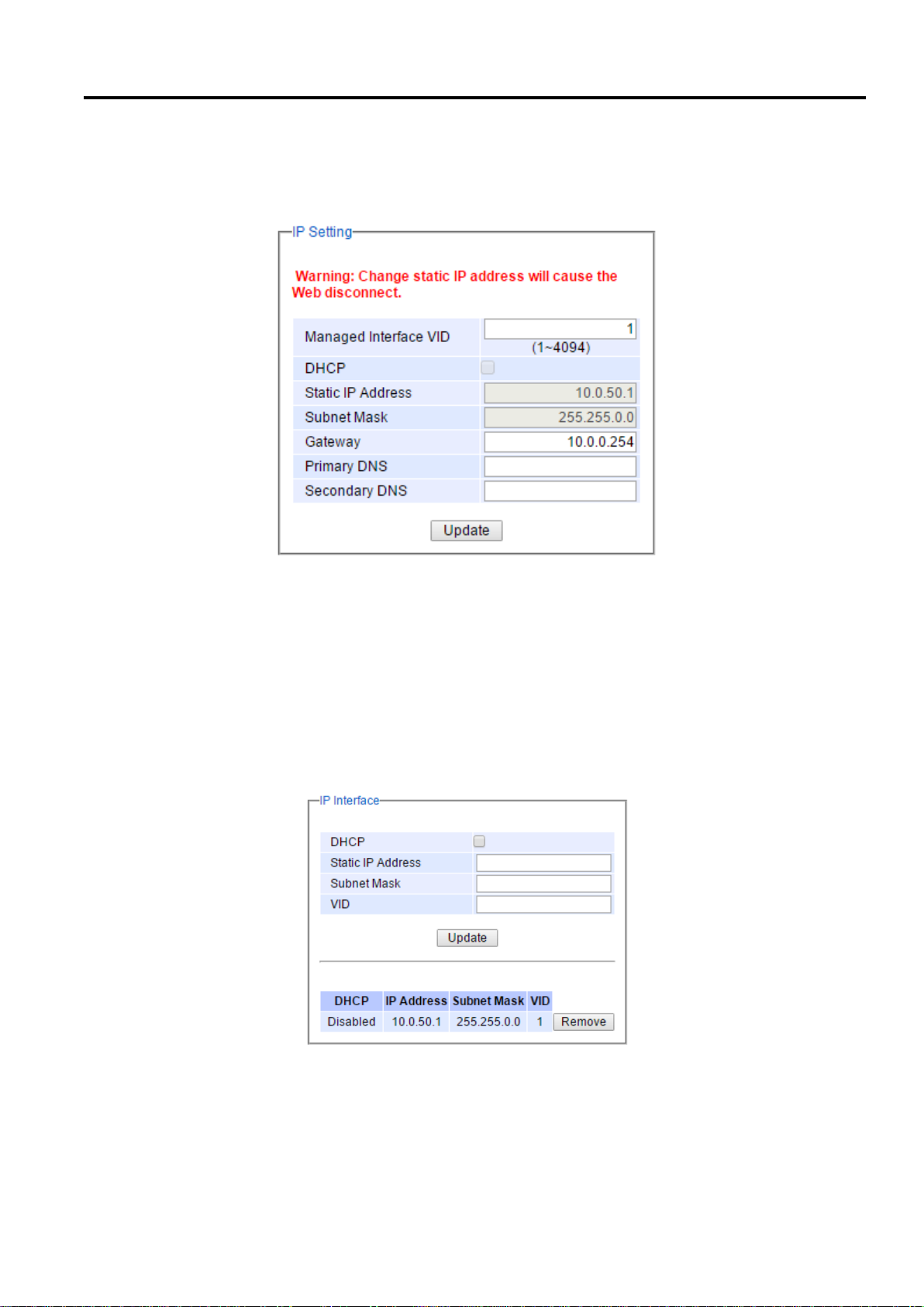
Industrial Managed
Ethernet Switch
User Manual
Configuring with a
Web Browser
DNS and Secondary DNS can be entered. The user can configure the default Gateway and DNS for all IP interfaces
in this part of the webpage. If the user set gateway or DNS on this page, the managed switch will not set the gateway
or the DNS from DHCP server. After entering the desired information, please click Update button to change the IP
Setting.
Figure 2.14 IP Setting under IP Setting Webpage
The second part of IP Setting section is the IP Interface part as shown in Figure 2.15. In this part, there is a table at
the bottom that lists the IP interface information of each VLAN Identification number (VID). The user can configure
IP interface address for VLAN 1 to 4094 in this IP interface part. Note that the maximum number of IP interface is
32. The user can remove each entry in the table by clicking on the Remove button. The user can configure the IP
Interface address for each VLAN ID (VID) in this part. To change the IPv4 address of the managed switch (default
is 10.0.50.1), the user can enter a new Static IP Address and new Subnet Mask and VID = 1 then clicking Update
button. Note that the user will need to manually update the new IP address in the URL field of the web browser if
the IP address of the managed switch is changed.
Figure 2.15 IP Interface Part under IP Setting Webpage
To configure IP interface address for other VLAN Identification number (VID), enter the desired Static IP Address,
Subnet Mask, and the VID, and then click on the Update button. Additionally, each IP interface of the switch can
enable the Dynamic Host Configuration Protocol (DHCP) by checking the DHCP box option to obtain an IP address
Page 25 of 190
Page 26

Industrial Managed
Ethernet Switch
User Manual
Configuring with a
Web Browser
Label
Description
Factory
Default
Managed Interface
VID
Virtual local area network identification number of the
managed (or management) interface of the managed
switch
1
DHCP
By checking this box, an IP address and related fields will
be automatically assigned. Otherwise, users can set up
the static IP address and related fields manually.
Uncheck
Static IP Address
Display current IP address. Users can also set a new static
IP address for the device.
10.0.50.1
Subnet Mask
Display current Subnet Mask or set a new subnet mask.
255.255.0.0
Gateway
Show current Gateway or set a new one.
0.0.0.0
Primary DNS
Set the primary DNS IP address to be used by your
network.
NULL
Secondary DNS
Set the secondary DNS IP address. The Ethernet switch
will locate the secondary DNS server if it fails to connect
to the Primary DNS Server.
NULL
VID
Virtual local area network identification number is the ID
value for VLAN that need to be configured with IPv4
address.
NULL
and related information automatically from a DHCP server thus reducing the work for an administrator. Note that
when checking the DHCP option, the Static IP Address and the Subnet Mask will be inactive. The only field that can
be entered is the VID which means that the VID will obtain the IPv4 address automatically for its interface. Note
that before deleting any VLAN group as described in Section 2.13.2.1, please make sure that the VID does not
establish an IP interface. The description of each field and its default value in IP Setting webpage are summarized
in Table 2.6.
Table 2.6 Descriptions of IP Settings
Page 26 of 190
Page 27
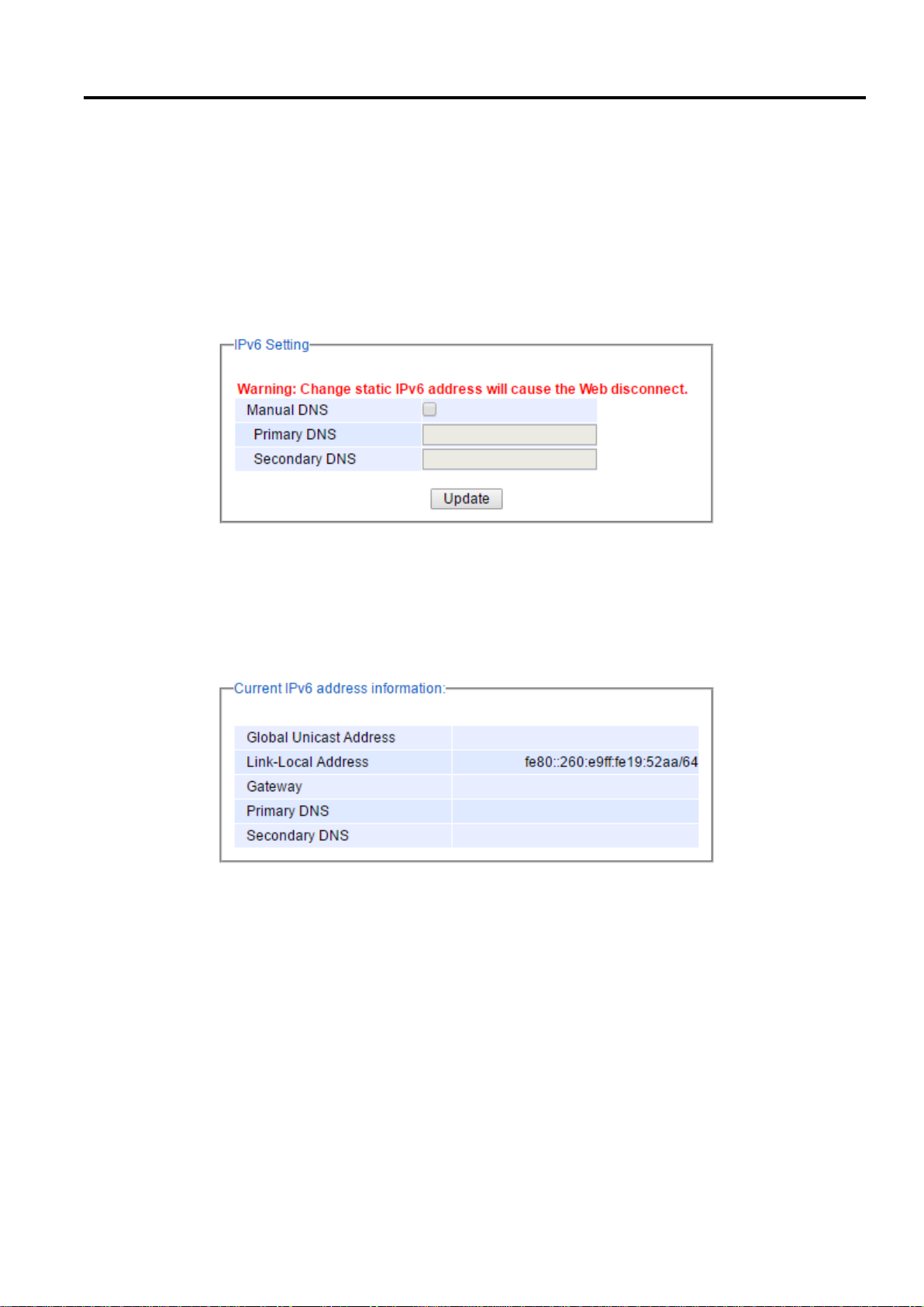
Industrial Managed
Ethernet Switch
User Manual
Configuring with a
Web Browser
2.3.3 IPv6 Setting
This subsection enables Atop’s industrial managed switch to operate in Internet Protocol version 6 (IPv6) network.
The webpage is subdivided into three parts: IPv6 Setting, Current IPv6 address information, and IP interface for
IPv6. The first part called IPv6 Setting is shown in Figure 2.16 and allows the users to configure the Domain Name
Service (DNS) for IPv6 network. The users have a choice to enable or disable the Manual DNS by checking the box
behind it. When the Manual DNS option is checked, the users will be able to enter the IPv6 addresses of the Primary
DNS and the Secondary DNS. If the users change any DNS setting, please clicking on the Update button to allow
the new configuration to take effect.
Figure 2.16 IPv6 Setting Part of IPv6 Setting Webpage
The second part called Current IPv6 address information is shown in Figure 2.17. This part of the web page
summarizes the current IPv6 address information of the managed switch, which are the Global Unicast Address,
Link-Local Address, Gateway, Primary DNS, and Secondary DNS.
Figure 2.17 Current IPv6 Address Information Part of IPv6 Setting Page
The third part called IP Interface for IPv6 is shown in Figure 2.18. Similar to IPv4 Setting in previous subsection,
the IPv6 Setting also allows the user to set IPv6 interface address for a virtual local area network (VLAN) group
based on the VLAN identification number (VID). For managed switch, the users have options to enable Autoconfig,
DHCPv6, or Manual setting. Note that in IPv6 network, there are three types of auto configuration: stateless, stateful,
and a combination of both. The “Autoconfig” option here is the stateless configuration, while the “DHCPv6” option
is the stateful configuration. If the users check both the Autoconfig and the DHCPv6 options, the switch will use
the combination of stateless and stateful configuration. When selecting the “Manual” option, he users will have to
Page 27 of 190
Page 28
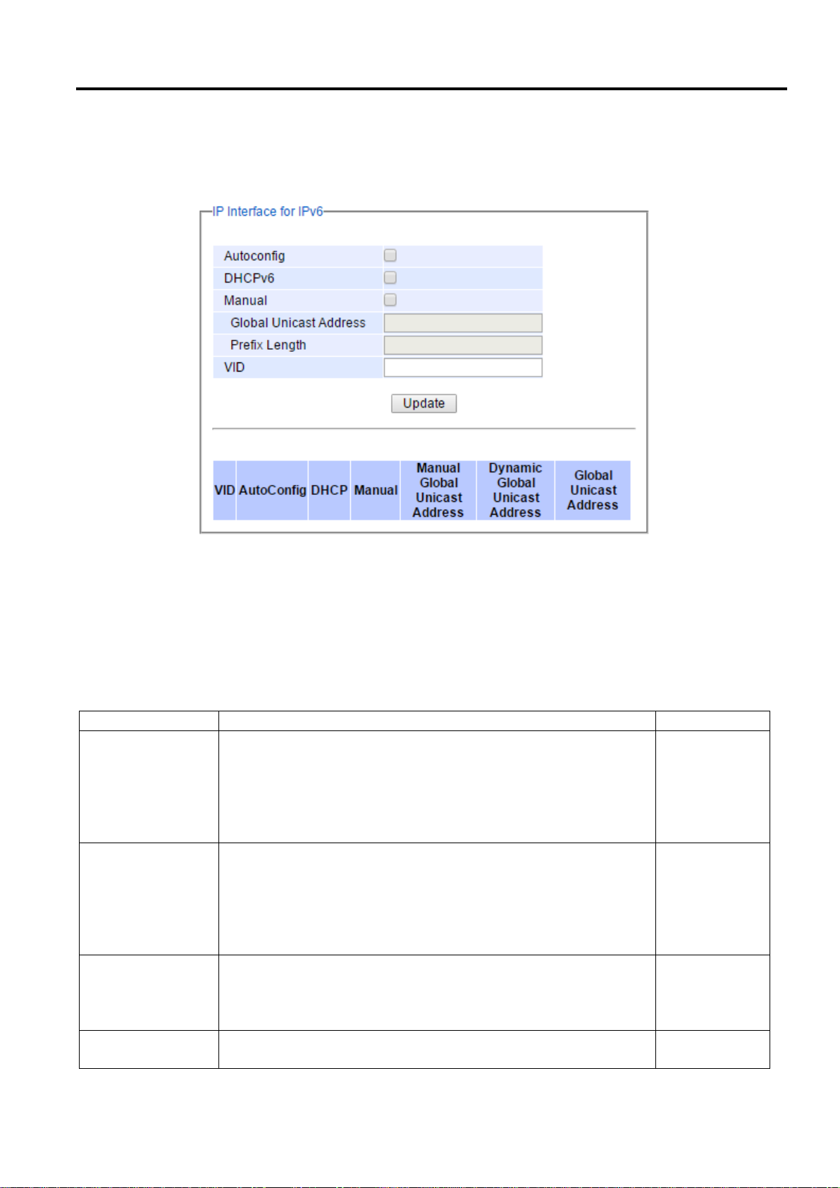
Industrial Managed
Ethernet Switch
User Manual
Configuring with a
Web Browser
Label
Description
Factory Default
Autoconfig
By checking this box, all IPv6 setting will be automatically configured
for the users. This option is based on the stateless autoconfiguration
in which the switch uses information in router advertisement
messages to configure an IPv6 address. The address will be a
concatenation of first 64 bits from the router advertisement source
address with the Extended Unique Identifier (EUI-64).
Uncheck
DHCPv6
By checking this box, an IPv6 address and related fields will be
automatically assigned from a DHCPv6 server in the network. This
is a stateful auto configuration in which the switch will generate a
DHCP solicit message to the ALL-DHCP-Agents multicast address
to find DHCPv6 server. Otherwise, users can set up the IPv6 address
manually.
Uncheck
Manual
By checking this box, users must provide Global Unicast Address,
Prefix Length, and Gateway address in the following fields. Note that
when this option is checked, the next three fields will become active
for setting.
Uncheck
Global Unicast
Address
Set an IPv6 address that is routable across the Internet and its three
high-level bits are 001. The IPv6 address is in the format 2XXX::/3.
NULL
enter the Global Unicast Address, Prefix Length, and Gateway. After finishing the setting, please click on the Update
button to allow the new configuration to take effect.
Figure 2.18 IP Interface for IPv6 Part of IPv6 Setting Webpage
At the bottom of this part as shown in Figure 2.18, there is also a list of IPv6 interface setting for each VLAN
identification number (VID). The users can click on the Remove button at the end of the line to remove any entry
(or remove IPv6 interface address setting) from this list which is similar to the IPv4 Setting in previous subsection.
Table 2.7 explains each field in the IPv6 Setting webpage.
Table 2.7 Description of IPv6 Setting
Page 28 of 190
Page 29
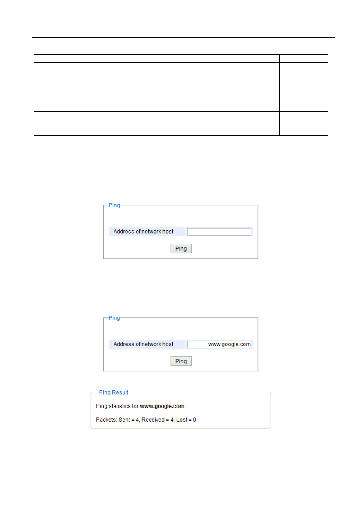
Industrial Managed
Ethernet Switch
User Manual
Configuring with a
Web Browser
Label
Description
Factory Default
Prefix Length
Set a prefix length for the IPv6 address in previous field.
NULL
Gateway
Set the IPv6 address of an IPv6 Gateway
NULL
Manual DNS
By checking this box, user must manually provide Primary and
Secondary DNS addresses for IPv6. Note that when this option is
checked, the next two fields will become active for setting.
Uncheck
Primary DNS
Set the primary DNS IPv6 address to be used by your network.
NULL
Secondary DNS
Set the secondary DNS IPv6 address. The Ethernet switch will locate
the secondary DNS server if it fails to connect to the Primary DNS
Server.
NULL
2.3.4 Ping
Atop’s managed switch provides a network tool called Ping for testing network connectivity in this subsection. Ping
is a network diagnostic utility for testing reachability between a destination device and the managed switch. Note
that this utility is only for IPv4 address. The Ping utility for IPv6 will be provided in the next subsection. Figure 2.19
shows the user interface for using the Ping command.
Figure 2.19 Ping Webpage
Users can enter an IP address or a domain name into the field to verify network connectivity as shown in Figure
2.20. After entering the IP address/name, please click “Ping” button to run the ping function. Example of successful
ping result is shown in Figure 2.21 while a failure ping result is depicted in Figure 2.22.
Figure 2.20 Example of Ping Command
Figure 2.21 Example of successful ping command result
Page 29 of 190
Page 30
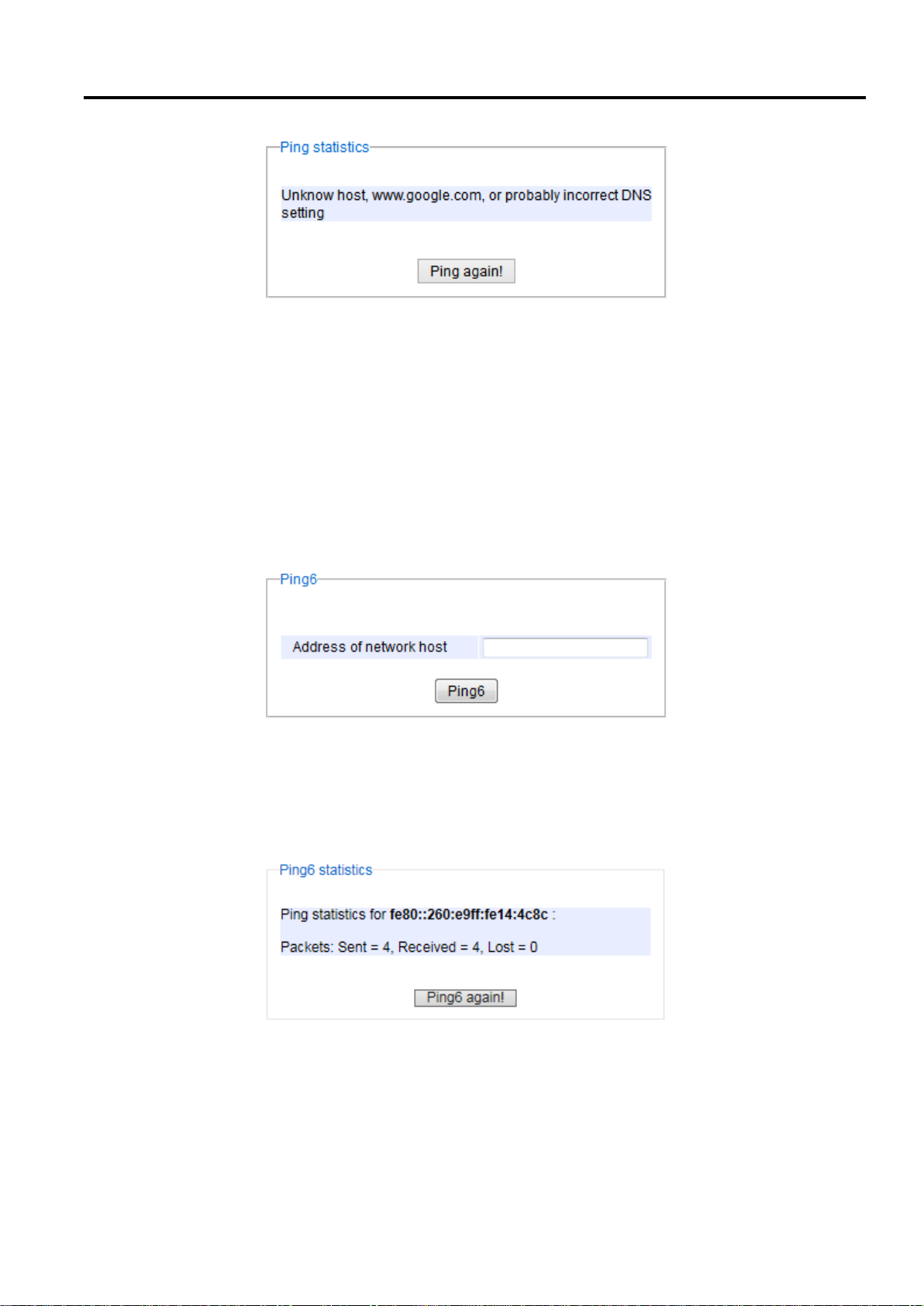
Industrial Managed
Ethernet Switch
User Manual
Configuring with a
Web Browser
Figure 2.22 Example of unsuccessful ping command result
*Note:
If users enter a domain name instead of an IP address, they should assign a DNS first. This can be done through
Administration > IP Setting as shown in Section 2.3.2.
2.3.5 Ping6
Ping6 is a corresponding network diagnostic utility for testing reachability between a destination device and the
managed switch in IPv6 network. Figure 2.23 shows the user interface for using the Ping command.
Figure 2.23 Ping6 Webpage
Users can enter an IPv6 address into the field to verify network connectivity. After entering the IPv6 address, please
click “Ping6” button to start the ping function. Examples of successful ping6 results are shown in Figure 2.24.
Figure 2.24 Example of Successful Ping6 Result
Page 30 of 190
Page 31
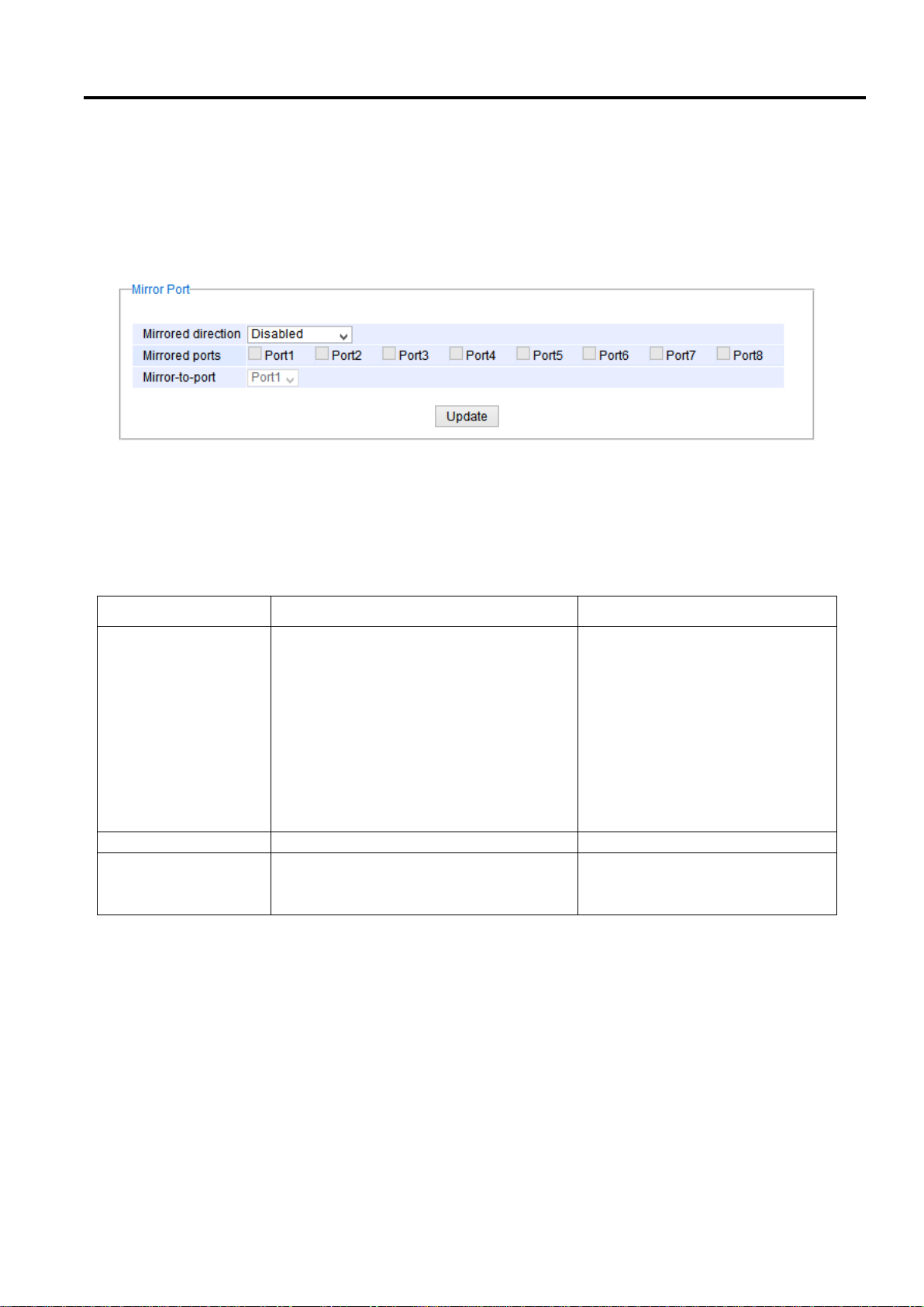
Industrial Managed
Ethernet Switch
User Manual
Configuring with a
Web Browser
Label
Description
Factory Default
Monitored direction
Select the monitoring direction.
- Disable: To disable port monitoring.
- Input data stream: To monitor input data
stream of monitored ports only
- Output data stream: To monitor output
data stream of monitored ports only
- Input/Output data stream: To monitor
both input and output data stream of
monitored ports
Disabled
Monitored Port
Select the ports that will be monitored
Unchecked all
Mirror-to-port
Select the mirror port that will be used to
monitor the activity of the monitored
ports
Port1
2.3.6 Mirror Port
In order to help the network administrator keeps track of network activities, the managed switch supports port
mirroring, which allows incoming and/or outgoing traffic to be monitored by a single port that is defined as a mirror
port. Note that the mirrored network traffic can be analyzed by a network analyzer or a sniffer for network
performance or security monitoring purposes. Figure 2.25 shows the Mirror Port webpage. The descriptions of port
mirroring options are summarized in Table 2.8.
Figure 2.25 Mirror Port Webpage
*Note:
Overflow will occur if the total throughput of the monitoring ports exceeds what the mirror port can support.
Table 2.8 Description of Port Mirroring Options
Page 31 of 190
Page 32
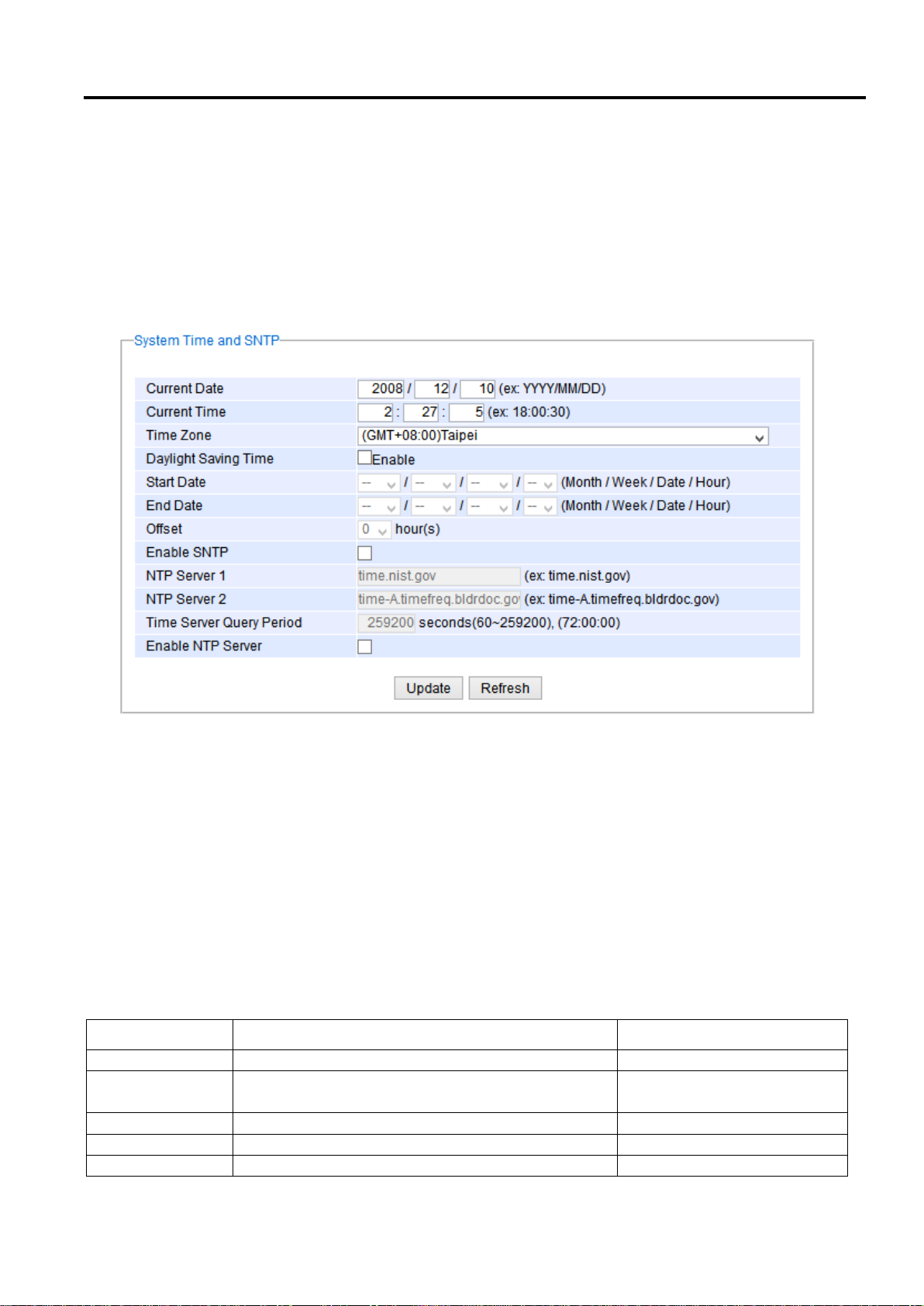
Industrial Managed
Ethernet Switch
User Manual
Configuring with a
Web Browser
Label
Description
Factory Default
Current Date
Allows local date configuration in yyyy/mm/dd format
None
Current Time
Allows local time configuration in local 24-hour
format
None
Time Zone
The user’s current local time
(GMT+08:00) Taipei
Daylight Saving
Enable or disable Daylight Saving Time function
Unchecked
Start Date
Define the start date of daylight saving
NULL
2.3.7 System Time
Atop’s industrial managed switch has internal calendar (date) and clock (or system time) which can be set manually
or automatically. Figure 2.26 shows the System Time and SNTP webpage. The users have options to configure
Current Date and Current Time manually. There is a drop-down list of Time Zone which can be selected for the
local time zone. If the switch is deployed in a region where daylight saving time is practiced (see note below for
explanation), please check the Enable option for Daylight Saving Time. Then, the users will have to enter the Start
Date, End Date, and Offset in hour(s).
Figure 2.26 Webpage for Setting System Time and SNTP
For automatically date and time setting, the users can enable Simple Network Time Protocol (SNTP) by checking
the Enable SNTP option (see note below for explanation). Then, the users must enter the NTP Server 1 and NTP
Server 2 which will be used as the reference servers to synchronize date and time to. The users can specify the
Time Server Query Period for synchronization which is in the order of seconds. The value for this period will depend
on how much clock accuracy the users want the switch to be. Finally, the managed switch can become a network
time protocol server for the local devices by checking the box behind the Enable NTP Server option. Description of
each option is provided in Table 2.9.
Table 2.9 Descriptions of the System Time and the SNTP
Page 32 of 190
Page 33

Industrial Managed
Ethernet Switch
User Manual
Configuring with a
Web Browser
End Date
Define the end date of daylight saving
NULL
Offset
Decide how many hours to be shifted
forward/backward when daylight saving time begins
and ends. See note below.
0
Enable SNTP
Enables SNTP function. See note below.
Unchecked
NTP Server 1
Sets the first IP or Domain address of NTP Server.
time.nist.gov
NTP Server 2
Sets the second IP or Domain address of NTP Server.
Switch will locate the 2nd NTP Server if the 1st NTP
Server fails to connect.
time-A.timefreq.bldrdoc.gov
Time Server
Query Period
This parameter determines how frequently the time is
updated from the NTP server. If the end devices
require less accuracy, longer query time is more
suitable since it will cause less load to the switch.
The setting value can be in between 60 – 259200 (72
hours) seconds.
259,200 seconds.
Enable NTP
Server
This option will enable network time protocol (NTP)
daemon inside the managed switch which allows
other devices in the network to synchronize their
clock with this managed switch using NTP.
Unchecked
Note:
- Daylight Saving Time: In certain regions (e.g. US), local time is adjusted during the summer season in order to
provide an extra hour of daylight in the afternoon, and one hour is usually shifted forward or backward.
- SNTP: Simple Network Time Protocol is used to synchronize the computer systems’ clocks with a standard
NTP server. Examples of two NTP servers are time.nist.gov and time-A.timefreq
.bldrdoc.gov.
2.3.8 Modbus Setting
Atop’s managed switch can be connected to a Modbus network using Modbus TCP/IP protocol which is an
industrial network protocol for controlling automation equipment. The managed switch’s status and settings can
be read and written through Modbus TCP/IP protocol which operates similar to a Management Information Base
(MIB) browser. The managed switch will be a Modbus slave which can be remotely configured by a Modbus master.
The Modbus slave address must be set to match the setting inside the Modbus master. In order to access the
managed switch, a Modbus Address must be assigned as described in this subsection. A Modbus memory
mapping table, which lists all the register’s addresses inside the managed switch and their descriptions, is provide
in 7 Modbus Memory Map. Figure 2.27 shows the Modbus Setting webpage.
Figure 2.27 Webpage for Setting the Modbus Address
Page 33 of 190
Page 34
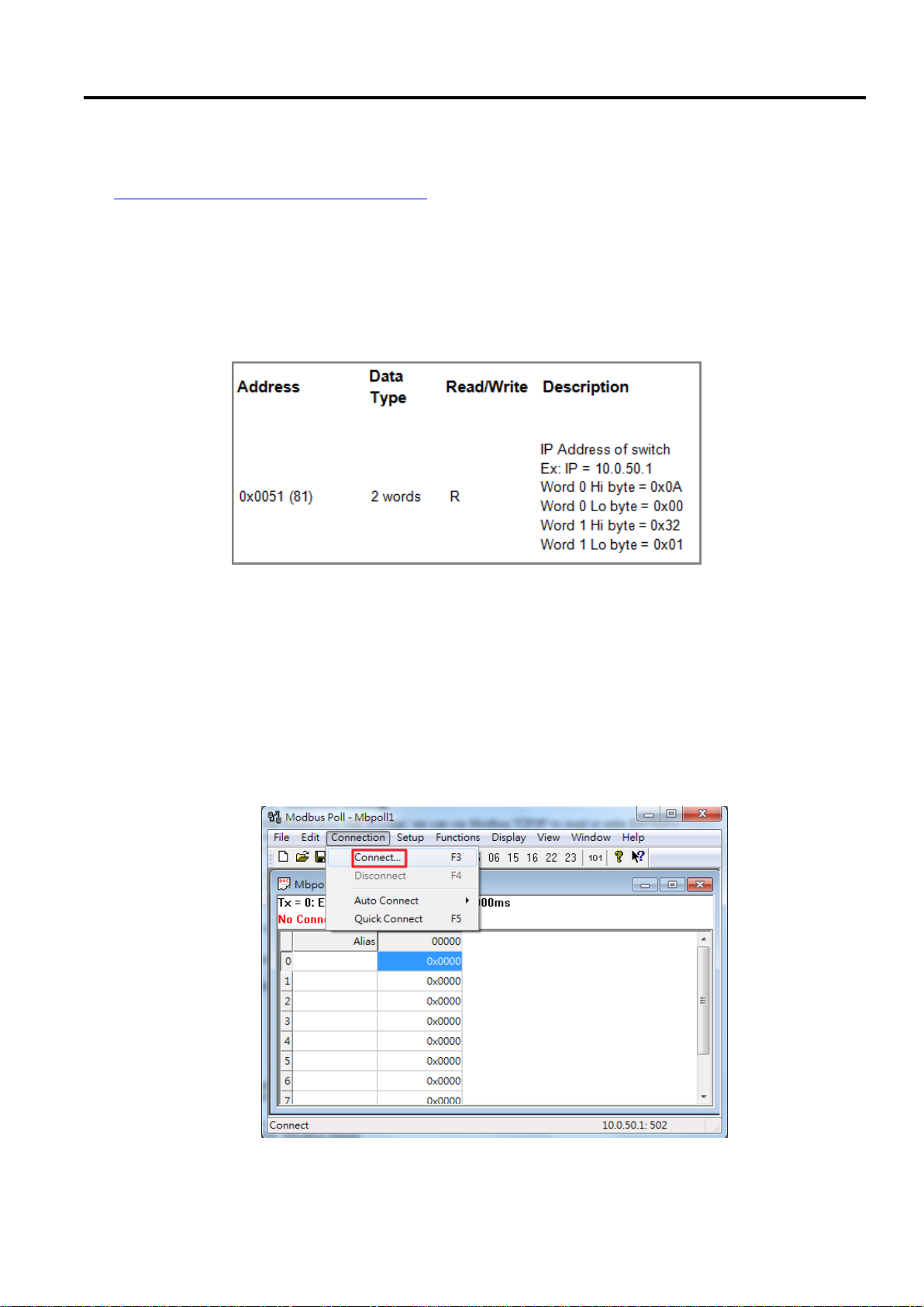
Industrial Managed
Ethernet Switch
User Manual
Configuring with a
Web Browser
Figure 2.27 shows the webpage that users can set up the Modbus ID address. Users can use Modbus TCP/IP
compatible applications such as Modbus Poll to configure the switch. Note that Modbus Poll can be download
from http://www.modbustools.com/download.html. The Modbus Poll 64-bit version 7.0.0, Build 1027 was used in
this document. Atop does not provide this software to the users. Tutorial of Modbus read and write examples are
illustrated below.
Note: The switch only supports Modbus function code 03, 04 (for Read) and 06 (for Write).
Read Registers (This example show how to read the switch’s IP address.)
Figure 2.28 Mapping Table of Modbus Address for Switch’s IP Address
1. Make sure that a supervising computer (Modbus Master) is connected to your target switch (Modbus
Slave) over Ethernet network.
2. Launch Modbus Poll in the supervising computer. Note a registration key may be required for a long term
use of Modbus Poll after 30-day evaluation period. Additionally, there is a 10-minute trial limitation for the
connection to the managed switch.
3. Click Connect button on the top toolbar to enter Connection Setup dialog by selecting Connect… menu as
shown in Figure 2.29.
Page 34 of 190
Figure 2.29 Entering Connection Setup Menu of the Modbus Poll
Page 35
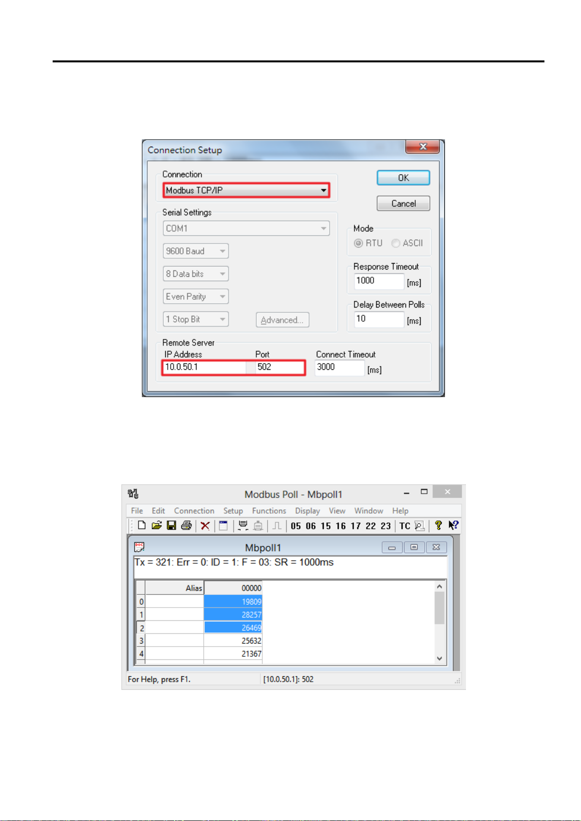
Industrial Managed
Ethernet Switch
User Manual
Configuring with a
Web Browser
4. Select Modbus TCP/IP as the Connection mode and enter the switch’s IP address inside the Remote
Modbus Server’s IP Address or Node Name field at the bottom as shown in Figure 2.30. The Port number
should be set to 502. Then click OK button.
Figure 2.30 Modbus Poll Connection Setup
5. On the window Mbpoll1, select multiple cells from row 0 to row 2 by clicking on cells in second column of
row 0 and row 2 while holding the shift key as shown in Figure 2.31.
Page 35 of 190
Figure 2.31 Multiple Cell Section in Modbus Poll
Page 36
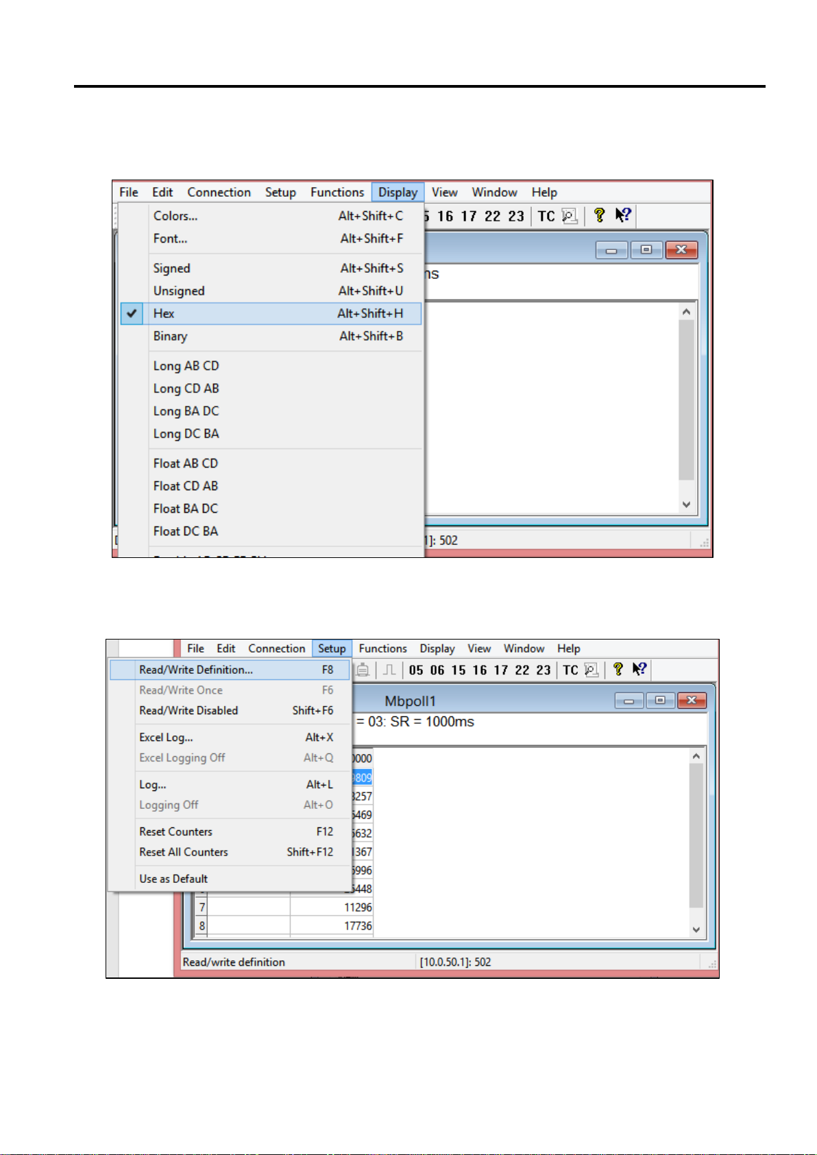
Industrial Managed
Ethernet Switch
User Manual
Configuring with a
Web Browser
6. Set Display mode of the selected cells in previous step to HEX (hexadecimal) by selecting Display pull-
down menu and choosing the Hex as shown in Figure 2.32.
Figure 2.32 Set Display Mode to Hex in Modbus Poll
7. Click on the Setup pull-down menu and choose Read/Write Definition… as shown in Figure 2.33.
Page 36 of 190
Figure 2.33 Modbus Poll Setup Read/Write Definition
Page 37
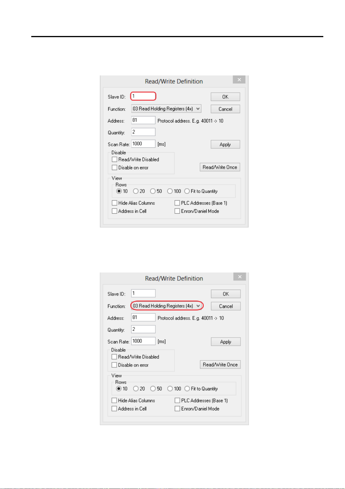
Industrial Managed
Ethernet Switch
User Manual
Configuring with a
Web Browser
8. Enter the Slave ID in the Modbus Poll function as shown in Figure 2.34, which should match the Modbus
Address = 1 entered in Figure 2.27 in Section 2.3.8 (Modbus Setting).
Figure 2.34 Slave ID in the Modbus Poll Function is set to 1
9. Select Function 03 or 04 because the managed switch supports function code 03 and 04 as shown in
Figure 2.35.
Page 37 of 190
Figure 2.35 Set Code 03 in the Modbus Poll Function
Page 38
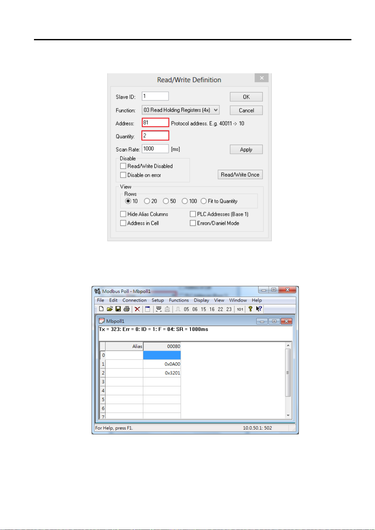
Industrial Managed
Ethernet Switch
User Manual
Configuring with a
Web Browser
10. Set starting Address to 81 and Quantity to 2 as shown in Figure 2.36.
Figure 2.36 Setup Starting Address and Quantity in Modbus Poll
11. Click OK button to read the IP address of the switch.
12. Modbus Poll will get the values 0x0A, 0x00, 0x32, 0x01, which means that the switch’s IP is 10.0.50.1 as
shown in Figure 2.37.
Page 38 of 190
Figure 2.37 Modbus Memory Address 81 and 82 are the location of EHG7508's IP Address
Page 39
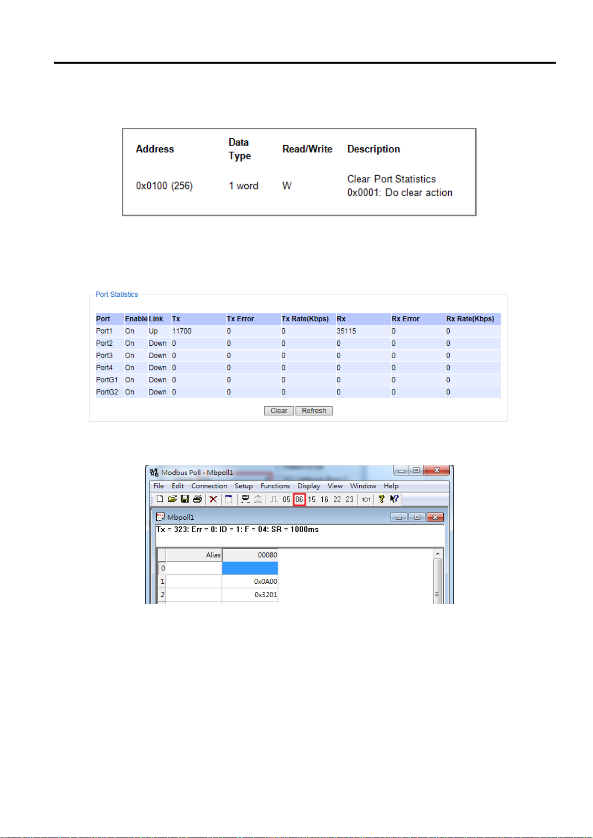
Industrial Managed
Ethernet Switch
User Manual
Configuring with a
Web Browser
Write Registers (This example shows how to clear the switch’s Port Count (Statistics).)
Figure 2.38 Mapping Table of Modbus Address for Clearing Port Statistics
1. Check the switch’s Port TX/RX counts in Port Statistics page (described in Section 2.5.4) as shown in
Figure 2.39.
Figure 2.39 Port Count in Port Statistics Webpage
2. Click function 06 on the toolbar as shown in Figure 2.40.
Figure 2.40 Click on Function 06 in the Modbus Poll
3. Set Address to 256 and Value (HEX) to 1 as shown in Figure 2.41, then click “Send” button.
Page 39 of 190
Page 40
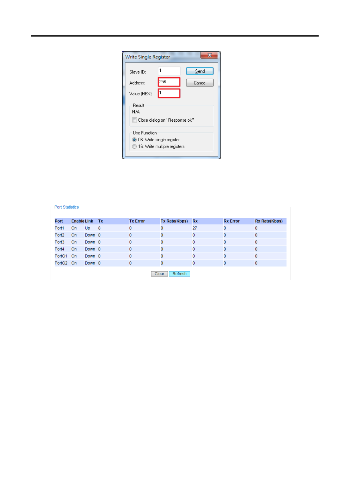
Industrial Managed
Ethernet Switch
User Manual
Configuring with a
Web Browser
Figure 2.41 Use Modbus Poll to Clear Switch's Port Count
4. Check Port Statistics (described in Section 2.5.4) in the managed switch’s Web UI as shown in Figure 2.42.
The packet count is now cleared.
Figure 2.42 Cleared Port Statistics
Page 40 of 190
Page 41

Industrial Managed
Ethernet Switch
User Manual
Configuring with a
Web Browser
2.3.9 Precision Time Protocol (PTP)
The Precision Time Protocol (PTP) is a high-precision time protocol. It can be used with measurement and control
systems in local area network that require precise time synchronization. This menu is divided into two submenus:
PTP Setting and H/W PTP as shown in Figure 2.43.
Figure 2.43 PTP's Submenu
Page 41 of 190
Page 42
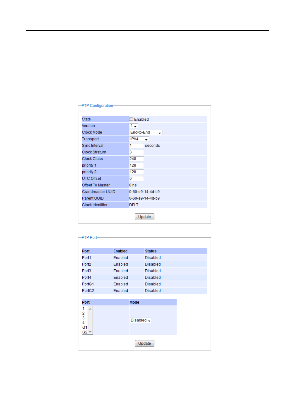
Industrial Managed
Ethernet Switch
User Manual
Configuring with a
Web Browser
2.3.9.1 PTP Setting
The PTP can be set in this PTP Setting webpage. Figure 2.44 shows the PTP Configuration webpage in which the
user can configure PTP and check its status. The lower part of Figure 2.44 allows the users to enable or disable the
PTP function per port and check their current status.
To enable PTP on the managed switch, please check the Enabled box behind the State option as shown in Figure
2.44. Note that the PTP will not be enabled per port if this State option is not checked. Please see description of
PTP configuration in Table 2.10 and description of PTP port information in Table 2.11. Note that after setting the
desired PTP options, please click Update button to allow the new configuration to take effect.
Page 42 of 190
Figure 2.44 PTP Setting Webpage, example taken from EH75XX series
Page 43

Industrial Managed
Ethernet Switch
User Manual
Configuring with a
Web Browser
Label
Description
Factory
Default
State
Enabled/Disable the PTP function. This is the main option that needs
to be enabled so that the port’s PTP function will work according to
other parameters defined in this table (Table 2.10).
Unchecked
Version
Set the PTP operation version. Note that v1 (IEEE 1588-2002) and v2
(IEEE 1588-2008) are supported.
1
Clock Mode
Select clock type of the PTP (Precision Time Protocol). The switch has
four modes: End-End Boundary Clock, End-End Transparent Clock
(TC), Peer-Peer Boundary Clock, and Peer-Peer Transparent Clock
(TC).
End-to-End
Transport
Select Ethernet (layer 2) multicast transport or layer 3 (UDP/IPv4)
multicast transports for PTP (Precision Time Protocol) messages.
IPV4
Sync Interval
Set the interval of the sync packet transmitted time. Small interval
causes too frequent sync, which will cause more load to the device
and network.
1
Clock Stratum
Set the Clock Stratum value. The lower values take precedence to be
selected as the master clock in the best master clock algorithm
(BMCA).
3
Clock Class
Clock Class represents clock’s accuracy level. It is an attribute of an
ordinary or boundary clock. It denotes time traceability or frequency
distributed by the grandmaster clock. Please refer to IEEE 1588-2008,
Table 5 for definitions, allowed values, and interpretation.
248
priority 1
Set the clock priority 1 (PTP version 2). The lower values take
precedence to be selected as the master clock in the best master
clock algorithm, 0 = highest priority, 255 = lowest priority.
128
priority 2
Set the clock priority 2 (PTP version 2). The lower values take
precedence to be selected as the master clock in the best master
clock algorithm (BMCA), 0 = highest priority, 255 = lowest priority.
128
UTC Offset
Coordinated Universal Time (UTC) offset value
0
Offset to Master
The offset time to the master clock
None
Grandmaster UUID
The Grandmaster UUID for PTP version 1
None
Parent UUID
The parent master UUID for PTP version 1
None
Clock Identifier
The clock identifier for PTP version 1
None
Label
Description
Factory Default
Port
Port number
-
Enabled
This is the port’s mode information which indicates whether the port’s
PTP function is enabled or disabled.
Enabled
Status
This is PTP’s per port operation status. If the per port function is
enabled, but the status is still disabled, please enable the PTP master
option (State option in Table 2.10).
Disabled
Mode
Enabled/Disabled PTP per port function
Disabled
Table 2.10 Description of PTP Setting
Table 2.11 Description of PTP Port Setting
Page 43 of 190
Page 44
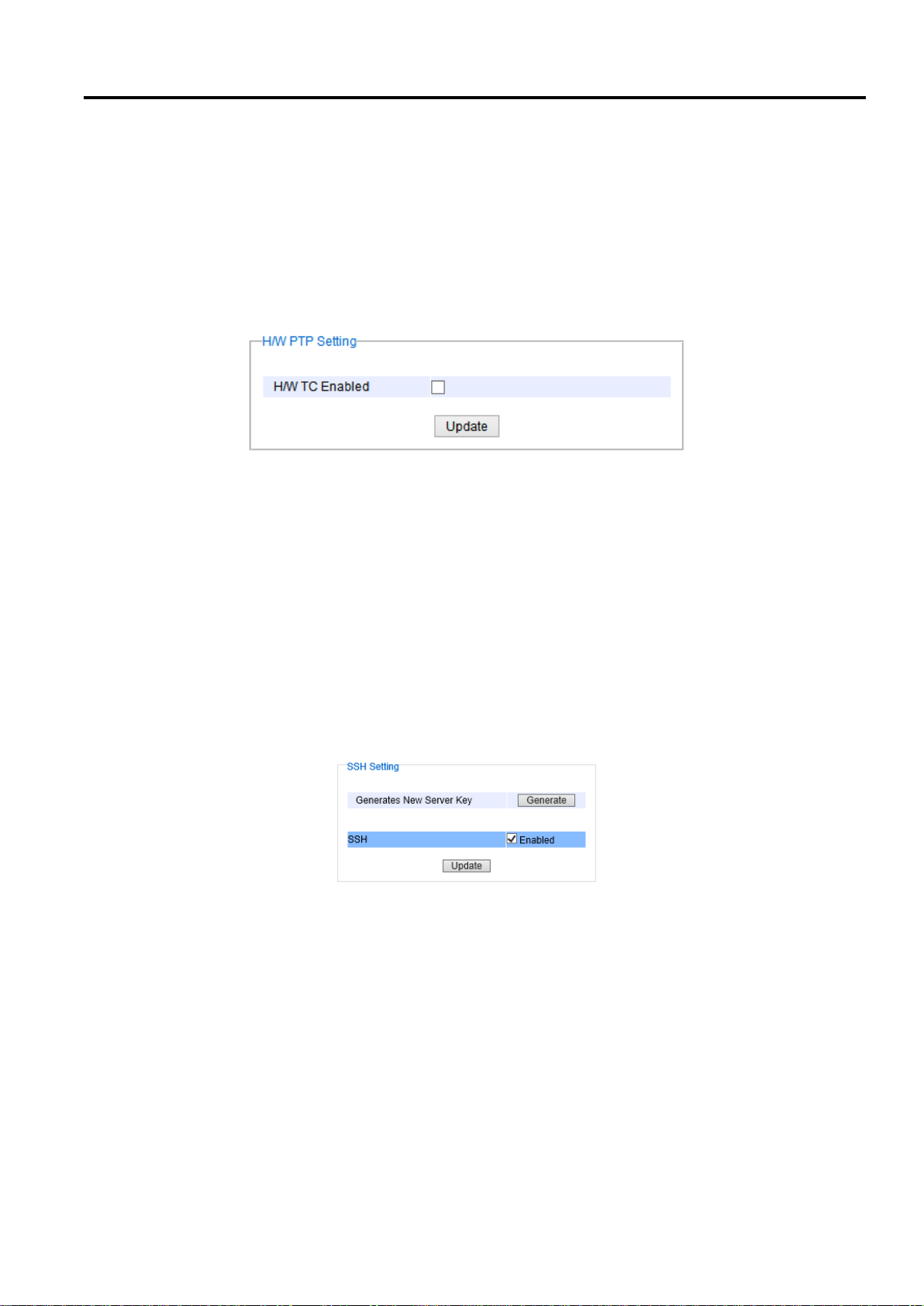
Industrial Managed
Ethernet Switch
User Manual
Configuring with a
Web Browser
2.3.9.2 Hardware PTP Setting
This subsection allows the user to enable the hardware Transparent Clock (TC). The TC can correct variable switch
latency. This can be done by measuring the time that a PTP event message has spent in the switch called residence
time. The residence time is reported to the receiver by the PTP event message itself. For this purpose, a new
message field has been added called Correction Field which is a type of time interval that can be used to
accumulate residence time along the path (possibly after multiple switches) of the message. To enable the
hardware transparent clock, check the box behind H/W TC Enabled and then click on the Update button as shown
in Figure 2.45.
Figure 2.45 Hardware PTP Setting
2.3.10 Secure Shell - SSH
The managed switch can be managed using command line interface (CLI) as described in Chapter 4. The users
have option to remotely connect to the managed switch using either secure shell (SSH) or Telnet through any of its
port. In this subsection, SSH will be introduced and then Telnet will be discussed in the next subsection. SSH was
designed to replace Telnet and other insecure remote shell protocols that sends data or command in plaintext. SSH
uses encryption to secure its data or command over an unsecure network.
To enable the SSH, please check the Enabled box behind the SSH option in Figure 2.46. At the beginning, the Server
will send a public key to a Client, and the Client will check if the received public key is correct. If it is not correct, the
Server will refuse the connection. Please click “Generate” button to change and regenerate the Server Key then
obtain another public key from Server as shown in Figure 2.46.
Figure 2.46 SSH Setting Webpage
Note:
1. The managed switch supports both SSH version 1 (SSH1) and SSH version 2 (SSH2).
2. The server key is re-generated when the managed switch is reset to its factory default setting or a received
key is non-existent.
SSH version 1 and SSH version 2 share the following features:
1. Client programs that use SSH can perform remote logins, remote command execution, and secure file
copying across a network.
2. Several selectable encryption algorithms and authentication mechanisms are supported by the SSH.
3. An SSH agent can cache keys for easy access in later session.
Page 44 of 190
Page 45
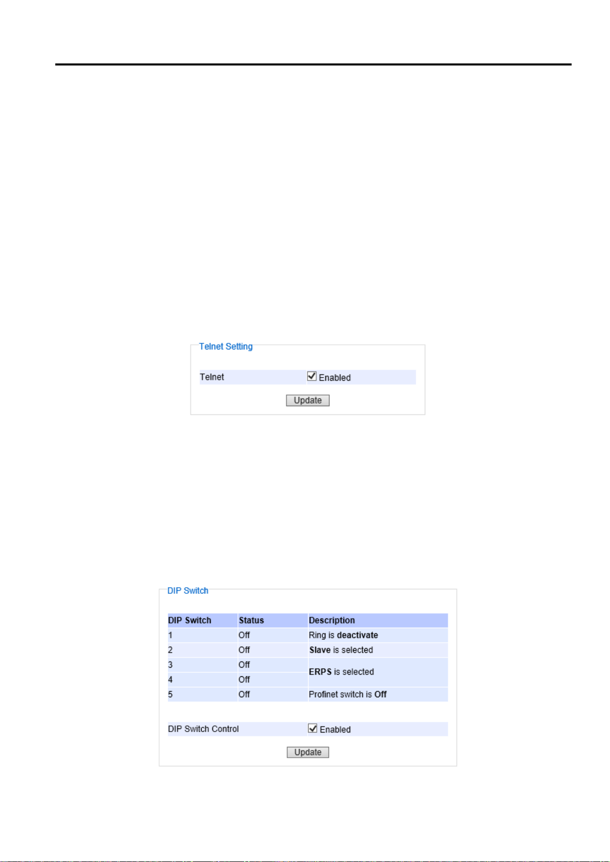
Industrial Managed
Ethernet Switch
User Manual
Configuring with a
Web Browser
A number of new features are added to SSH version 2 for a stronger and more comprehensive product. These
features include:
1. Encryption ciphers, i.e. Triple Data Encryption Standard (3DES) and Advanced Encryption Standard (AES).
2. The use of sound cryptographic Message Authentication Code (MAC) algorithms for integrity checking.
Examples of secure hash (functions) algorithms which are MAC algorithms in SSH version 2 are the
Message Digest algorithm 5 (MD5) and Secure Hash Algorithm 1 (SHA-1).
3. Support for public key certificates.
2.3.11 Telnet
This subsection allows the users to set the Telnet option for the managed switch. The command line interface (CLI)
configuration using Telnet (as described in Chapter 4) or SSH (previous section) are the same except that the SSH
encrypts the communication data. For the Telnet administration, the managed switch only provides the enable or
disable function selectable in this webpage. The default setting for Telnet is enabled. Clicking on the Update button
when you change the option to update it on the managed switch. Figure 2.47 shows the Telnet setting webpage.
Note that the users are recommended to use SSH instead of Telnet for higher security protection of your managed
switch.
Figure 2.47 Telnet Setting Webpage
2.3.12 DIP Switch
This subsection reports the status of the DIP switch on the top of managed switch’s housing.
Figure 2.48 shows the DIP switch webpage. The bottom portion allows the users to enable or disable the physical
control of the DIP Switch by checking on the DIP Switch Control option. This is another easy and convenient way
to configure ERPS or iA-ring or Compatible-Ring using the DIP Switches instead of modifying configuration on a
web browser. After checking or unchecking the option, please click Update button to allow the setting to take effect
on the managed switch.
Page 45 of 190
Figure 2.48 DIP Switch Status Webpage
Page 46
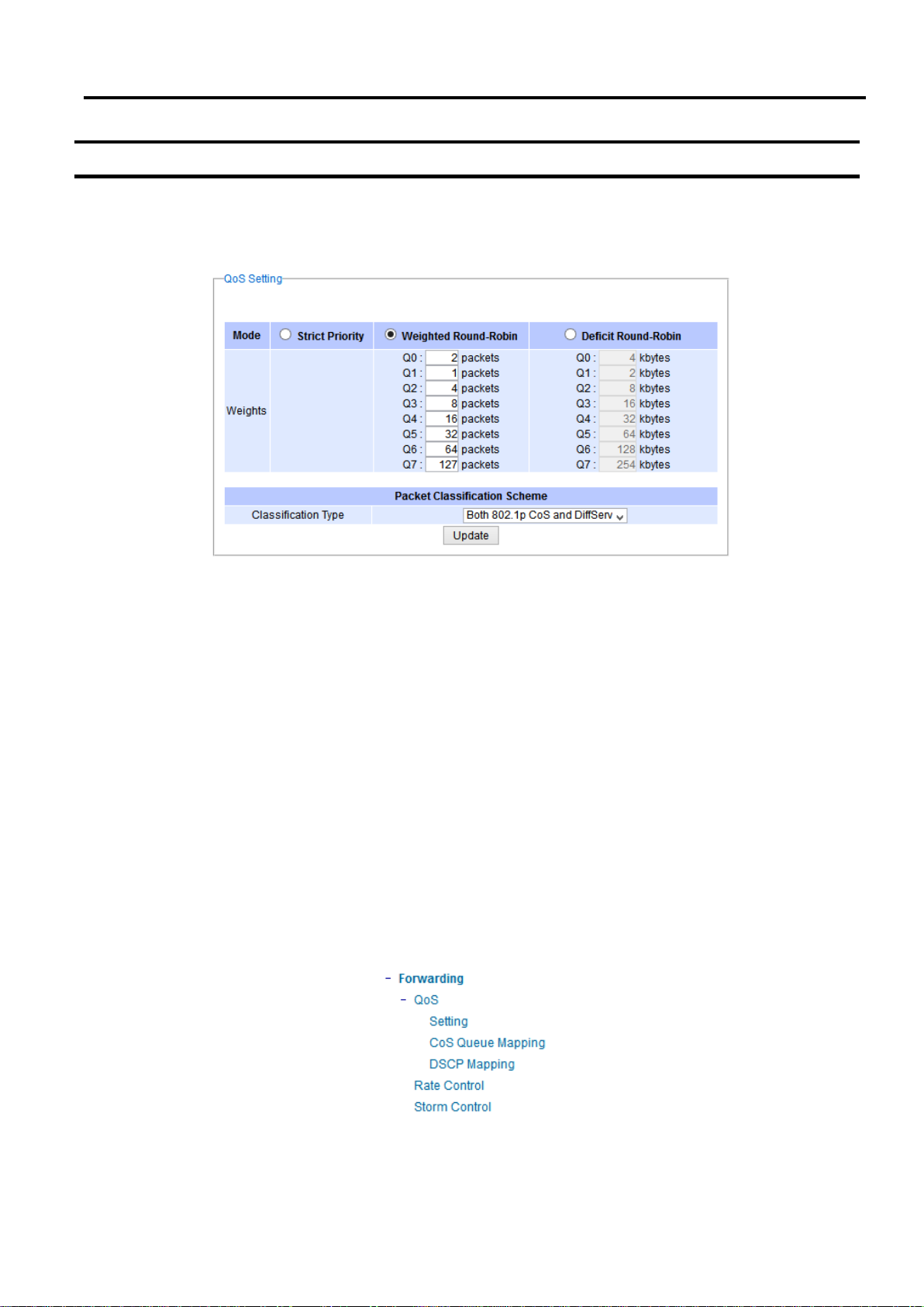
Industrial Managed
Ethernet Switch
User Manual
Configuring with a
Web Browser
2.4 Forwarding
There are many network technologies for forwarding packets over network. In this industrial managed switch, three
main technologies are implemented: QoS, rate control, and storm control. Figure 2.49 depicts the submenus under
the Forwarding section.
Figure 2.49 Forwarding Dropdown Menu
2.4.1 QoS
Quality of Service (QoS) is the ability to provide different priority to different applications, users, or data flows. QoS
guarantees a certain level of performance to a data flow by using the following metrics: transmitted bit rate, bit
error rate, delay, jitter, and probability of packet dropping. QoS guarantees are important if the network capacity is
insufficient, especially for application that requires certain bit rate and is delay sensitive. For any network that is
best effort, QoS cannot be guaranteed, except that resource is more than sufficient to serve users.
Controlling network traffic needs a set of rules to help classify different types of traffic and define how each of
them should be treated as they’re being transmitted. This managed switch can inspect both 802.1p Class of Service
(CoS) tags and DiffServ tags called Differentiated Services Code Point (DSCP) to provide consistent classification.
In the QoS section, three QoS mechanisms are included: queuing methods or packet scheduling disciplines in
Setting section, CoS Queuing Mapping section, and DSCP Mapping section, as shown in Figure 2.50. Table 2.12
summarizes the descriptions of QoS Setting.
Page 46 of 190
Figure 2.50 QoS Dropdown Menu
Page 47

Industrial Managed
Ethernet Switch
User Manual
Configuring with a
Web Browser
Label
Description
Factory Default
Setting
Queuing Methods (packet scheduling disciplines) includes Strict Priority,
Weighted Round-Robin, and Deficit Round Robin
See notes in the following subsection for detailed descriptions and comparison.
Strict Priority
Header
Mapping
CoS Queuing Mapping and DSCP Mapping
For 802.1p CoS only, switch only checks Layer 2 (L2) 802.1p CoS priority bits.
For DiffServ, switch checks DiffServ Code Point (DSCP). See notes below for a
detailed description.
Both 802.1p
CoS and
DiffServ
Table 2.12 Descriptions of QoS Setting
2.4.1.1 QoS Setting
Three types of queuing methods are configurable in this managed switch: Strict Priority, Weighted Round-Robin,
and Deficit Round-Robin.
In Strict Priority, the QoS scheduler allows the highest priority queue to preempt other queues as long as there are
still packets waiting to be transmitted in the highest priority queue. This mode guarantees that traffic in the highest
queue is always transmitted first. Only if the high priority queues are empty, the lower priority queues can be
transmitted. Queue 0 (Q0) to Queue 7 (Q7) are ranked from the lowest priority queue to the highest priority queue.
Therefore, packets in Q7 will be all transmitted first before packets in Q6, and packets in Q6 will all be sent first
before packets in Q5, and so on in this order.
Weighted Round Robin (WRR) is the simplest approximation of generalized processor sharing (GPS). In WRR, each
packet flow or connection has its own packet queue in a network interface controller. It ensures that all service
classes have access to at least some configured amount of network bandwidth to avoid bandwidth starvation. But
WRR has a limitation, as it is unfair with variable length packets. It only provides the correct percentage of
bandwidth to each service class only if all of the packets in all the queues are the same size or when the mean
packet size is known in advance. Usually, a weight of each queue is set proportion to requested bit rate. Each queue
is served proportionally to its weight for a service cycle.
Deficit WRR ( DWRR) addressed the limitation of WRR on unfairness over variable size. Each queue is configured
with a weight, a deficit counter ( total number of bytes that the queue is permitted to transmit each time visited by
the scheduler) , and a quantum of service ( bytes) . DWRR scans all non- empty queues in sequence. When a nonempty queue is selected, its deficit counter is incremented by its quantum value. Then, the value of the deficit
counter is the maximal number of bytes that can be sent at this turn. If the deficit counter is greater than the
packet’s size at the head of the queue, this packet can be sent and the value of the counter is decremented by the
packet size. Then the size of the next packets is compared to the counter value. Once the queue is empty or the
value of the counter is insufficient, the scheduler will skip to the next queue. If the queue is empty, the value of the
deficit counter is reset to 0. If the packet size is too small, the scheduler has to visit queues too many times before
serving a queue. But if the packet size is too large, some short term unfairness may arise. It is fair only over a time
scale longer than a round time. At the shorter time scale, some flows may get more service. Small packet size or
high transmission speed reduce the round time.
Figure 2.51 depicts the QoS Setting webpage. By default, the QoS in the managed switch works under the Strict
Priority mode. For Weighted Round Robin, packet weights of Q0 to Q7 are set in term of packet as followings.
- COS Q0 = 2 packets
Page 47 of 190
Page 48
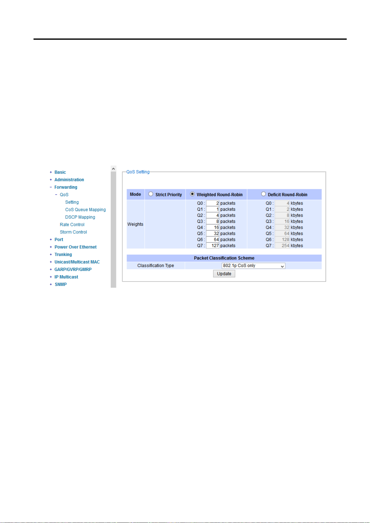
Industrial Managed
Ethernet Switch
User Manual
Configuring with a
Web Browser
- COS Q1 = 1 packet
- COS Q2 = 4 packets
- COS Q3 = 8 packets
- COS Q4 =16 packets
- COS Q5 = 32 packets
- COS Q6 = 64 packet
- COS Q7 = 127 packets
Weight of Deficit Round Robin is double the number of packets of WRR, but it is in term of Kbytes instead as
shown in the last column of Figure 2.51.
.
Figure 2.51 QoS Setting Webpage
At the bottom of the QoS Setting webpage in Figure 2.51, the users can select the packet classification scheme
that will be used by the managed switch. There are two classification types to choose from the drop-down list:
802.1p CoS only or Both 802.1p CoS and DiffServ. The default classification type is 802.1p CoS only. Note that
after changing the schedule discipline, setting the desired weights if any for the WRR or DWRR, or selecting the
classification type, please click on the Update button to enable them on the switch.
2.4.1.2 CoS Queue Mapping
802.1p CoS is the QoS technique developed by the IEEE P802.1p working group, known as Class of Service (CoS)
mechanism at Media Access Control (MAC) level. It is a 3-bit field called the priority code point (PCP) within an
Ethernet frame header (Layer 2) when using VLAN tagged frames as defined by IEEE 802.1Q. It specifies a priority
value between 0 and 7 that can be used by QoS to differentiate traffic. When this option is enabled, the switch
inspects the 802.1p CoS tag in the MAC frame to determine the priority of each frame.
The switch can classify traffic based on a valid 802.1p (CoS – Class of Service) priority tag. These options allow
users to map Priority Code Point (PCP) within an Ethernet frame header to different CoS priority queues as shown
in Figure 2.52. The user can choose the desired CoS Priority Queue from the drop-down list from Q1 to Q7 for
each PCP value. Descriptions of priority queue in CoS Queue Mapping page are summarized in Table 2.13.
Page 48 of 190
Page 49
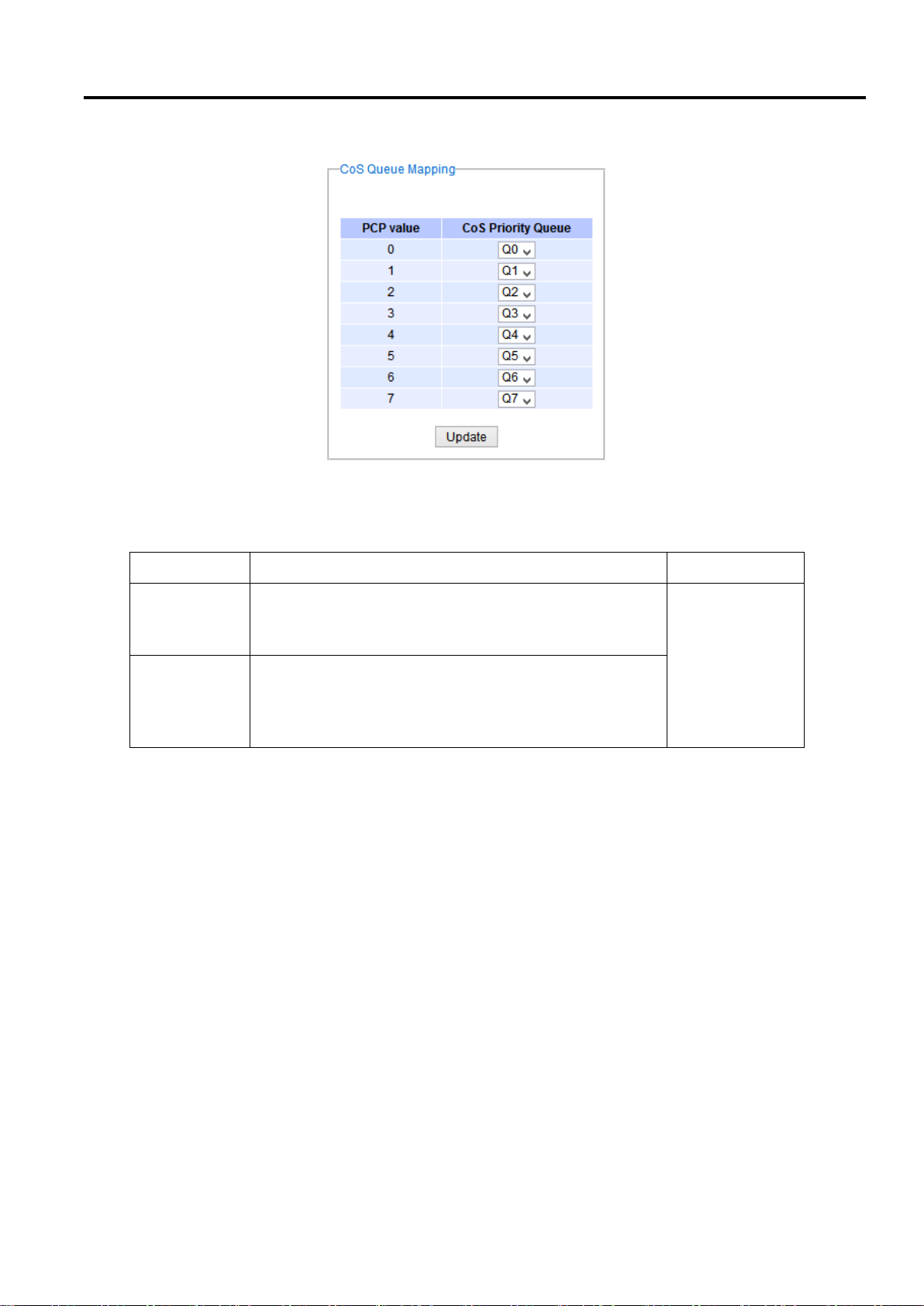
Industrial Managed
Ethernet Switch
User Manual
Configuring with a
Web Browser
Label
Description
Factory Default
PCP
Priority Code Point within the Ethernet frame header. PCP
0 is the lowest priority and 7 is the highest priority.
PCP 0 -> Q0
PCP 1 -> Q0
PCP 2 -> Q1
PCP 3 -> Q1
PCP 4 -> Q2
PCP 5 -> Q2
PCP 6 -> Q3
PCP 7 -> Q3
CoS Priority
Queue
The priority queue that a specific Ethernet frame needs to
be assigned into.
Figure 2.52 Mapping Table of CoS Webpage
Table 2.13 Priority queue descriptions
2.4.1.3 DSCP Mapping
DiffServ/ToS stands for Differentiated Services/Type of Services. It is a networking architecture that specifies a
simple but scalable mechanism for classifying network traffic and providing QoS guarantees on networks. DiffServ
uses a 6-bit Differentiated Service Code Point (DSCP) in the 8-bit differentiated services field (DS field) in the IP
header for packet classification purposes. The DS field and ECN field replace the outdated IPv4 TOS field in IPv4
to make per-hop behavior decisions about packet classification and traffic conditioning functions, such as
metering, marking, shaping, and policing.
The RFCs (Request for Comments) do not dictate the way to implement Per-Hop Behaviors (PHBs). Atop
implements queuing techniques that can base their PHB on the IP precedence or DSCP value in the IP header of a
packet. Based on DSCP or IP precedence, traffic can be put into a particular service class. Packets within a service
class are treated the same way.
DiffServ allows compatibility with legacy routers, which only supports IP Precedence, since it uses the DiffServ
Code Point (DSCP), which is the combination of IP precedence and Type of Service fields.
TOS (Type of Service) of the switch can be configured with the default queue weights as shown in Figure 2.53. Note
that the TOS consists of DSCP (Differentiated Service Code Point (6 bits)) and ECN (Explicit Congestion Notification
(2 bits)). The users can assign TOS values (DSCP) to predefined queue types (Priority) manually using DSCP
Mapping web page in Figure 2.53. The priority number can be between 0 to 7 where the number 7 is the highest
Page 49 of 190
Page 50
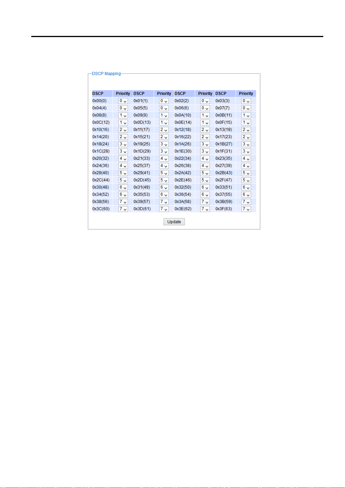
Industrial Managed
Ethernet Switch
User Manual
Configuring with a
Web Browser
priority and 0 is the lowest priority. After assigning any new priority to a DSCP, please click the Update button at the
bottom of the page to allow the new mapping to take effect.
Figure 2.53 Mapping Table of DSCP and ECN Webpage
2.4.2 Rate Control
The users have options to set the Rate Control for each port on the managed switch as shown in Figure 2.54. The
rate control mechanism will set a limit or maximum data rate which the port can transmit. Moreover, the rate control
can be imposed on both directions: the incoming traffic (Ingress) and the outgoing traffic (Egress). However, there
are some restrictions on the values that can be set on these two rate control parameters. Here is the summary of
the rules for Rate Control settings:
The outgoing (Egress) and incoming (Ingress) values have to be set between 0 and 102,400 (for 100 Mbps)
or 1,024,000 (for 1000 Mbps).
The value 0 is set to turn off the rate control mechanism.
The values have to be integer and multiple of 64 when the transmission rate is less than 1,792 Kbps. For
example: 64 Kbps, 128 Kbps, 512 Kbps, and 1,792 Kbps.
The values have to be integer and multiple of 1,024 when the transmission rate is between 1,792 Kbps and
102,400 Kbps (for 100Mbps) or 106,496 Kbps (for 1000M). Ex: 2,048Kbps, 3,072 Kbps… 102,400Kbps.
The values have to be integer and multiple of 8,192 when the transmission rate is greater than 106,496
Kbps.
Page 50 of 190
Page 51
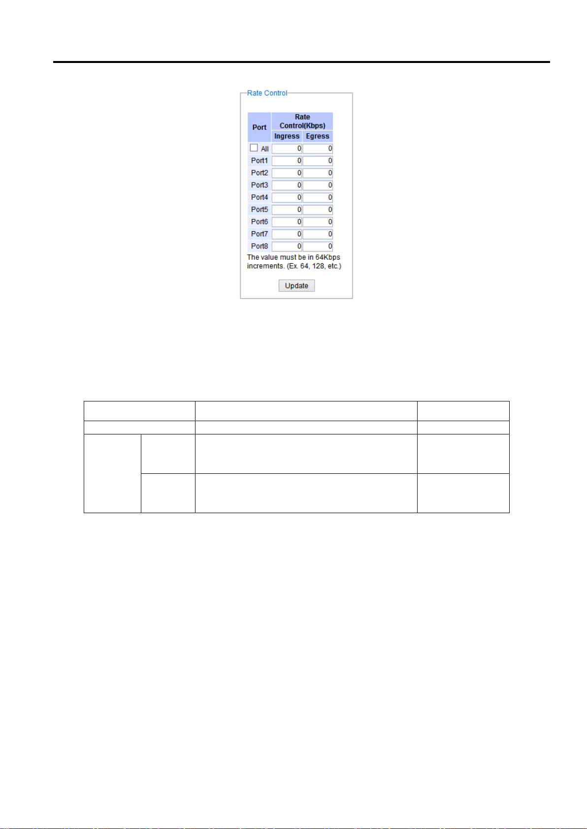
Industrial Managed
Ethernet Switch
User Manual
Configuring with a
Web Browser
Label
Description
Factory Default
Port
Port number on the managed switch.
-
Rate
Control
(Kbps)
Ingress
Sets limits on its transmission rates for the
incoming (Ingress) traffic. Note that the unit is
in kilo-bits per second (Kbps).
0 (Disabled)
Egress
Sets limits on its transmission rates for the
outgoing (Egress) traffic. Note that the unit is in
kilo-bits per second (Kbps).
0 (Disabled)
Figure 2.54 Rate Control Webpage
Table 2.14 provides descriptions of rate control setting. Note that after configuring the rate control in each port,
please click on the Update button to enable it on the switch.
Table 2.14 Descriptions of Rate Control Setting
2.4.3 Storm Control
This subsection provides the storm control or storm filter features of the managed switch. Storm control prevents
traffic on a LAN from being disrupted by ingress traffic of broadcast, multicast, and destination lookup failure (DLF)
on a port. Figure 2.55 depicts the Strom Control webpage. The users can impose the same limiting parameters on
all ports at the same time by clicking on the box in front of the all line and set the storm control data rate under
each limiting columns (DLF, Multicast, Broadcast). The storm control limiting can also be independently control on
each port. Note that the limiting value of 0 means that the storm control is disable and the value must be in multiples
of 64kbps. Additional ingress storm traffic will be dropped after the limit has reached.
Page 51 of 190
Page 52
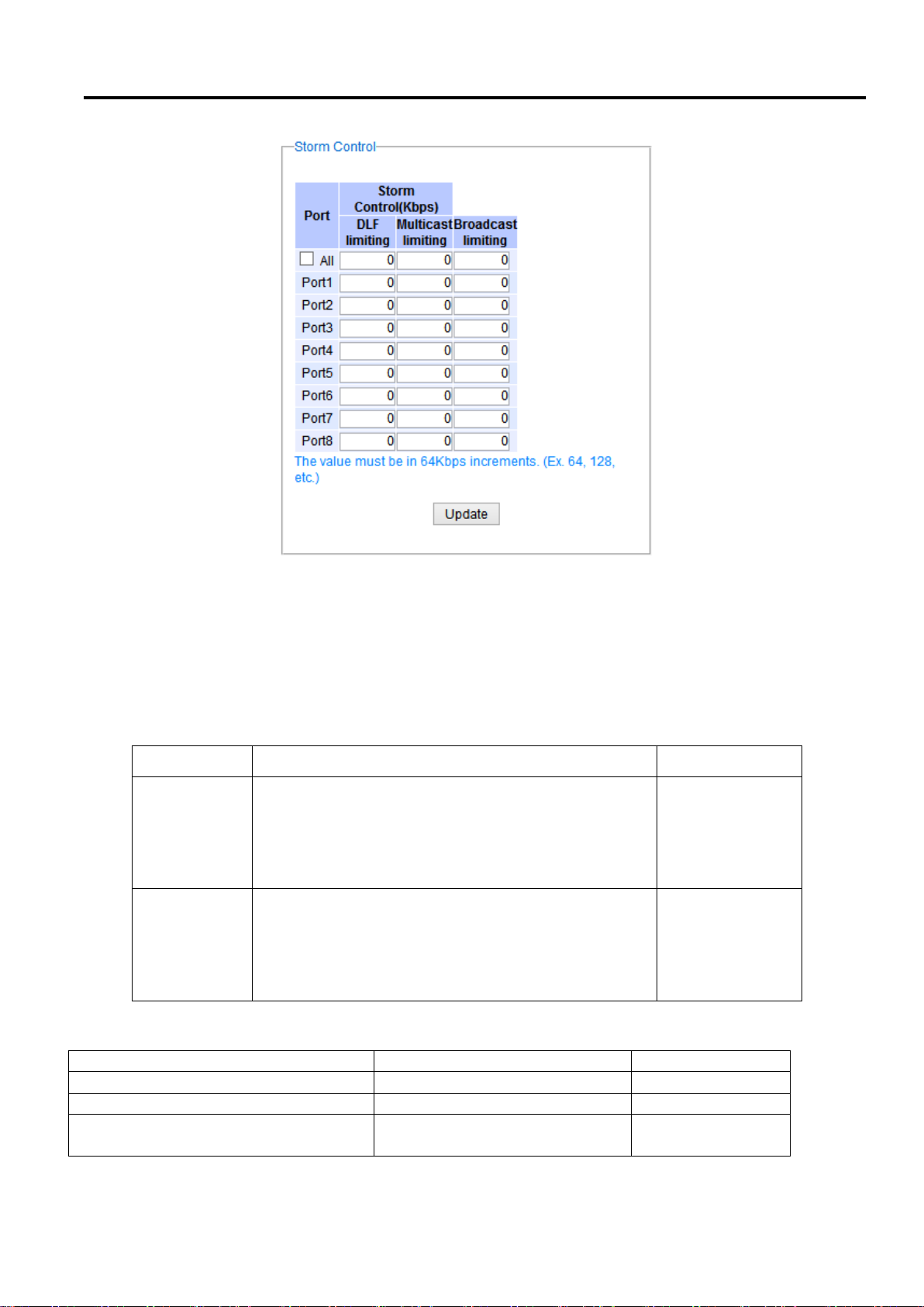
Industrial Managed
Ethernet Switch
User Manual
Configuring with a
Web Browser
Label
Description
Factory Default
All
Enable or Disable the storm control or filter on all ports
at the same time. The limiting data rate for each type of
storm packets (DLF, Multicast, and Broadcast) can be
controlled by changing the number under each column.
Note that the value must be in multiples of 64kbps.
Uncheck and
Disable
Port1 - Port8
Set the limiting data rate of storm packets that can be
controlled for each Port, which are DLF, Multicast, and
Broadcast. Note that the value must be in multiples of
64kbps. See notes below for the detailed description
and comparison.
Disable
Label
Description
Factory Default
DLF limiting (Destination Lookup Failure)
DLF limiting (0~9876480) Kb
0 (Disable)
Multicast limiting
Multicast limiting (0~9876480) Kb
0 (Disable)
Broadcast limiting
Broadcast limiting (0~9876480)
Kb
0 (Disable)
Figure 2.55 Storm Control Webpage
Table 2.15 summarizes the descriptions of storm control. Table 2.16 summarizes the descriptions of limiting
parameters for storm control.
Table 2.15 Descriptions of Storm Control
Table 2.16 Descriptions of Limiting Parameters
Page 52 of 190
Page 53
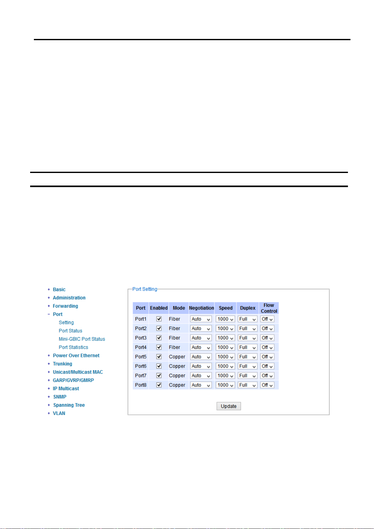
Industrial Managed
Ethernet Switch
User Manual
Configuring with a
Web Browser
Type of Storm Packets:
- DLF: Destination Lookup Failure. The switch will always look for a destination MAC address in its MAC Table
first. In case that a MAC address cannot be found in the Table, which means DLF occurs, the switch will forward
the packets to all ports that are in the same LAN.
- Multicast: This type of transmission sends messages from one host to multiple hosts. Only those hosts that
belong to a specific multicast group will receive it. Network devices that support multicast send only one copy
of the information across the network until the delivery path that reaches group members diverges. At these
diverging points, multicast packets will be copied and forwarded. This method helps reducing high traffic
volumes due to large number of destinations, using network bandwidth efficiently.
- Broadcast: Messages are sent to all devices in the network.
2.5 Port-related settings
Atop’s industrial managed switch provides full control on all of its network interfaces. In this section, the users can
enable or disable each port and set preferred physical layer mode such as copper or fiber. Moreover, the users will
be able to configure negotiation mechanism, data rate (speed), duplexing, and flow control for each port. All port’s
status and statistics can be viewed in this section. Figure 2.56 illustrates the Port webpage. The Port section is
subdivided into four subsections which are:
Port Setting
Port Status
Mini-GBIC Port Status
Port Statistics
Figure 2.56 Port Dropdown Menu
Page 53 of 190
Page 54

Industrial Managed
Ethernet Switch
User Manual
Configuring with a
Web Browser
2.5.1 Port Setting
Port Setting webpage is shown in Figure 2.57. The users can control the state of each port by checking on the
corresponding Enable box. The possible physical layer connections of each port are listed on the Mode column. In
some of Atop’s managed switches (EH75xx Series), the users can then select one of the physical media to be a
preferred mode of operation. For instance, a gigabit Ethernet port (PortG1) can support either copper or fiber
physical layer connections. The users can click on the radio button behind the Fiber option to set the fiber optical
mode as its preferred physical medium connection. Note that when both modes are selected, this means that the
port is a combo port. However, the example in Figure 2.57 is based on EHG7508-4PoE-4SFP which does not have
a combo port and cannot select preferred mode of operation.
Figure 2.57 Port Setting Webpage
Next on the fourth column of Figure 2.57, the users can select from the dropdown list the port’s Negotiation
mechanism which can be either Auto or Force. When selecting the Force negotiation, the port’s speed and
duplexing will be locked to the settings configured by the users. On the other hand, the Auto negotiation will allow
the switch to determine the actual speed and duplexing for that port. Note that the Gigabit Small Form-factor
Pluggable (SFP) Port of the EH Series switch is downward compatible with 125/155Mbps Transceivers; however,
the speed needs to be set to 100 manually. The Gigabit SFP Port of the EHG/EMG Series is not downward
compatible.
On the fifth column, the transmission Speed of each port can be chosen from the dropdown list which could be 10,
100, or 1000 Mbps. The default speed is set to the highest possible rate in Mbps. Next the port’s duplexing (Duplex)
can be either Full duplex or Half duplex. The Half duplex option allows one-way communication at a time, while the
Full duplex option allows simultaneous two-way communication.
Each port can set the Flow Control mechanism to either On or Off on the eighth column. This flow control will be
useful to avoid packet loss when there is a network congestion. However, the Flow Control setting is Off by default.
After configuring the port setting, please click on the Update button to enable any of your new configuration on the
switch. Descriptions of port setting options are summarized in Table 2.17.
Page 54 of 190
Page 55
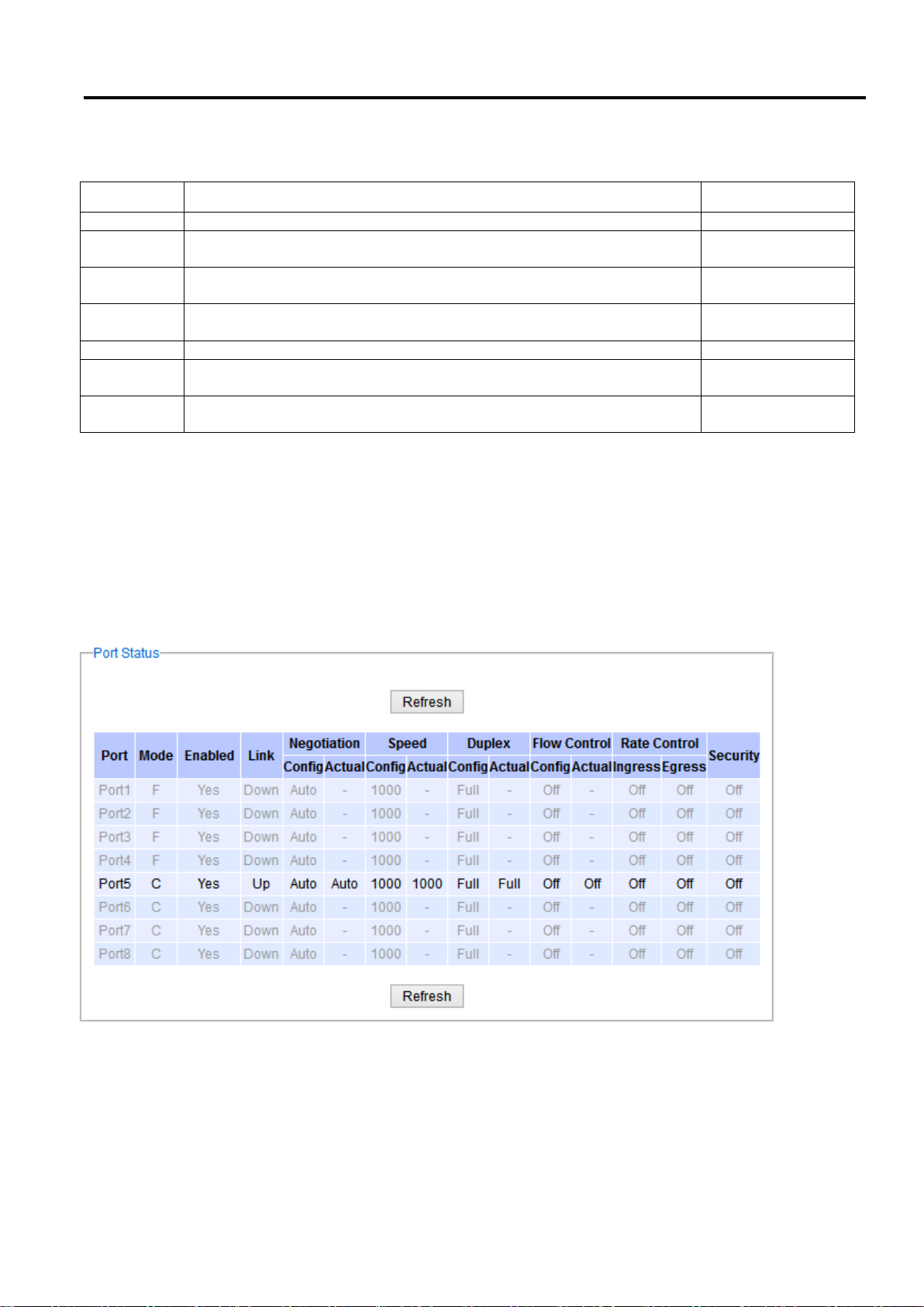
Industrial Managed
Ethernet Switch
User Manual
Configuring with a
Web Browser
Label
Description
Factory Default
Port
Port number on the managed switch.
-
Enable
Check the box to allow data to be transmitted and received through this
port
All ports are
enabled
Mode
Copper and/or Fiber modes. When both Copper and Fiber are listed, it
means that this is a Combo port
Depend
Negotiation
Choose from either Force or Auto.
See description in the paragraph above.
Auto-negotiation is
enabled to all ports.
Speed
Select either 10, 100, or 1000Mbps
Highest Speed
Duplex
Select either Half or Full Duplex. See description in the paragraph
above.
Full-Duplex
Flow
Control
Either on or off. The Flow Control mechanism can be enabled (On) to
avoid packet loss when congestion occurs.
Off
Table 2.17 Descriptions of Port Settings
2.5.2 Port Status
The overview of port status on the managed switch can be viewed in this webpage. The users can compare the
actual status and the configured options described in previous subsection for each port. The rate control (ingress
and egress) can be configured based on the instructions on Section 2.4.2. Figure 2.58 shows the Port Status
webpage. Note that the last column also reports the security status whether it is turned on or off on each port,
which can be either static security or 802.1x (See how to set security option for each port in Section 2.14). To check
the latest status of all port, click the Refresh button either on the top or the bottom of the webpage.
Figure 2.58 Port Status Webpage
The header in each column and its possible values of the ports’s status are listed here:
Mode (Copper (C) or Fiber (F))
Enable (Yes or No)
Link (Up or Down)
Page 55 of 190
Page 56
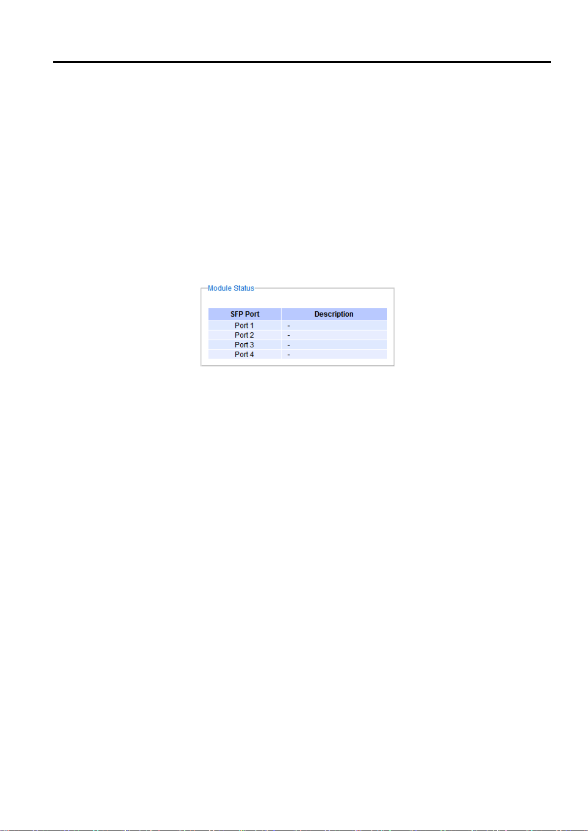
Industrial Managed
Ethernet Switch
User Manual
Configuring with a
Web Browser
Negotiation (Auto or Force)
Speed (unit: Mbps)
Duplex (Full or Half)
Flow Control (On or Off)
Rate Control (On or Off)
Security (On or Off): Either static security or 802.1x port security is turned on or off.
2.5.3 Mini-GBIC Port Status
The Small Form-factor Pluggable (SFP) port is sometimes referred to as a Mini-GBIC (Giga Bitrate Interface
Converter). In this subsection, all Mini-GBIC ports status can be shown if supported by the managed switch. Figure
2.59 depicts the Module (or Mini-GBIC Port) Status webpage. Note that the status here only provides the Ethernet
compliance codes and vendor name. The link status (up or down) can be viewed in the previous subsection.
Figure 2.59 Mini-GBIC Port Status Webpage
2.5.4 Port Statistics
The Port Statistics are summarized in this webpage as shown in
Figure 2.60. The users can use this subsection to help them diagnose the problem such as link quality of each port.
The key statistics are the total number of normal (OK) frames, the number of discarded (Error) frames, and the
speed of the transmission (Rate in Bps) for both transmitted (Tx) and received (Rx) traffic in each port. To clear or
reset all the statistics to zero on this page, click on the Clear button. To obtain the latest statistics on this page,
click on the Refresh button.
Page 56 of 190
Page 57
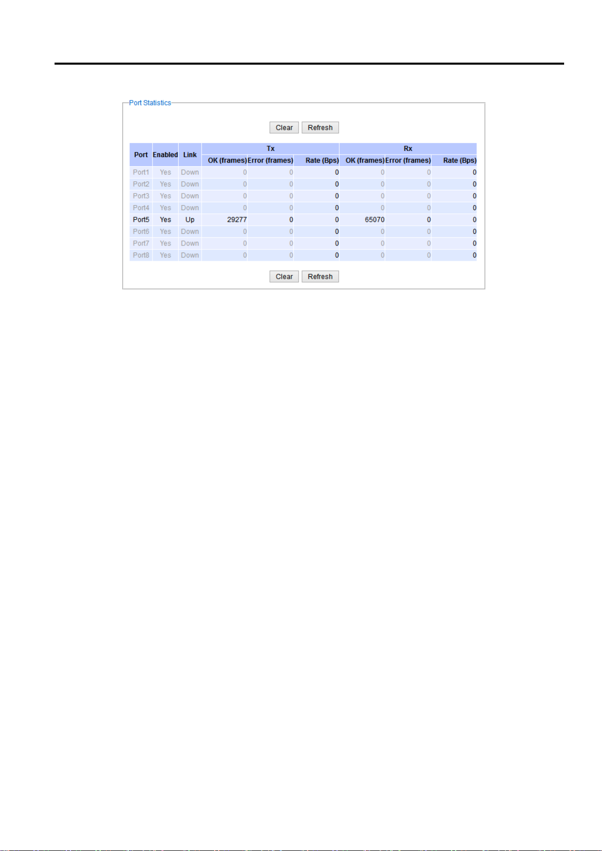
Industrial Managed
Ethernet Switch
User Manual
Configuring with a
Web Browser
Figure 2.60 Port Statistics Webpage
The header in each column and its possible values of the ports’s statistics are listed here:
Enable (Yes or No): The port is enabled (Yes) or disabled (No).
Link (Up or Down): Actual link status of the port.
Tx OK (frames): Total number of packets transmitted.
Tx Error (frames): The number of outbound packets which were chosen to be discarded even though no errors
have been detected to prevent them from being transmitted.
Tx Rate (Bps): Speed of transmission in Bytes per second.
Rx OK (frames): Total number of packets (not including faulty packets) received.
Rx Error (frames): Total number of faulty packets (including Oversize, Undersize, Frame Check Sequence (FCS),
Alignment, Jabber and Fragment Errors in packets) received.
Rx Rate (Bps): Receiving speed in Bytes per second.
Page 57 of 190
Page 58
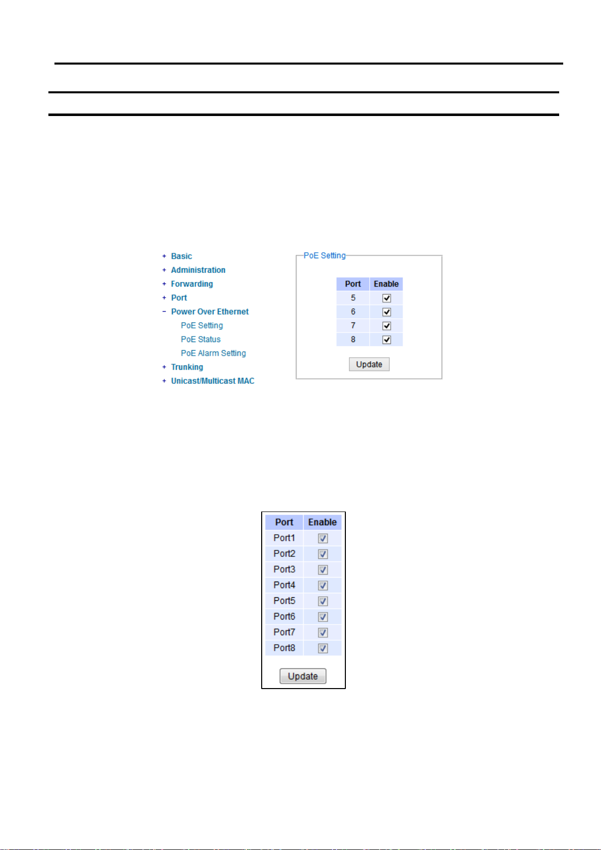
Industrial Managed
Ethernet Switch
User Manual
Configuring with a
Web Browser
2.6 Power over Ethernet
Power over Ethernet (PoE) is an optional function for the managed switches which enables the switch to provide
power supply to end devices called Powered Device (PD) connected on the other side of the Ethernet ports. This
means that the electrical power is delivered along with data over the Ethernet cables. This will be useful for the end
devices that are located in the area that has no power supply and the users can save additional wiring for the end
devices. To find out whether this function is supported or not by your managed switch, please look for the keyword
“PoE” in Atop’s model name. If the switch has “PoE” in its model name, it means that the switch is a Power Sourcing
Equipment (PSE) that can provide power output to a Powered Device (PD). Figure 2.61 shows the Power over
Ethernet dropdown menu.
Figure 2.61 Power over Ethernet Dropdown Menu example on EHG7508-4SFP-4PoE
2.6.1 PoE Setting
The PoE function for each port in the supported managed switch model can be set in this webpage as shown in
Figure 2.62. The users can check the Enable box for corresponding port. Please also click on the Update button to
allow the setting on PoE taking effect on the switch.
Page 58 of 190
Figure 2.62 PoE Setting Webpage example on EHG7508-8PoE
Note that the number of ports depends of the EHG model of the user’s managed switch.
Page 59
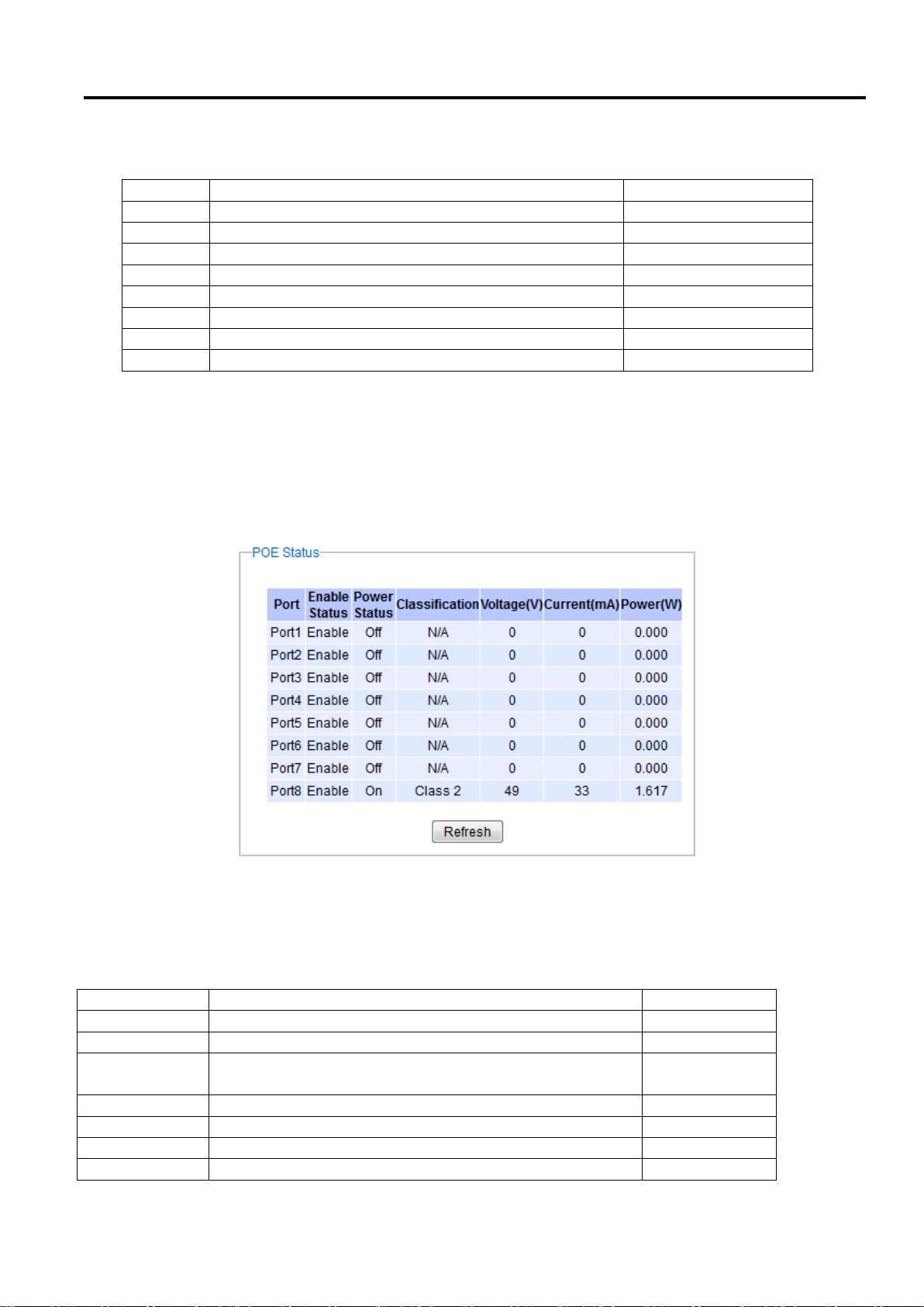
Industrial Managed
Ethernet Switch
User Manual
Configuring with a
Web Browser
Label
Description
Factory Default
Port1
Enable or Disable PoE function of the Port 1
Enable
Port2
Enable or Disable PoE function of the Port 2
Enable
Port3
Enable or Disable PoE function of the Port 3
Enable
Port4
Enable or Disable PoE function of the Port 4
Enable
Port5
Enable or Disable PoE function of the Port 5
Enable
Port6
Enable or Disable PoE function of the Port 6
Enable
Port7
Enable or Disable PoE function of the Port 7
Enable
Port8
Enable or Disable PoE function of the Port 8
Enable
Label
Description
Factory Default
Port
Port number
-
Enable Status
Enable or Disable PoE function
Enable
Power Status
On when there is a power device on the other end or Off
when there is no PD on the other end.
-
Classification
Display the classification of power device on the other end
-
Voltage (V)
Display the voltage supplied to this port in Volts
-
Current (mA)
Display the current supplied to this port in milli-Amperes
-
Power (W)
Display the power supplied to this port in Watts
-
Table 2.18 Descriptions of PoE Setting
2.6.2 PoE Status
This webpage summarizes the status of each PoE port. For example, in Figure 2.63, Port8 was enabled and is
supplying power to a Class 2 Powered Device (PD) indicated under the Classification column. The PD device is
rated at 49V and 33mA. The total power consumption for this PD is 1.617W. To check the status of the PoE port,
please click on the Refresh button. Table 2.19 provides descriptions of each column in the table of PoE Status.
Figure 2.63 PoE Status Webpage, example on EHG7508-8PoE
Table 2.19 Descriptions of PoE Status
Page 59 of 190
Page 60
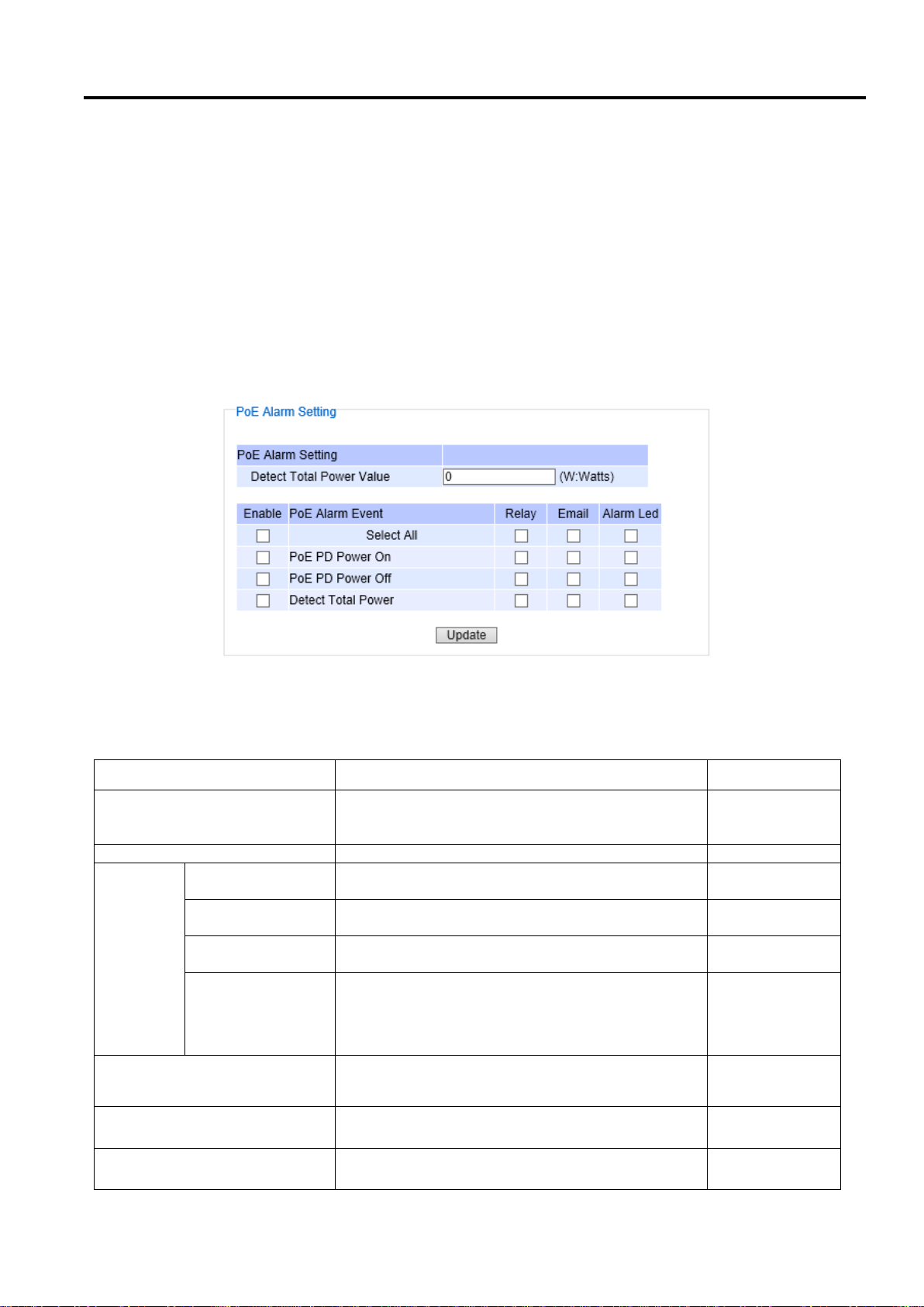
Industrial Managed
Ethernet Switch
User Manual
Configuring with a
Web Browser
Label
Description
Factory Default
Detect Total Power Value
Set the total power value in Watts which will trigger
alarm event. Note that the value ‘0’ means that the
alarm event will not trigger.
0
Enable
Check the box(s) to enable alarm event
Unchecked
PoE
Alarm
Event
Select All
Check the box in front of this option to enable all
alarm events
-
PoE PD Power On
Check the box in front of this option to enable alarm
event when PoE PD is power on.
-
PoE PD Power Off
Check the box in front of this option to enable alarm
event when PoE PD is power off.
-
Detect Total Power
Check the box in front of this option to enable
alarm event when managed switch can detect total
power exceeding the value set in the Detect Total
Power Value above.
-
Relay
Check the box in this column so that alarm will turn
on an external relay circuit.
Unchecked
Email
Check the box in this column so that alarm will
send out an email notification.
Unchecked
Alarm LED
Check the box in this column so that alarm will turn
on an external LED circuit.
Unchecked
2.6.3 PoE Alarm Setting
Alarm events can be set up to warn on unintended interruption in the PoE function or change(s) in status of the PoE
power device (PD) or exceeding of total power level set in this webpage. Figure 2.64 shows the PoE Alarm Setting
webpage in which the user can set the total power value in Watts that the managed switch can detect and trigger
an alarm. Then, the uses will have options to enable all alarm events or individual alarm event. There are three
categories of PoE Alarm Event listed here: PoE PD Power On, PoE PD Power Off, and Detect Total Power. The users
also have choices for notification of the alarm(s) by Relay, Email, or Alarm LED. The user can check the
corresponding box for each type of notification. Please refer to Table 2.20 for the descriptions of PoE Alarm Setting.
Note that the alarm events can also be found in the Event Log (when “Enabled” is checked - see explanation in
Section 2.20.1.2) or notified by Email (when “Email” is checked - see explanation in Section 2.20.2.2).
When “Relay”, “Alarm” and “Email” are checked, eventlog will show Warning/ Alarm log.
Figure 2.64 PoE Alarm Setting
Table 2.20 Descriptions of PoE Alarm Setting
Page 60 of 190
Page 61
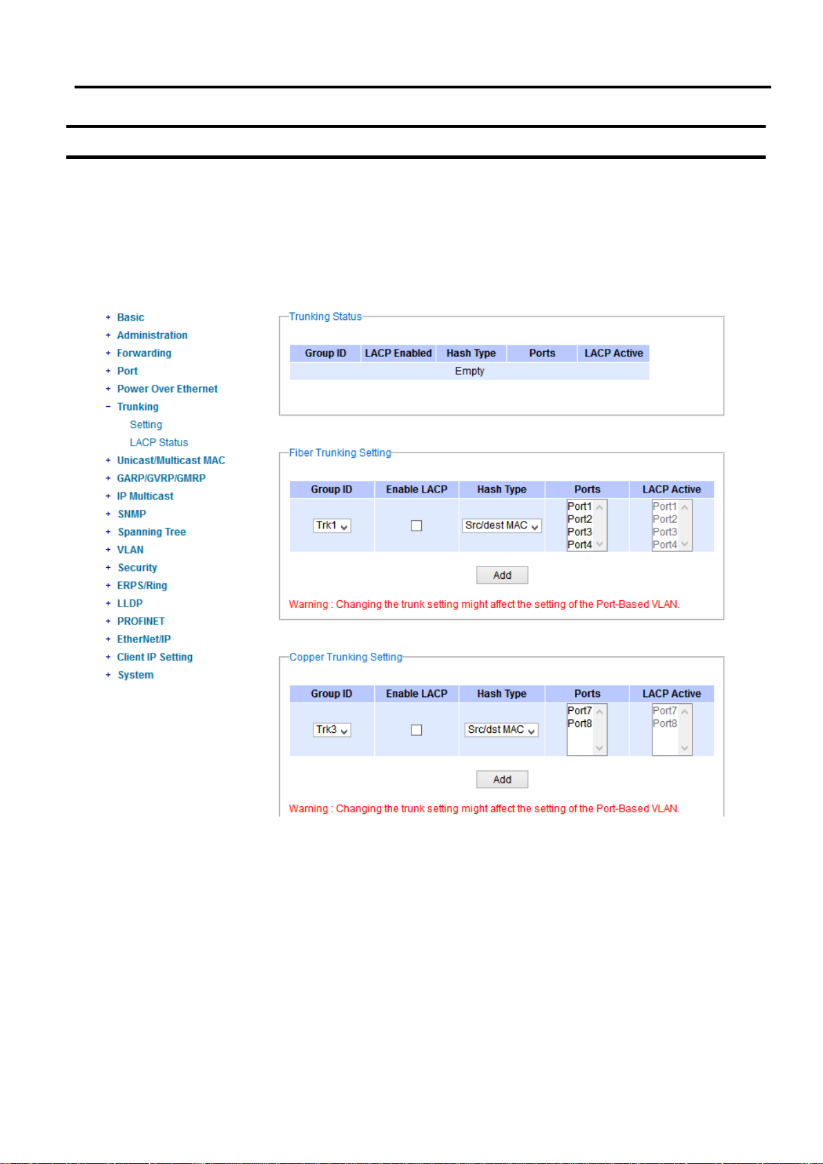
Industrial Managed
Ethernet Switch
User Manual
Configuring with a
Web Browser
2.7 Trunking
The managed switch supports Link Trunking, which allows one or more links to be combined together as a group
of links to form a single logical link with larger capacity. The advantage of this function is that it gives the users
more flexibility while setting up network connections. The bandwidth of a logical link can be doubled or tripled. In
addition, if one of links in the group is disconnected, the remaining trunked ports can share the traffic within the
trunk group. This function creates redundancy for the links, which also implies a higher reliability for network
communication. Figure 2.65 shows the Trunking dropdown menu.
2.7.1 Trunking Setting
In this subsection, the user can create new trunking assignment(s) and remove existing trunking assignment(s).
Figure 2.66 illustrates the Trunking Setting webpage. The top part of the page called Trunking lists existing trunk(s)
which can be removed by pressing the Remove button in the last column. Each line of the trunking provides
information about the group of links (Trunk) based on Group ID labeled with Trkx where x is the integer number
between 1 to 8. The managed switch can support up to 8 trunk groups. Note that for the difference media types
(for example Fast Ethernet, Gigabit Ethernet and Fiber), port trunking needs to be combined separately. Therefore,
Page 61 of 190
Figure 2.65 Trunking Dropdown Menu
Page 62
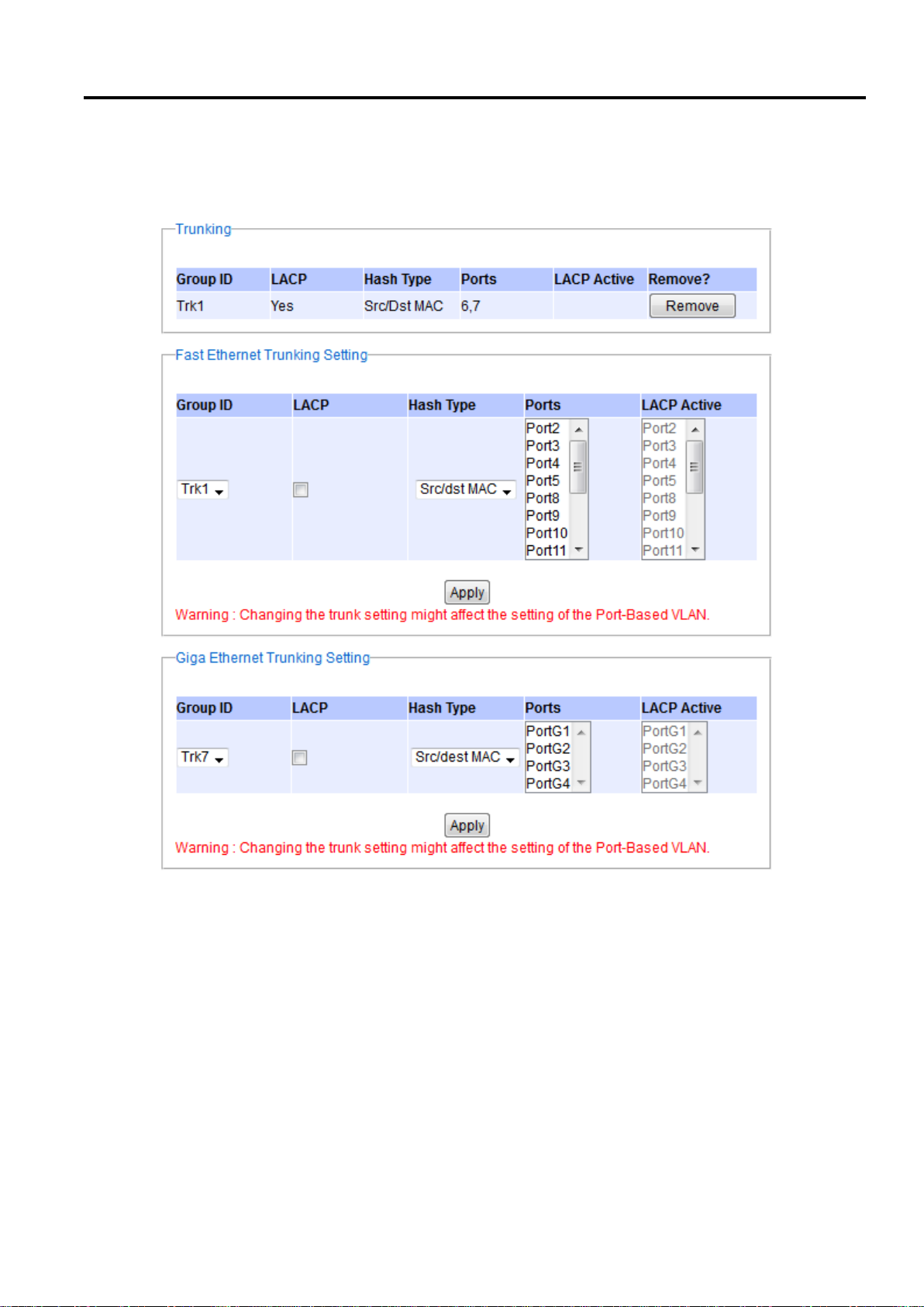
Industrial Managed
Ethernet Switch
User Manual
Configuring with a
Web Browser
there are two sections for creating trunking: Fast Ethernet Trunking Setting and Giga Ethernet Trunking Setting as
shown in the lower sections of the webpage.
The users have an option to enable Link Aggregation Control Protocol (LACP) which is an IEEE standard (IEEE
802.3ad, IEEE 802.1AX-2008) by checking on the box under the LACP column for each group. LACP allows the
managed switch to negotiate an automatic bundling of links by sending LACP packets to the LACP partner or
another device that is directly connected to the managed switch and also implements LACP. The LACP packets
will be sent within a multicast group MAC address. If LACP finds a device on the other end of the link that also has
LACP enabled, it will also independently send packets along the same links enabling the two units to detect multiple
links between themselves and then combine them into a single logical link. During the detection period LACP
packets are transmitted every second. Subsequently, keep alive mechanism for link membership will be sent
periodically. Each port in the group can also operate in either LACP active or LACP passive modes. The LACP active
mode means that the port will enable LACP unconditionally, while LACP passive mode means that the port will
enable LACP only when an LACP partner is detected. Note that in active mode LACP port will always send LACP
Page 62 of 190
Figure 2.66 Trunking Setting Webpage, example with EH7520
Page 63

Industrial Managed
Ethernet Switch
User Manual
Configuring with a
Web Browser
Label
Description
Group ID
Up to 8 trunk groups can be created: Trk1~Trk8. Note that it is
not possible to mix Fast Ethernet ports and Gigabit Ethernet
ports into the same trunk group.
LACP
Enable/Disable LACP (Link Aggregation Control Protocol). Brief
explanation of LACP is discussed in previous paragraph.
Hash Type
The hash result determines which port to use for a specific
frame. The available hash options are: Src MAC, Dst MAC,
Src/dst MAC, Src IP, Dst IP, and Src/dst IP.
Ports
Specify the member ports for this trunking group. Please hold
Control key to select more than one port at a time.
LACP Active
Specify which ports within the group should be in LACP Active
mode. The ports that are not selected will be in LACP Passive
mode.
Apply
Click Apply button to confirm the changes.
Remove
Click this button to remove any existing trunking group.
packets along the configured links. In passive mode however, LACP port acts as "speak when spoken to", and
therefore can be used as a way of controlling accidental loops (as long as the other device is in active mode). To
enable trunking over multiple ports, the users can follow the steps below:
Step 1: Select Trkx (x = 1 to 8) from Group ID dropdown list.
Step 2: Choose whether to enable LACP (IEEE standard, Link Aggregation Control Protocol).
Step 3: Select the Hash Type from the dropdown list.
Step 4: Select specific ports to be in this trunk group from the text box.
Step 5: Select specific ports in this trunk group to be LACP active.
Step 6: Click Apply button to set the configuration on the managed switch.
Descriptions of trunking settings are summarized in Table 2.21.
Table 2.21 Descriptions of Trunking Settings
2.7.2 LACP Status
Figure 2.67 lists the current switch’s trunking information. At the top of the page, the status of LACP on the
managed switch is reported whether it is enabled or disabled. Next, the users can also specify the system priority
here. LACP uses the system priority with the switch’s MAC address to form the system ID and also during
negotiation with its LACP partner. The LACP system ID is the combination of the LACP system priority value
(defined in this webpage) and the MAC address of the managed switch. The system priority determines which
managed switch makes the decisions on ports that will be bundled into a logical link. The lowest value determines
who has higher priority and is in charge. The table of LACP status provides information per port which are port
number, status of LACP, group ID, and LACP partner. Table 2.22 explains the descriptions of LACP status. To
change system priority, enter the desired number in the number box behind the system priority field and then click
Update button. To obtain the latest status of the LACP, click on the Refresh button.
Page 63 of 190
Page 64
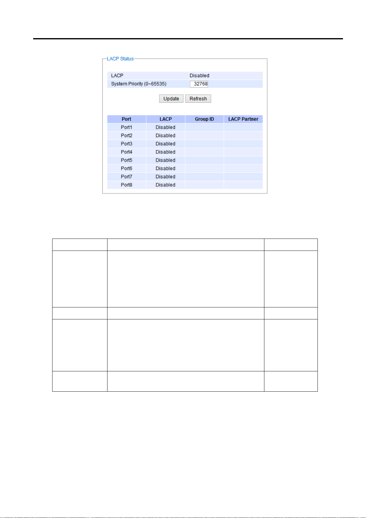
Industrial Managed
Ethernet Switch
User Manual
Configuring with a
Web Browser
Label
Description
Factory Default
System Priority
Indicate the system priority value of the managed
switch in the range of 1 ~ 65535. System priority is
used during the negotiation with other systems.
System priority and switch’s MAC address is used to
form a system ID.
Note that a higher number means a lower priority.
32768
Group ID
Show which trunk group that this port belongs to.
-
LACP
Disabled: LACP is disabled.
Passive: LACP will only passively respond to LACP
requests.
Active: LACP will be actively searching for LACP
Partner.
-
LACP Partner
Indicates whether a LACP Partner can be located on
the other side.
-
Table 2.22 Descriptions of LACP Status
Figure 2.67 LACP Webpage
Page 64 of 190
Page 65
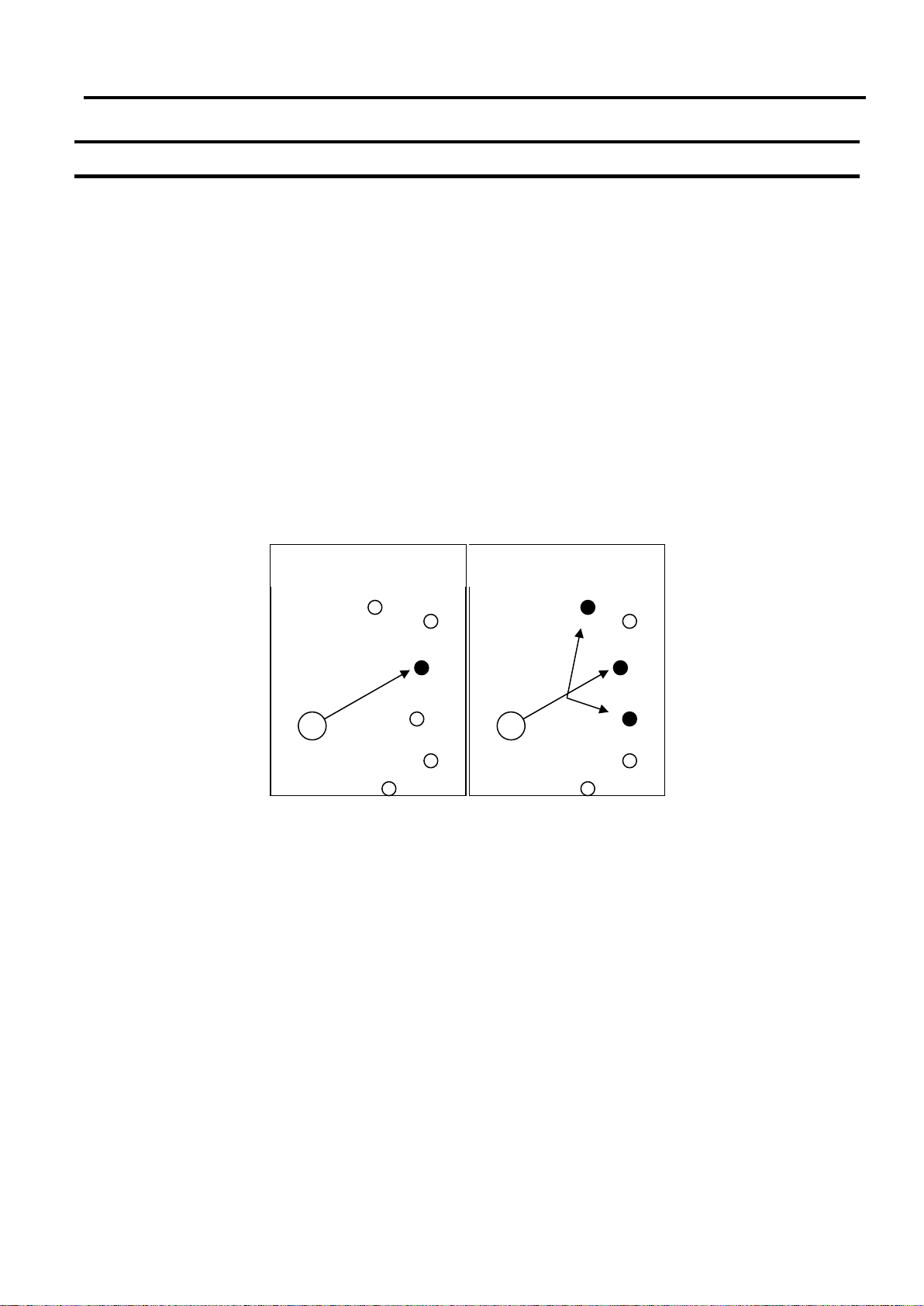
Industrial Managed
Ethernet Switch
User Manual
Configuring with a
Web Browser
Unicast
Multicast
2.8 Unicast/Multicast MAC
The managed switch is a network device which operate at the OSI layer 2 or medium access control (MAC) layer.
It forwards frames of OSI layer 2 based on the MAC addresses. Generally, the layer 2 switch will learn about the
destination MAC addresses of the end devices which are connected to the switch over time based on the
exchanged traffic. For instance, in the beginning if the switch does not know which port a destination MAC address
is, it will forward or broadcast a frame to all of its ports and wait for a response from end device connected to one
of the port. This way the switch will learn of the MAC address and corresponding port number. Later on, the switch
will forward the frame to the destination port only thus saving the traffic on other ports.
The managed switch typically maintains the learned MAC addresses in its memory which is usually called a MAC
Address table. In this section, the managed switch allows the users to control the MAC Address table by adding
static MAC addresses into the table or filtering certain MAC addresses so that they will not be forwarded by the
managed switch. Atop’s manage switch also provides the users with the ability to set the MAC address age-out
manually. Note that the age-out period is a duration of time that a learned MAC address will be maintained in the
MAC address table before it was removed to save the memory.
The MAC addresses that can be managed by the switch can be both Unicast and Multicast MAC addresses. This
section will briefly explain the concept of Unicast and Multicast forwarding as well as their benefits. Please see
Figure 2.68 for illustrations of the Unicast versus the Multicast concept.
Figure 2.68 Unicast vs. Multicast
Unicast: This type of transmission sends messages to a single network destination identified by a unique
MAC address. This method is simple with one source and one destination.
Multicast: This type of transmission is more complicated. It sends messages from one source to multiple
destinations. Only those destinations or hosts that belong to a specific multicast group will receive the
multicast packets. In addition, networks that support multicast send only one copy of the information across
the network until the delivery path that reaches group members diverges. At these diverging points, multicast
packets will be copied and forwarded. This method can manage high volume traffic with different destinations
while using network bandwidth efficiently. Multicast filtering improves the performance of networks that carry
multicast traffic.
Figure 2.69 shows the Unicast/Multicast dropdown menu which allows the users to manage and view the status of
MAC address table.
Page 65 of 190
Page 66
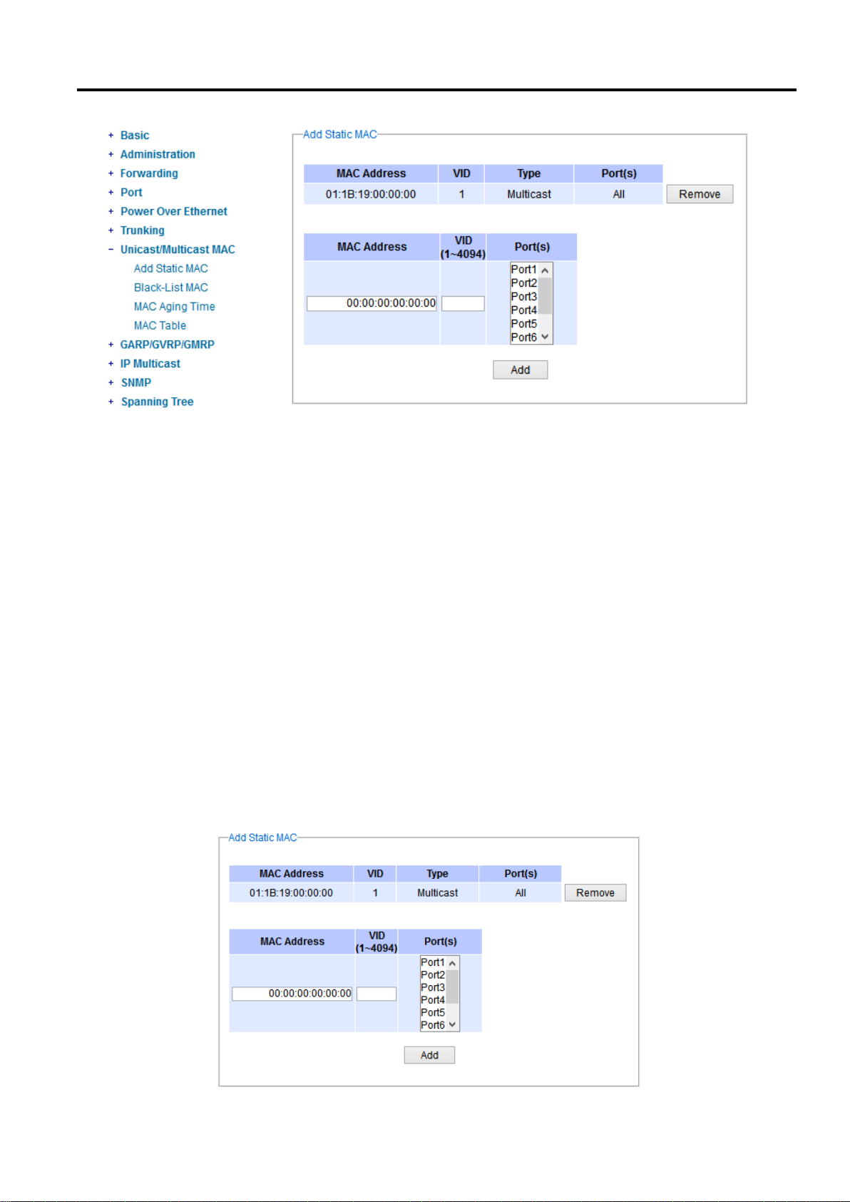
Industrial Managed
Ethernet Switch
User Manual
Configuring with a
Web Browser
Figure 2.69 Unicast/Multicast Dropdown Menu
2.8.1 Add Static MAC
The managed switch allows the users to manually add static MAC addresses into its memory. The static MAC
addresses will enable the managed switch to forward the traffic based on the MAC addresses in its memory to the
destination port with specific virtual local area network (VLAN) identification (VID). Following the simple steps here
to add a static MAC address.
Step 1: Enter a MAC Address which can be either Unicast or Multicast MAC Address.
Step 2: Specify VLAN ID (VID).
Step 3: Select the ports to apply this static MAC address. Use Ctrl-key to add more than one port.
Step 4: Click on Add button.
Figure 2.70 depicts the Add Unicast/Multicast MAC webpage. There is an example of a table of static MAC address
in the upper part of the webpage where the last column of the table has Remove buttons for each entry. The users
can remove any existing static MAC address by clicking on the Remove button. The lower part of the webpage is
where the user can enter a new static MAC address along with its VLAN ID (VID) as outline by the procedure above.
Table 2.23 summarizes the fields in this Add Static MAC webpage.
Page 66 of 190
Page 67
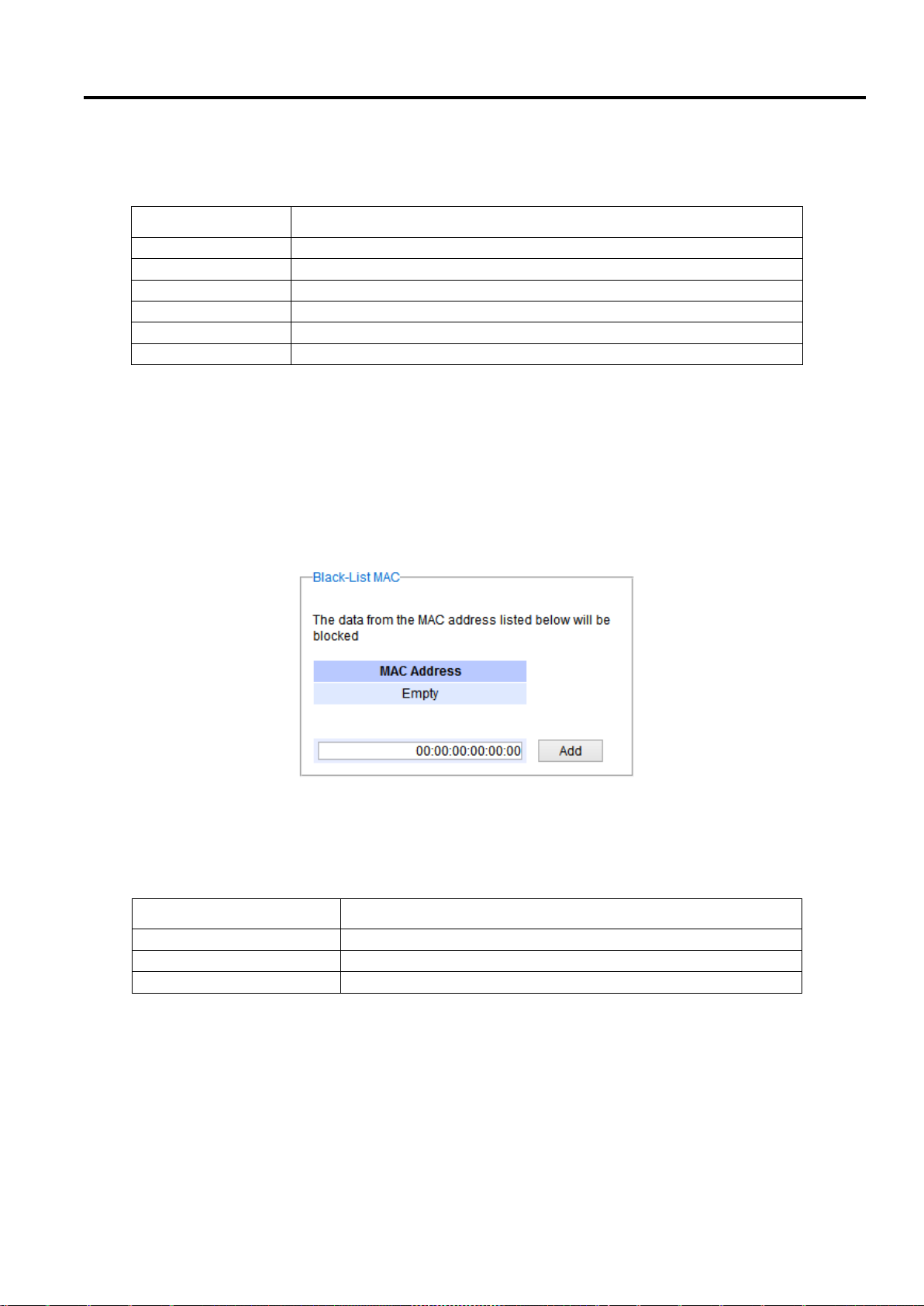
Industrial Managed
Ethernet Switch
User Manual
Configuring with a
Web Browser
Label
Description
MAC address
Enter a MAC address manually.
VID
Specify VLAN ID that this static MAC belongs to. (1 – 4096)
Type
Multicast or Unicast MAC address.
Port(s)
Define which ports to apply this static MAC address.
Add
Confirm and add the MAC address by clicking on this button
Remove
Click on this button to remove existing static MAC address in the table.
Label
Description
MAC Address
Enter MAC address to be black-listed or filtered manually.
Remove
Remove the corresponding entry in MAC filtering table.
Add
Add a MAC addresses to the MAC filtering table
Figure 2.70 Add Static MAC Webpage
Table 2.23 Description of fields in Add Static MAC Webpage
2.8.2 Black-List MAC
As discussed earlier, the managed switch also allows users to set MAC filtering manually. Figure 2.71 show the
Black-List MAC webpage. The upper part of the page is the table of existing filtered MAC address where the users
can remove the filter by clicking on the Remove button on each entry. The lower part of the page is where a new
source MAC address that the users would like to filter can be entered into the MAC filtering table (black-list). Table
2.24 summarizes the fields in the MAC Filter webpage.
Figure 2.71 Black-List MAC Setting Webpage
Table 2.24 Descriptions of MAC Filtering Webpage
2.8.3 MAC Aging Time
This function allows users to set MAC address age-out or aging time manually as shown in Figure 2.72. The users
can specify the Age-out Time between 0 and 600 seconds in the following field. Note that the default value of ageout time is 300 seconds. In the managed switch, a MAC address table is stored in the memory to map a MAC
address and a port number to forward frames. The aging time is the duration of time to keep MAC addresses in the
MAC address table. For a longer aging time, the learned MAC address will stay in the memory longer. As a result,
Page 67 of 190
Page 68
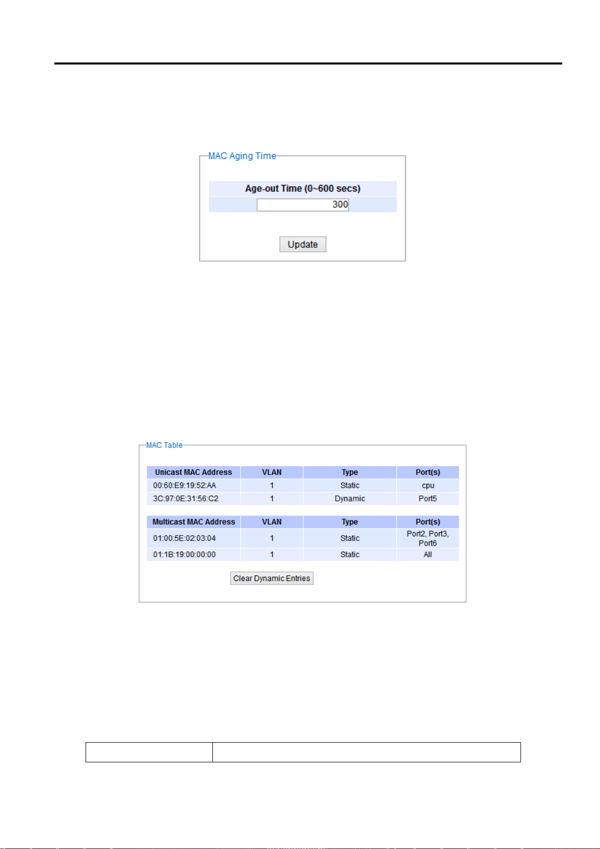
Industrial Managed
Ethernet Switch
User Manual
Configuring with a
Web Browser
Label
Description
the switch will be able to forward the frames to a specific port quickly instead of forwarding to all the ports to
prevent frame flooding. A shorter aging time will allow the switch to free up the old MAC addresses in the table to
learn new MAC addresses. This will be useful when there are large number of MAC addresses (or end devices) in
the network and when the traffic between any two end devices are short-lived.
Figure 2.72 MAC Aging Time Webpage
2.8.4 MAC Table
Information of current Unicast and Multicast MAC addresses in the memory (MAC Table) of the managed switch
is displayed in this webpage as shown in Figure 2.73. The list of Unicast MAC addresses is shown first and follows
by the list of Multicast MAC addresses. If there are more entries to be displayed, the users can click on the Next
Page button to see other entries. The users also have an option to clear dynamic entries in the MAC address table
by clicking on the Clear Dynamic Entries button at the bottom of the webpage. The descriptions of the MAC Address
table are summarized in Table 2.25.
Figure 2.73 MAC Table Webpage
Note: the static multicast address can be set from “Add Static MAC” (Section 2.8.1) in “Unicast/Multicast MAC”
(Section 2.8) or from “Static IP Multicast” (Section 0) in “IP multicast” (Section 0).
Page 68 of 190
Table 2.25 Descriptions of MAC Address Table
Page 69

Industrial Managed
Ethernet Switch
User Manual
Configuring with a
Web Browser
Unicast/Multicast MAC
Displays MAC address.
VLAN
Displays VLAN ID.
Type
Displays whether the MAC address is dynamic or static. Note that
dynamic is the address that is learned automatically, while static
is the address that is entered by the users.
Ports
Displays which port that this MAC address belongs to.
Clear Dynamic Entries
Clears all Dynamic MAC addresses by clicking this button.
Next Page
Clicking on this button to continue to the next page when there are
more MACs available.
Page 69 of 190
Page 70
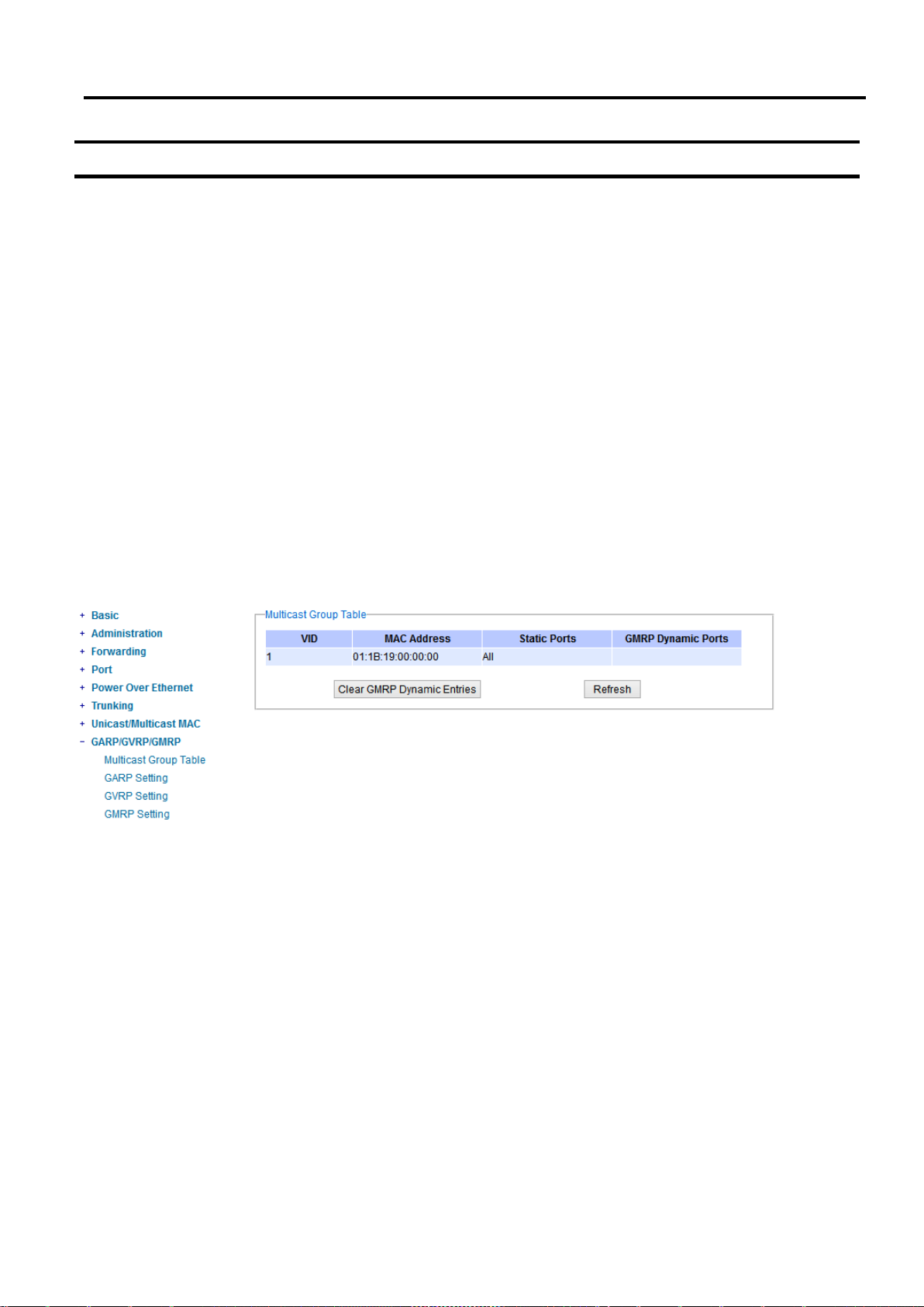
Industrial Managed
Ethernet Switch
User Manual
Configuring with a
Web Browser
2.9 GARP/GVRP/GMRP
This page includes three options, GARP, GVRP, and GMRP settings. Main concept of all three protocols are to
eliminate unnecessary network traffic by preventing transmission/retransmission to unregistered users. These
functions are enabled by default. They can only be disabled if no MAC addresses are added in the multicast group
table.
GARP: Generic Attribute Registration Protocol, previously called Address Registration Protocol, is a LAN protocol
that defines procedures by which end stations and switches can register and de-register attributes, such as network
identifiers or addresses with each other. Every end station and switch thus has a record, or list, of all the other end
stations and switches that can be reached at a given time. Specific rules are used to modify set of participants in
the network topology, or so called reachability tree.
GVRP: GARP VLAN Registration Protocol. GVRP is similar to GARP, but work with VLAN instead of other network
identifiers. It provides a method to exchange VLAN configuration information with other devices, and conforms to
IEEE 802.1Q.
GMRP: GARP Multicast Registration Protocol provides a mechanism that allows bridges (or switches in this case)
and end stations to dynamically register group membership information with the MACs of bridges (switches)
attached to the same LAN segment and for that information to be disseminated across all bridges (switches) in
the Bridged (switched) LAN that supports extend filtering services. GMRP provides a constrained multicast flooding
facility similar to IGMP snooping. The difference is that IGMP is IP-based while GMRP is MAC-based.
Figure 2.74 GARP/GVRP/GMRP Dropdown Menu
2.9.1 Multicast Group Table
In this subsection, the list of MAC addresses which were dynamically registered by GMRP into the Multicast
Group Table can be viewed. The multicast group table in Figure 2.75 displays the following information for each
MAC Address: VLAN ID (VID), Static Port(s), and GMRP Dynamic Port(s). The user can clear the table by clicking
Page 70 of 190
Page 71
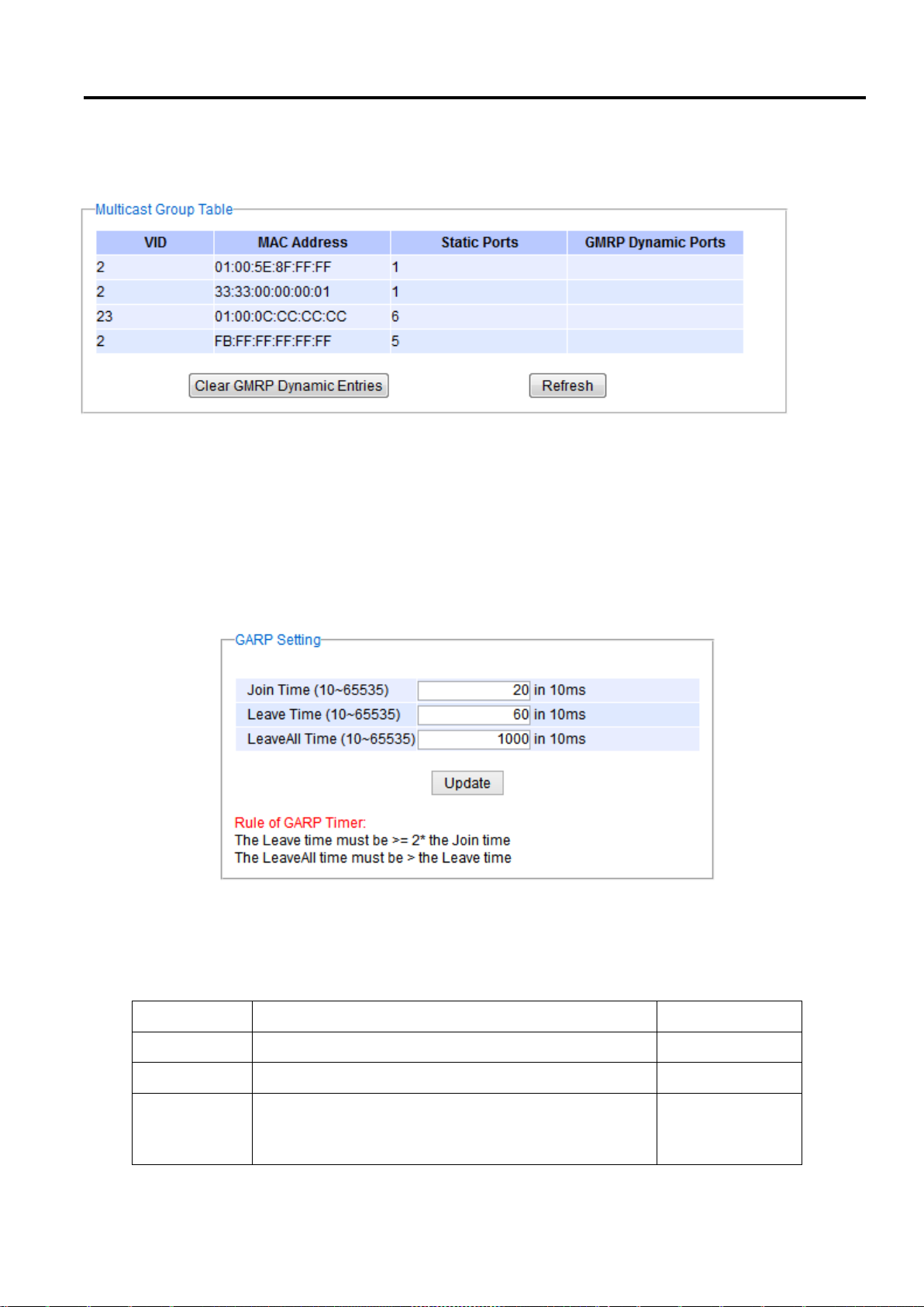
Industrial Managed
Ethernet Switch
User Manual
Configuring with a
Web Browser
Label
Description
Factory Default
Join Timer
Indicates the GARP Join timer, in 0 ~ 65535 seconds.
200 milliseconds
Leave Timer
Indicates the GARP Leave timer, in 0 ~ 65535 seconds.
600 milliseconds
Leave All
Timer
Indicates the GARP Leave All timer, in 0 ~ 65535
seconds.
10000
milliseconds or 10
seconds
on the Clear GMRP Dynamic Entries button or obtain the latest update on the table by clicking on the Refresh
button.
Figure 2.75 Multicast Group Table
2.9.2 GARP Setting
Figure 2.76 shows GARP Setting webpage where different Timers (Join, Leave, and LeaveAll) can be set. All devices
that are exchanging attributes must set these timers to the same values. Note that the GARP Timer values are in
multiple of 10 milliseconds. Table 2.26 summarized the descriptions and values of all Timers for GARP setting.
Please click the Update button after setting your new values.
Figure 2.76 GARP Setting Webpage
Table 2.26 Descriptions of GARP Timer Settings
Page 71 of 190
Page 72
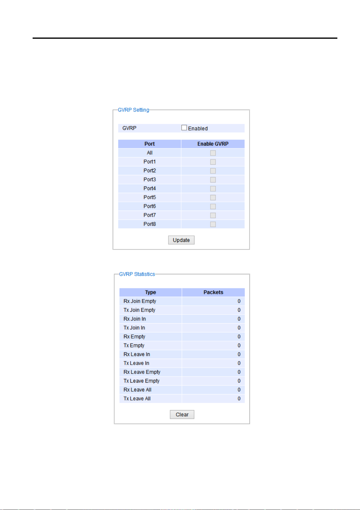
Industrial Managed
Ethernet Switch
User Manual
Configuring with a
Web Browser
2.9.3 GVRP Setting
In this section, GVRP can be enabled on the switch and then it can be enabled for all ports or specific port(s) and
trunking group(s). The multicast IP address with designated VLAN ID can be accessed from each ports. Figure 2.77
and Figure 2.78 below illustrate GVRP Setting and Statistics. When GVRP is enabled, the switch which is an end
node of a network needs to add static VLANs locally. Others switches can dynamically learn the rest of the VLANs
configured elsewhere in the network via GVRP.
Figure 2.77 GVRP Setting Box with Port Enabling
Figure 2.78 GVRP Statistics
To enable GVRP in Figure 2.77, check the Enabled’s box and then select the desired port(s) by flagging the
corresponding checkbox(es). Please click Update button to save the change to the switch. Figure 2.78 provides
Page 72 of 190
Page 73
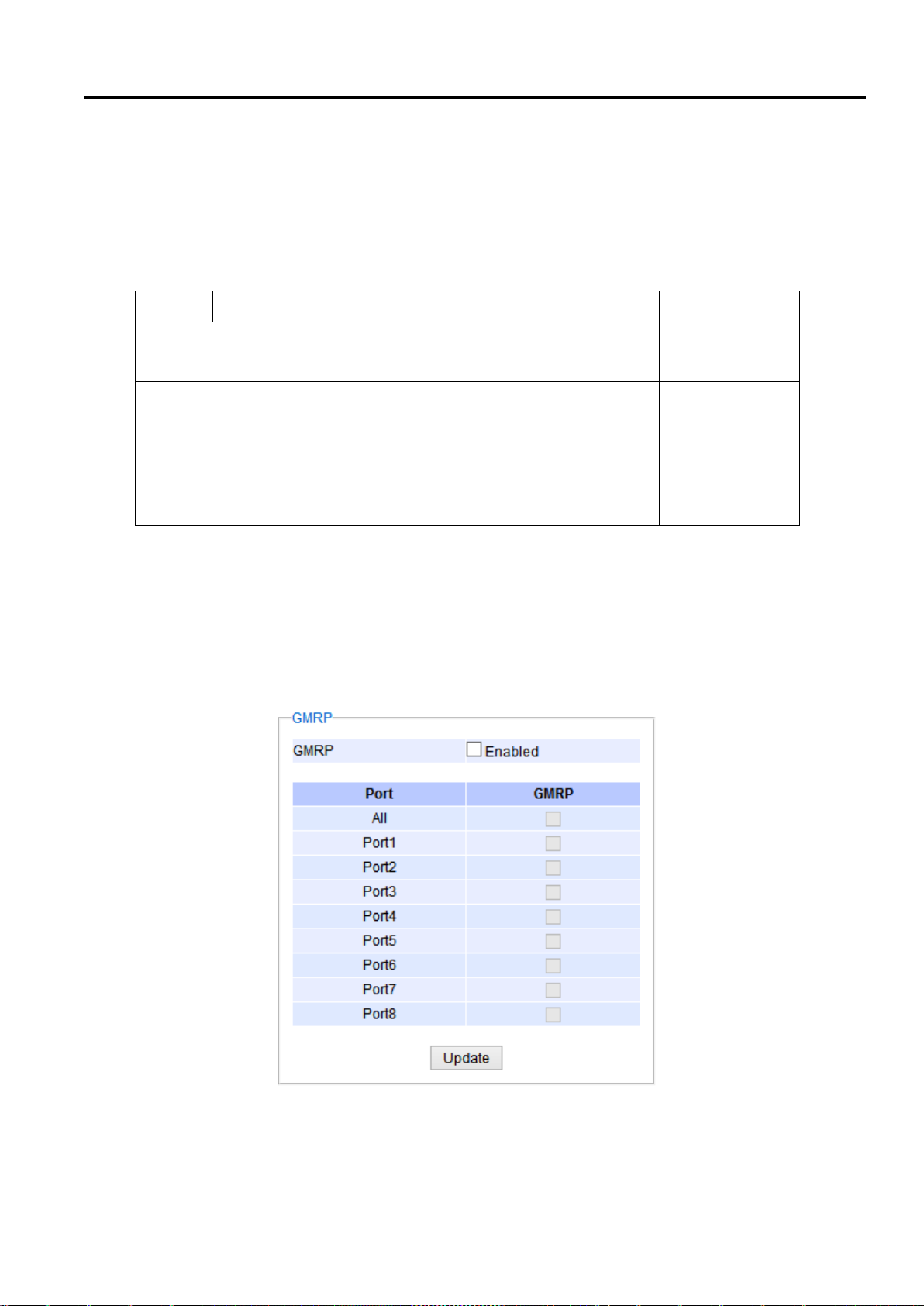
Industrial Managed
Ethernet Switch
User Manual
Configuring with a
Web Browser
Label
Description
Factory Default
GVRP
Enables or disables GVRP protocol.
Enables GVRP, the switch must be in 802.1q VLAN mode.
Disabled
Port
Enables or disables GVRP on each port. If users have already
defined trunking group (e.g. Trk1), it can also be selected to
be enabled. If you check the All Port’s box, all ports will be
enabled.
All ports are
disabled
Clear
Statistics
Clears all GVRP statistics counts
Clears the record
summarized statistics on the packet count of GVRP based on the following packet types: Rx Join Empty, Tx Join
Empty, Rx Join In, Tx Join In, Rx Empty, Tx Empty, Rx Leave In, Tx Leave In, Rx Leave Empty, Tx Leave Empty, Rx
Leave All, and Tx Leave All. To clear the statistics on this table, please click on the Clear button at the bottom of
the table. Table 2.27 describes the GVRP setting’s options.
Table 2.27 GVRP Setting Descriptions
2.9.4 GMRP Setting
The users can use this subsection to enable GMRP and enable GMRP for all ports or specified port(s) and trunking
group(s) as shown in Figure 2.80. To enable GMRP in Figure 2.79, check the Enabled’s box and then select the
desired port(s) by flagging the corresponding checkbox(es). Please click Update button to save the change to the
switch.
Figure 2.79 GMRP Setting Box
Page 73 of 190
Page 74
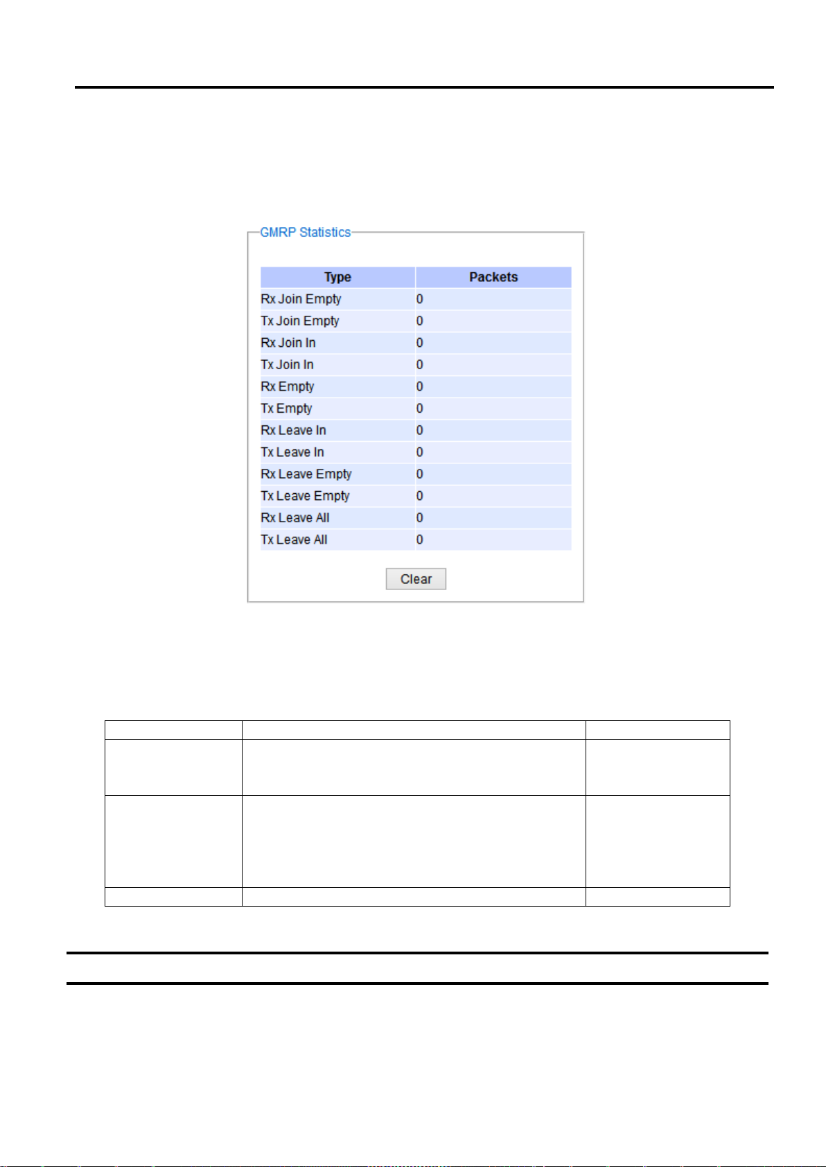
Industrial Managed
Ethernet Switch
User Manual
Configuring with a
Web Browser
Field
Field Description
Factory Default
GMRP
You can enable or disable GMRP by enabling the
checkbox. To enables GMRP, the switch must be
in 802.1q VLAN mode.
Disabled.
Port
You can enable or disable GMRP on specified ports
by clicking the corresponding checkbox. If you have
already defined trunking group (e.g. Trk1), you can
also enable it. If you check the All Port’s box, all ports
will be enabled.
All Ports are
disabled.
Clear Statistics
You can clear all GMRP Statistics
Clears the records
The GMRP Statistics can also be viewed on the bottom of this page as shown in Figure 2.80. The GMRP Statistics
provides summarized statistics on the packet count of GMRP based on the following packet types: Rx Join Empty,
Tx Join Empty, Rx Join In, Tx Join In, Rx Empty, Tx Empty, Rx Leave In, Tx Leave In, Rx Leave Empty, Tx Leave Empty,
Rx Leave All, and Tx Leave All. To clear the statistics on this table, please click on the Clear button at the bottom of
the table. Table 2.28 briefly describes GMRP setting and statistics.
Figure 2.80 GMRP Statistics
Table 2.28 Descriptions of GMRP Settings and Statistics
2.10 IP Multicast
The managed switch supports Internet Group Management Protocol (IGMP) which is a communication protocol
used on IP version 4 networks to establish multicast group memberships among switches in the network. IGMP is
an integral part of IPv4 multicast. It operates above the network layer of OSI model. One of the most important
features related to this protocol is IGMP snooping, which is supported by the managed switch and greatly
Page 74 of 190
Page 75
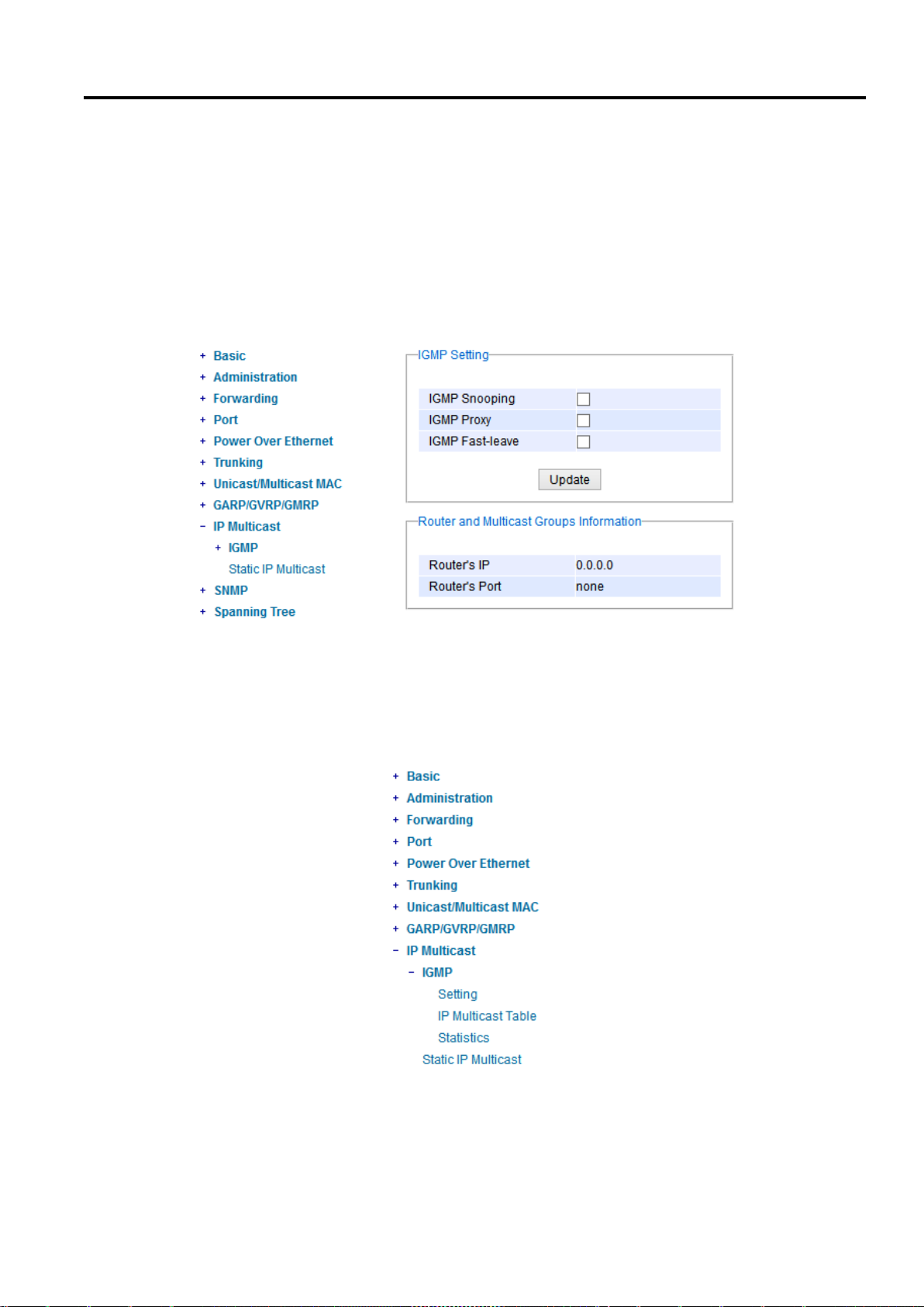
Industrial Managed
Ethernet Switch
User Manual
Configuring with a
Web Browser
strengthens network functionality. The IGMP snooping is a process of “listening” to IGMP network traffic. By
listening to conversations between different devices, it maintains a map of links and IP multicast streams. This
means that multicast traffic may be filtered from the links of the managed switch which do not need them.
Therefore, IGMP snooping enables the managed switch to only forward multicast traffic to the links that have
requested it. This section contains two submenus as shown in Figure 2.83Figure 2.81 which are:
IGMP
Static IP Multicast
Figure 2.81 IP Multicast Dropdown Menu
2.10.1 IGMP
The IGMP (Internet Group Management Protocol) submenu is further divided into three options which are: Setting,
IP Multicast Table, and Statistics. Figure 2.82 shows the three options under the IGMP submenu.
Figure 2.82 IGMP's Options
Page 75 of 190
Page 76
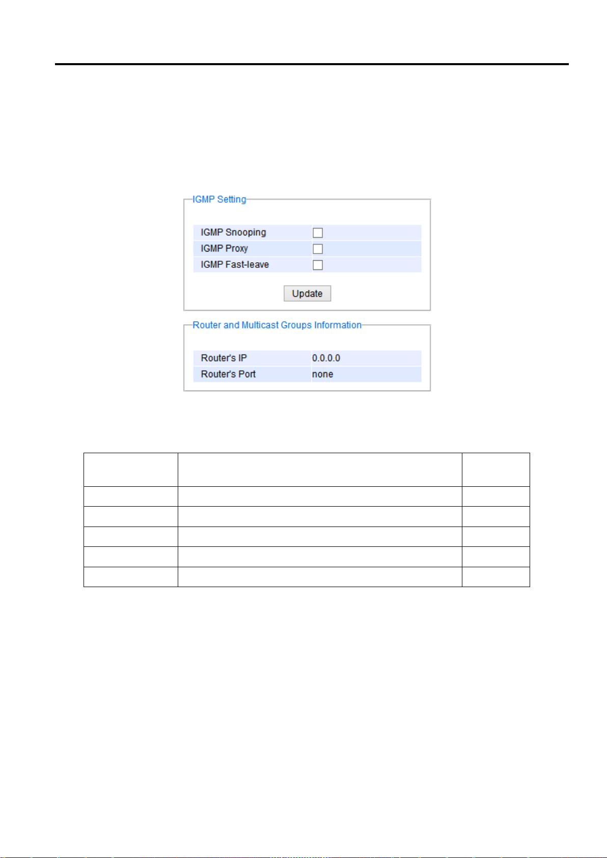
Industrial Managed
Ethernet Switch
User Manual
Configuring with a
Web Browser
Label
Description
Factory
Default
IGMP Snooping
Check the box to enable IGMP snooping.
Disabled
IGMP Proxy
Check the box to enable IGMP proxy. See note below.
Disabled
IGMP Fast-leave
Check the box to enable IGMP Fast-leave. See note below.
Disabled
Router's IP
Display the multicast router’s IP address.
-
Router's Port
Display the port that is connected to multicast router.
-
2.10.1.1 IGMP Settings
This webpage allows the users to set IGMP features on the managed switch as shown in Figure 2.83. There are
three features that can be enabled: IGMP Snooping, IGMP Proxy, and IGMP Fast-leave. After checking the desired
feature’s boxes, please click on the Update button to allow the options to take effect. The lower part of the page
lists Router and Multicast Groups Information which are router’s IP and port information. Table 2.29 summarizes
the descriptions of IGMP’s Settings.
Figure 2.83 IGMP Setting Webpage
Table 2.29 Descriptions of IGMP’s Settings
*NOTE:
IGMP Proxy works as an intermediate server, as shown in Figure 2.84. When it receives a membership query
message from the router, it sends a membership report message to the router port. When it receives a
membership report message from a computer in a new multicast group, it sends a membership report message
back to the router port. When it receives a leave group message from a computer which is the only one in the
group, it sends a leave group message to the router port and removes the computer from multicast group. Proxy
is like a middle man that handles information about multicast group in between routers and computers.
Page 76 of 190
Page 77
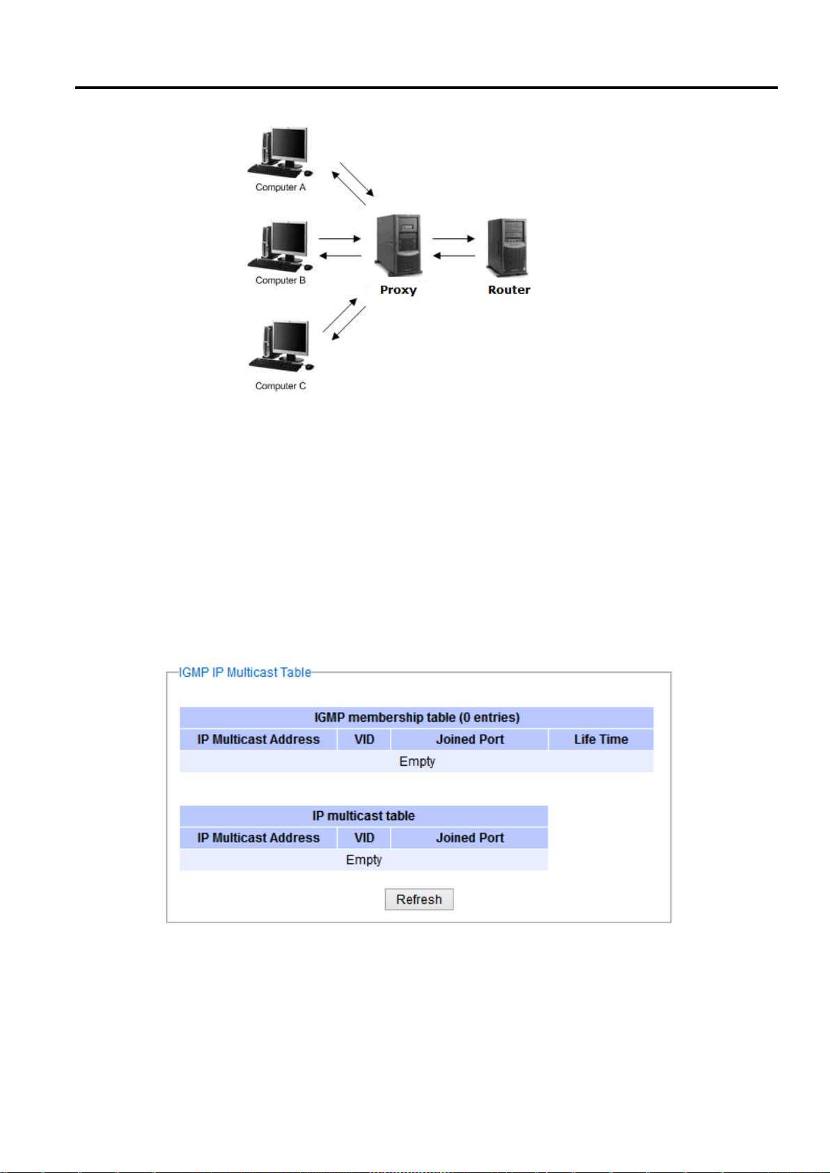
Industrial Managed
Ethernet Switch
User Manual
Configuring with a
Web Browser
Figure 2.84 Example of IGMP Proxy
IGMP Fast-leave: When a leave group message is received, the ports in the group will be immediately removed
from the IP multicast entry.
2.10.1.2 IGMP IP Multicast Table
This webpage provides information about IGMP membership table and IP multicast table. Figure 2.85 depicts the
IGMP’s IP Multicast Table webpage. The upper table is an IGMP membership table and the lower table is IP
multicast table which contain both static configured IP multicast addresses and dynamically joined IP multicast
addresses. The static configured port is manually added by the users, while the dynamically joined port is added by
the managed switch’s IGMP snooping feature. To get the latest update information on each table please click on
the Refresh button.
Figure 2.86 shows examples of IGMP membership table and IP multicast table. Note that the display format in
Figure 2.86 is from an early version of managed switch firmware which may have a slightly different display format
from Figure 2.85. These tables are based on the information in the memory of the managed switch. The IGMP
membership table contains IP Multicast Address, VLAN ID (VID), Joined Port (port number) and Life Time. Note
that the Life Time is in the unit of second. The IP multicast table has only IP Multicast Address, VLAN ID (VID), and
Page 77 of 190
Figure 2.85 IGMP's IP Multicast Table Webpage
Page 78
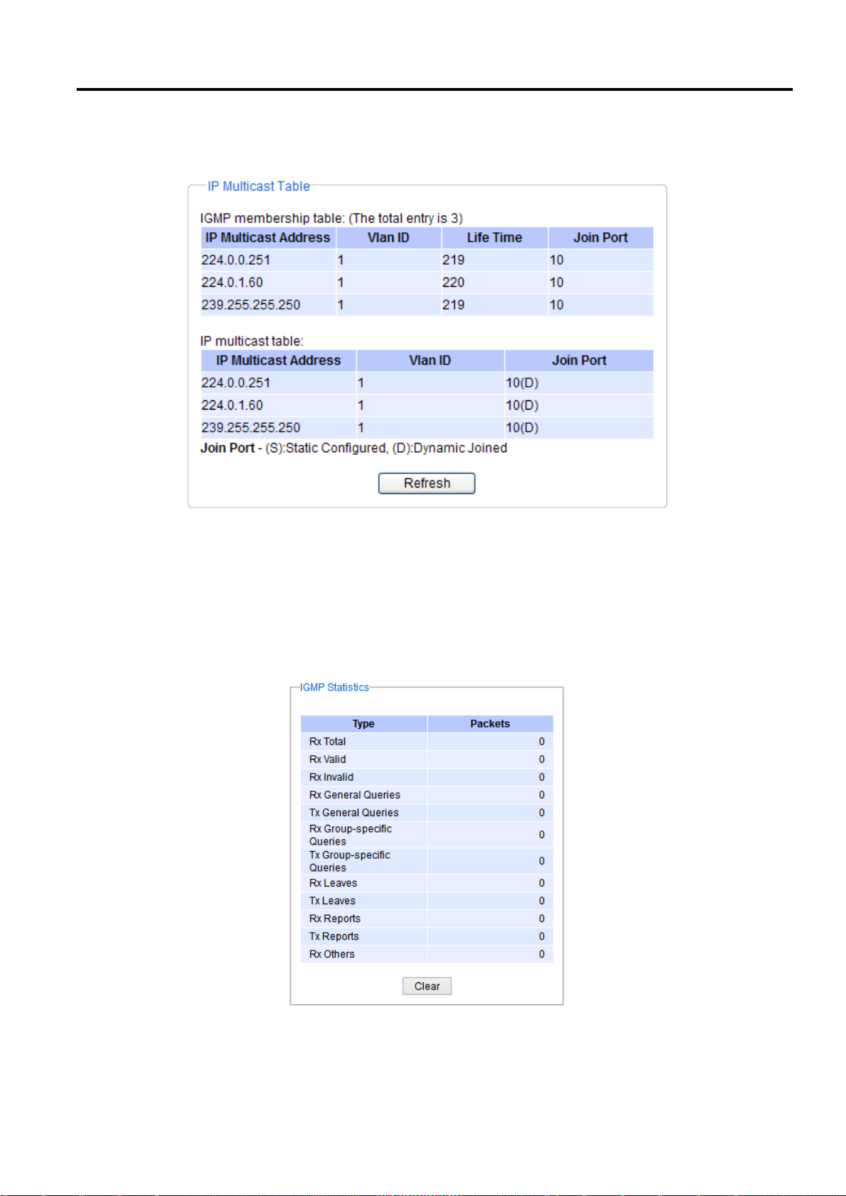
Industrial Managed
Ethernet Switch
User Manual
Configuring with a
Web Browser
Joined Port. Note that the joined port can be labelled with (S) or (D) which refer to as Static Configured or
Dynamically Joined, respectively.
Figure 2.86 Example of IGMP's IP Multicast Table
2.10.1.3 IGMP Statistics
This webpage provides information about IGMP statistics as shown in Figure 2.87. The users can view the number
of IGMP packets in different categories: Rx Total, Rx Valid, Rx Invalid, Rx General Queries, Tx General Queries, Rx
Group-Specific Queries, Tx Group-Specific Queries, Rx Leaves, Tx Leaves, Rx Reports, Tx Reports, and Rx Others.
The users can reset the numbers in all categories by clicking on the Clear button.
Example of IGMP statistics are shown in Figure 2.88. Note that the display format in Figure 2.88 is from an early
version of managed switch firmware which may have a slightly different display format from Figure 2.87. It shows
Page 78 of 190
Figure 2.87 IGMP Statistics Webpage
Page 79
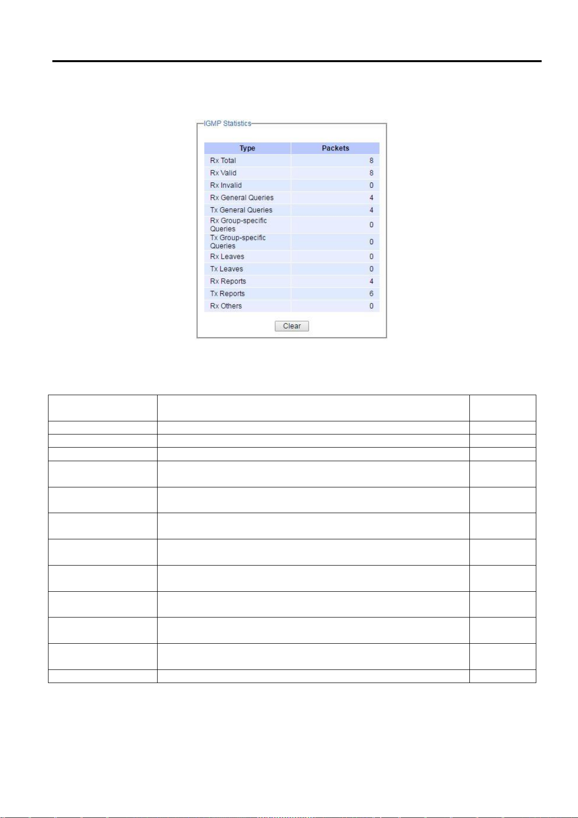
Industrial Managed
Ethernet Switch
User Manual
Configuring with a
Web Browser
Statistics Label
Description
Factory
Default
Rx Total
Total number of IGMP packets received by the managed switch
-
Rx Valid
Number of valid IGMP packets received by the managed switch
-
Rx Invalid
Number of invalid IGMP packets received by the managed switch
-
Rx General Queries
Number of IGMP’s Membership General Query packets received by
the managed switch
-
Tx General Queries
Number of IGMP’s Membership General Query packets transmitted by
the managed switch
-
Rx Group Specific
Queries
Number of IGMP’s Membership Group Specific Query packets
received by the managed switch
-
Tx Group Specific
Queries
Number of IGMP’s Membership Group Specific Query packets
transmitted by the managed switch
-
Rx Leaves
Number of IGMP’s Leave Group packets received by the managed
switch
-
Tx Leaves
Number of IGMP’s Leave Group packets transmitted by the managed
switch
-
Rx Reports
Number of IGMP’s Membership Report packets received by the
managed switch
-
Tx Reports
Number of IGMP’s Membership Report packets transmitted by the
managed switch
-
Rx Others
Number of IGMP’s other packets received by the managed switch
-
the statistical values of IGMP packets which the managed switch received and transmitted over time. Table 2.30
summarizes the descriptions of the IGMP statistics.
Figure 2.88 Example of IGMP's Statistics
Table 2.30 Descriptions of IGMP Statistics
Page 79 of 190
Page 80
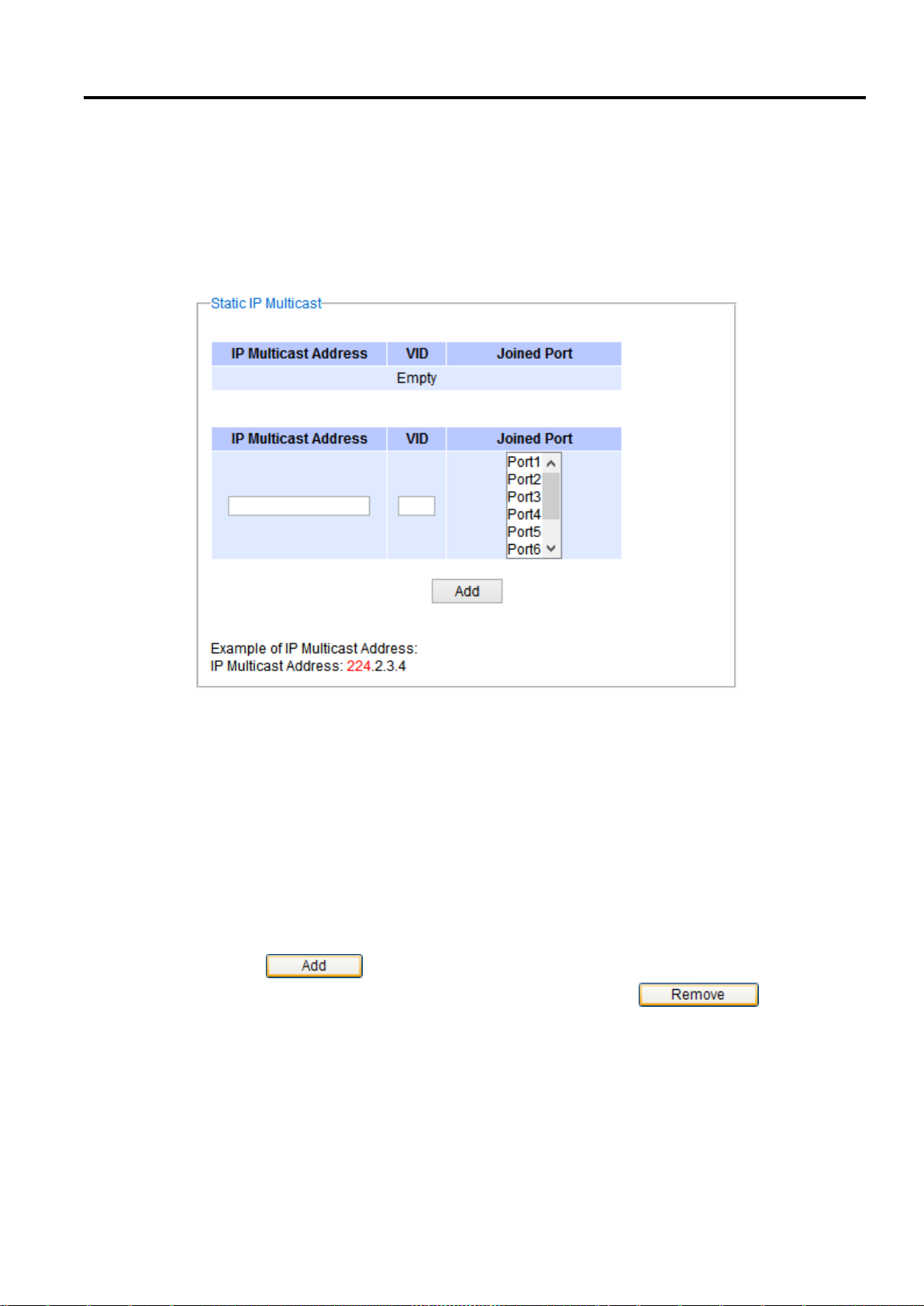
Industrial Managed
Ethernet Switch
User Manual
Configuring with a
Web Browser
2.10.2 Static IP Multicast
This subsection allows the users to manually add new or remove existing static IP multicast and the joined port(s).
Figure 2.89 shows the Static IP Multicast webpage where the upper part of the page is a table of existing IP
Multicast Address entries and the lower part of the page contains the fields for adding new IP Multicast Address
entry to the table. The users are required to supply the IP Multicast Address, VLAN ID (VID), and the lists of the port
numbers which will join the static IP multicasting group (joined port).
Figure 2.89 Static IP Multicast Setting Webpage
An example of an entry of IP multicast group is shown in Figure 2.90 where there is an existing IP Multicast
Address of 224.2.3.4 which belongs to VLAN 1 and has port number 2, 3, and 6 in the group. The following
procedures outline how to add a new IP multicast group. For example, an IP multicast group address is 224.1.1.1
and the joining ports are Port1, Port2 and Port5 with VLAN = 1.
First, the users should enter the IP = 224.1.1.1 in the IP Multicast Address column.
Then, the users should enter the VLAN ID = 1 in the VLAN ID (VID) column.
Then, while holding the “Ctrl” key on the keyboard, click on all corresponding port numbers under the Join
Port column (Port1, Port2, and Port5 in this example) to select which port(s) will join in the IP multicast
group.
Finally, click on the button. The IP address is then added as it shows on Figure 2.90.
To remove an existing static IP multicast address from the table, click the button of that
entry.
These procedures are similar to the procedures for adding or removing the Unicast/Multicast MAC address
explained in Section 2.8.1. The only difference is that the IP multicast address has the form of 224.XX.XX.XX.
Note that IPv4 multicast address (Class D) is in between 224.0.0.0 and 239.255.255.255.
Page 80 of 190
Page 81
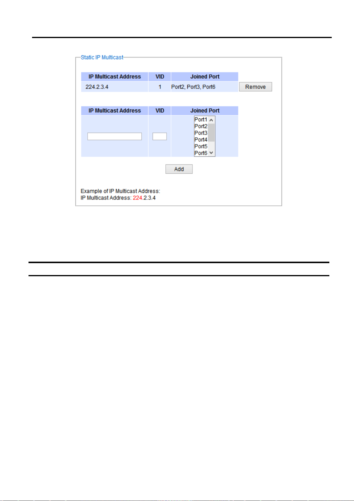
Industrial Managed
Ethernet Switch
User Manual
Configuring with a
Web Browser
Figure 2.90 Example of Static IP Multicast Setting
2.11 SNMP
Simple Network Management Protocol (SNMP) is a protocol for managing devices on IP networks. It exposes
management data in the form of variables on the managed systems which describe the system configuration.
These variables can then be queried or defined by the users. The SNMP is used by network management system
or third-party software to monitor devices such as managed switches in a network to retrieve network status
information and to configure network parameters. The Atop’s managed switch support SNMP and can be
configured in this section. The SNMP setting has four categories and its dropdown menu is shown in Figure 2.91,
which are:
SNMP Agent
SNMP V1/V2c Community Setting
Trap Setting
SNMP V3 Authentication (Auth.) Setting
Page 81 of 190
Page 82
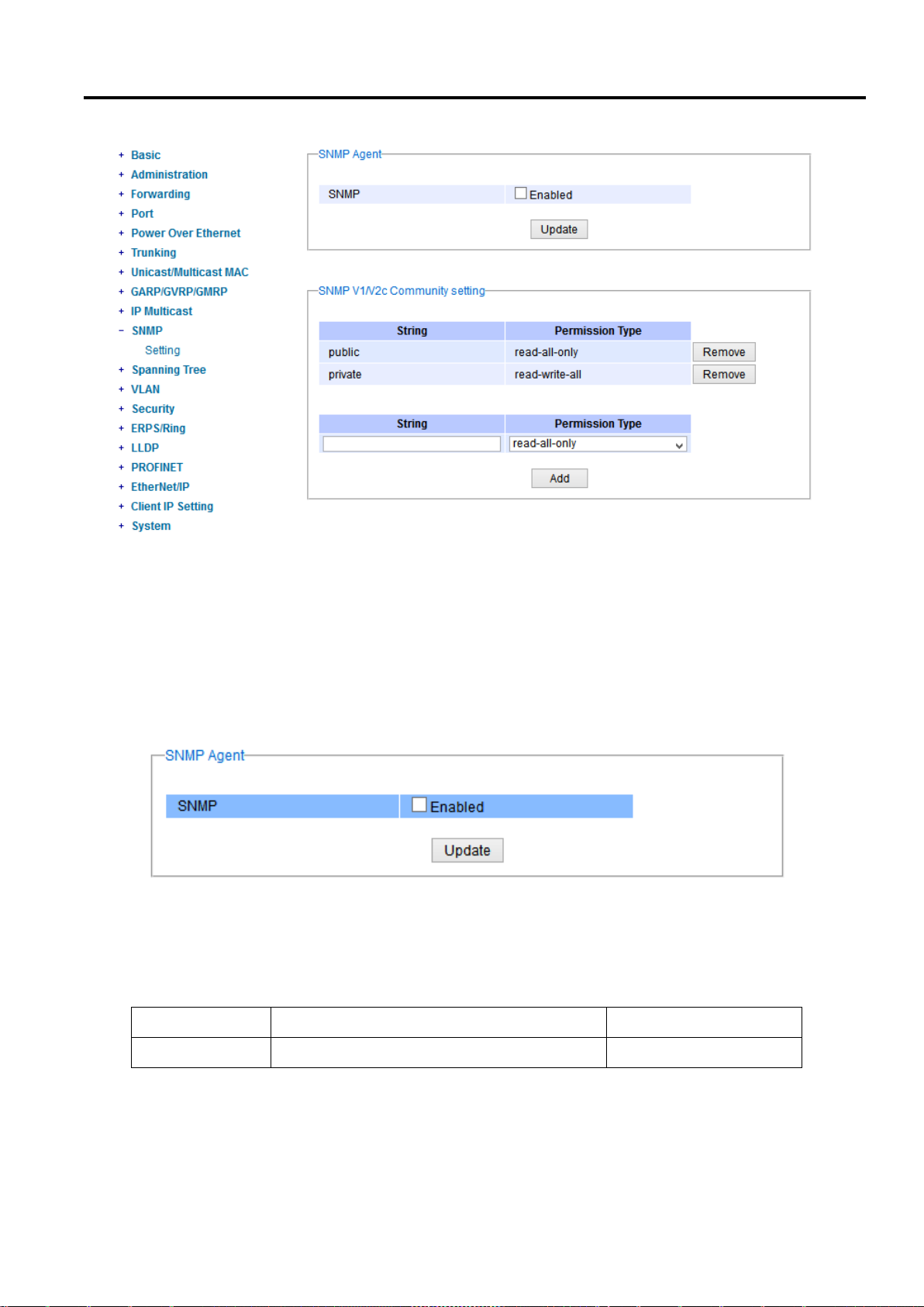
Industrial Managed
Ethernet Switch
User Manual
Configuring with a
Web Browser
Label
Description
Factory Default
SNMP
Check the box to enable SNMP V1/V2c/V3.
Disabled
Figure 2.91 SNMP Dropdown Menu
2.11.1 SNMP Agent
To enable SNMP agent on the managed switch, please check the Enabled box and click Update button as shown
in Figure 2.92. The SNMP version 1 (V1), version 2c (V2c) and version 3 are supported by Atop’s managed switches
as summarized in Table 2.31. Basically, SNMP V1 and SNMP V2c have simple community string based
authentication protocol for their security mechanism, while SNMP V3 is improved with cryptographic security.
Figure 2.92 SNMP Enabling Box
Table 2.31 Description of SNMP Setting
Page 82 of 190
Page 83
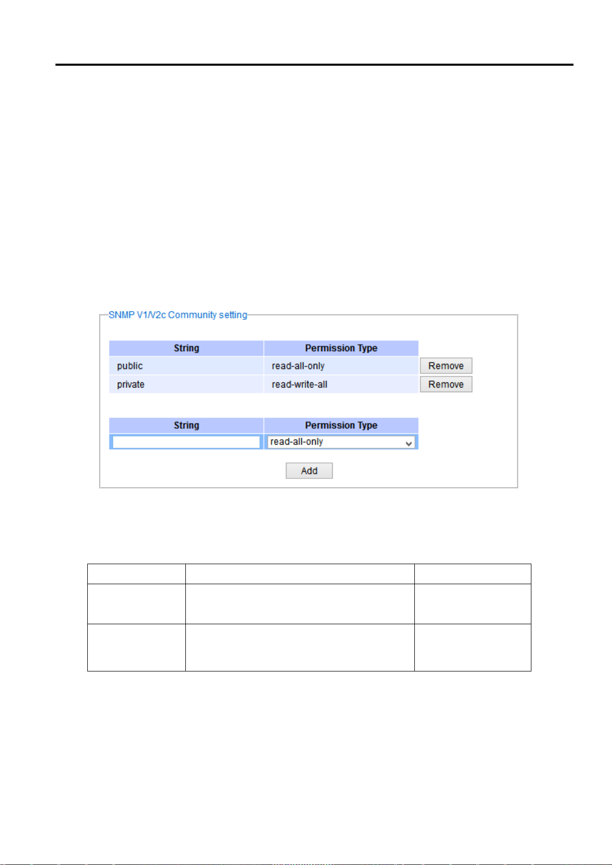
Industrial Managed
Ethernet Switch
User Manual
Configuring with a
Web Browser
Label
Description
Factory Default
(Community)
Strings
Define name of strings for authentication.
Max. 15 Characters.
Public (read-all-only)
Private (read-write-all)
Permission Type
Choose a type from the dropdown list: read-allonly and read-write-all. See notes below for a
briefed explanation.
-
2.11.2 SNMP V1/V2c Community Setting
The managed switch supports SNMP V1, V2c, and V3. SNMP V1 and SNMP V2c use a community string matching
for authentication. This authentication will allow network management software to access the information or data
objects defined by Management Information Bases (MIBs) on the managed switch. Note that this simple
authentication is considered a weak security mechanism. It is recommended to use SNMP V3, if possible. There
are two levels of authentications or permission type in EHG75XX series, which are read-all-only or read-write-all.
For example, in our default setting as shown in Figure 2.93, an SNMP agent, which is a network management
software module residing on the managed switch, can access all objects with read-all-only permissions using the
string public. Another setting example is that the string private has permission of read-write-all.
This community string option allows the users to set a community string for authentication or remove existing
community string from the list by clicking on the Remove button at the end of each community string item. The
users can specify the string names on the String field and the type of permissions from the dropdown list as shown
in Figure 2.93.
Table 2.32 briefly provides descriptions of SNMP’s community string setting.
Figure 2.93 SNMP Community Strings
Table 2.32 Descriptions of Community String Settings
*NOTE:
Read-all-only: permission to read OID 1 Sub Tree.
Read-write-all: permission to read/write OID 1 Sub Tree.
Page 83 of 190
Page 84
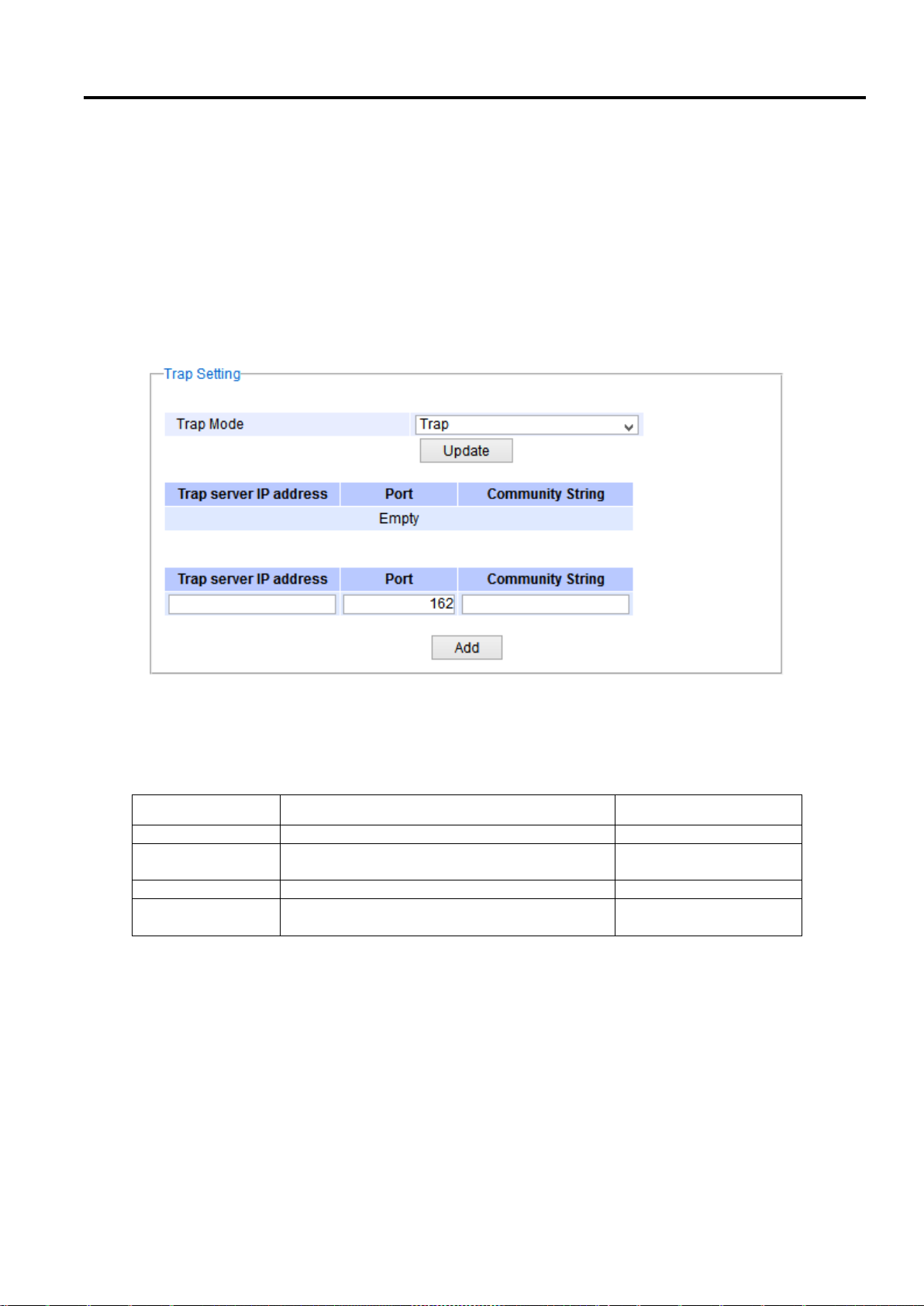
Industrial Managed
Ethernet Switch
User Manual
Configuring with a
Web Browser
Label
Description
Factory Default
Trap Mode
Choose between Trap and Inform
Trap
Trap server IP
address
Enter the IP address of your Trap Server.
NULL
Port
Enter the trap Server service port.
162
Community
String
Enter the community string for authentication.
Max. 15 characters.
NULL
2.11.3 Trap Setting
The managed switch provides a trap function that allows switch to send notification to agents with SNMP traps or
inform. The notifications are based on the status changes of the switch such as link up, link down, warm start, and
could start. For inform mode, after sending SNMP inform requests, switch will resends inform request if it does not
receive response within 10 seconds. The switch will try re-send three times. This option allows users to configure
SNMP Trap Setting by setting the destination IP Address of the Trap server, Port Number of the Trap server, and
Community String for authentication. Figure 2.94 shows these Tap Setting’s options. The first line enables the
users to select the Trap Mode which can be either Trap or Inform. Please click on the Update button after selecting
the desired Trap Mode. After entering all required fields for Trap Setting in the last line, please click on the Add
button. Table 2.33 summarizes the descriptions of trap receiver settings.
Figure 2.94 Example of Trap Receiver Setting
Table 2.33 Descriptions of Trap Receiver Settings
2.11.4 SNMPv3 Auth. Setting
As mentioned earlier, SNMP V3 is a more secure SNMP protocol. In this part, the users will be able to set a
password and an encryption key to enhance the data security. When choosing this option, the users can
configure SNMP V3’s authentication and encryption. MD5 (Message-Digest algorithm 5) is used for
authentication password and DES (Data Encryption Standard) is used for data encryption algorithm. Figure 2.95
shows the SNMP V3 Authentication Setting’ options. The users can view existing SNMP V3 users’ setting on the
upper table where it provides information about user name, authentication type, and data encryption. The users
have an option to remove existing SNMP V3 user by clicking on the Remove button in the last column of each
entry. To add a new SNMP V3 user, the users have to select the user Name from the dropdown list which can be
either Admin or User. Then, the authentication password with a maximum length of 31 characters has to be
Page 84 of 190
Page 85
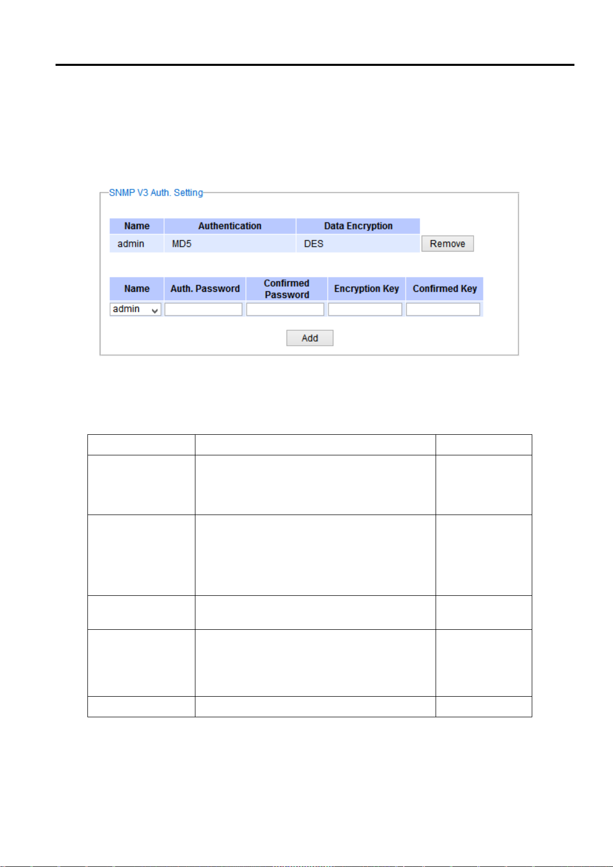
Industrial Managed
Ethernet Switch
User Manual
Configuring with a
Web Browser
Label
Description
Factory Default
Name
Choose from one of the following options:
Admin: Administration level.
User: Normal user level.
Admin
Auth.
(Authentication)
Password
Set an authentication password for the user name
specified above. If the field is left blank, there will
be no authentication. Note that the authentication
password is based on MD5.
Max. 31 characters.
NULL
Confirmed
Password
Re-type the Authentication Password to confirm.
NULL
Encryption Key
Set encryption key for more secure protection of
SNMP communication. Note that the encryption
algorithm is based on DES (.
Max. 31 characters.
NULL
Confirmed Key
Re-type the Encryption Key
NULL
entered in the Auth. Password field and re-entered again in the Confirmed Password field. Note that if no
password is provided, there will be no authentication for SNMP V3. Finally, the encryption key with a maximum
length of 31 characters can be entered in the Encryption Key and re-entered again in Confirmed Key field. After
filling all the required fields, please click on Add button to update the information on the managed switch. Table
2.34 lists the descriptions of SNMP V3 settings.
Figure 2.95 SNMPv3 Users' Options
Table 2.34 Descriptions of SNMP V3 Settings
Page 85 of 190
Page 86
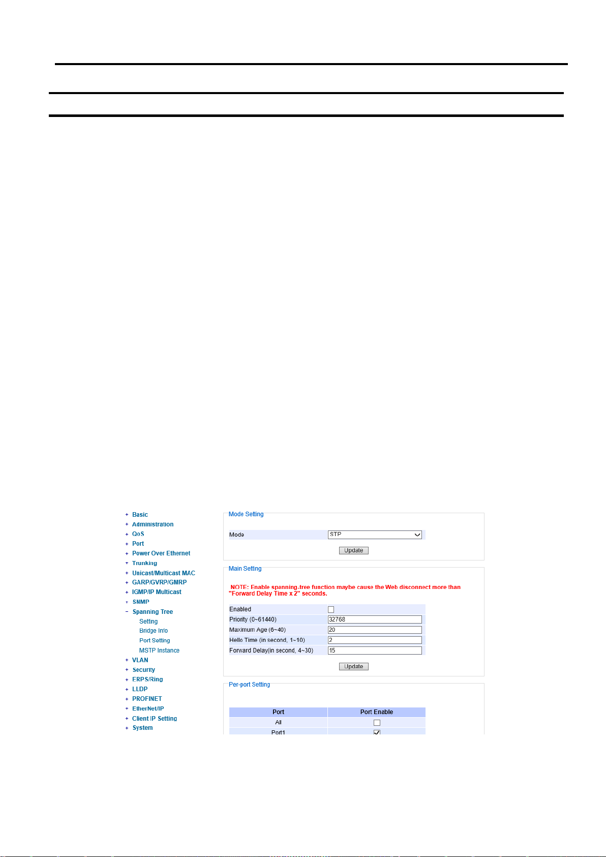
Industrial Managed
Ethernet Switch
User Manual
Configuring with a
Web Browser
2.12 Spanning Tree
IEEE 802.1D Standard spanning tree functionality is supported by Atop’s managed switches. The Spanning Tree
Protocol (STP) provides a function to prevent switching loops and broadcast radiation at the OSI layer 2. A
switching loop occurs in a network when there are multiple connections or redundant paths between two network
switches or at least two ports are connected on both sides of the two network switches. The switching loop can
create a broadcast radiation, which is the accumulation of broadcast and multicast traffics in a computer network.
As broadcast and multicast messages are forwarded by bridges/switches to every port, the bridges/switches will
repeatedly rebroadcast the broadcast messages, and this accumulation of traffic can flood the network. STP
creates a spanning tree topology and disables those links of the network that are not part of the spanning tree,
which leaves only a single active path between two nodes. This function can avoid flooding and increase network
efficiency. Therefore, Atop’s managed switches deploy spanning tree as a tool when the users set up connection
or port redundancy or fault-tolerance in their network.
RSTP (Rapid Spanning Tree Protocol), IEEE 802.1W, is also supported in Atop’s managed switches. It is an
evolution of the STP, but it is still backwards compatible with standard STP. RSTP has the advantage over the STP.
When there is a topology change such as link failure in the network, the RSTP will converge significantly faster to a
new spanning tree topology. RSTP improves convergence on point-to-point links by reducing the Max-Age time to
3 times Hello interval, removing the STP listening state, and exchanging a handshake between two switches to
quickly transition the port to forwarding state.
MSTP (Multiple Spanning Tree Protocol) is also a standard defined by the IEEE 802.1s that allows multiple VLANs
to be mapped to a single spanning tree instance called MST Instance, which will provide multiple pathways across
the network. It is compatible with STP and RSTP. To support lager network, MSTP groups bridges/switches into
regions that appear as a single bridge to other devices. Within each region, there can be multiple MST instances.
MSTP shares common parameters as RSTP such as port path costs. MSTP also help prevent switching loop and
has rapid convergence when there is a topology change. It is possible to have different forwarding paths for
different MST instances. This enables load balancing of network traffic across redundant links.
This section describes how to setup the spanning tree protocol (STP), rapid spanning tree protocol (RSTP), and
Multiple Spanning Tree Protocol (MSTP). Figure 2.96 depicts the dropdown menu for Spanning Tree.
Page 86 of 190
Figure 2.96 Spanning Tree Dropdown Menu
Page 87
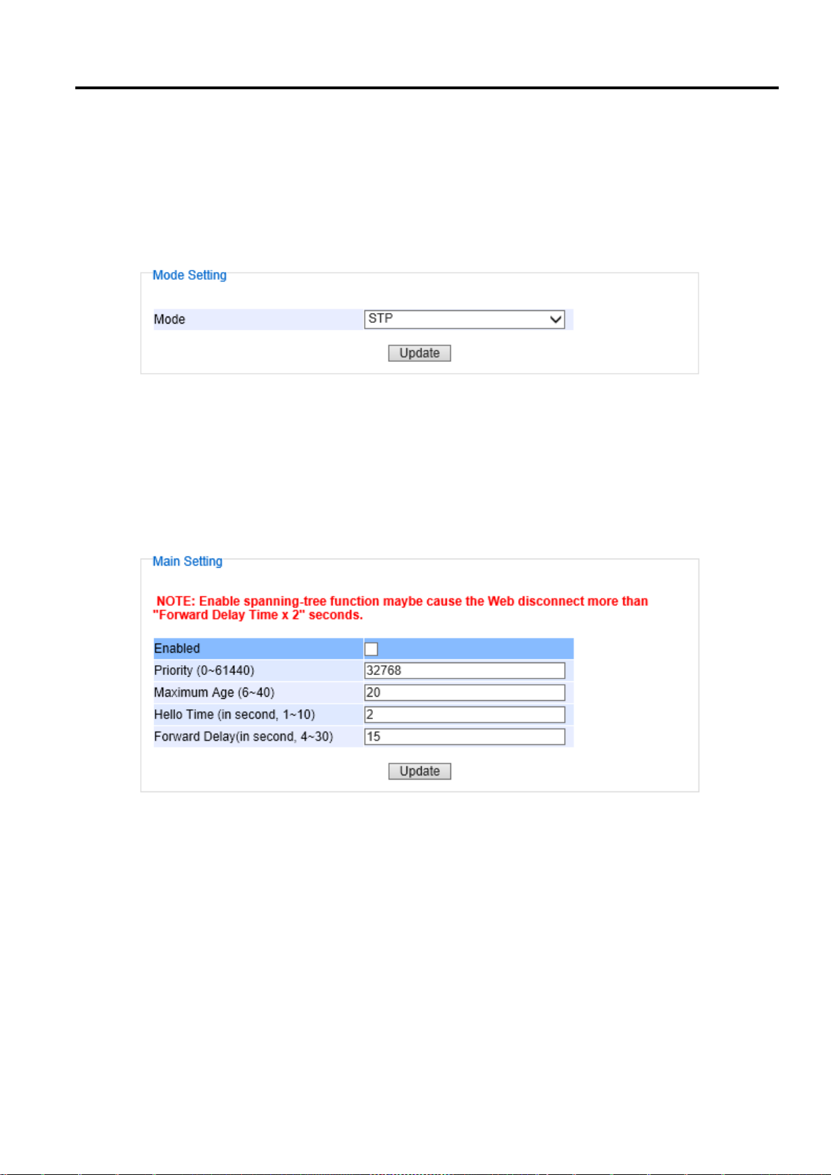
Industrial Managed
Ethernet Switch
User Manual
Configuring with a
Web Browser
2.12.1 Spanning Tree Setting
The users can select the spanning tree mode which are based on different spanning tree protocols in this webpage.
Figure 2.97 shows the mode setting for spanning tree. There are three spanning tree modes to choose from the
dropdown menu, which are spanning tree protocol (STP), rapid spanning tree protocol (RSTP), and multiple
spanning tree protocol (MSTP). After choosing the desired mode, please click Update button to allow the change
to take effect.
Figure 2.97 Spanning Tree Mode Setting
Under the mode setting, there is a box for Main Setting of spanning tree’s parameters as showed in Figure 2.98.
The users can enable or disable spanning tree protocol in the Main Setting by checking the box behind the Enabled
option. The users can fine tune the Priority, Maximum Age, Hello Time, and Forward Delay. After configuring the
spanning tree’s main parameters, please click Update button to allow the change to take effect. The description of
each parameter is listed in Table 2.35.
When the users change the spanning tree mode setting to MSTP and click the Update button in the Mode Setting
box Figure 2.97, the Main Setting box in Figure 2.98 will be changed to Figure 2.99. The user can notice that the
Priority field is disappeared while there are three more fields show up which are Max Hops, Revision Level, and
Page 87 of 190
Figure 2.98 Spanning Tree Main Setting for STP and RSTP
Page 88
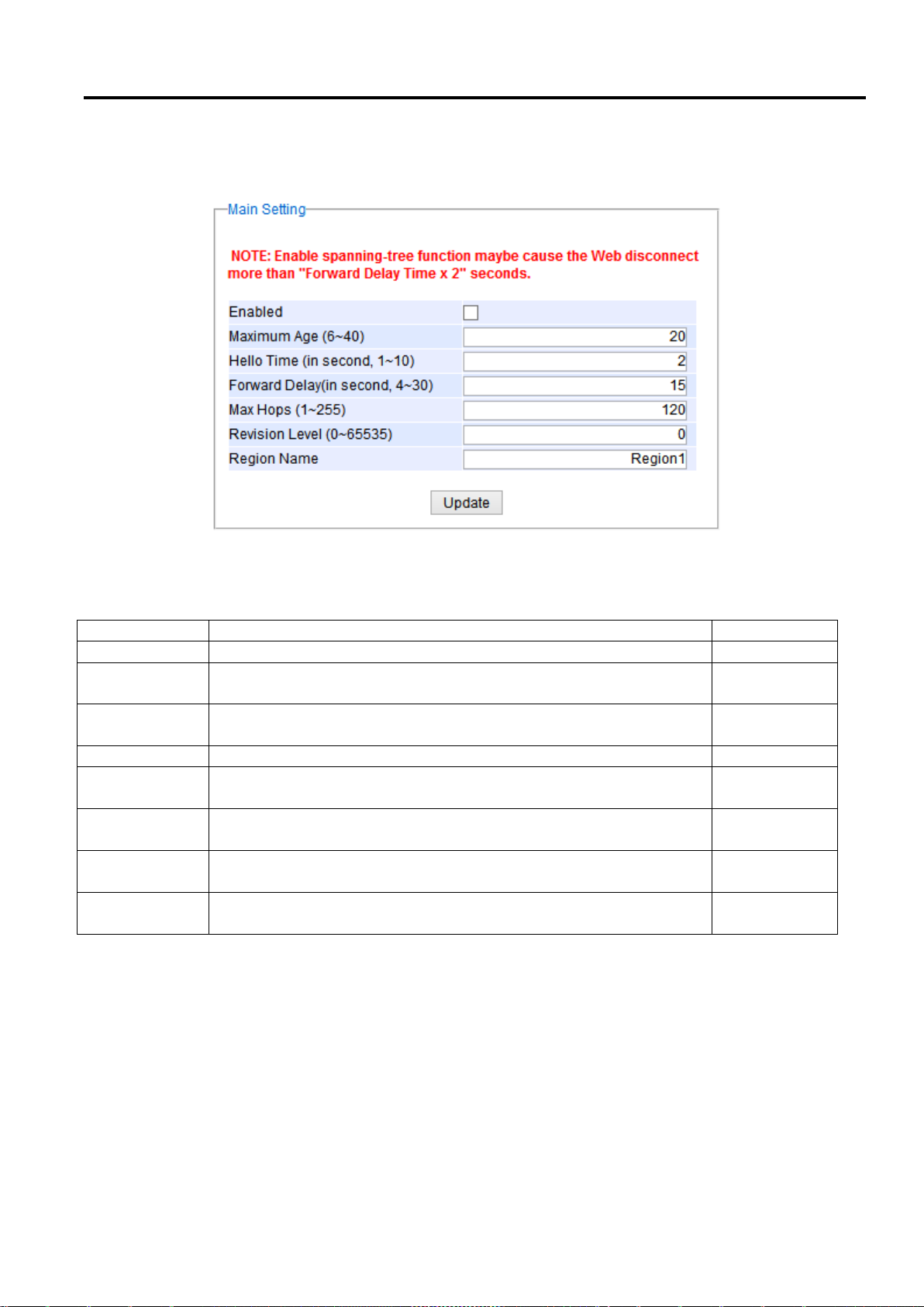
Industrial Managed
Ethernet Switch
User Manual
Configuring with a
Web Browser
Label
Description
Default Factory
Enabled
Check the box to enable spanning tree functionality.
Disable
Priority
Enter a number to set the device priority. The value is in between 0 and
61440. The lower number gives higher priority.
32768
Maximum Age
Maximum expected arrival time for a hello message. It should be
longer than Hello Time.
20
Hello Time
Hello time interval is given in seconds. The value is in between 1 to 10.
2
Forward Delay
Specify the time spent in the listening and learning states in seconds.
The value is in between 4 to 30.
15
Max Hops (Only
for MSTP)
The value is between 1 to 255.
120
Revision Level
(Only for MSTP)
The value is between 0 to 65535.
0
Region Name
(Only for MSTP)
Text string indicate the region name
Region1
Region Name. Additionally, there will be a note add to the Per-port Setting box that currently MSTP mode does not
support trunk port now.
Figure 2.99 Spanning Tree Main Setting for MSTP
Table 2.35 Descriptions of Spanning Tree Parameters
The bottom part of the Spanning Tree Setting is the Per-port setting as shown in Figure 2.100. The users can
enable spanning tree functionality individually on each port or on all port by checking on the box under the Port
Enable column. The default setting is checking on all port. After making any change on the per-port setting,
please click on the Update button to update the change on the managed switch.
Page 88 of 190
Page 89
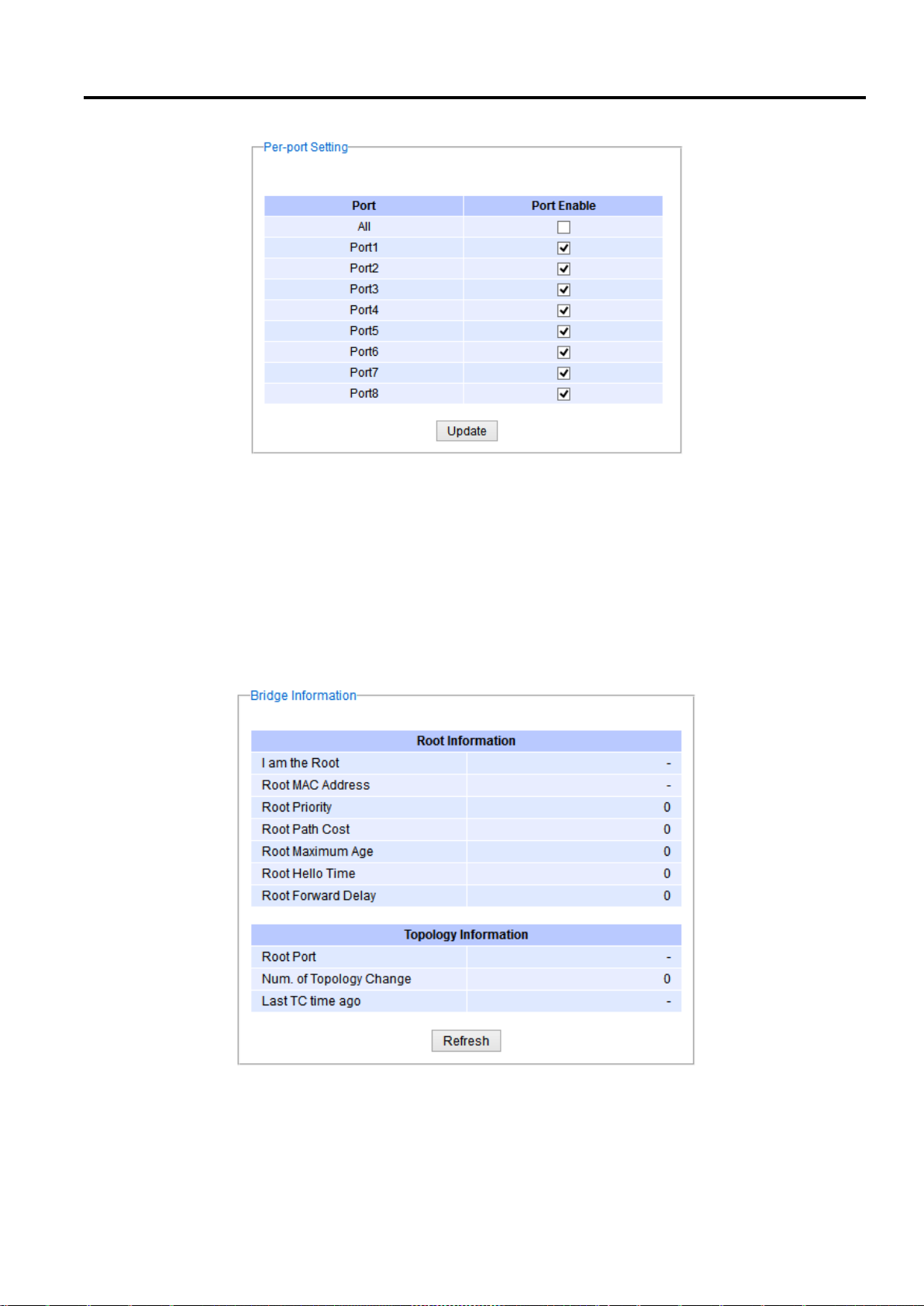
Industrial Managed
Ethernet Switch
User Manual
Configuring with a
Web Browser
2.12.2 Bridge Info
Figure 2.100 Spanning Tree Per-port Setting for STP and RSTP
Bridge Info (information) provides the statistical value of spanning tree protocol as shown in Figure 2.101. The
information is further divided into two parts: Root Information and Topology Information. To check the latest
information, please click on the Refresh button.
Table 2.36 and Table 2.37 summarize the descriptions of each entry in the root information table and topology
information table, respectively.
Page 89 of 190
Figure 2.101 Bridge Information Webpage
Page 90

Industrial Managed
Ethernet Switch
User Manual
Configuring with a
Web Browser
Label
Description
Factory Default
I am the Root
Indicator that this switch is elected as the root
switch of the spanning tree topology
-
Root MAC Address
MAC address of the root of the spanning tree
-
Root Priority
Root’s priority value: The switch with highest
priority has the lowest priority value and it will
be elected as the root of the spanning tree.
0
Root Path Cost
Root’s path cost is calculated from the data
rate of the switch’s port.
0
Root Maximum Age
Root’s maximum age is the maximum amount
of time that the switch will maintain protocol
information received on a link.
0
Root Hello Time
Root’s hello time which is the time interval for
RSTP to send out a hello message to the
neighboring nodes to detect any change in the
topology.
0
Root Forward Delay
Root’s forward delay is the duration that the
switch will be in learning and listening states
before a link begins forwarding.
0
Label
Description
Factory Default
Root Port
A forwarding port that is the best port from
non-root bridge/switch to root bridge/switch.
Note that for a root switch there is no root port.
-
Num. of Topology Change
The total number of spanning topology change
over time.
0
Last TC time ago
The duration of time since last spanning
topology change.
-
Table 2.36 Bridge Root Information
Table 2.37 Bridge Topology Information
2.12.3 Port Setting
Spanning Tree Port Setting shows the configured value of spanning tree protocol for each port, as shown in Figure
2.102. The configured information for each port is state, role, path cost, path priority, link type, edge, cost, and
designated information. To check the latest update on the statistics, please click on the Refresh button. Table 2.38
summarizes the descriptions of spanning three port setting. If Spanning Tree is enabled, the table below becomes
editable. Use the Update button to save the settings.
Page 90 of 190
Page 91
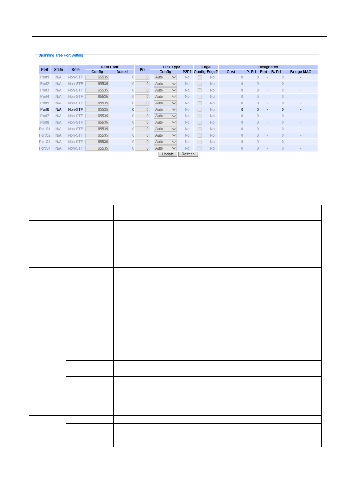
Industrial Managed
Ethernet Switch
User Manual
Configuring with a
Web Browser
Label
Description
Factory
Default
Port
The name of the switch port
-
State
State of the port:
‘Disc’: Discarding – No user data is sent over the port.
‘Lrn’: Learning – The port is not forwarding frames yet, but it is
populating its MAC Address Table.
‘Fwd’: Forwarding – The port is fully operational.
N/A
Role
Non-STP or STP
RSTP bridge port roles:
‘Root’ – A forwarding port that is the best port from non-root bridge
to root bridge.
‘Designated’ – A forwarding port for every LAN segment.
‘Alternate’ – An alternate path to the root bridge. This path is
different from using the root port.
‘Backup’ – A backup/redundant path to a segment whose another
bridge port already connects.
‘Disabled’ – Note strictly part of STP, a network administrator can
manually disable a port.
Non-
STP
Setting the path cost for each switch port
Path Cost
Config
Setting path cost (default: 0, meaning that using the system default
value (depending on link speed))
0
Actual
The actual value path cost (For STP and RSTP, please see Note 1
below and Table 2.39.)
0
Pri
Setting the port priority, used in the Port ID field of BPDU packet,
value = 16 × N, (N:0~15)
See Note 2 below.
128
The connection between two or more switches (for RSTP)
Link Type
Config
Setting of the Link Type
P2P: A port that operates in full-duplex mode is assumed to be
point-to-pint link.
Auto
Figure 2.102 Spanning Tree Port Setting Webpage
Table 2.38 Descriptions of Spanning Tree Port Setting
Page 91 of 190
Page 92

Industrial Managed
Ethernet Switch
User Manual
Configuring with a
Web Browser
Non-P2P: A half-duplex port (through a hub)
Auto: Detect link type automatically
P2P?
Yes: This port is a Point-to-Point (P2P).
No: This port is not Point-to-Point (Non-P2P).
No
Edge port is a port which no other STP/RSTP switch connect to (for
RSTP). An edge port can be set to forwarding state directly.
Edge
Config
Edge functional is set:
Yes or No
No
Edge?
Yes: This port is an edge port.
No: This port is not an edge port.
No
This shows some information of the best BPDU packet through this
port.
Designated
Cost
Root path cost
0
P. Pri. (Port
Priority)
Port priority (high 4 bits of the Port ID), Value = 16 × N, (N: 0~15)
128
Port
Interface number (lower 12 bits of the Port ID)
-
Bri. Pri. (Bridge
Priority)
Bridge priority, (value = 4096 × N, (N: 0~15)
32768
Bridge MAC
The MAC address of the switch which sent this BPDU
-
Data Rate
STP Cost (802.1D-1998)
RSTP Cost (802.1W-2004)
4 Mbits/s
250
5,000,000
10 Mbits/s
100
2,000,000
16 Mbits/s
62
1,250,000
100 Mbits/s
19
200,000
1 Gbits/s
4
20,000
2 Gbits/s
3
10,000
10 Gbits/s
2
2,000
Note:
1. In general, the path cost is dependent on the link speed. Table 2.39 lists the default values of path cost for STP
and RSTP.
Table 2.39 Default Path Cost for STP and RSTP
2. The sequence of events to determine the best received BPDU (which is the best path to the root).
Lowest root bridge ID determines the root bridge.
Lowest cost to the root bridge favors the upstream switch with the least cost to root.
Lowest sender bridge ID serves as a tie breaker if multiple upstream switches have equal cost to root.
Lowest sender port ID serves as a tie breaker if a switch has multiple (non-Ether channel) links to a single
upstream switch.
Bridge ID = priority (4 bits) + locally assigned system ID extension (12 bits) + ID [MAC Address] 48 bits
The default bridge priority is 32768.
Port ID = priority (4 bits) + ID (Interface number) (12 bits)
The default port priority is 128.
Page 92 of 190
Page 93
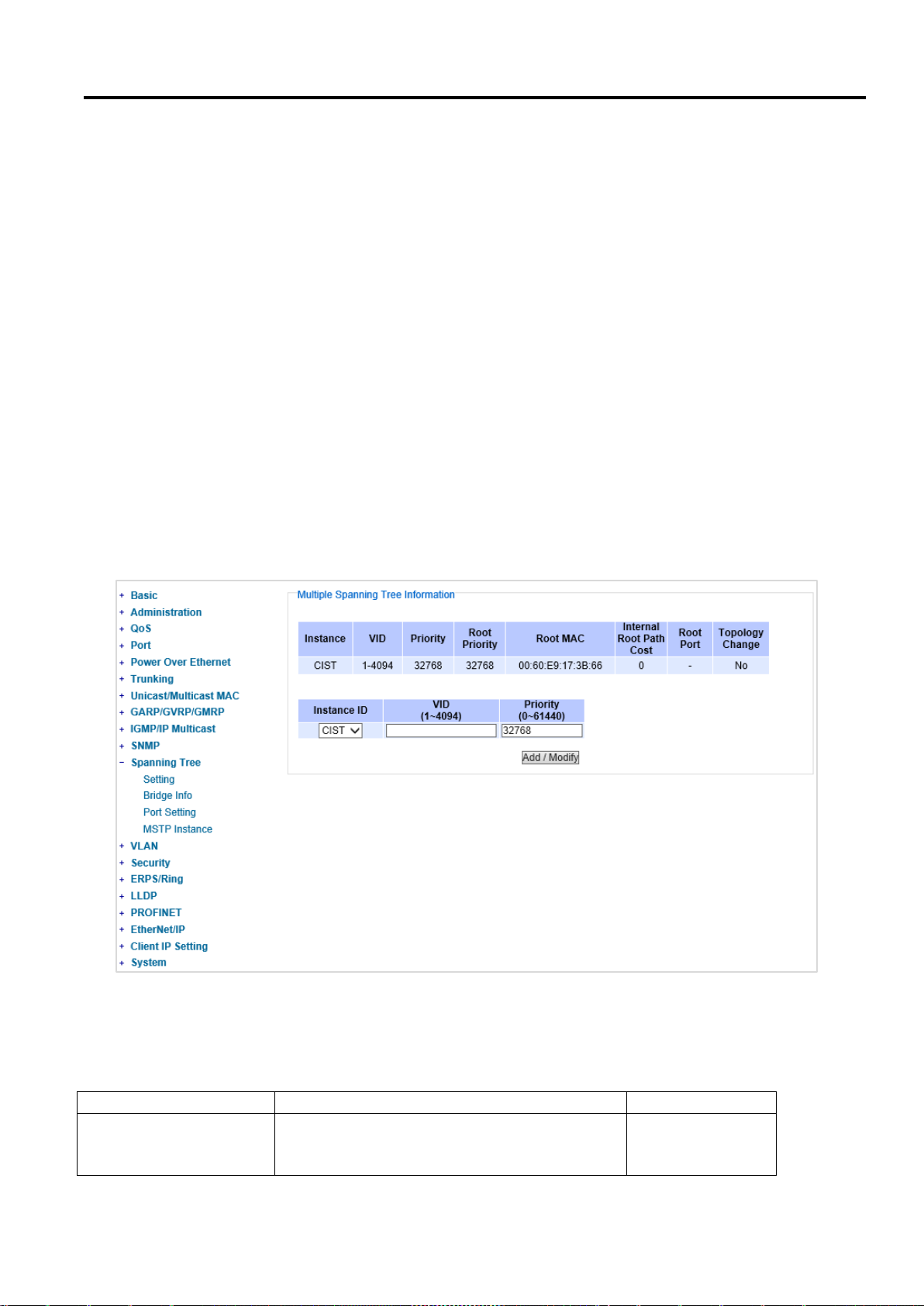
Industrial Managed
Ethernet Switch
User Manual
Configuring with a
Web Browser
Label
Description
Factory Default
Instance ID
Choose from dropdown list of
CIST (Common and Internal Spanning Tree)
or choose value from 1 to 63
CIST
2.12.4 MSTP Instance
MSTP enables the grouping and mapping of VLANs to different spanning tree instances. Therefore, an MST
Instance (MSTI) is a particular set of VLANs that are all using the same spanning tree. Note that MSTI is identified
by MSTI number and locally significant within MST region. Figure 2.103 illustrates the MSTP Instance webpage. In
this section, the uses can add or remove MSTP instance. The upper part of the webpage is a table of existing MSTP
instance in the managed switch. The users can add a new MSTP instance by choosing an Instance ID from the
dropdown list, enter the VLAN Identification number in the VID field, and set the desired priority in the Priority field.
After filling all information, please click the Add/Modify button to update the MSTP instance. The procedure for
setting up an MSTP instance is as follows:
Enable MSTP protocol in Section 2.12.1
Modify spanning tree main setting as described in Section 2.12.1
Select ports that you want to enable MSTP function in Section 2.12.1.
Add a Multiple Spanning Tree Instance (MSTI) in MSTP Instance webpage (this section).
o Choose an Instance Identification
o Add VLAN Identification numbers (VIDs) that will be member(s) of MSTP instance.
o Set Priority value of the switch.
o Click Add/Modify button.
Table 2.40 summarizes the descriptions of MSTP Information.
Page 93 of 190
Figure 2.103 MSTP Instance Webpage
Table 2.40 Description of MSTP Information
Page 94
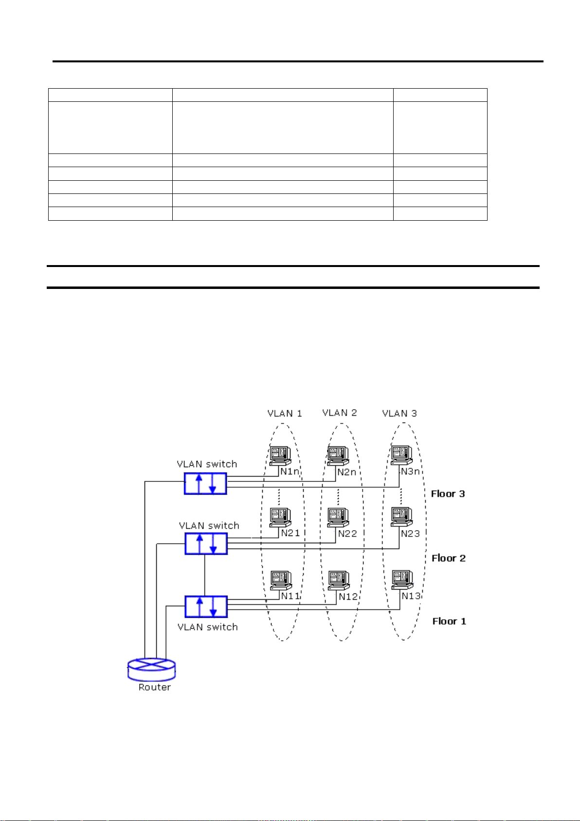
Industrial Managed
Ethernet Switch
User Manual
Configuring with a
Web Browser
VID
Enter a value for VLAN ID between 1 to 4094
-
Priority
Enter a value for priority value for the managed
switch between 0 – 61440. The lower value
means the higher priority. If the priority value is
0, the switch will be the Root Bridge in this MSTI.
32768
Root Priority
Display root priority value
32768
Root MAC
Display MAC address of the Root Bridge
-
Internal Root Path Cost
Display internal root path cost
0
Root Port
Display root port
-
Topology Change
Display Yes or No
No
2.13 VLAN
A Virtual Local Area Network (VLAN) is a group of devices that can be located anywhere on a network, but all
devices in the group are logically connected together. In other words, VLAN allows end stations to be grouped
together even if they are not located on the same network switch. With a traditional network, users usually spend
a lot of time on devices relocations, but a VLAN reconfiguration can be performed entirely through software. Also,
VLAN provides extra security because devices within a VLAN group can only communicate with other devices in
the same group. For the same reason, VLAN can help to control network traffic. Traditional network broadcasts
data to all devices, no matter whether they need it or not. By allowing a member to receive data only from other
members in the same VLAN group, VLAN avoids broadcasting and increases traffic efficiency (see Figure 2.104).
Figure 2.104 Example of VLAN Configuration
Atop’s managed switch EHG75XX series provide six approaches to create VLAN as follows:
Page 94 of 190
Page 95
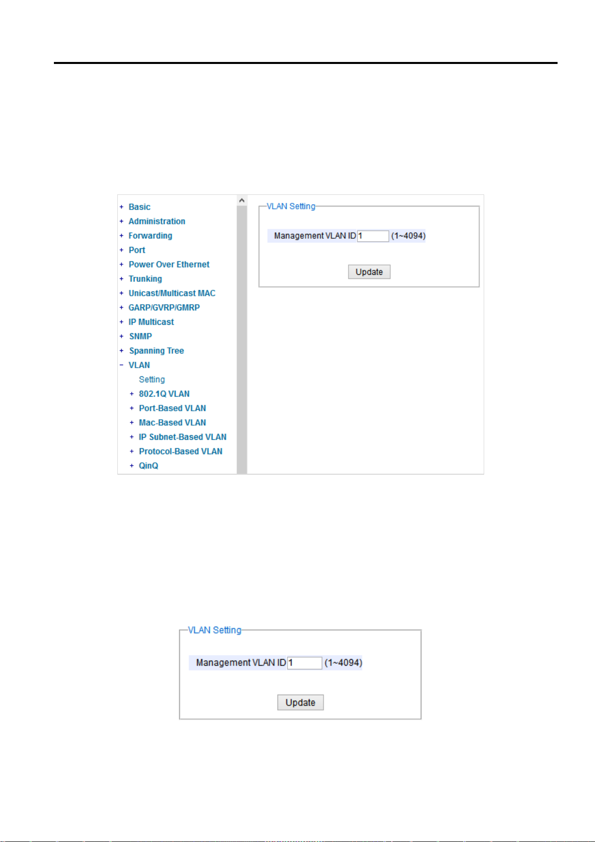
Industrial Managed
Ethernet Switch
User Manual
Configuring with a
Web Browser
Tagging-based (802.1Q) VLAN
Port-based VLAN
MAC-based VLAN
IP Subnet-Based VLAN
Protocol-Based VLAN
QinQ or Double Tagging-based VLAN
Figure 2.105 shows the drop-down menu under the VLAN section.
Figure 2.105 VLAN Dropdown Menu
2.13.1 VLAN Setting
The first menu under the VLAN section is the VLAN Setting. Here the management VLAN Identification number (ID)
is configured based on the IEEE 802.1Q standard. The default value is VID = 1. Note that the ID can be the number
from 1 to 4096. If the users change the management VLAN ID to other number, please click the Update button to
set it on the managed switch. Figure 2.106 depicts the VLAN Setting webpage. Table 2.41 describes the VLAN
Setting option.
Figure 2.106 VLAN Setting Webpage
Page 95 of 190
Page 96

Industrial Managed
Ethernet Switch
User Manual
Configuring with a
Web Browser
Label
Description
Factory Default
Management VLAN ID
Configure the management VLAN ID that can be
accessed this switch.Range from 1 to 4095.
1
Table 2.41 Description of VLAN Setting
2.13.2 802.1Q VLAN
Tagging-based (802.1Q) VLAN is the networking standard that supports virtual LAN (VLANs) on an Ethernet
network. The standard defines a system of VLAN tagging for Ethernet frames and the accompanying procedures
for bridges and switches in handling such frames. The standard also contains provisions for a quality of service
prioritization scheme commonly known as IEEE 802.1Q.
VLAN tagging frames are frames with 802.1Q (VLAN) tags that specify a valid VLAN identifier (VID). Whereas,
untagged frames are frames without tags or frames that carry 802.1p (prioritization) tags and only having
prioritization information and a VID of 0. When a switch receives a tagged frame, it extracts the VID and forwards
the frame to other ports in the same VLAN.
For a 802.1Q VLAN packet, it adds a tag (32-bit field) to the original packet. The tag is between the source MAC
address and the EtherType/length fields of the original frame. For the tag, the first 16 bits is the Tag protocol
identifier (TPID) field which set to a value of 0x8100 in order to identify the frame as an IEEE 802.1Q-tagged frame.
This field is located at the same position as the EtherType/length field in untagged frames, and is thus used to
distinguish the frame from untagged frames. The next 3 bits is the Tag control information (TCI) field which refers
to the IEEE 802.1p class of service and maps to the frame priority level. The next one bit is the Drop Eligible Indicator
(DEI) field which may be used separately or in conjunction with PCP to indicate frames eligible to be dropped in the
presence of congestion. The last 12 bits is the VLAN identifier (VID) field specifying the VLAN to which the frame
belongs.
Under the 802.1Q VLAN menu, there are three submenus which are Setting, PVID Setting, and VLAN Table as
shown in Figure 2.107.
Figure 2.107 802.1Q VLAN Dropdown Menu
2.13.2.1 802.1Q VLAN Settings
Figure 2.108 shows the 802.1Q VLAN Setting webpage which allow the users to add new tagged-based VLAN to
the managed switch. Please follow the following procedure to setting up the 802.1Q VLAN on the switch.
1. Go to 802.1Q VLAN, then select Setting submenu.
Page 96 of 190
Page 97
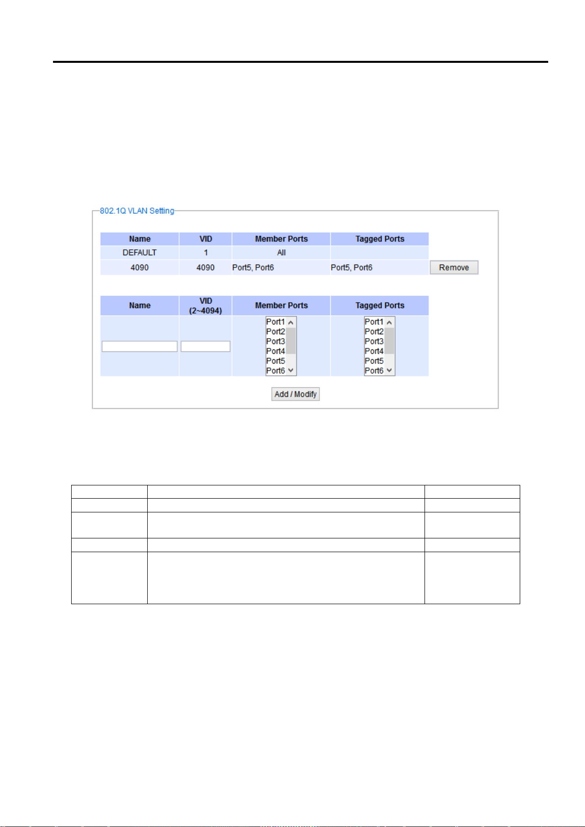
Industrial Managed
Ethernet Switch
User Manual
Configuring with a
Web Browser
Label
Description
Factory Default
Name
The VLAN ID name that can be assigned by the user.
Factory Default
VID
Configure the VLAN ID that will be added in static VLAN table
in the switch. The VLAN ID is in the range 2~4094.
Dependent
Member Ports
Configure the port to this specific VID.
All Ports
Tagged Ports
Configure the port that outgoing packet is tagged or
untagged.
Selected: The outgoing packet is tagged from this port.
Unselected: The outgoing packet is untagged from this port.
Dependent
2. Fill in appropriate Name, VID, Member Ports, and Tagged Ports as show in Figure 2.108. The description of
each fields is summarized in Table 2.42. Then, click Add/Modify button. Note to select multiple Member
Ports or multiple Tagged Ports, press and hold the Ctrl key while selecting multiple ports.
3. Go to 802.1Q VLAN’s PVID Setting described in the next subsection.
4. Choose the same ports, and enter PVID (which is the same as VID), see Figure 2.109.
To remove any of the VLAN from the 802.1Q VLAN setting, click the Remove button at the end of that particular
VLAN record as shown in Figure 2.108.
Figure 2.108 802.1Q VLAN’s Setting Webpage
Table 2.42 Setting Descriptions of 802.1Q VLAN Settings
*NOTE: Default settings only have VLAN ID on 1. To set VLAN ID to other value beside 1, users will have to assign
ports to be in that VLAN group.
2.13.2.2 802.1Q VLAN PVID Settings
Each port is assigned a native VLAN number called the Port VLAN ID (PVID). When an untagged frame goes through
a port, the frame is assigned to the port’s PVID. That is the frame will be tagged with the configured VLAN ID defined
in this subsection. Figure 2.109 shows the PVID Setting for 802.1Q VLAN where the upper table lists the current
PVID assigned to each port. The users can configure the PVID by select either on or multiple ports (by clicking and
Page 97 of 190
Page 98
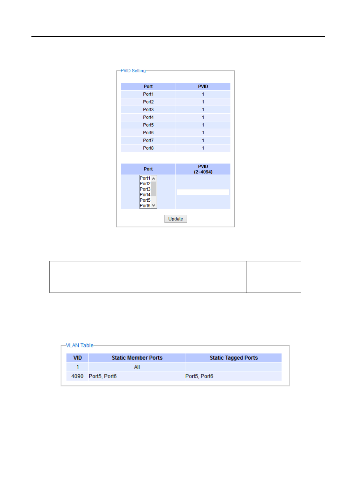
Industrial Managed
Ethernet Switch
User Manual
Configuring with a
Web Browser
Label
Description
Factory Default
Port
Select specific port(s) to set the PVID value
-
PVID
Configure the default 802.1Q VID tag assigned to specific Port.
The VLAN ID is in the range 1~4094.
1
holding the Ctrl key) and enter the desired PVID value between 2 to 4094. Please click Update button to allow the
configuration to take effect on the switch. Table 2.43 summarizes the PVID Setting’s descriptions.
Figure 2.109 802.1Q VLAN PVID Setting Webpage
Table 2.43 Setting Descriptions of 802.1Q VLAN PVID
2.13.2.3 802.1Q VLAN Table
This webpage shown in Figure 2.110 displays the 802.1Q VLAN table which lists all the VLANs that are
automatically and manually added/modified to the managed switch. Figure 2.111 illustrates examples of the static
and dynamic VLAN information of each VID. Table 2.44 summarizes the descriptions of VLAN Table.
Figure 2.110 802.1Q VLAN Table Webpage
Page 98 of 190
Page 99

Industrial Managed
Ethernet Switch
User Manual
Configuring with a
Web Browser
Label
Description
Factory
Default
VID
Indicate the VLAN ID number
Dependent
Static Member Ports
Indicate the member ports to this VID.
This entry is created by user.
All ports
Static Tagged Ports
Indicate the ports that outgoing packet is tagged or untagged.
Displayed: The outgoing packet is tagged from this port.
Non-displayed: The outgoing packet is untagged from this
port.
This entry is created by user.
Dependent
Dynamic Member Ports
Indicate the member ports to this VID.
This entry is created by GVRP (discussed in Section 2.9.3).
Dependent
Dynamic Tagged Ports
Indicate the member ports that outgoing packet is tagged or
untagged.
Displayed: The outgoing packet is tagged from this port.
Non-displayed: The outgoing packet is untagged from this
port.
This entry is created by GVRP (discussed in Section 2.9.3).
Dependent
Figure 2.111 Example of 802.1Q VLAN Table
Table 2.44 Descriptions of 802.1Q VLAN Table
2.13.3 Port-Based VLAN
Port-Based VLAN (or Static VLAN equivalent) assignments are created by assigning ports to a VLAN. If a device is
connected to a certain port, the device will be assigned a VLAN to that specific port. If a user changes the connected
port, a new port-VLAN assignment must be reconfigured for this new connection. To setup port-based VLAN,
please follow the following steps:
1. Click on Port-Based VLAN setting page as shown in Figure 2.112.
2. Select specific ports to be included in certain group by checking the corresponding box under the Member ports
on particular row of port-based VLANs’ Group ID. Note that if the users check the box under the Group ID
column, all of the Member Ports will belong to that VLAN’s Group ID.
3. Click on the Update button to allow the setting to take effect on the managed switch.
Page 99 of 190
Page 100
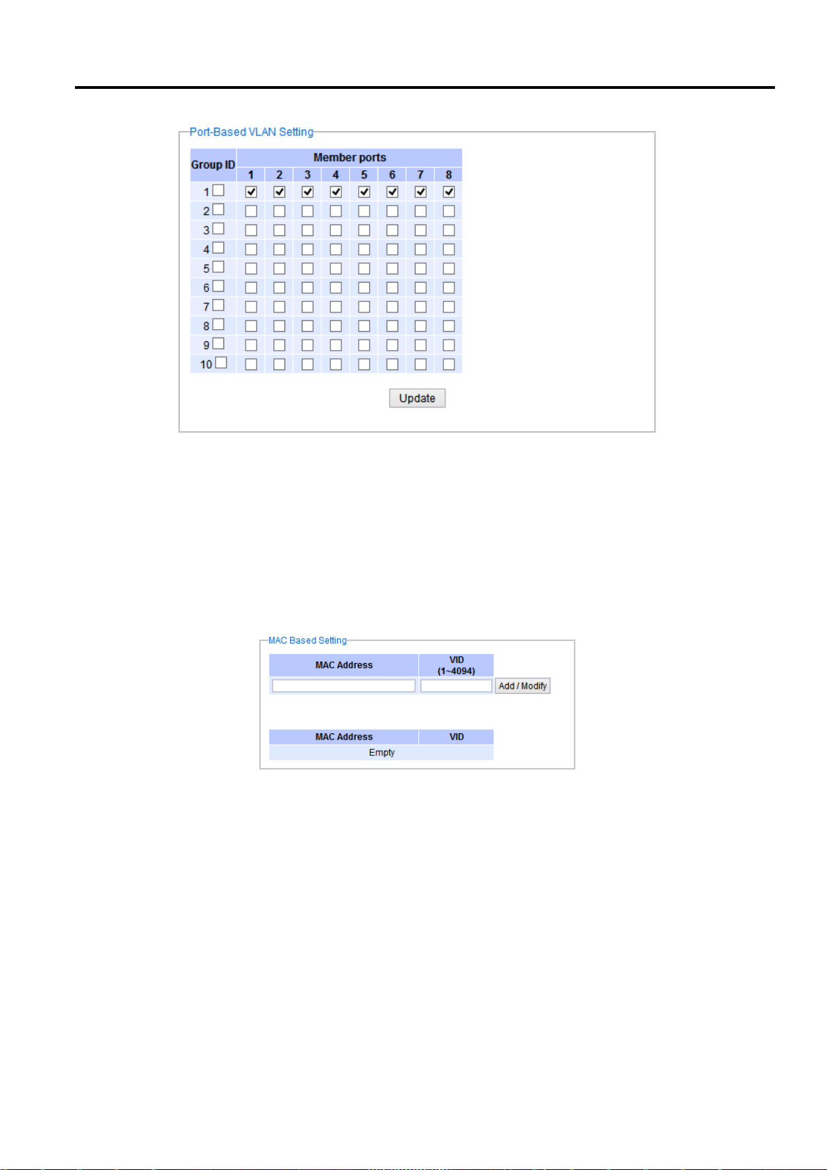
Industrial Managed
Ethernet Switch
User Manual
Configuring with a
Web Browser
2.13.4 MAC-Based VLAN
Figure 2.112 Port-based VLAN Setting Webpage
The managed switch also supports the ability to assign a VLAN ID (VID) to an untagged packet based on the source
MAC address. This can be set in this sub-menu as shown in Figure 2.113. There are maximum 512 entries in the
MAC-based VLAN table (Source MAC address + VLAN ID) in the lower part of this webpage. If the users enter a
duplicated MAC address into the MAC-based VLAN table, the old VLAN ID will be overwritten by the new VLAN ID.
The VLAN ID range is between 1 to 4096. If the source MAC address of a packet is matched with any entry inside
the MAC-based VLAN table here, the mapped VLAN ID will be added to the packet.
Figure 2.113 MAC-Based VLAN Setting Webpage
2.13.5 IP Subnet-Based VLAN
This sub-menu allows the user to assign a VLAN ID to an untagged packet based on the source IP address and the
prefix length which is called IP subnet-based VLAN. Figure 2.114 shows the webpage where the users can enter
the IP address, prefix length and VLAN ID (VID) for creating a VLAN based on its IP subnet. The list of existing IP
subnet-based VLAN is shown in the lower part of the webpage. This feature support maximum of 64 sets (IP
address + Prefix length + VLAN ID). The VLAN ID (VID) range is between 1 to 4096. This VLAN setup feature
supports both IPv4 and IPv6. If a duplicated pair of IP address and prefix length is entered into the table, there will
be an error message. The prefix length of IPv4 is 0 to 32 while the prefix length of IPv6 is 0 to 64.
Page 100 of 190
 Loading...