

Page 1

Page 2

SAFETY PRECAUTIONS
SAFETY PRECAUTIONS
SPECIFICATIONS
2
C1 Electric Catamaran
Length: 53.5in/1360mm
Overall Length: 58in/1470mm
Beam: 15in/380mm
Height: 9in/230mm
Overall Height: 13in/330mm
Weight: 13lbs (with battery)
Recommended Battery: 22.2V 25C
5000mAh LiPO
Run Time: 8-10 minutes
(22.2V 5000mAh LiPO)
Radio Equipment
Transmitter: Atomik 3Ch 2.4Ghz
Dimensions: 230 x 175 x 75mm
Weight: 1.4 lbs/566 oz (with battery)
Receiver: 8188 4-Channel Micro Receiver
Servo: 1825 High Torque Metal Gear
Speed: .17sec/60º
Torque: 107 oz/in (7.0kg.cm) @ 6V
Note! Product specifications are subject to change.
• Never swim out to retrieve an R/C boat that has stalled in the water. If you are going into the water, use
a small boat or kayak to retrieve your model. Always wear a PFD (Personal Flotation Device).
• Never stand in the water when operating your model boat.
• Remain clear of the propellers when the boat is running. Pay extra close attention to loose clothing,
jewelry, long hair and anything that can be caught in the spinning prop. CAUTION: A spinning
propeller can cause severe injury.
• The propeller and other running hardware are very sharp. Use extreme caution when working on or
around these parts.
• Your model is operated by radio signals sent by the transmitter. This system is susceptible to interference
from other radio signal sources. Before using your model, make sure that there is no other interference in the area.
• Never operate your model near swimmers or wildlife. The size and speed of this model can cause severe
injury and damage if a collision occurs.
• Some of the electronic components may become very hot during use and can severely burn you if
touched before they cool. Let the model stand and cool down before handling the motor, ESC and cooling
components.
• The battery used in this model can be dangerous. If the battery gets hot during charging, discontinue charging
immediately and disconnect battery from charger. Never leave the battery unattended while charging. If you are
unsure of how to charge this battery, please contact Atomik™ or seek the advice of your local hobby shop.
Never let children charge batteries without adult supervision.
• Charging and discharging batteries has the potential for serious injury to persons and damage to property. In
purchasing this product, the user agrees to accept responsibility for all such risks, and will not hold Atomik™, it’s
affiliates, manufacturers, distributors, or retail partners responsible for any accident, injury to persons, or
damage to property resulting from the use of this product.
• This product contains chemicals known to the State of California to cause cancer, birth defects and other
reproductive harm. Be responsible, dispose of properly.
• Always check your model for loose screws and components before operating.
• Always stop the engine before removing debris that has become tangled in the prop.
• Minors under the age of 18 require adult supervision when using this boat.
Atomik™ 120A Pro Marine
Brushless Speed Control
Continuous Current: 120A
Burst Current (10S): 240A
BEC Mode: Switch
BEC Output: 6V/3A
Battery Cells:
LiPO: 2-6
NiMH: 6-18
Weight: 93g
Water-cooling Pipe Dia: 5mm
Dimensions: 94 x 33 x 18mm
V700 1100Kv Outrunner Marine Motor
Weight: 12.2oz (346g)
Dimensions: 48 x 58mm
Shaft Diameter: 5mm
Input Voltage: 2-6S LiPO
MAX RPM: 40K
MAX AMP: 130A
Resistance (I/O):0.0416
Page 3
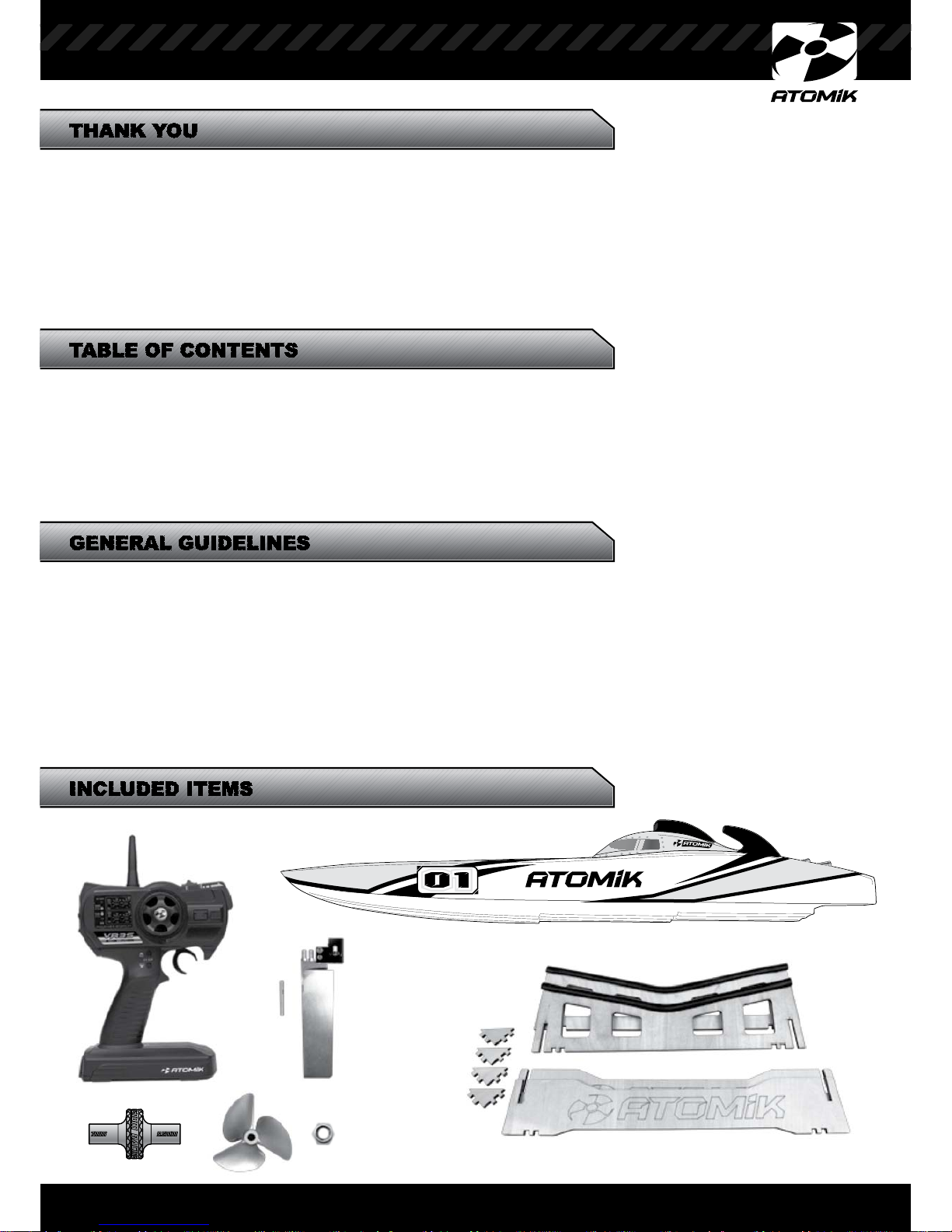
Thank you for purchasing the Atomik™ A.R.C. C1 58”RTR Electric Boat. This RTR Electric Boat was designed with
both beginning RC Boat hobbyists and die hard boat enthusiasts in mind. Racers will love the adjustability and
tunability of the hull and drive system, enthusiasts will enjoy scale realism, and novice hobbyists will enjoy how
easy the Atomik™ A.R.C. C1 58” RTR Electric Boat is to drive. We hope you have as much fun with your Atomik™
RC Electric Boat as we did creating it. Not only did you purchase a top of the line RC Electric Boat, but you have
also joined the Atomik™ Team and world class product line and customer service. Every Atomik™ RC Electric Boat
model boat is hand-made using the latest manufacturing techniques with the highest possible standards. Your
model is unique and may have blemishes due to the nature of the manufacturing process. This is normal, and
further adds to your boats originality.
While the Atomik™ C1 58” RTR Electric Boat is incredibly fun, it is not a toy. It is very important that you read and
follow the steps detailed in this instruction and radio manual. Failure to follow the guidelines detailed in these
manuals could result in damage to property, permanent damage to your model, or personal injury. It is very
important to use this product responsibly. Following these maintenance and operating guidelines will ensure years
of enjoyable use. When operating your model, always keep clear of full-size boats, solid objects, animals and
people. For best results, operate your Atomik™ A.R.C. C1 58”RTR Electric Boat in calm water, low wind conditions
and away from swimmers and wildlife. To avoid an out of control model, always perform a range check. Inspect
your model for damaged props, loose hardware and loose or missing screws before and after every run. If your
model begins to operate erratically or if you notice a change in its operation, stop using it immediately and do not
use again until the issue is corrected.
ESC Setup 4-5
Batteries 6
Boat Stand 6
Rudder Install 7-9
Rudder Servo 10
Water Pickup Lines 10
Propeller Install 11-12
Safety Precautions 2
Specifications 2
Thank You 3
General Guidelines 3
Included Items 3
Required Items 4
Radio 4
Hatch Install 12
Basic Controls 13
Prop Depth Adjust 14
Thrust Angle Adjust 14-15
Pre Run Checklist 16
Transporting Boat 16
Storing Boat 16
Maintenance 17
Parts List 17
Trouble Shooting 18
Warnings 18
Setup Notes 19
Contact Info 20
INCLUDED ITEMS
TABLE OF CONTENTS
TABLE OF CONTENTS
GENERAL GUIDELINES
THANK YOU
THANK YOU
3
Page 4
4
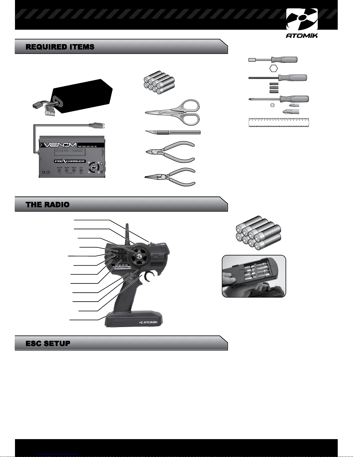
Install 8 AA Batteries
Note: For more detailed instructions, please refer to the
VR3S instruction manual that came with your model.
The water-cooled Atomik™ 120A Pro Marine Brushless Speed Control that came in your Atomik™ A.R.C. C1
58” RTR Electric Boat is pre-programmed from the factory. If you need to re-program it, please follow the
instructions below.
Program the ESC
Use your transmitter to program the ESC in 4 easy steps:
1) Enter program mode
2) Select programmable item
3) Choose the new value of the selected time
4) Exit
Power Switch
Steering Trim
Steering Wheel
Steering EPA
Range Test
REV Switch
Fail Safe
Throttle EPA
ST. Dual Rate
Throttle Trim
Throttle Trigger
Battery Box
AA BATTERIES
1521 AA Rechargeable NiMH
ECOAA8 AA Alkalines
CHARGER
0657 Venom Pro Charger
Curved Scissors
Needle Nosed Pliers
Side Cutters
LiPO BATTERY PACKS
RECOMMENDED BATTERY PACKS
15021 25C 5000mah 22.2V LiPO
15048 50C 5000mah 22.2V LiPO
x8
For Radio
1.5mm
2.0mm
2.5mm
1 2 3 4 5 6 7 8 9 10 11 12 13 14 15 16 17 18 19
Hobby Knife #11 Blade
Screwdriver
No.2
No.1
Nut Driver
5.5mm
Ruler Straight Edge
Hex Driver
REQUIRED ITEMS
ESC SETUP
THE RADIO
THE RADIO
Page 5
5
CAUTION: LOW VOLTAGE CUTOFF
Do not use “NO PROTECTION” when using LiPO battery packs. Monitor the battery pack temperatures after
each run. Do not allow the battery pack temperatures to exceed 120º F/ 52º C while in use. Select a higher low
voltage cutoff setting to help reduce the temperature of the battery packs. It is OK to use “NO PROTECTION”
when using NiCD or NiMH battery packs.
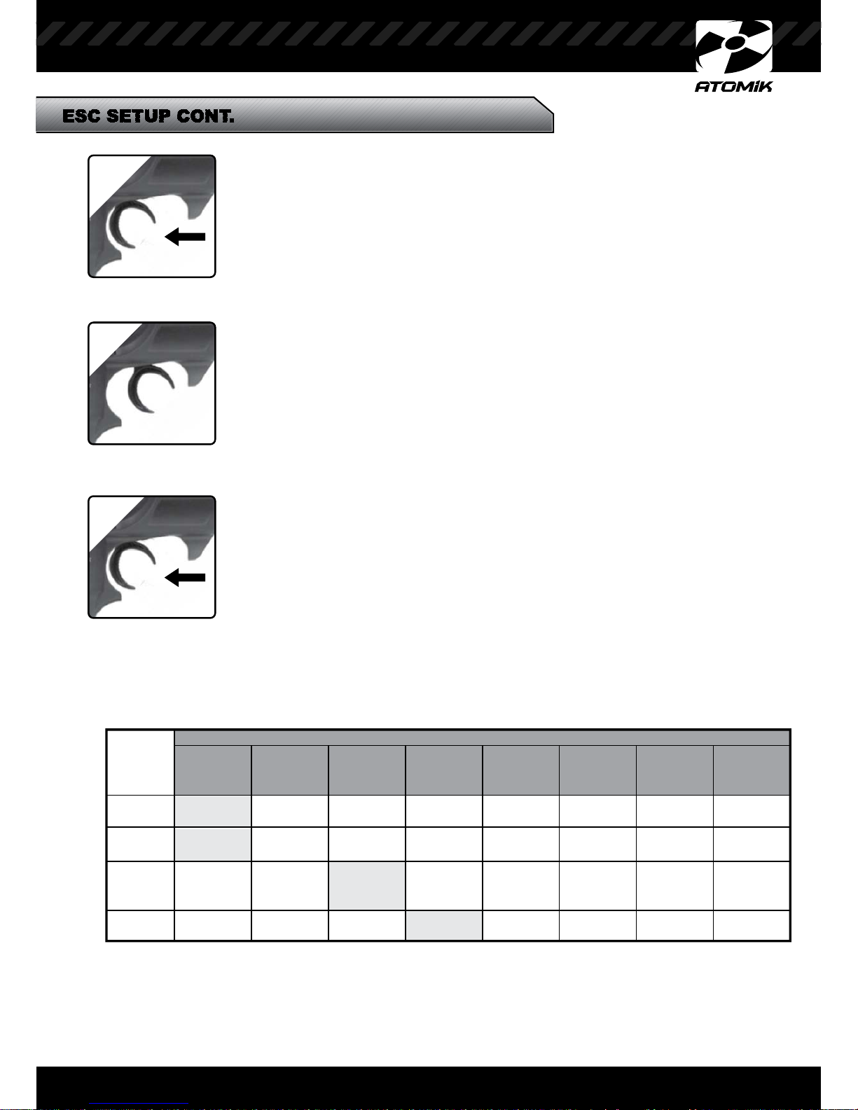
ESC SETUP CONT.
Tuning
Category
Running
Mode
LiPO
Cell #
Low
Voltage
Cutoff
Timing
Forward
Only
Auto
Calculate
No
Protection
0º
Forward &
Backward
2
Cells
2.8V/Cell
3.75º
3
Cells
3.0V/Cell
7.5º
4
Cells
3.2V/Cell
11.25º
5
Cells
3.4V/Cell
15º
6
Cells
18.75º 22.5º 26.25º
BEEP TONES
“B”
1 Short Beep
“BB”
2 Short Beeps
“BBB”
3 Short Beeps
“BBBB”
4 Short Beeps
“Beep-”
1 Long Beep
“Beep-B”
1 Long
1 Short Beep
“Beep-BB”
1 Long
2 Short Beeps
“Beep-BBB”
1 Long
3 Short Beeps
1
FULL THROTTLE
Entering Program Mode
Shaded Fields are Factory Settings (Recommended).
Selecting Category
Selecting Value for Category
If you are unsure if you have exited the program mode, you can disconnect
the battery and your programming will be saved.
2
FULL to NEUTRAL
3
FULL THROTTLE
Turn on transmitter.
Hold full throttle and connect battery.
- Continue to hold full throttle until musical tone sounds (5 seconds).
* CONTINUE TO HOLD FULL THROTTLE WHILE MOVING ON TO STEP 2*
Your ESC will again emit a series of beep tones. The beep tones represent a
dierent value. (Review chart below for tone diagram).
To select a value, simply wait for the desired beep tones to emit and pull full throttle.
Move the throttle to the neutral position. Within 2 seconds you will exit program mode. If you
continue to full throttle position, you will go back to step #2 and you can select a different tuning
category.
The ESC will emit a series of beep patterns. Each pattern represents a category:
To select tuning category, move throttle to neutral after desired beep pattern sounds.
*YOU ARE NOW IN THE SELECTED TUNING CATEGORY*
1. “Beep” Running Mode
2. “Beep-Beep” LiPO Cells
3. “Beep-Beep-Beep” Low Voltage Cutoff Threshold
4. “Beep-Beep-Beep-Beep” Timing
Page 6
6
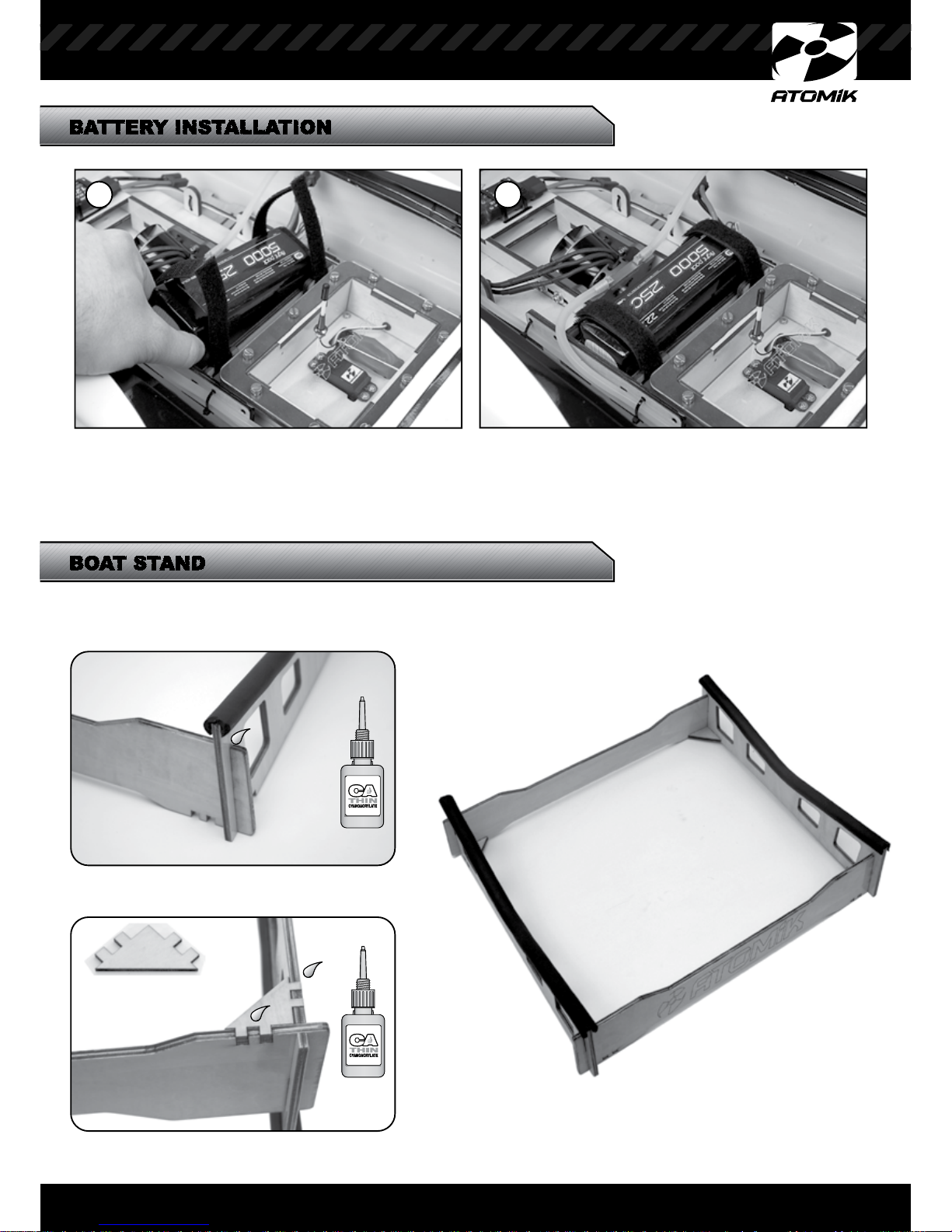
Always use a charger specifically rated to charge your batteries. Charging and discharging batteries has the potential
for serious injury to persons and damage to property. Caution: If batteries get hot during charging, discontinue charging
immediately and disconnect battery from charger. Never leave battery unattended while charging. If you are unsure of how
to charge this battery, please contact Atomik™ or seek the advice of your local hobby shop. Never let children charge
batteries without adult supervision.
BOAT STAND
BATTERY INSTALLATION
1 2
STEP 1
STEP 2
x4
CA Glue
CA Glue
Finished Stand
Page 7
ASSEMBLING THE BOAT
ASSEMBLING THE BOAT
ASSEMBLING THE BOAT
7
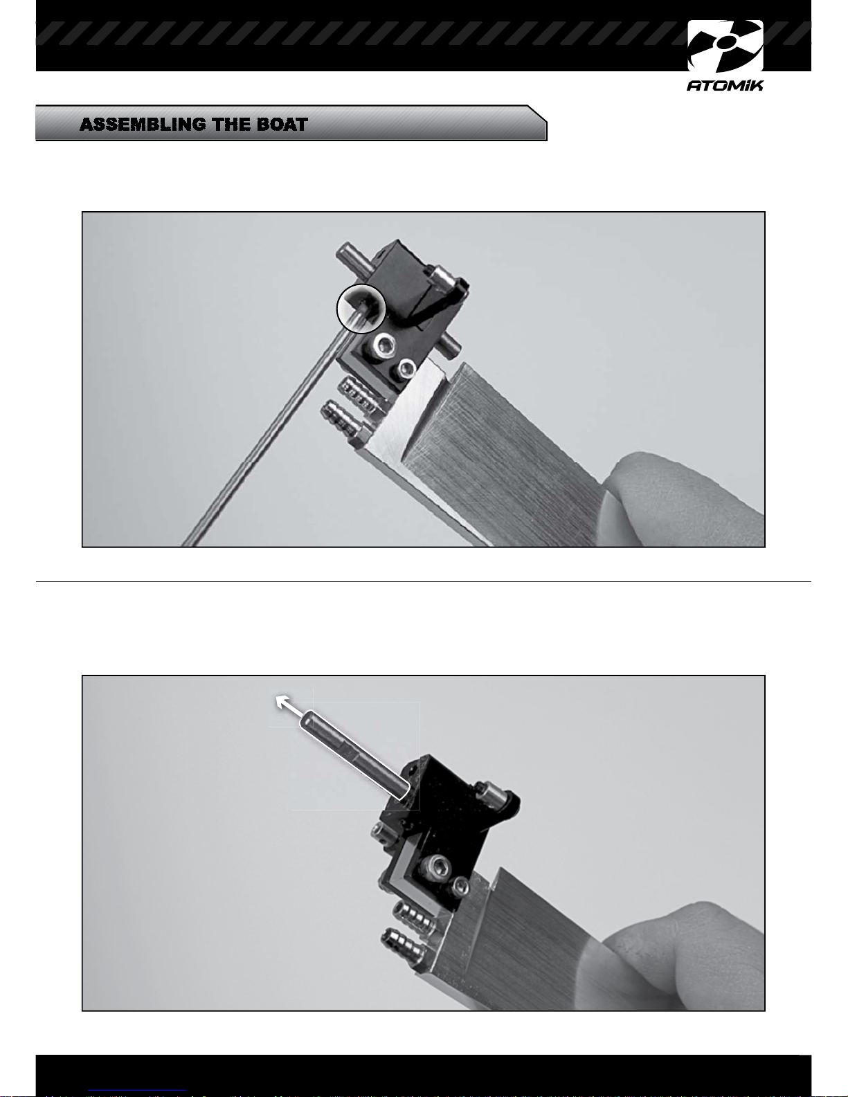
STEP 1
Loosen the set screw using a 2mm hex driver.
STEP 2
Remove the hinge pin
Page 8
PREPPING THE BOAT
8
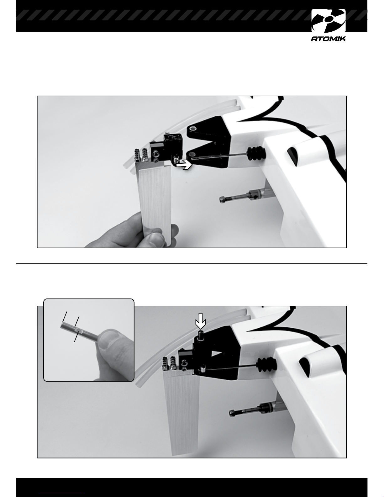
STEP 3
Slide the rudder onto the steering rod.
NOTE TOP Hinge Pin
STEP 4
Align hinge pin holes and insert the hinge pin so that the flat spot is facing the set screw.
FLAT
Page 9
9
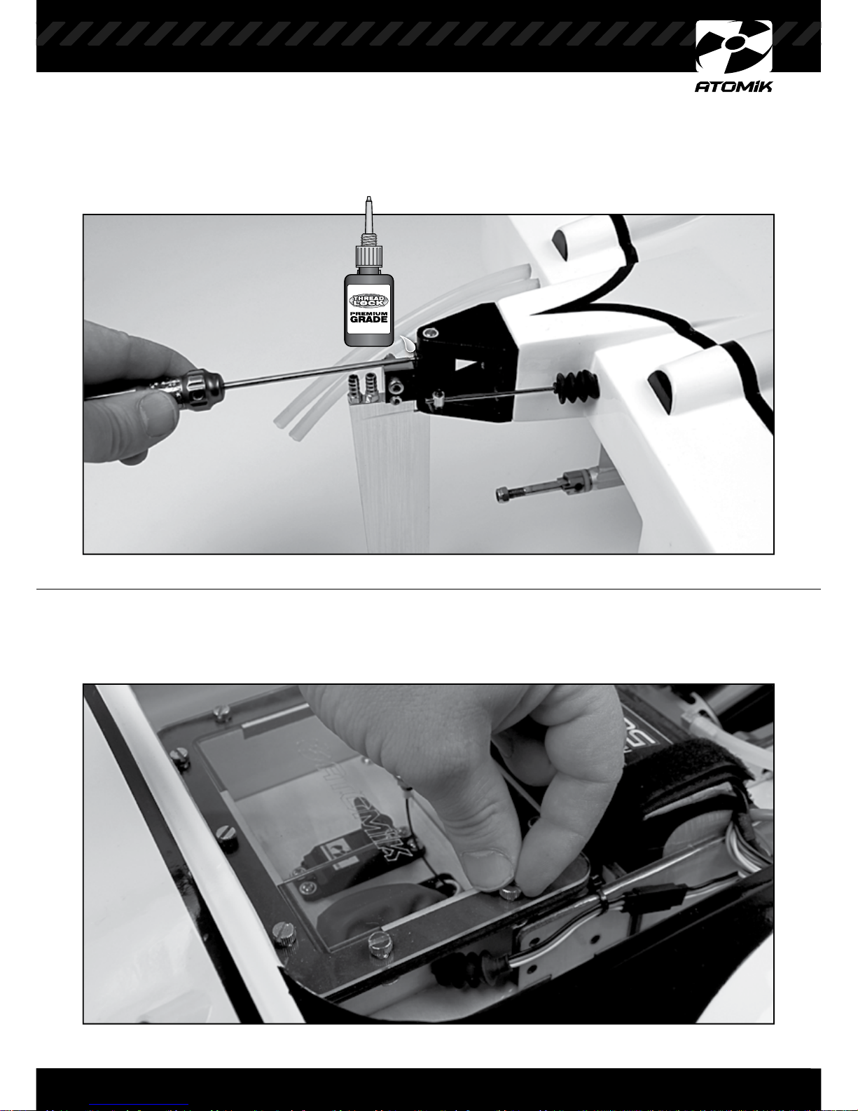
STEP 5
Use a small amount of thread lock to keep the set screw from backing out during use, then
tighten the set screw.
STEP 6
Remove the 8 thumb screws that hold the acrylic radio box cover in place.
Page 10
10
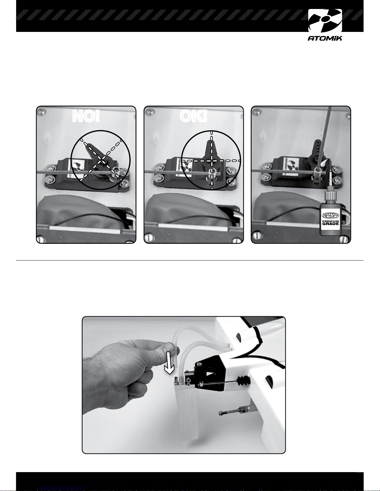
STEP 7
Turn on the transmitter and then the boat to make sure the rudder servo horn is straight.
You can use the steering trim function to help center the servo horn. Use a small amount of
thread lock before tightening the set screws to keep it from backing out during use.
STEP 8
OK!NO! OK!NO!
Attach the clear silicone water-cooling tubes to the water inlet nipple on the top of the rudder.
Make sure the water-cooling tubes are free of kinks and tight bends to ensure that water flows
freely to the motor and ESC to maximize cooling.
Page 11
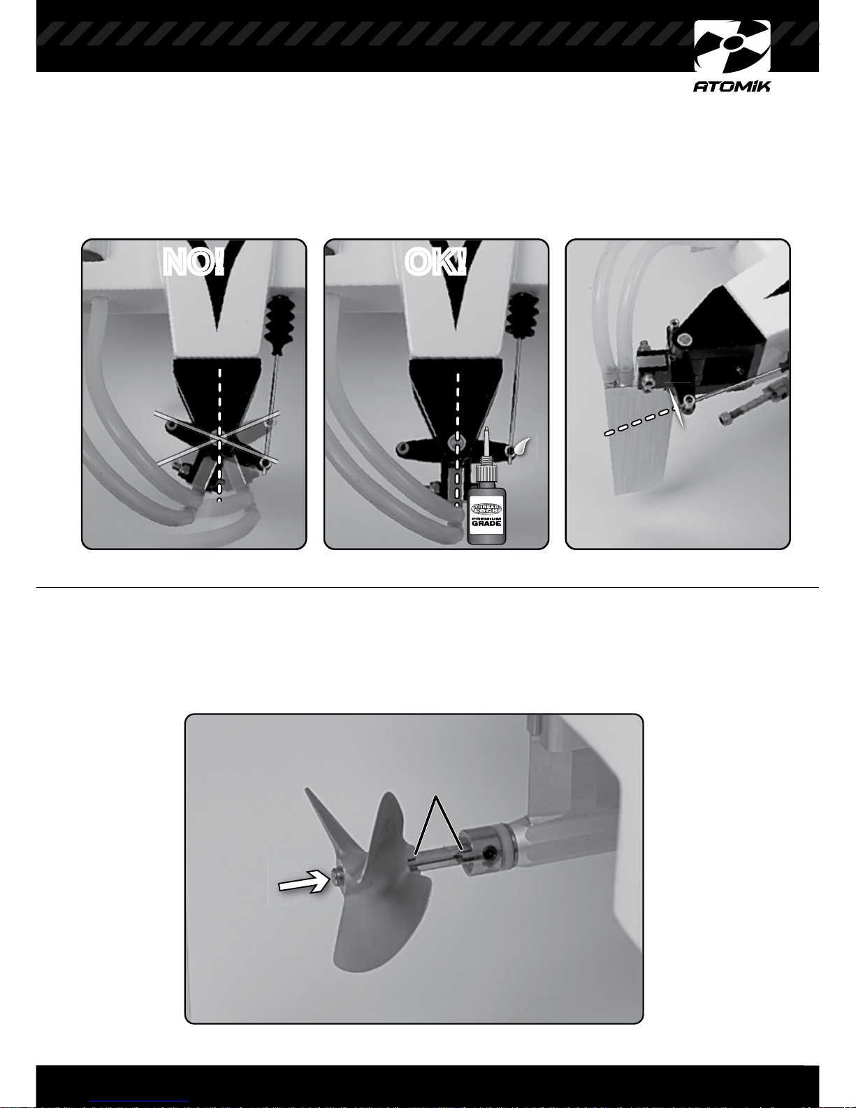
Make sure the rudder is straight before tightening the set screw on the steering rod. Use
a small amount of thread lock to keep the set screw from backing out during use. When the
rudder is straight, use a pair of side cutters to remove the excess length from the steering rods.
11
STEP 9
STEP 10
Slide the prop onto the drive shaft making sure to align the notch.
OK!NO! OK!NO!
Notch
Page 12
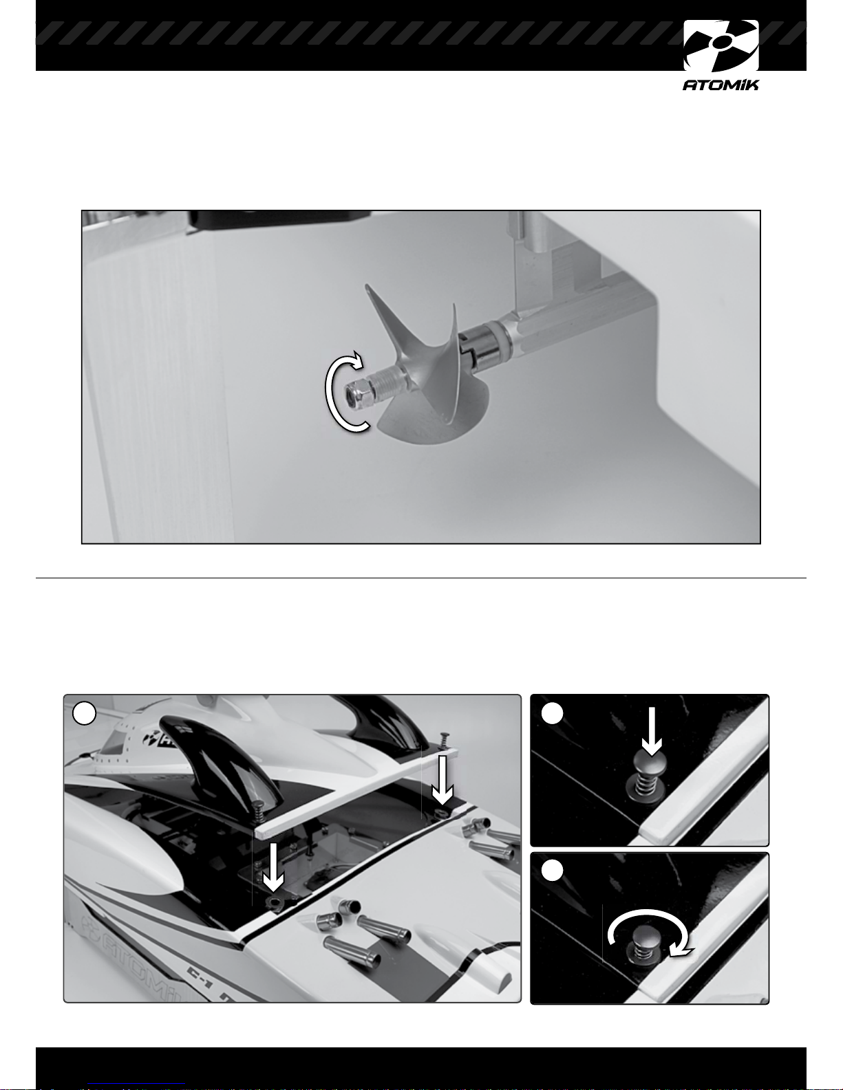
Secure the prop using the 10mm rubber tubing and lock nut. NOTE: Do not over tighten!
Be very carefull when handling the propellor on any model boat. Be sure to disconnect
the battery first.
Secure the hatch by sliding the front tabs into the slots at the front of the hull opening. The
hatch should drop in easily so that the hatch pins seat into the holes in the hull.
Push the pins down with your thumb and rotate them until they lock in place.
12
STEP 11
STEP 12
1 2
3
PRO TIP:
Always inspect the edges of the prop for damage. Keep the edges sharp and clean
for maximum performance.
Page 13
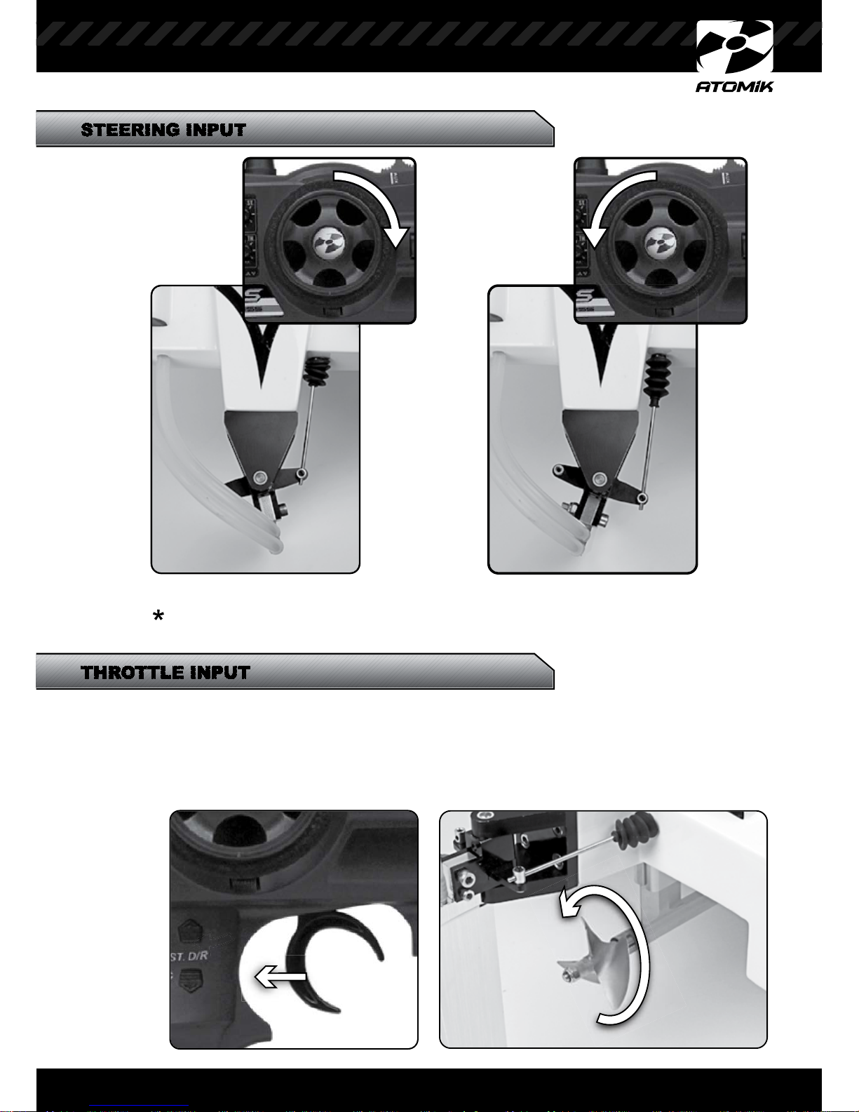
Use the steering dual rate to adjust the steering sensitivity.
Refer to the radio manual that came with your kit for complete instructions.
13
TURN
RIGHT
TURN
LEFT
STEERING INPUT
THROTTLE INPUT
THROTTLE INPUT
THROTTLE INPUT
Check that the motor is operating in the proper direction. The propeller should spin
counter clockwise when viewed from behind the boat. This will require installing batteries in
the transmitter, and boat. Once both are turned on, apply a small amount of power to activate
the motor. Observe the direction. If the motor turns clockwise simply reverse any two of the
three motor wires.
Note:
Turn the
transmitter on
first before
connecting
the battery in
the boat!
Page 14
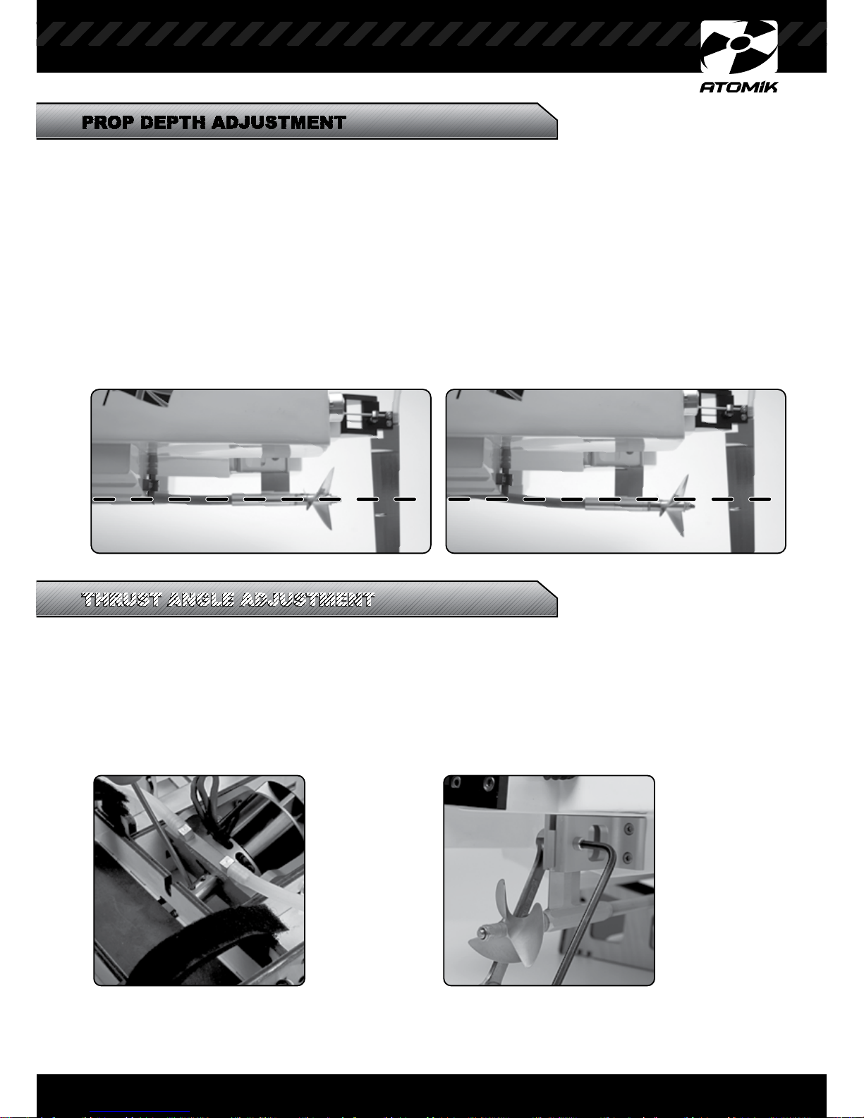
THRUST ANGLE ADJUSTMENT
THRUST ANGLE ADJUSTMENT
14
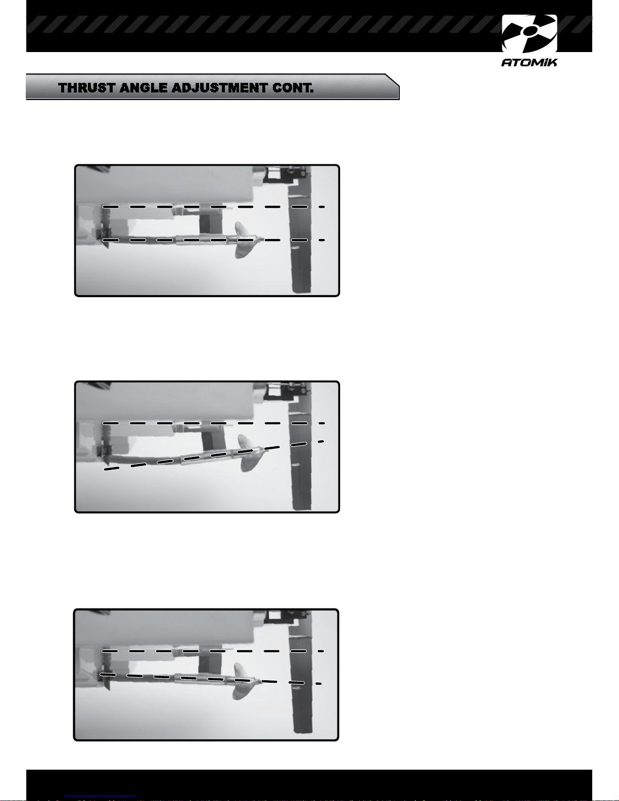
Adjusting the thrust angle of the propeller is a very important tuning aid when you are trying to
get the most performance from your boat. This small adjustment has very big effects. Choose
your setting based on the water conditions and how the boat is responding when cornering and
accelerating.
STEP 1
Loosen the set screws on the
flex cable side of motor adapter
STEP 3
Make the desired angle adjustments to the propeller and then re-tighten the strut pinch bolt
and motor adapter.
STEP 2
Loosen the strut pinch bolt
THRUST ANGLE ADJUSTMENT
THRUST ANGLE ADJUSTMENT
PROP DEPTH ADJUSTMENT
A surface piercing propeller is designed to run halfway below the surface of the water. For
optimum performance, half of the propeller should be in the water at top speed at any thrust
angle. When adjusting the thrust angle, keep in mind to set the propeller depth. From the side
view of the hull, use a yard stick or similar straight edge and place it along the keel to project an
imaginary line past the back of the boat hull or “transom”. This line will then serve as a visual
guide where the water surface will be while the hull is at speed or “on plane”. Adjust the thrust
angle and propeller depth accordingly so that the propeller is halfway below the keel line. This
will provide a base setting and can be further adjusted to find your best setting. A sure sign you
can do better adjusting to the thrust angle and propeller depth is an overly tall rooster tail
following your boat. This is wasted energy shooting water into the air that can otherwise be
doing a better job making your boat go faster. With a proper setting, the roost coming off the
back of the boat will be very low and the boat will be as fast as possible.
Page 15
THRUST ANGLE ADJUSTMENT CONT.
THRUST ANGLE ADJUSTMENT CONT.
THRUST ANGLE ADJUSTMENT CONT.
15
POSITIVE THRUST ANGLE
With a positive setting, the boat will have a tendency to ride with the bow higher than usual. This
setting is useful in smooth water conditions to reach the highest speed possible. The boat will
handle “loose” and can become unstable, so it is better to make small adjustments and find the
optimum performance setting. Remember to write down your settings.
NEGATIVE THRUST ANGLE
With a negative thrust setting, the boat will have a tendency to ride with a bow low attitude. This
setting is useful for rougher water conditions to help keep the boat in the water and under more
control. At higher speeds when cornering there is a side effect of Bow Steering which causes the
boat to over steer or steer aggressively. Too much negative thrust will cause the boat to run “wet”
and limit the top speed.
NEUTRAL THRUST ANGLE (0 DEGREES)
The alignment of the propeller shaft is parallel to the bottom of the hull (keel) which is considered
zero degrees (0 deg) and a neutral setting. The thrust of the propeller is in line with the center of
the hull and has no effect on the hull ride angle.
Page 16
THRUST ANGLE ADJUSTMENT
16
1. Inspect the propeller for any damage. Be sure the propeller is clean, sharp and
balanced.
2. Install the propeller and tighten the nut with care not to over tighten.
3. Inspect all of the running hardware for loose screws and nuts. Make sure they are
secured with blue threadlock.
4. Inspect the cooling lines for any cracks, clogging or wear that can lead to a leak.
5. Install the battery pack making sure it is fully charged.
6. Turn the transmitter ON and perform a radio check from 100 feet away to be sure
the system works. Make sure the transmitter battery pack is fully charged.
7. Make sure the area is clear of people, solid objects and animals before launching
the boat.
1. Remove the propeller to prevent injuries and/or property damage.
2. Remove the battery from the hull.
3. After a day on the water, remove any water from inside the hull.
4. Be sure to place the boat in a safe and secure place to prevent damage to the hull
and running gear.
Take these steps to prevent damage to your boat from long term storage:
1. Remove the battery pack from the boat.
2. Open the boat hatch for a couple of days to a week to allow the moisture to
evaporate. Replace the covers and hatch to keep dust out once the moisture has
evaporated.
3. Remove the propeller to prevent injuries and to keep the propeller in good condition.
Dings and scratches will diminish the performance of your boat. Keep the propeller in
a safe and secure place to ensure maximum performance in the water.
4. Place the boat in a safe place to prevent any accidental damage to the fiberglass
hull. Chips, dings, and scratches will weaken the integrity of the hull and may lead
to a failure while in use.
PRE-RUN CHECKLIST
PRE-RUN CHECKLIST
Page 17

17
BOAT MAINTENANCE
DRIVE LINE
1. Remove the propeller.
2. Loosen the motor coupler set screws for the flex cable.
3. Slide the flex cable out of the drives.
4. Lubricate the flex cable with marine grease.
5. Lubricate the drive ball bearings with a light oil for bearings.
6. Reassemble the drive and wipe away any excess grease and oil.
HULL
1. The hull requires very little maintenance, but must be kept in good condition in order to perform as expected and to
ensure safe operation.
2. Look closely at the exterior surfaces of the hull.
3. Check for damage, chips, cracks and scratches.
4. Determine if damage has weakened the fiberglass and take the appropriate action to fix the
damage. Scratches and hair line cracks are common and typically do not require any attention.
HARDWARE
1. Radio control boats experience high frequency vibrations and as a result the screws, nuts and bolts will become
loose.
2. Check all the motor hardware and motor mounts.
3. Check all running gear, hardware, rudder, drive, steering linkages, hatch quick releases, water-cooling
system, etc.
4. Use thread lock on all metal to metal hardware contacts.
WHAT TO DO AFTER THE BOAT HAS BEEN SUBMERGED
1. Remove the motor and lubricate the bearings on the motor.
2. Remove the electronics.
3. Dry out the interior.
4. The servo, receiver and battery packs will need to be dried out and checked for proper
operation before they are used again.
5. Test the battery pack under load to make sure it is ok to continue regular use.
PARTS LIST
1876 TeflonTube for FlexShaft - King/Segad
1878 5 x 10 Ball Bearing - King/Segad
1883 Rubber Push Rod Seals - King/Segad
1887 Drive Dog - King/Segad
1890 Control Linkage - King/Segad
1891 Water Pickup - King/Segad
1897 Flex Shaft - King/Segad
1898 Scale Rudder Assembly - King/Segad
1907 Strut Assembly - King/Segad
1913 CNC Aluminum Hatch Lock Set
1999 Motor Coupler For 6mm Shaft - EC1
8186 VR3S 3-Channel 2.4GHz Tx/Rx
8188 2.4GHz 3-Channel Micro Receiver
1368 V700 Marine Outrunner - 1100Kv
1396 Pro Brushless Marine 120AMP ESC
15021 25C 6S 5000mAh 22.2V LiPO
15048 50C 6S 5000mAh 22.2V LiPO
1694 EC5 Connector Female - Battery
1695 EC5 Connector Male - Device
1696 EC5 Charge Lead 18”
1792 Hull/Hatch Set - EC1
1793 Propeller 54mm for 58” Electric C1
1794 Motor Mount for 58” Electric C1
1795 Hatch - EC1
1825 High Torque Metal Gear Servo
1885 Alloy Antenna Holder -
King/Seg/EKO
1886 Antenna Tube - King/Seg/EKO
Motor Coupler Set ScrewMotor Coupler Set Screw
Use high quality Marine
Grease to lubricate the
flex cable.
Page 18
All rights reserved. No part of this manual may be reproduced or transmitted in any form by any means, electronic,
mechanical, photocopying, recording, or otherwise, without the prior written permission of Atomik™. For information on
getting permission for reprints and excerpts, contact [email protected].
The information in this manual is distributed on an “As Is” basis, without warranty. While every precaution has been
taken in the preparation of the manual, Atomik™ does not have any liability to any person or entity with respect to any
loss or damage caused or alleged to be caused directly or indirectly by the information contained in this manual or by
the products described in it.
Charging and discharging batteries has the potential for serious injury to persons and damage to property. In purchasing
this product, the user agrees to accept responsibility for all such risks, and will not hold Atomik™, it’s affiliates,
manufacturers, distributors, or retail partners responsible for any accident, injury to persons, or damage to property
resulting from the use of this product. This product contains chemicals known to the State of California to cause cancer,
birth defects and other reproductive harm. Be responsible, dispose of properly.
FCC Warning:
CAUTION: Atomik™ is not responsible for any radio or TV interference caused by unauthorized modifications to this
product. Changes or modifications not authorized by Atomik™ will void all warranties.
NOTE: This product has been tested and found to comply with the limits for a Class B digital device, compliant to Part
15 of the FCC Rules. These limits are designed to provide reasonable protection against harmful interference in a
residential installation. This product generates, uses and can radiate radio frequency energy and, if not installed and
used as instructed, may cause harmful interference to radio communications. However, there is no guarantee that
interference will not occur in a particular installation. If this product does cause harmful interference to radio or television
reception, which can be determined by turning the product on and off, correct the interference by trying one or more of
the following measures:
- Reorient or relocate the receiving antenna.
- Increase the separation between the equipment and receiver.
- Connect the equipment into an outlet on a circuit different from the receiver.
- Consult the dealer or an experienced radio/TV technician for help.
General Warranty Policies
Atomik™ warrants this product to be free of material and workmanship defects when new. Atomik™ will, at its sole
discretion, repair or replace defective components free of charge within 90 days from date of purchase or within 30
days for all electronic components. This warranty does not cover wear and tear, crash damage, modifications, failure
to perform routine maintenance, or any damages arising as a result of improper use. All warranty claims are to be
directed to Atomik™ Customer Service at 1-800-705-0620 (208-762-0620) or [email protected].
Do not hold the back of the boat when launching. The propeller is very sharp and may cause severe injury. Always
disconnect the battery when working on the boat to avoid electric shock. Be very careful, these boats are capable of
reaching high speeds. Make sure you have plenty of open space to run your model.
Important Notice
Atomik™ assumes sole responsibility for our products; therefore, dealers should not be involved in any warranty
issues. All warranty claims are to be directed to Atomik™ Customer Service. Before returning any defective product,
please contact Atomik™ Customer Service at 800-705-0620 (208-762-0620) or [email protected] to
receive a Return Merchandise Authorization Number. A dated & itemized sales receipt must accompany any product
returned for warranty work.
GUARANTEE
All products are inspected and adjusted individually before leaving the manufacturer and are guaranteed to be free of
material defects and manufacturing faults.
18
WARNINGS
WARNINGS
Cause
Speed Control does not operate.
Transmitter and/or receiver is not switched on.
Switch on
C
Improper radio installation.
C
Improper radio installation.
Check connections
4.
D
amag
ed
4.
Repla
ce or
Flex shaft and/or bearings are dirty.
Clean and regrease
disconnected from the motor.
T
TROUBLE SHOOTING
TROUBLE SHOOTING
Page 19

19
SETUP NOTES
Page 20
1814M-1
Atomik RC
14028 N. Ohio Street
Rathdrum, Idaho 83858 USA
Australia
PO Box 7325
Alexandria, NSW 2015
Customer Service
800.705.0620
208.762.0620 (Outside USA)
[email protected]
© Copyright 2012 Atomik RC
www.atomik-rc.com
www.facebook.com/atomik-rc www.twitter.com/Atomik_RC www.youtube.com/atomik-rc
 Loading...