

Page 1

y t i l a u q t s e h g i h e h t f o e r a s t c u d o r p r u o t a h t e r u s n e o t e v i r t s e W
e r f d n a
f i , r e v e w o H . s t r a p g n i s s i m r o s t c e f e d g n i r u t c a f u n a m f o e
, t c u d o r p w e n r u o y h t i w s m e l b o r p y n a e v a h u o y
E R O T S E H T O T T I N R U T E R T O N O D ,
: @ e e r f l l o t s u t c a t n o c e s a e l p
888-996-2729 - 1
1 3 5 3 - 3 7 8 - 6 6 8 - 1 : X A F
m o c . s t r o p s e d a l a c s e @ gameroom
: o t e t i r w r O
s t r o p S e d a l a c s E
t n e m t r a p e D e c i v r e S r e m o t s u C
9 8 8 x o B . O . P
6 0 7 7 4 N I , e l l i v s n a v E
. s t r a p t u o b a g n i r i u q n i n e h w dat e code r u o y e v a h e s a e l P
date code (if , r e b m u n l e d o m r u o y e d i v o r p e s a e l p s t r o p S e d a l a c s E g n i t c a t n o c n e h W
e r a g n i t s e u q e r f i r e b m u n t r a p d n a , ) e l b a c i l p p a
. l a u n a m s r e n w o s i h t n i d n a , g n i g a k c a p , t c u d o r p e h t n o d e t a c o l
G01342W/F
r e b m u N l e d o M r u o Y
Dat e Code:
Purchase Date:
PLEASE RETAIN THIS INSTRUCTION MANUAL FOR FUTURE REFERENCE
All Rights Reserved
2 - G01342W/F - 0416 - WJ
888-996-2729 - 1 l l a C e c i v r e S r e m o t s u C r o F 1 s t r o p S e d a l a c s E 2016©
e r a s r e b m u n e s e h T . t r a p t n e m e c a l p
Page 2
IMPORTANT! READ EACH STEP
IN THIS MANUAL BEFORE YOU
BEGIN THE ASSEMBLY.
TWO
ADULTS ARE REQUIRED TO ASSEMBLE
THIS ATOMIC PROFORCE SOCCER TABLE
Tools Required:
T1 - Allen Wrench (Included)
Phillips Screwdriver
Furniture Polish and Cloth
Assembly Tips
Make sure you understand the following tips before you begin to assemble your soccer table.
1. Start all bolts by hand before tightening.
2. Some drawings or images in this manual may not look exactly like your product. Please
read and understand the text before starting each assembly step.
READ AND FOLLOW ALL ASSEMBLY, OPERATION, AND
SAFETY INSTRUCTIONS CAREFULLY. AT LEAST TWO
ADULTS ARE NEEDED TO PUT THIS SOCCER TABLE
TOGETHER.
All Rights Reserved.
©
2016 Escalade Sports
2
For Customer Service Call 1-888-996-2729
Page 3
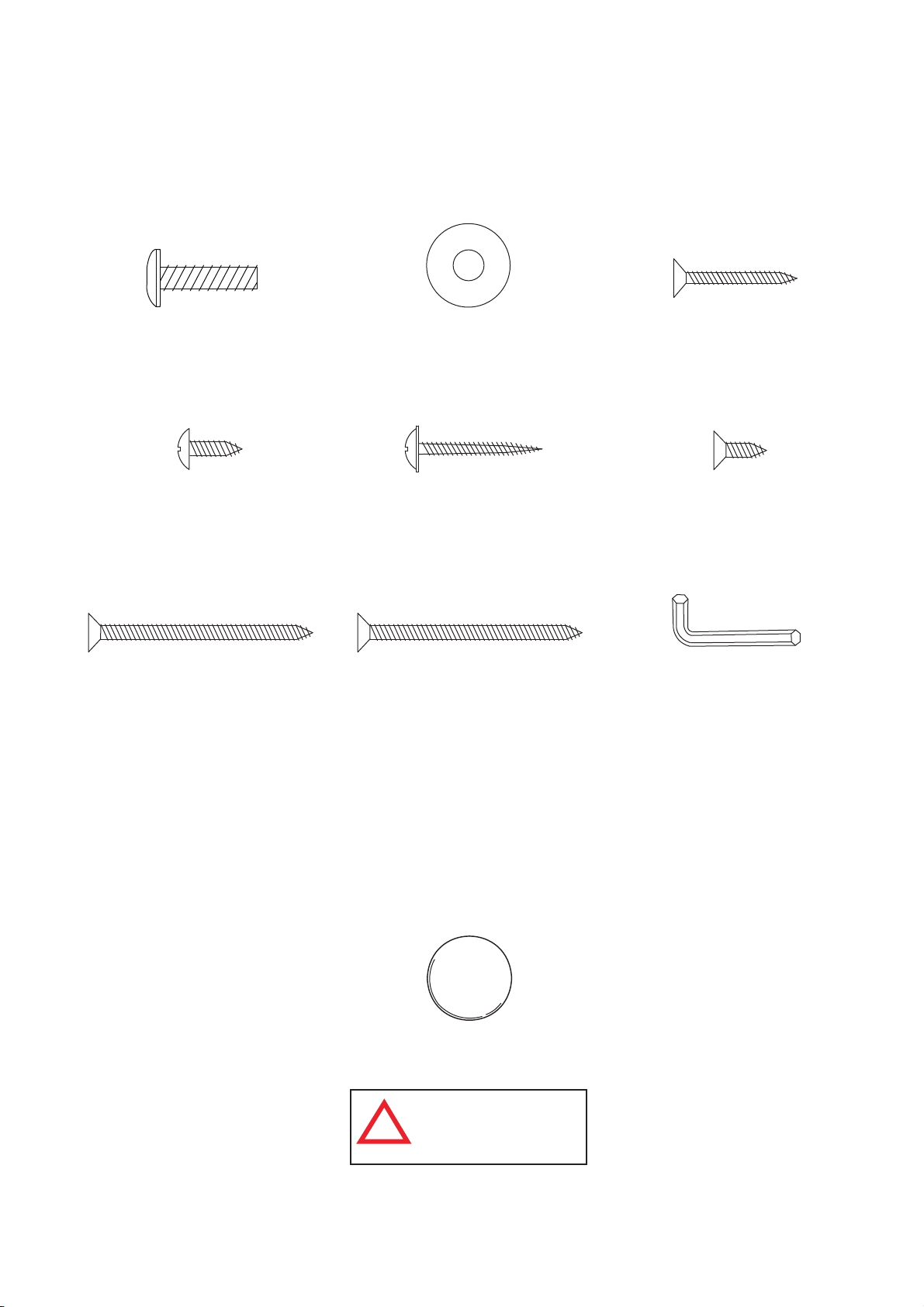
HARDWARE IDENTIFIER
( To Scale)
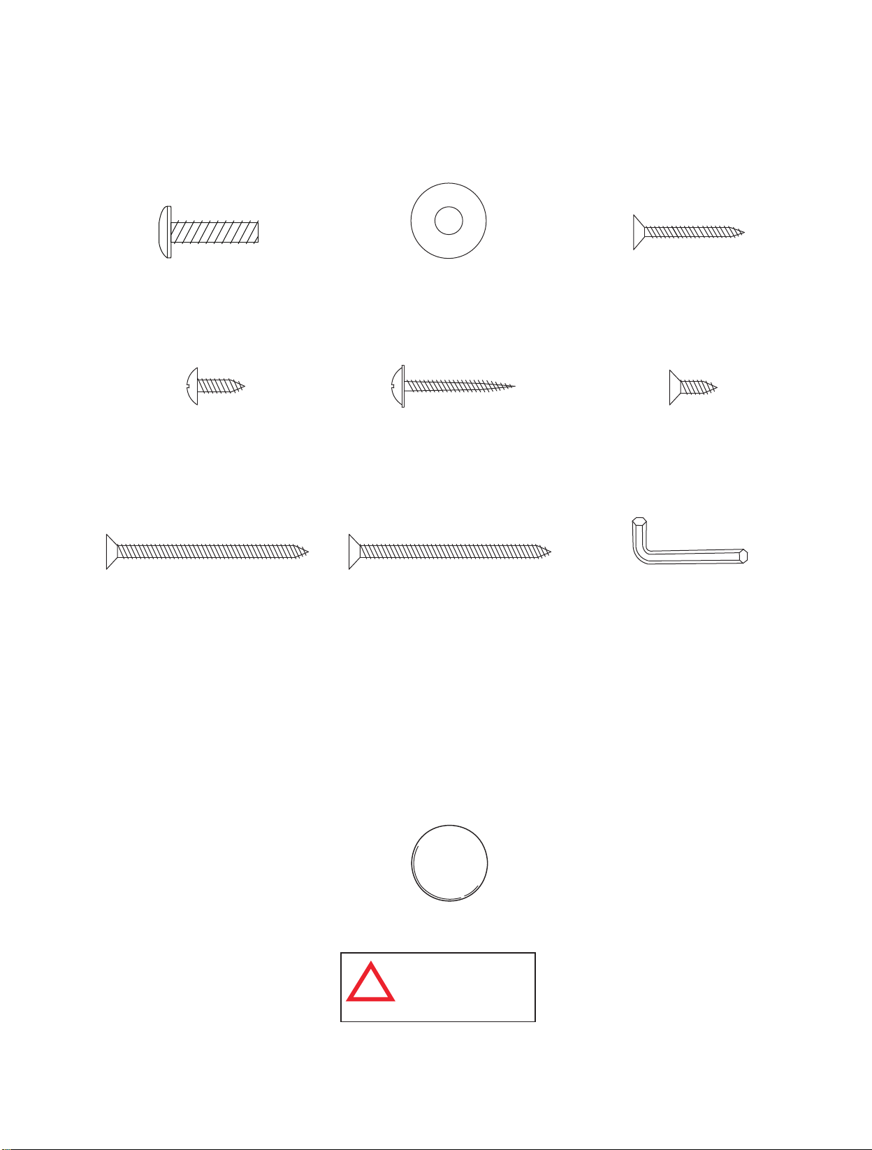
H1 - 6mm x 22mm
Allen Head Bolt
(16 pcs)
H4 - 4mm x 12mm
Phillips Round Head
Screw (84 pcs)
H7 - 4mm x 51mm
Phillips Flat Head
Screw (12 pcs)
H2 - 6mm x 19mm
Flat Washer (16 pcs)
H5 - 3mm x 28mm
Phillips Washer Head
Screw (18 pcs)
H8 - 4mm x 51mm
Zinc - Phillips Flat Head
Screw (4 pcs)
H3 - 3mm x 28mm
Phillips Flat Head
Screw (8 pcs)
H6 - 4mm x 12mm
Phillips Flat Head
Screw (6 pcs)
(Not to Scale)
T1 - Allen Wrench
(1 pc)
All Rights Reserved.
©
2016 Escalade Sports
ACCESSORIES IDENTIFIER
( Not to Scale)
A1- Soccer Ball (4 pcs)
WARNING:
CHOKING HAZARD
!
Small parts.
Not for children under 3 yrs.
3
For Customer Service Call 1-888-996-2729
Page 4
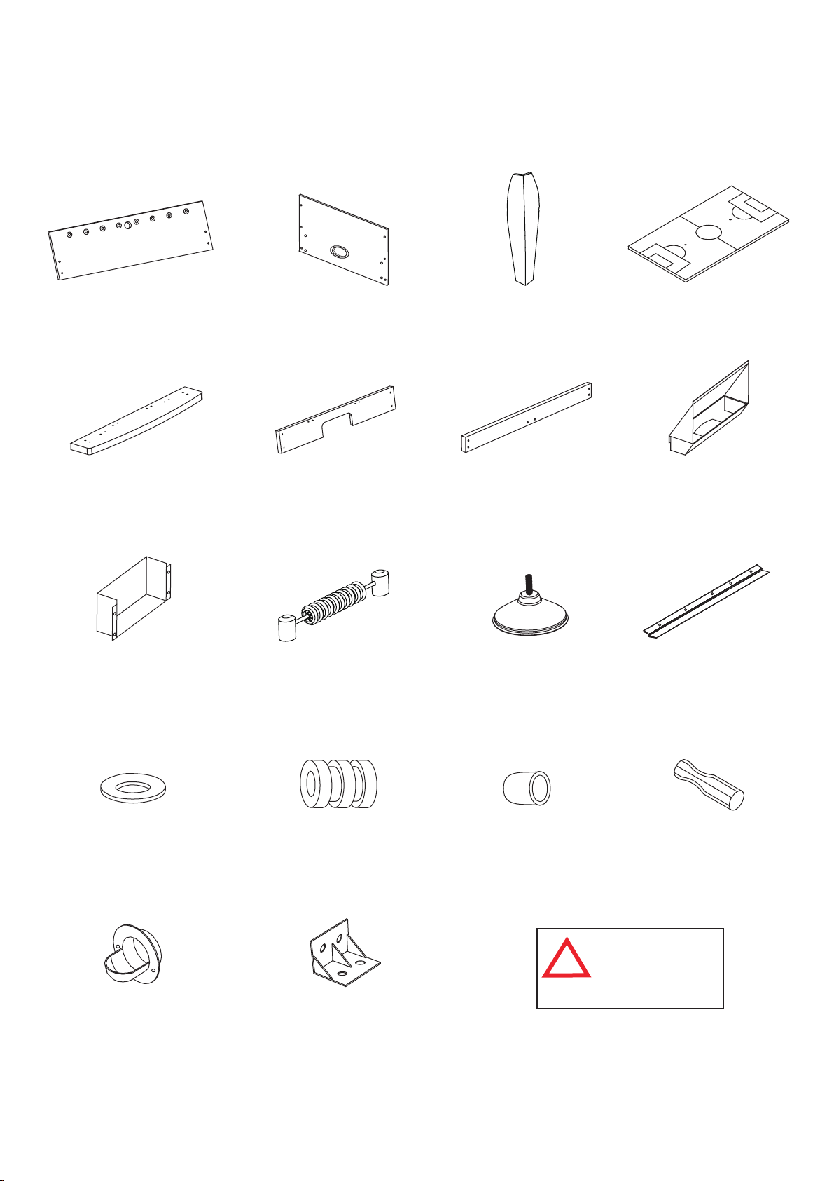
PARTS IDENTIFIER
( Not to Scale)
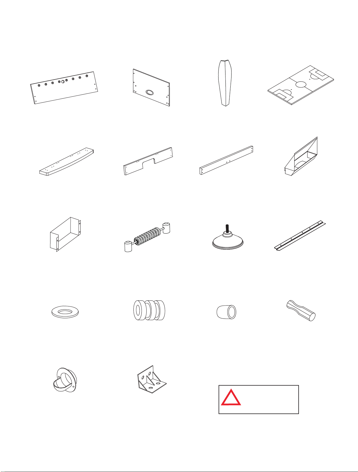
P1 - Side Apron
(2 pcs)
P5 - End Top Rail
(2 pcs)
P9 - Bottom Goal
Box (2 pcs)
P2 - End Apron
(2 pcs)
P6 - Goal End
Board (2 pcs)
P10 - Scorer (2 pcs)
P3 - Leg (4 pcs)
P7 - Playfield Support
Brace (2 pcs)
P11 - Leg Leveler
(4 pcs)
P4 - Playfield (1 pc)
P8 - Top Goal
Box (2 pcs)
P12 - Playfield
Trim (2 pcs)
P13 - Plastic Rod
Washer (16 pcs)
P17 - Outside Ball
Entry Cup (2 pcs)
All Rights Reserved.
©
2016 Escalade Sports
P14 - Rod Bumper
(16 pcs)
P18 - Plastic
Bracket (18 pcs)
P15 - Rod End
Cap (8 pcs)
P16 - Rod Handle
(8 pcs)
WARNING:
CHOKING HAZARD
!
Small parts.
Not for children under
3 yrs.
4
For Customer Service Call 1-888-996-2729
Page 5
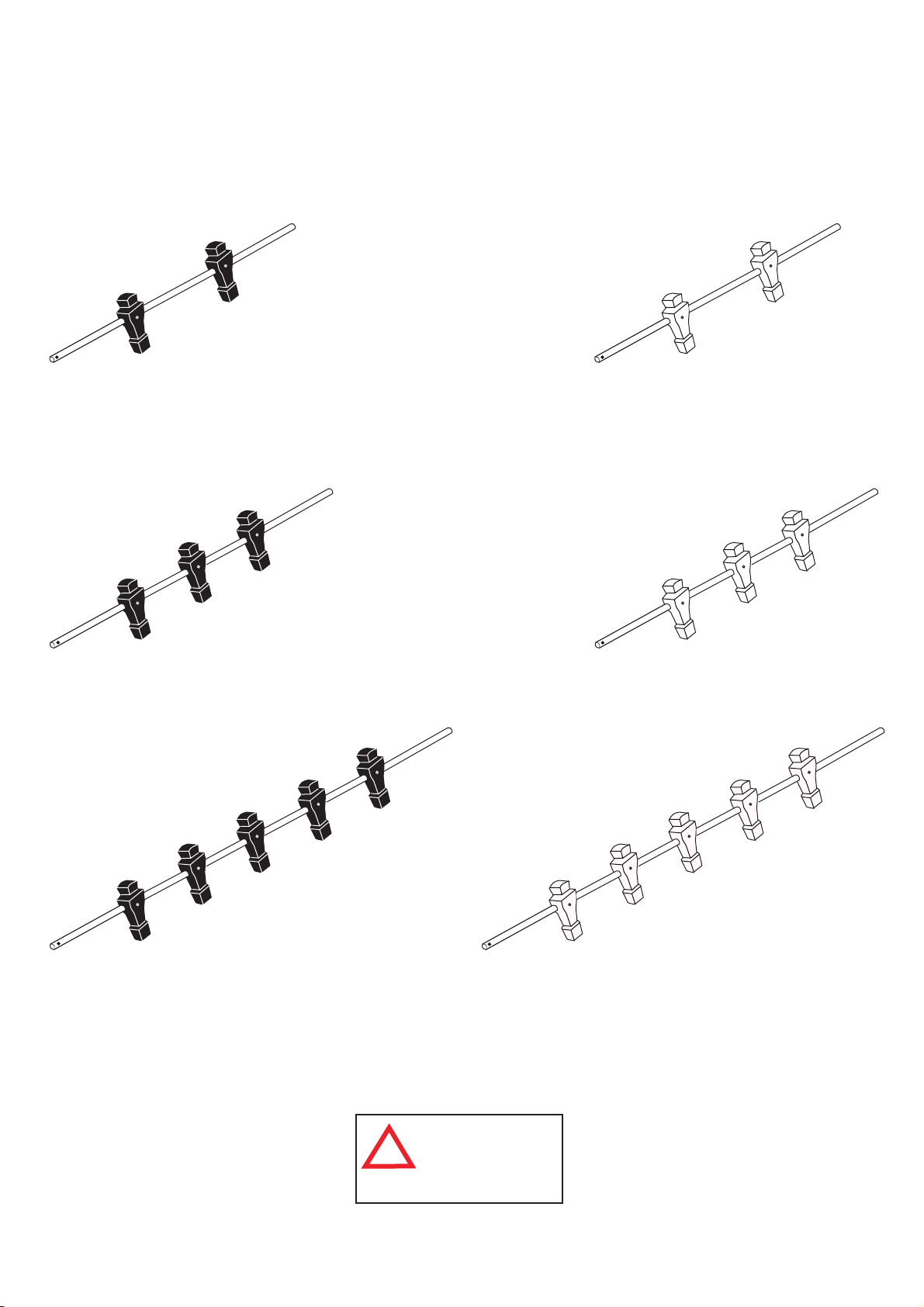
ROD IDENTIFIER
( Not to Scale)
R1 - 2 Player Rod
Assembly Black (1 pc)
R2 - 3 Player Rod
Assembly Black (2 pcs)
R4 - 2 Player Rod
Assembly Ivory (1 pc)
R5 - 3 Player Rod
Assembly Ivory (2 pcs)
R3 - 5 Player Rod
Assembly Black (1 pc)
All Rights Reserved.
©
2016 Escalade Sports
WARNING:
CHOKING HAZARD
!
Small parts.
Not for children under
3 yrs.
5
R6 - 5 Player Rod
Assembly Ivory (1 pc)
For Customer Service Call 1-888-996-2729
Page 6
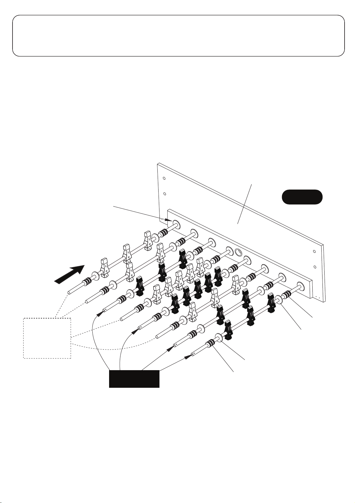
PARTS REQUIRED:
1 pc - P1 Side Apron 1 pc - R1 2 Player Rod Assembly Black 1 pc - R4 2 Player Rod Assembly Ivory
16 pcs - P13 Plastic Rod Washer 2 pcs - R2 3 Player Rod Assembly Black 2 pcs - R5 3 Player Rod Assembly Ivory
16 pcs - P14 Rod Bumper 1 pc - R3 5 Player Rod Assembly Black 1 pc - R6 5 Player Rod Assembly Ivory
STEP 1:
Find a clean, level place to begin the assembly of your soccer table. We recommend building the table on the
box top to protect the parts during assembly.
Attach P13 Plastic Rod Washer and P14 Rod Bumper to the rods as shown in FIGURE 1. Place one P1 Side
Apron UPSIDE DOWN with the laminated side facing out as shown in FIGURE 1.
Align the rods as shown in FIGURE 1.
Please note the location of the hole that is near one end of each rod. This is the handle end of the rod.
There will be four handles on each side of the table. It is critical that you set the rods as shown below so
the table will be correct when flipped over.
C1 Rod Bushing
Note: C1 Rod Bushings
are already attached
onto P1 Side Apron
R4, R5 and R6
Hole/Handle
goes on the
other end of
these rods
R5
R4
R2
R6
R3
R5
R1
R2
P1
FIGURE 1
P14
P13
P13
All Rights Reserved.
©
2016 Escalade Sports
R1, R2 and R3
Hole/Handle End
P14
6
For Customer Service Call 1-888-996-2729
Page 7
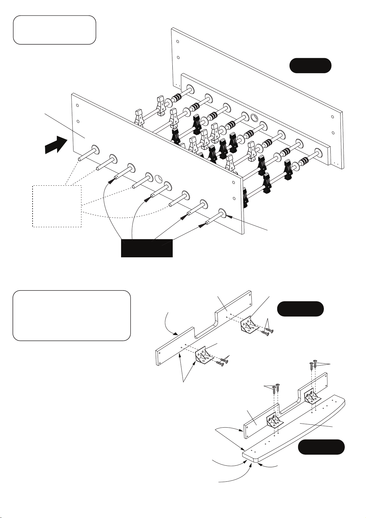
PARTS REQUIRED:
1 pc - P1 Side Apron
STEP 2:
Once your are sure you have the rods set
correctly, slide the other P1 Side Apron on
the rods as shown in FIGURE 2.
P1
R5
R4
R2
R4, R5 and R6
Hole/Handle
goes on the
other end of
these rods
R6
R1, R2 and R3
Hole/Handle End
R3
R5
R1
R2
FIGURE 2
C1 Rod Bushing
Note: C1 Rod Bushings
are already attached
onto P1 Side Apron
PARTS REQUIRED:
16 pcs - H4 Phillips Round Head Screw
2 pcs - P5 End Top Rail
2 pcs - P6 Goal End Board
4 pcs - P18 Plastic Bracket
STEP 3:
Place two P18 Plastic Brackets onto each inside
end of P6 Goal End Board as shown and attach
using the pre-drilled pilot holes with H4 Screws
as shown in FIGURE 3A.
Tighten, but do not strip out H4 screws.
NOTE: Be sure bottom edge of P18 Plastic
Brackets is flush with bottom edge of board.
Next, attach this assembly to P5 End Top Rail
using pre-drilled pilot holes with H4 Screws as
shown in FIGURE 3B.
Tighten, but do not strip out H4 screws.
NOTE: Be sure bottom edge of P6 Goal End
Board is flush with bottom edge of P5 Top Rail.
Repeat procedure for second assembly.
All Rights Reserved.
©
2016 Escalade Sports
P6
White laminate
this side
Edge must be
flush for correct
assembly
Edge must be
flush for correct
assembly
Black laminate
on bottom side
NOTE: See STEP 4 to look at
correct assembly P5 and P6.
7
P18
FIGURE 3A
H4
P18
H4
H4
H4
P6
P5
FIGURE 3B
Round Corner
this position
For Customer Service Call 1-888-996-2729
Page 8
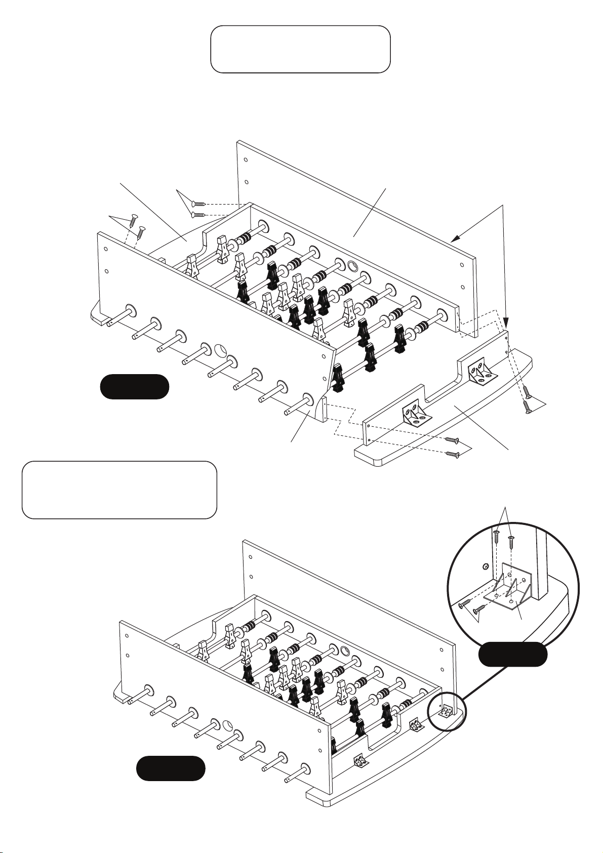
PARTS REQUIRED:
8 pcs - H3 Phillips Flat Head Screw
STEP 4:
Attach P5/P6 assemblies from STEP 3 to P1 Side Apron using pre-drilled pilot holes with H3 Screws as shown
in FIGURE 4. Tighten, but do not strip out H3 Screws.
IMPORTANT NOTE: The holes are pre-drilled at an ANGLE on purpose, be sure to allow H3 Screws to follow
pre-drilled holes.
P5/P6
Assembly
H3
H3
FIGURE 4
PARTS REQUIRED:
16 pcs - H4 Phillips Round Head Screw
4 pcs - P18 Plastic Bracket
P1
P1
IMPORTANT NOTE:
Be sure to keep this assembly
square during P5/P6 assembly.
H3
H3
P5/P6
Assembly
H4
STEP 5:
Install one piece P18 Plastic Bracket
into each inside corner of P1 Side Apron
using pre-drilled pilot holes and H4
screws as per FIGURE 5 and DETAIL A.
Tighten, but do not strip out H4 screws.
FIGURE 5
All Rights Reserved.
©
2016 Escalade Sports
H4
P18
DETAIL A
8
For Customer Service Call 1-888-996-2729
Page 9
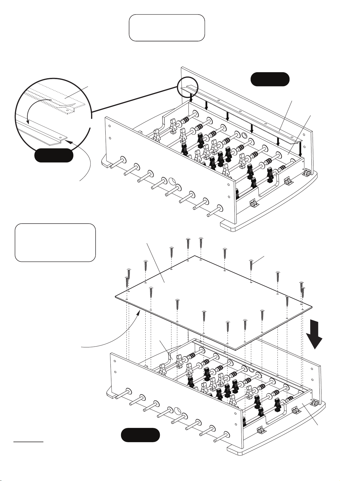
PARTS REQUIRED:
2 pcs - P12 Playfield Trim
STEP 6:
Carefully peel the protective film strips off of the 3 pieces of adhesive tape on the underside of both P12 Playfield
Trims. Turn them over and carefully place them along P1 Side Aprons as shown in DETAIL B and FIGURE 6.
FIGURE 6
P12
P12
P1
Peel and Turn Over
DETAIL B
NOTE: Adhesive
strip this side.
PARTS REQUIRED:
18 pcs - H5 Phillips Washer
Head Screw
1 pc - P4 Playfield
STEP 7:
Place P4 Playfield with graphics
facing down onto the main cabinet.
Align P4 Playfield holes with P12
Playfield Trims holes and attach
using H5 Screws as shown in
FIGURE 7.
Tighten, but
Screws.
IMPORTANT NOTE:
P4 Playfield must be evenly
spaced on top of both ends
of P6 Goal End Board - at each
end of cabinet assembly.
do not strip out H5
Graphic
facing down
P4
H5
P6
P1 Side Aprons may be slightly
warped. Please keep P1 Side
Aprons pushed in tight against
the P4 Playfield for correct assembly.
All screws must be screwed
STRAIGHT down.
All Rights Reserved.
©
2016 Escalade Sports
FIGURE 7
P6
9
For Customer Service Call 1-888-996-2729
Page 10
PARTS REQUIRED:
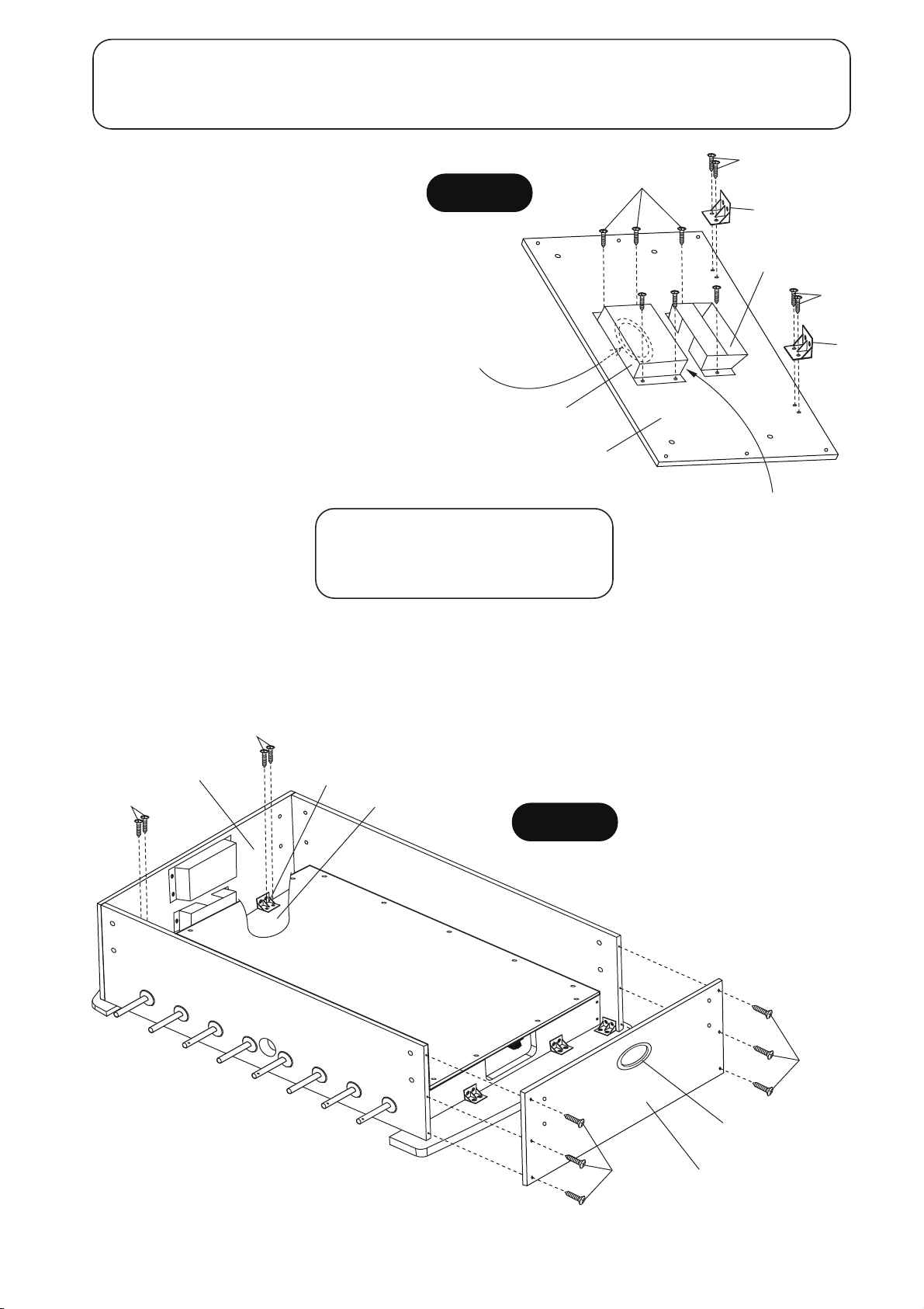
20 pcs - H4 Phillips Round Head Screw 2 pcs - P8 Top Goal Box 4 pcs - P18 Plastic Bracket
2 pcs - P2 End Apron 2 pcs - P9 Bottom Goal Box
STEP 8:
Attach P18 Plastic Brackets onto the back side
of P2 End Apron using pre-drilled pilot holes
with H4 Screws as shown in FIGURE 8.
Tighten, but do not strip out H4 screws.
NOTE: Be sure bottom edge of P18 Plastic
Brackets is flush with bottom edge of apron.
Attach P8 Top Goal Box and P9 Bottom Goal
Box onto the back side of P2 End Apron using
pre-drilled holes with H4 Screws as shown in
FIGURE 8.
Tighten, but do not strip out H4 screws.
Repeat procedure for second assembly.
PARTS REQUIRED:
8 pcs - H4 Phillips Round Head Screw
12 pcs - H7 Phillips Flat Head Screw
FIGURE 8
NOTE:
Ball Opening
in P2 End Apron
must be in this
position.
H4
H4
P18
P8
H4
P18
P9
P2
NOTE:
Opening of P9 Bottom Goal
Box must be in this position.
STEP 9:
Attach previous assemblies from STEP 8 to the end of table cabinet using pre-drilled pilot holes with H7 Screws
as shown in FIGURE 9. Tighten, but do not strip out H7 screws.
Install H4 Screws into previously installed P18 Plastic Brackets as shown in FIGURE 9.
Tighten, but do not strip out H4 screws.
H4
STEP 8
Assembly
H4
P18
P5
FIGURE 9
H7
All Rights Reserved.
©
2016 Escalade Sports
10
C2
H7
STEP 8
Assembly
For Customer Service Call 1-888-996-2729
Page 11
PARTS REQUIRED:
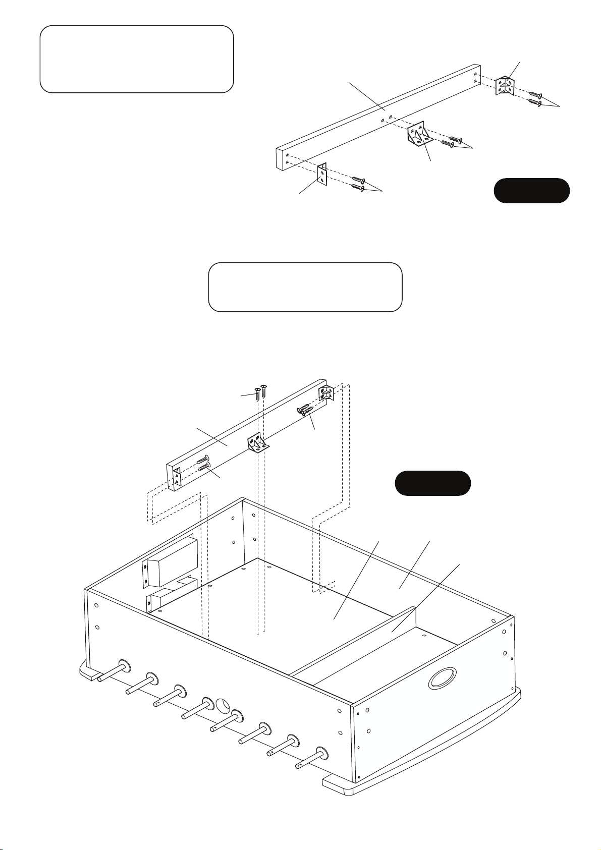
12 pcs - H4 Phillips Round Head Screw
2 pcs - P7 Playfield Support Brace
6 pcs - P18 Plastic Bracket
P18
P7
STEP 10:
Attach P18 Plastic Brackets onto P7 Playfield
Support Braces using pre-drilled pilot holes
with H4 Screws as shown in FIGURE 10.
Tighten, but do not strip out H4 screws.
NOTE: Be sure bottom edge of all P18 Plastic
P18
P18
H4
H4
FIGURE 10
Brackets are flush with the edge of P7 Support
Braces.
PARTS REQUIRED:
12 pcs - H4 Phillips Round Head Screw
STEP 11:
Attach previous assembly STEP 10 onto P3 Playfield and P1 Side Aprons using pre-drilled pilot holes with H4
Screws as shown in FIGURE 11. Tighten, but do not strip out H4 screws.
NOTE: Be sure plastic brackets are facing each other for correct assembly.
H4
H4
STEP 10
Assembly
H4
H4
P3
FIGURE 11
P1
STEP 10
Assembly
All Rights Reserved.
©
2016 Escalade Sports
11
For Customer Service Call 1-888-996-2729
Page 12
PARTS REQUIRED:
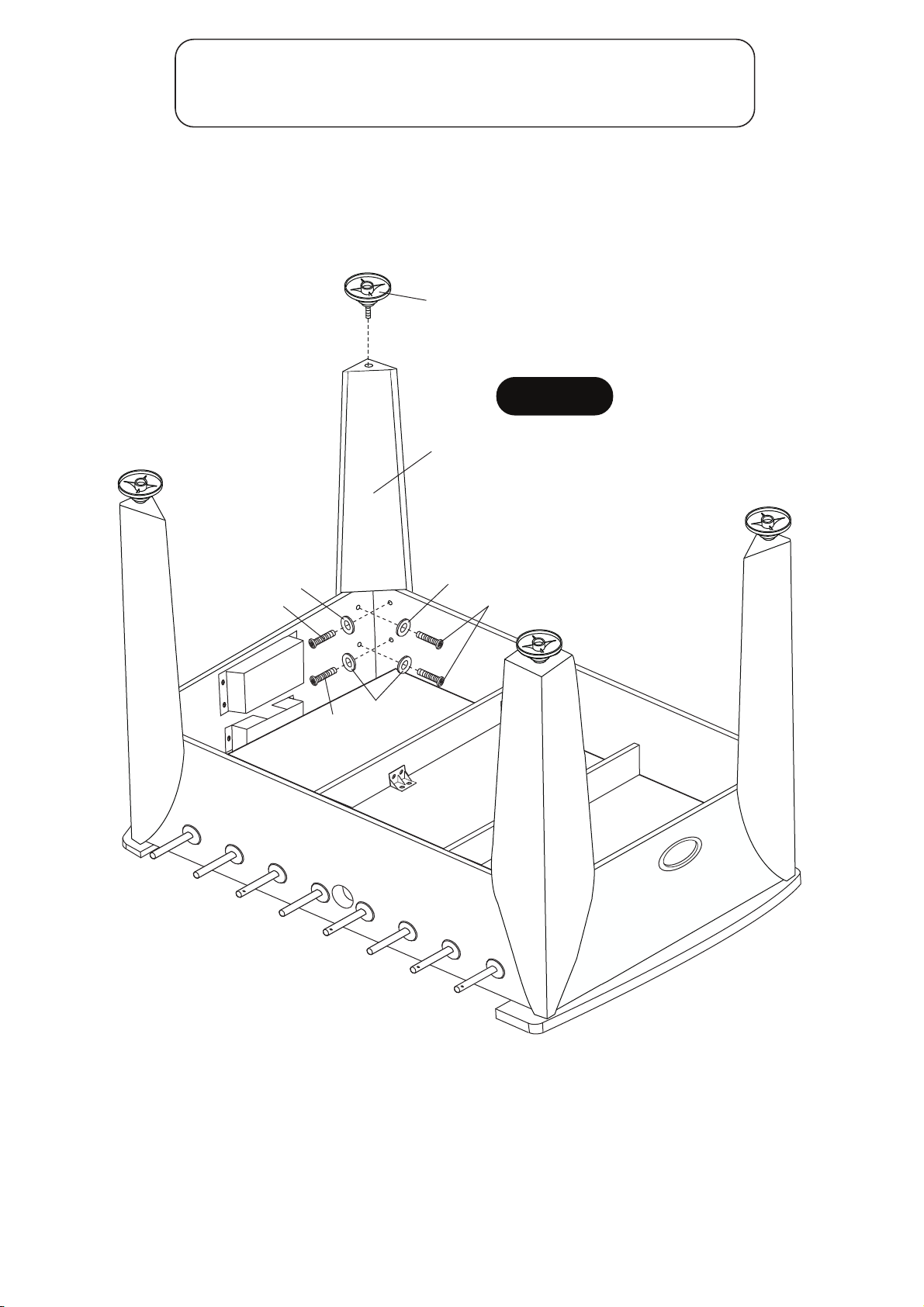
16 pcs - H1 Allen Head Bolt 4 pcs - P3 Leg 1 pc - T1 Allen Wrench
16 pcs - H2 Flat Washer 4 pcs - P11 Leg Leveler
STEP 12:
Attach P3 Legs using H1 Allen Head Bolts with H2 Flat Washers as shown in FIGURE 12.
Use T1 Allen Wrench to tighten all bolts.
Thread P11 Leg Levelers to each P3 Leg as shown in FIGURE 12.
P11
FIGURE 12
P3
H1
H2
H2
H1
H2
H1
All Rights Reserved.
©
2016 Escalade Sports
12
For Customer Service Call 1-888-996-2729
Page 13
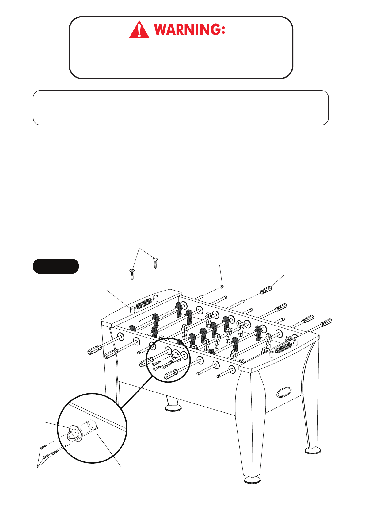
THIS STEP REQUIRES FOUR OR MORE ADULTS.
VERY CAREFULLY TURN THE TABLE OVER AND SET IT ON
ITS LEGS. BE CAREFUL. THE TABLE IS VERY HEAVY.
PARTS REQUIRED:
6 pcs - H6 Phillips Flat Head Screw 2 pcs - P10 Scorer 8 pcs - P16 Rod Handle
4 pcs - H8 Zinc-Phillips Flat Head Screw 8 pcs - P15 Rod End Cap 2 pcs - P17 Ball Entry Cup
STEP 13:
Attach P10 Scorers onto the top of P5 End Top Rails using H8 Screws as shown in FIGURE 13.
Tighten, but do not strip out H8 screws.
Attach P15 Rod End Caps to the rod as shown in FIGURE 13.
Slide P16 Rod Handle onto each rod end with the small hole shown in FIGURE 13.
IMPORTANT NOTE: A small amount of liquid soap applied inside each P16 Rod Handle will allow them to
slip onto rod easier.
Attach P17 Ball Entry Cups onto P1 Side Aprons using H6 Screws as shown in FIGURE 13.
Tighten, but do not strip out H6 screws.
FIGURE 13
P17
P10
H8
P15
Note:
Small
Hole
P16
H6
All Rights Reserved.
©
2016 Escalade Sports
P1
13
For Customer Service Call 1-888-996-2729
Page 14
Congratulations! You have now assembled your soccer table. Please note the Care and Use
instructions below to insure many years of trouble free use of your soccer table.
CARE AND USE OF YOUR ATOMIC PROFORCE SOCCER TABLE
1. Apply spray furniture polish to a clean cloth and wipe down the rods to make them slide
easier in the rod bushings.
2. Use spray furniture polish to clean all exterior surfaces of your soccer table.
3. Use a carpenters level to properly level table using the leg levelers.
4. This product is intended for INDOOR use only.
5. DO NOT sit, climb or lean on the table.
6. DO NOT drag the table when moving it. This will damage the legs.
7. DO NOT set drinks on the table.
PRODUCT PARTS LIST FOR MODEL # G01342W
Key # Part #
H1
H2
H3
H4
H5
H6
H7
H8
T1
A1
P1
P2
P3
P4
P5
P6
P7
P8
P9
P10
P11
P12
P13
P14
P15
P16
P17
P18
C1
C2
C3
C4
C5
C6
C7
C8
C9
K1
M1
01342WJH1
01342WJH2
01342WJH3
01342WJH4
01342WJH5
01342WJH6
01342WJH7
01342WJH8
01342WJT1
01342WJA1
01342WJP1
01342WJP2
01342WJP3
01342WJP4
01342WJP5
01342WJP6
01342WJP7
01342WJP8
01342WJP9
01342WJP10
01342WJP11
01342WJP12
01342WJP13
01342WJP14
01342WJP15
01342WJP16
01342WJP17
01342WJP18
01342WJC1
01342WJC2
01342WJC3
01342WJC4
01342WJC5
01342WJC6
01342WJC7
01342WJC8
01342WJC9
01342WJK1
01342WJM1
Description
6mm x 22mm Allen Head Bolt
6mm x 19mm Flat Washer
3mm x 28mm Phillips Flat Head Screw
4mm x 12mm Phillips Round Head Screw
3mm x 28mm Phillips Washer Head Screw
4mm x 12mm Phillips Flat Head Screw
4mm x 51mm Phillips Flat Head Screw
4mm x 51mm Zinc - Phillips Flat Head Screw
Allen Wrench
Soccer Ball
Side Apron
End Apron
Leg
Playfield
End Top Rail
Goal End Board
Playfield Support Brace
Top Goal Box
Bottom Goal Box
Scorer
Leg Leveler
Playfield Trim
Plastic Rod Washer
Rod Bumper
Rod End Cap
Rod Handle
Outside Ball Entry Cup
Plastic Bracket
Rod Bushing
Ball Return Trim
Black Player
Ivory Player
2 Player Rod
3 Player Rod
5 Player Rod
4mm x 21mm Phillips Round Head Bolt
4mm Lock Nut
Hardware Kit
Owner Manual
Qty.
16
16
8
84
18
6
12
4
1
4
2
2
4
1
2
2
2
2
2
2
4
2
16
16
8
8
2
18
16
2
13
13
2
4
2
26
26
1
1
All Rights Reserved.
©
2016 Escalade Sports
14
For Customer Service Call 1-888-996-2729
Page 15

90 DAY LIMITED WARRANTY
This consumer warranty extends to the original consumer purchase of any ESCALADESPORTS
Product (hereinafter referred as the "Product").
WARRANTY DURATION: This Product is warranted to the original consumer purchase of a period of 90 days from the original purchase.
WARRANTY COVERAGE: ESCALADE SPORTS warrants to the original Consumer Purchaser
that any Product of its manufacture is free from defects in material and workmanship when used
for the intended purpose under normal use and conditions. THIS WARRANTY IS VOID IF THE
PRODUCT HAS BEEN DAMAGED BY ACCIDENT, UNREASONABLE USE, NEGLIGENCE,
IMPROPER SERVICE, FAILURE TO FOLLOW INSTRUCTIONS PROVIDED WITH THE PRODUCT OR OTHER CAUSES NOT ARISING OUT OF DEFECTS IN MATERIAL AND WORKMANSHIP.
WARRANTY PERFORMANCE: During the above 90 day warranty period, ESCALADESPORTS
shall repair or replace with a comparable model, and Product, or component thereof, which may
prove defective under normal use and proper care, and which our examination shall disclose to
our satisfaction to be thus defective, please contact our Warranty Dept.
1-888-996-2729 / Warranty Dept.
Or Write us at:
Escalade® Sports, Inc. - P.O. Box 889, Evansville, IN 47706
Attn: Warranty Dept.
Or E-mail us at:
Other than shipping requirements no charge will be made for such repair or replacement of inwarranty Products. ESCALADE SPORTS strongly recommends that the Product is insured for
value prior to mailing.
WARRANTY DISCLAIMERS: ANY IMPLIED WARRANTIES ARISING OUT OF
THIS SALE, INCLUDING BUT NOT LIMITED TO THE IMPLIED WARRANTIES OF
MERCHANTABILITY AND FITNESS FOR A PARTICULAR PURPOSE, ARE LIMITED IN DURATION TO THE ABOVE 90 DAY PERIOD. ESCALADE SPORTS
SHALL NOT BE LIABLE FOR LOSS OF USE OF THE PRODUCT OR OTHER
CONSEQUENTIAL OR INCIDENTAL COSTS, EXPENSES OR DAMAGES INCURRED BY THE CONSUMER OF ANY OTHER USE.
Some states do not allow the exclusion or limitation of implied warranties or consequential or
incidental damages, so the above limitations or exclusions may not apply to you.
LEGAL REMEDIES: This warranty gives you specific legal rights and you may also have other
rights which may vary from state to state.
All Rights Reserved.
©
2016 Escalade Sports
15
For Customer Service Call 1-888-996-2729
Page 16

Nosotros tratamos de asegurarnos que nuestros productos sean
de la más alta calidad y libre de problemas, como defectos de
fabricación ó partes incompletas. Sin embargo, Si usted tiene
algún problema con su producto, por favor
NO LO REGRESE A LA TIENDA
pongase en contacto con nosotros llamando gratis al:
1-888 -996-2729
FAX : 1-866-873-3531
O escriba a:
EscaladeSports
Departamento de Atención al
Cliente
P.O.Bo x 889
Evansville IN 47706
Visite nuestro sitio Web en:
Por favor tenga el n
Al contactar a Escalade Sports, por favor incluya su número de modelo, código
de fecha (si lo hubiera) y el número de parte en caso de solicitar una parte. Estos
números se ubican en el producto, en el empaque y en el manual del usuario.
Número de modelo:
Código de fecha:
Fecha de Compra:
G01342W/F
2 - G01342W/F - 0416 - WJ
úmero de modelo cuando solicite partes.
CONSERVE ESTE MANUAL DE INSTRUCCIONES PARA REFERENCIA.
Todos los derechos reservados.
stropSedalacsE2016©
16
Para Servicio al cliente llame 1-888-996-2729
Page 17
IMPORTANTE! LEA TODOS LOS
PASOS DE ESTE MANUAL ANTES
DE COMENZAR A ARMAR.
IMPOR
LOS DIBUJOS DE ESTE MANUAL
PUEDEN HABERSE EXAGE
O MODIFICADO PARA
MOSTRAR LOS DE
TANTE!
RADO
TALLES.
SE REQUIEREN DOS ADULTOS PARA
ENSAMBLAR ESTA MESA “ATOMIC PROFORCE”.
Herramientas Necesarias:
T1 - Llave Allen (Incluida)
Desarmador Phillips
Abrillantador para muebles y un paño
Un desarmador eléctrico, puede resultarle muy útil para armar la mesa. Sin embargo,
debe usarlo en baja potencia y tener mucho cuidado de no ajustar en exceso y
dañar los tornillos.
Consejos de ensamblamiento
úrese de que comprende los siguientes consejos antes de comenzar a armar la mesa.
Aseg
1. Coloque todos los tornillos manualmente antes de apretarlos.
2. Algunos dibujos o im
a su producto. Asegúrese de leer y comprender el texto antes de comenzar
cada paso.
ágenes de este manual puede que no se vean exactamente igual
PRECAUCIÓN:
Todos los derechos reservados.
©
2016 Escalade Sports
LEA Y SIGA LAS INSTRUCCIONES DE ENSAMBLAR,
EL FUNCIONAMIENTO Y SEGURIDAD ATENTAMENTE.
SE REQUIEREN POR LO MENOS DOS ADULTOS
PARA ARMAR ESTA MESA
17
Para Servicio al cliente llame1-888-996-2729
Page 18
IDENTIFICADOR DE TORNILLOS
( A Escala)
H1 - 6mm x 22mm
Tornillo Allen
(16 pzas.)
H4 - 4mm x 12mm
Tornillo Phillips (Cabeza redonda)
(84 pzas.)
H7 - 4mm x 51mm
Tornillo Phillips (cabeza plana)
(12 pzas.)
H2 - 6mm x 19mm
Rondana (16 pzas.)
H5 - 3mm x 28mm
Tornillo Phillips (cabeza tipo arandela)
(18 pzas.)
H8 - 4mm x 51mm
Zinc - Tornillo Phillips (cabeza plana)
(4 pzas.)
Tornillo Phillips (cabeza plana)
H3 - 3mm x 28mm
(8 pzas.)
H6 - 4mm x 12mm
Tornillo Phillips (cabeza plana)
(6 pzas.)
(No a Escala)
T1 - Llave Allen
(1 pza.)
IDENTIFICADOR DE ACCESORIOS
Todos los derechos reservados.
©
2016 Escalade Sports
( No a Escala)
A1- Balón de Fútbol (4 pzas.)
ADVERTENCIA:
PELIGRO DE ASFIXIA
!
Piezas pequeñas.
No adecuadas para niños
menores de 3 años.
18
Para Servicio al cliente llame1-888-996-2729
Page 19
IDENTIFICADOR DE LAS PARTES
( No a Escala)
P1 - Panel
Lateral
(2 pzas.)
P5 - Riel
Superior
(2 pzas.)
P9 - Porteria
(Parte Inferior) (2
pzas.)
P2 - Panel del
Extremo
(2 pzas.)
P6 - Tabla del
Extremo
(2 pzas.)
P10 - Marcador (2 pzas.)
P3 - Pata (4 pzas.)
P7 - Soporte de la
Superficie de Juego
(2 pzas.)
P11 - Nivelador
de las patas
(4 pzas.)
P4 - Superficie de
Juego (1 pza.)
P8 - Porteria (Parte Superior)
(2 pzas.)
P12 - Borde de la
Superficie de
juego (2 pzas.)
P13 - Rondana de
Plástico
(16 pzas.)
P17 - Entrada de
pelotas (2 pzas.)
Todos los derechos reservados.
©
2016 Escalade Sports
P14 - Tope de la barra
(16 pzas.)
P18 - Soporte
de Plástico (18
pzas.)
19
P15 - Tapón
para la barra
(8 pzas.)
!
Piezas pequeñas.
No adecuadas para niños
menores de 3 años.
Para Servicio al cliente llame1-888-996-2729
P16 - Mango de
la barra
(8 pzas.)
ADVERTENCIA:
PELIGRO DE ASFIXIA
Page 20
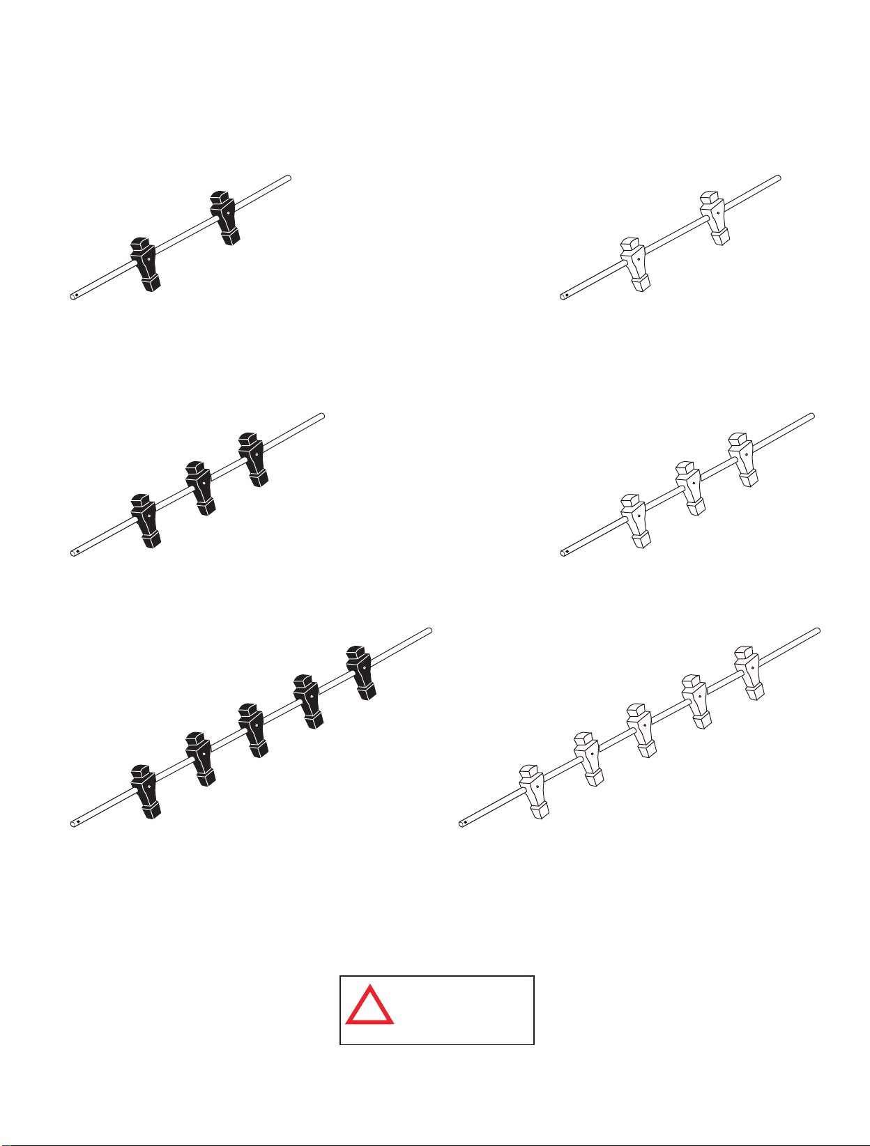
IDENTIFICADOR DE LAS BARRAS
( No a Escala)
R1 - Barra con 2 jugadores
Negros (1 pza.)
R2 - Barra con 3 jugadores
Negros (2 pzas.)
R4 - Barra con 2 jugadores
color Marfil (1 pza.)
R5 - Barra con 3 jugadores
color Marfil (2 pzas.)
R3 - Barra con 5 jugadores
Negros (1 pza.)
Todos los derechos reservados.
©
2016 Escalade Sports
ADVERTENCIA:
PELIGRO DE ASFIXIA
!
Piezas pequeñas.
No adecuadas para niños
menores de 3 años.
20
R6 - Barra con 5 jugadores
color Marfil (1 pza.)
Para Servicio al cliente llame1-888-996-2729
Page 21
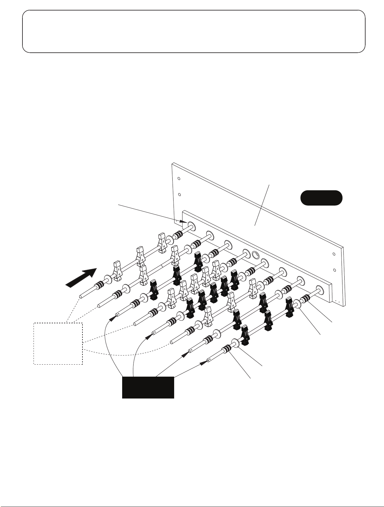
PARTES REQUERIDAS:
1 pza. - P1 Panel Lateral 1 pza. - R1 Barra con 2 jugadores (Negros) 1 pza. - R4 Barra con 2 jugadores (Marfil)
16 pzas. - P13 Rondana de Plástico 2 pzas. - R2 Barra con 3 jugadores (Negros) 2 pzas. - R5 Barra con 3 jugadores (Marfil)
16 pzas. - P14 Tope de la barra 1 pza. - R3 Barra con 5 jugadores (Negros) 1 pza. - R6 Barra con 5 jugadores (Marfil)
PASO 1:
Elija una superficie plana, nivelada y limpia para empezar a ensamblar su mesa de fútbol. Se recomienda construir
la mesa sobre la caja extendida para proteger las piezas durante el ensamblamiento.
Adjunte la Rondana de Plástico P13 y el Tope de la barra P14 a las barras como se muestra en la .
FIGURA 1
Coloque un Panel Lateral P1 BOCA ABAJO con el lado laminado hacia afuera como se muestra en FIGURA 1.
Alinear las barras como se muestra en la FIGURA 1.
Por favor, tenga en cuenta la ubicación del orificio que está cerca de un extremo de cada barra. Este es el
extremo del mango de la barra.
Habrá cuatro mangos en las barras en cada lado de la mesa. Es muy importante que se coloquen las barras
como se muestra a continuación para que la mesa quede ajustada correctamente cuando se voltee.
C1 Buje de la barra
P1
Nota: C1 Buje de la barras
ya están instalados en cada
FIGURA 1
Panel Lateral P1
R4, R5 y R6
El orificio/Mango
va en el otro
extremo de
estas barras
R5
R4
R2
R6
R1, R2 y R3
Orificio/Extremo
del Mango
R3
R5
R1
R2
P14
P13
P13
P14
Todos los derechos reservados.
©
2016 Escalade Sports
21
Para Servicio al cliente llame1-888-996-2729
Page 22
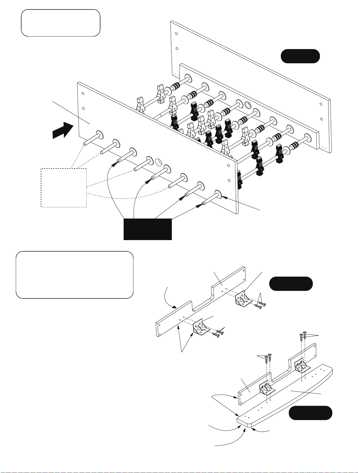
PARTES REQUERIDAS:
1 pza. - P1 Panel Lateral
PASO 2:
Una vez que se asegure de que las barras estén
colocadas correctamente, deslice el otro Panel
Lateral P1 en las barras como se muestra en la
FIGURA 2.
P1
R5
R4
R2
R4, R5 y R6
El orificio/Mango
va en el otro
extremo de
estas barras
R6
R3
R1, R2 y R3
Orificio/Extremo
del Mango
R5
R1
R2
FIGURA 2
C1 Buje de la barra
Nota: C1 Buje de la barras
ya están instalados en
cada
P1 Panel Lateral
PARTES REQUERIDAS:
16 pzas. - H4 Tornillo Phillips (Cabeza redonda)
2 pzas. - P5 Riel Superior
2 pzas. - P6 Tabla del Extremo
4 pzas. - P18 Soporte de Plástico
Laminado blanco
de este lado
PASO 3:
Coloque los dos Soportes de Plástico en el interior
de cada extremo de las Tablas P6 como se muestra y
únala usando los orificios guía ya pre-perforados con
H4 tornillos como se muestra en la FIGURA 3A.
Apriete los tornillos H4, pero no los sobre apriete ya
que se dañarían.
NOTA: Asegúrese que la orilla inferior de los P18
Soportes de Plástico coincidan con la orilla inferior de la
tabla.
Coloque este ensamblado al Riel Superior P5 usando
los orificios guía ya pre-perforados con H4 tornillos
como se muestra en la FIGURA 3B.
Apriete los tornillos, pero no los sobre apriete ya
que se dañarían H4 tornillos.
NOTA: Asegúrese que la orilla inferior de las Tablas del
Extremo P6 coincida con la orilla inferior del P5 Riel
Superior.
Repita el procedimiento para la segunda parte a
ensamblar.
Todos los derechos reservados.
©
2016 Escalade Sports
P18
P6
La orilla debe
coincidir para un
ensamblamiento
correcto
La orilla debe
coincidir para un
ensamblamiento
correcto
Laminado
Negro en el
lado de abajo
NOTA: Ver el PASO 4
para el ensamblado
correcto de
P5 y P6.
22
P18
FIGURA 3A
H4
P18
H4
H4
H4
P6
P5
FIGURA 3B
La esquina
redonda en
esta posición
Para Servicio al cliente llame1-888-996-2729
Page 23
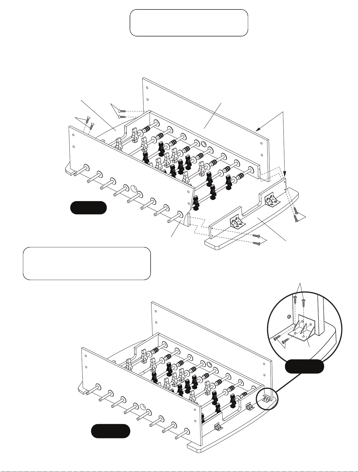
PARTES REQUERIDAS:
PASO 4:
8 pzas. - H3 Tornillo Phillips (cabeza plana)
Coloque los paneles P5/P6 ensamblados anteriormente en el PASO 3 al Panel Lateral P1 utilizando los orificios
guía pre-perforados con los Tornillos H3 como se muestra en la FIGURA 4. Apriete, pero no sobre apriete los
Tornillos H3.
NOTA IMPORTANTE: Los orificios están pre-perforados en ANGULO al propósito, permita y asegúrese
de que los tornillos H3 se inserten siguiendo los orificios pre-perforados.
NOTA IMPORTANTE
P5/P6
Asamblea
H3
H3
P1
Asegúrese de mantener
encuadrado este ensamblado
durante el ensamblamiento de
P5/P6.
FIGURA 4
PARTES REQUERIDAS:
16 pzas. - H4 Tornillo Phillips (Cabeza redonda)
4 pzas. - P18 Soporte de Plástico
PASO 5:
Instale un P18 Soporte de Plástico en el
interior de cada esquina de P1 Panel Lateral
usando los orificios guía ya pre-perforados y
tornillos H4 como se muestra en la FIGURA
.
5 y DETALLE A
Apriete los tornillos H4, pero no los sobre
apriete ya que se dañarían.
P1
H3
H3
P5/P6
Asamblea
H4
H4
P18
DETALLE A
Todos los derechos reservados.
©
2016 Escalade Sports
FIGURA 5
23
Para Servicio al cliente llame1-888-996-2729
Page 24
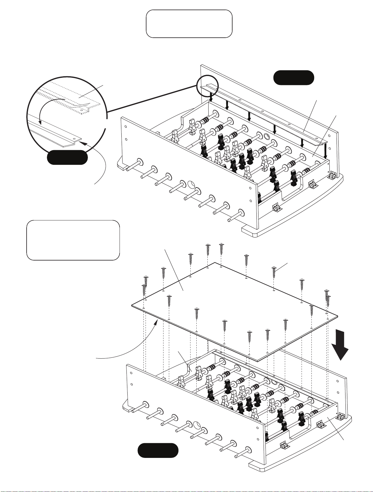
PARTES REQUERIDAS:
2 pzas. - P12 Borde de
PASO 6:
Despegue con cuidado las tiras protectoras de las 3 piezas de cinta adhesiva de la parte inferior de ambas
piezas P12. Voltéelos y cuidadosamente colocarlos a lo largo de Paneles Laterales P1 como se muestra en el
DETALLE B y FIGURA 6.
P12
Despegue y Voltear
DETALLE B
Superficie de juego
FIGURA 6
P12
P1
NOTA:
tira
adhesiva
de este
lado
.
PARTES REQUERIDAS:
18 pzas. - H5 Tornillo Phillips
(cabeza tipo arandela)
1 pza. - P4 Superficie de Juego
PASO 7:
Coloque la Superficie de Juego P4
al gabinete con diseño gráfico hacia
abajo. Alinear orificios en la
Superficie de Juego P4 con los
orificios en los Bordes P12 y únala
usando H5 tornillos como se
muestra en la FIGURA 7.
Apriete los tornillos, pero
sobre apriete ya que se dañarían
Diseño gráfico
hacia abajo
no los
P4
H5
.
P6
NOTA IMPORTANTE
P4 debe estar uniformemente
espaciadas sobre la parte superior
de ambos extremos de la Tabla del
Extremo P6- en cada extremo del
gabinete ensamblado..
P1 Paneles Laterales pueden estar
ligeramente curvados. Mantenga P1
Panel Lateral presionado firmemente
contra la superficie de juego P4 para el
ensamblamiento correcto.
Todos los tornillos deben estar
atornillados RECTOS Hacia abajo.
Todos los derechos reservados.
©
2016 Escalade Sports
FIGURA 7
24
P6
Para Servicio al cliente llame1-888-996-2729
Page 25
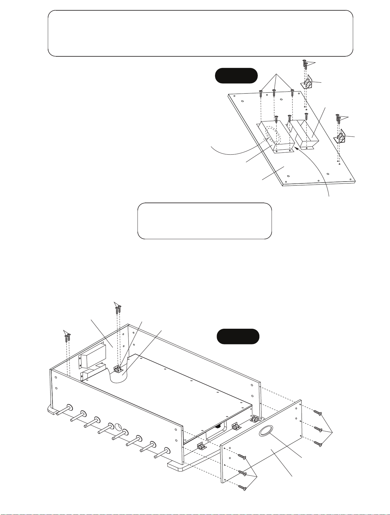
PARTES REQUERIDAS:
20 pzas. - H4 Tornillo Phillips (Cabeza redonda) 2 pzas. - P8 Porteria (Parte Superior)
4 pzas. - P18 Soporte de Plástico 2 pzas. - P2 Panel del Extremo
2 pzas. - P9 Porteria (Parte Inferior)
PASO 8:
Coloque los Soportes de Plástico P18 en la parte de
atrás del Panel del Extremo P2 usando los orificios guía
FIGURA 8
H4
H4
P18
ya pre-perforados con tornillos H4 como se muestra en
la FIGURA 8.
Apriete los tornillos, pero no los sobre apriete ya
que se dañarían.
NOTA: Asegúrese que la orilla inferior de los Soportes
de Plástico P18 coincida con la orilla inferior del panel.
Coloque P8 Porteria (Parte Superior) y P9 Porteria
NOTA:
Entrada de la bola
en P2 debe estar
en esta posición
P8
H4
P18
(Parte Inferior) en la parte de atrás del P2 Panel del
Extremo usando los orificios guía ya pre-perforados con
tornillos H4 como se muestra en la FIGURA 8.
Apriete los tornillos, pero no los sobre apriete ya
que se dañarían.
Repita el procedimiento para la
segunda parte a ensamblar.
PARTES REQUERIDAS:
8 pzas. - H4 Tornillo Phillips (Cabeza redonda)
12 pzas. - H7 Tornillo Phillips (cabeza plana)
P9
P2
NOTA:
Entrada de la caja de la
portería P9 debe estar en
esta posición.
PASO 9:
Coloque lo que anteriormente se ensambló en el Paso 8 en el extremo del gabinete de la mesa usando
los orificios guía pre-perforados con los tornillos H7 como se muestra en la
FIGURA 9. Apriete los
tornillos, pero no los sobre apriete ya que se dañarían.
Instale los Tornillos H4 en los soportes de Plástico P18 previamente instalados como se muestra en la
FIGURA 9. Apriete los tornillos, pero no los sobre apriete ya que se dañarían.
H4
Asamblea del
8
Paso
H4
P18
P5
FIGURA 9
H7
C2
Todos los derechos reservados.
©
2016 Escalade Sports
25
H7
Asamblea del
8
Paso
Para Servicio al cliente llame1-888-996-2729
Page 26
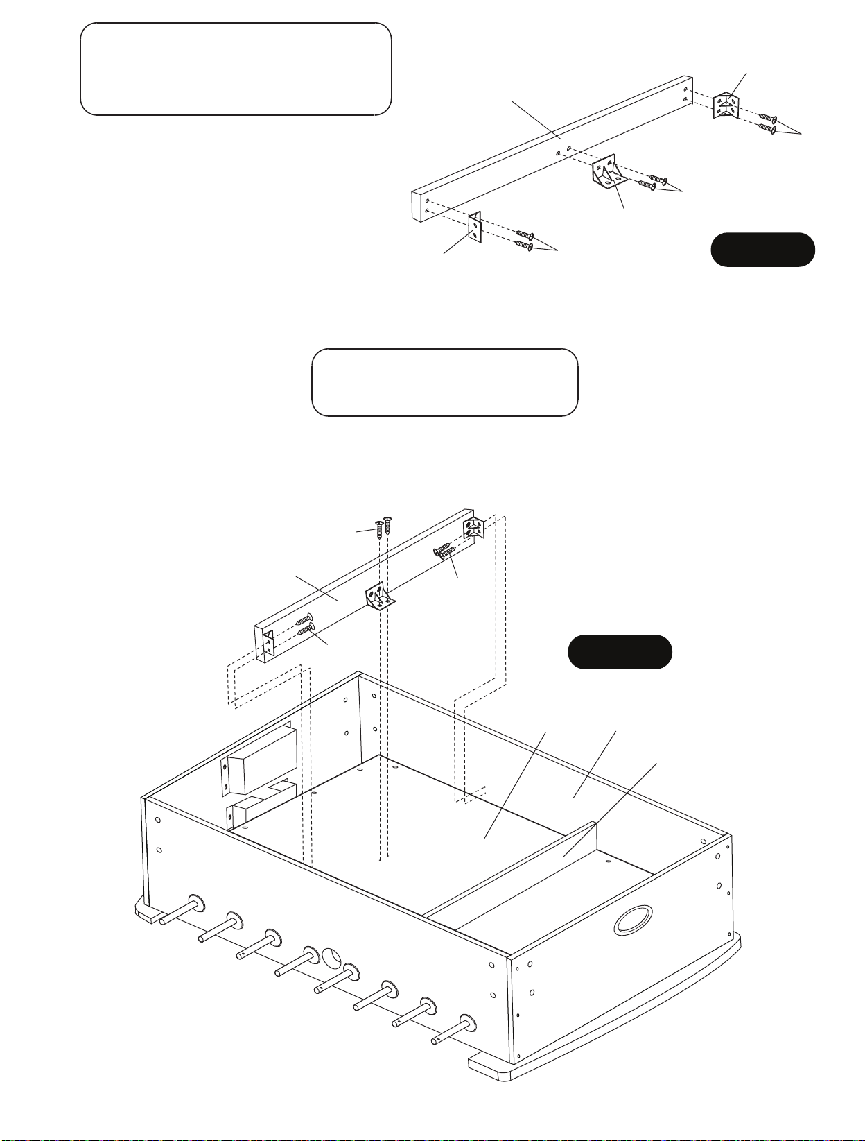
PARTES REQUERIDAS:
12 pzas. - H4 Tornillo Phillips (Cabeza redonda)
2 pzas. - P7 Soporte de la Superficie de Juego
6 pzas. - P18 Soporte de Plástico
P18
P7
PASO 10:
Coloque Soporte de Plástico P18 en los Soportes de
la Superficie de Juego P7 usando los orificios guía
ya pre-perforados con tornillos H4 como se muestra
en la FIGURA 10.
Apriete los tornillos, pero no los sobre apriete ya
que se dañarían.
P18
P18
H4
H4
FIGURA 10
NOTA: Asegúrese que la orilla inferior de los
Soportes de Plástico P18 coincidan con la orilla del
Soporte de la Superficie de Juego P7.
PARTES REQUERIDAS:
12 pzas. - H4 Tornillo Phillips
(Cabeza redonda)
PASO 11:
Coloque lo que anteriormente se ensamblo en el PASO 10 en partes P3 Superficie de Juego y P1 Paneles
Laterales usando los orificios guía ya pre-perforados con los tornillos H4 como se muestra en la FIGURA 11.
Apriete los tornillos, pero no los sobre apriete ya que se dañarían.
NOTA:
Asegúrese de que los soportes de plástico están frente a frente para un ensamblaje correcto.
H4
H4
Asamblea del
Paso 10
H4
H4
P3
FIGURA 11
P1
Asamblea del
Paso 10
Todos los derechos reservados.
©
2016 Escalade Sports
26
Para Servicio al cliente llame1-888-996-2729
Page 27
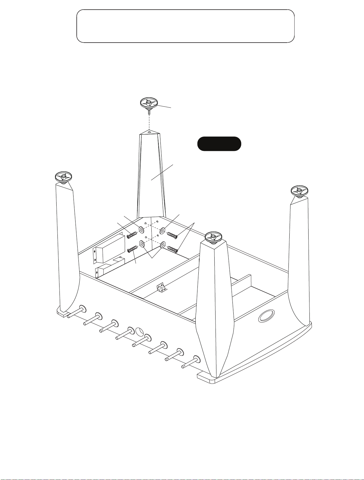
PARTES REQUERIDAS:
16 pzas. - H1 Tornillo Allen 4 pzas. - P3 Pata 1 pza. - T1 Llave Allen
16 pzas. - H2 Rondana 4 pzas. - P11 Nivelador de las patas
PASO 12:
Coloque Patas P3 usando los Tornillo Allen H1 y Rondanas H2 como se muestra en
la FIGURA 12.
Use la Llave Allen T1 para apretar todos los tornillos. Coloque cada Nivelador P11 a
cada P3 Pata como se muestra en la FIGURA 12.
P11
FIGURA 12
P3
H1
H2
H2
H1
H2
H1
Todos los derechos reservados.
©
2016 Escalade Sports
27
Para Servicio al cliente llame1-888-996-2729
Page 28
ADVERTENCIA
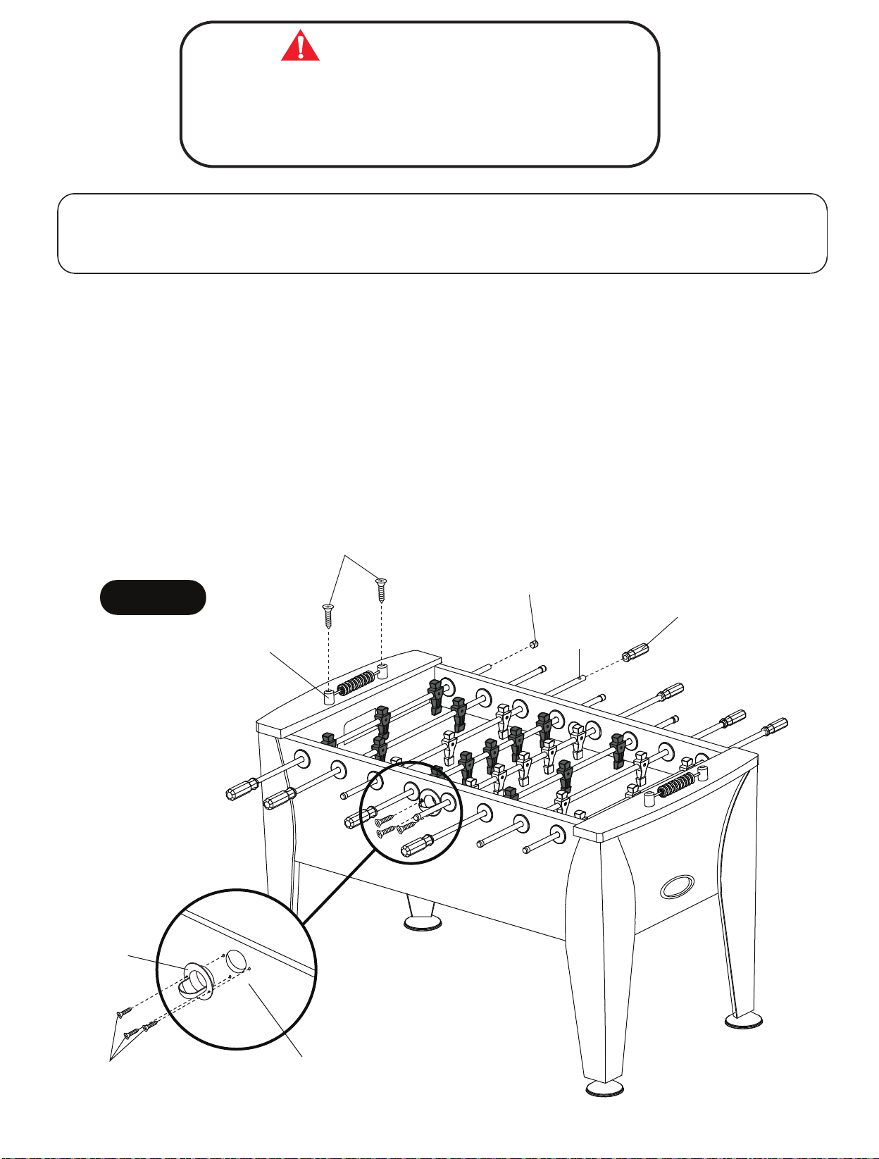
ESTE PASO REQUIERE DE DOS O MAS ADULTOS.
CON MUCHO CUIDADO VOLTEE LA MESA HASTA QUE LAS
PATAS DE LA MESA ESTÉN SOBRE EL PISO.
TENGA CUIDADO LA MESA ESTÁ MUY PESADA.
PARTES REQUERIDAS:
6 pzas. - H6 Tornillo Phillips (cabeza plana) 2 pzas. - P10 Marcador 8 pzas. - P16 Mango de la barra
4 pzas. - H8 Zinc-Tornillo Phillips (cabeza plana) 8 pzas. - P15 Tapón para la barra 2 pzas. - P17 Entrada de pelotas
PASO 13:
Coloque los marcadores P10 sobre de los rieles superiores P5 usando tornillos H8 como se muestra en la FIGURA
13. Apriete los tornillos, pero no los sobre apriete ya que se dañarían.
Coloque los Tapones P15 a las barras como se muestra en la FIGURA 13.
Deslice el Mango P16 en cada barra con el pequeño orificio, como se muestra en la FIGURA 13.
NOTA IMPORTANTE Agregue una pequeña cantidad de jabón líquido dentro de cada Mango P16 que les
permitirá deslizarse más fácilmente.
Coloque las Entradas de Pelotas P17a los Paneles Laterales P1 usando tornillos H6 como se muestra en la FIGURA
13.
Apriete los tornillos, pero no los sobre apriete ya que se dañarían.
H8
FIGURA 13
P15
Nota:
Small
Hole
P16
P10
P17
H6
Todos los derechos reservados.
©
2016 Escalade Sports
P1
28
Para Servicio al cliente llame1-888-996-2729
Page 29
Felicidades! Ahora ya ha terminado de ensamblar su mesa. Por favor, Siga las instrucciones del uso y el
cuidado de su mesa abajo mencionadas, para garantizar muchos años sin problemas el juego de su mesa.
CUIDADO Y USO DE SU MESA
1.
Use spray abrillantador con un trapo limpio para limpiar las barras y se deslicen
mas fácil en los bujes de las barras.
2.
Use spray abrillantador para limpiar todas las superficies exteriores de su mesa.de muebles
3.
Utilice un nivel de carpintero para nivelar la mesa con los niveladores de las patas.
Este producto está diseñado para su uso en INTERIORES exclusivamente.
4.
NO sentarse, subirse, apoyarse sobre la mesa.
5.
6.
NO arrastre la mesa para moverla. Si lo hace se dañará las patas.
NO ponga bebidas sobre la mesa.
7.
LISTA DE PARTES PARA EL MODELO # G01342W
de muebles
Clave N.º de Parte
H1
H2
H3
H4
H5
H6
H7
H8
T1
A1
P1
P2
P3
P4
P5
P6
P7
P8
P9
P10
P11
P12
P13
P14
P15
P16
P17
P18
C1
C2
C3
C4
C5
C6
C7
C8
C9
K1
M1
01342WJH1
01342WJH2
01342WJH3
01342WJH4
01342WJH5
01342WJH6
01342WJH7
01342WJH8
01342WJT1
01342WJA1
01342WJP1
01342WJP2
01342WJP3
01342WJP4
01342WJP5
01342WJP6
01342WJP7
01342WJP8
01342WJP9
01342WJP10
01342WJP11
01342WJP12
01342WJP13
01342WJP14
01342WJP15
01342WJP16
01342WJP17
01342WJP18
01342WJC1
01342WJC2
01342WJC3
01342WJC4
01342WJC5
01342WJC6
01342WJC7
01342WJC8
01342WJC9
01342WJK1
01342WJM1
Descripción
6mm x 22mm Tornillo Allen
6mm x 19mm Rondana
3mm x 28mm Tornillo Phillips (cabeza plana)
4mm x 12mm Tornillo Phillips (Cabeza redonda)
3mm x 28mm Tornillo Phillips (cabeza tipo arandela)
4mm x 12mm Tornillo Phillips (cabeza plana)
4mm x 51mm Tornillo Phillips (cabeza plana)
4mm x 51mm Zinc - Tornillo Phillips (cabeza plana)
Llave Allen
Balón de Fútbol
Panel Lateral
Panel del Extremo
Pata
Superficie de Juego
Riel Superior
Tabla del Extremo
Soporte de la Superficie de Juego
Porteria (Parte Superior)
Porteria (Parte Inferior)
Marcador
Nivelador de las patas
Borde de Superficie de juego
Rondana de Plástico
Tope de la barra
Tapón para la barra
Mango de la barra
Entrada de pelotas
Soporte de Plástico
Buje de la barra
Borde de Retorno para Balón
Jugador Negro
Jugador Marfil
Barra de 2 Jugadores
Barra de 3 Jugadores
Barra de 5 Jugadores
4mm x 21mm Tornillo Phillips
4mm Tuerca de Seguridad
Conjunto de Tornillos y Tuercas
Manual
Cant.
16
16
8
84
18
6
12
4
1
4
2
2
4
1
2
2
2
2
2
2
4
2
16
16
8
8
2
18
16
2
13
13
2
4
2
26
26
1
1
Todos los derechos reservados.
©
2016 Escalade Sports
29
Para Servicio al cliente llame1-888-996-2729
Page 30
Todos los derechos reservados.
©
2016 Escalade Sports
30
Para Servicio al cliente llame1-888-996-2729
 Loading...