

Page 1

y t i l a u q t s e h g i h e h t f o e r a s t c u d o r p r u o t a h t e r u s n e o t e v i r t s e W
e r f d n a
f i , r e v e w o H . s t r a p g n i s s i m r o s t c e f e d g n i r u t c a f u n a m f o e
, t c u d o r p w e n r u o y h t i w s m e l b o r p y n a e v a h u o y
E R O T S E H T O T T I N R U T E R T O N O D ,
: @ e e r f l l o t s u t c a t n o c e s a e l p
888-996-2729 - 1
1 3 5 3 - 3 7 8 - 6 6 8 - 1 : X A F
m o c . s t r o p s e d a l a c s e @ gameroom
: o t e t i r w r O
s t r o p S e d a l a c s E
t n e m t r a p e D e c i v r e S r e m o t s u C
9 8 8 x o B . O . P
6 0 7 7 4 N I , e l l i v s n a v E
. s t r a p t u o b a g n i r i u q n i n e h w dat e code r u o y e v a h e s a e l P
date code (if , r e b m u n l e d o m r u o y e d i v o r p e s a e l p s t r o p S e d a l a c s E g n i t c a t n o c n e h W
e r a g n i t s e u q e r f i r e b m u n t r a p d n a , ) e l b a c i l p p a
. l a u n a m s r e n w o s i h t n i d n a , g n i g a k c a p , t c u d o r p e h t n o d e t a c o l
G01889W
r e b m u N l e d o M r u o Y
Dat e Code:
Purchase Date:
PLEASE RETAIN THIS INSTRUCTION MANUAL FOR FUTURE REFERENCE
All Rights Reserved
2 - G01889W - - WJ
888-996-2729 - 1 l l a C e c i v r e S r e m o t s u C r o F 1 s t r o p S e d a l a c s E 120 2 ©
e r a s r e b m u n e s e h T . t r a p t n e m e c a l p
Page 2
IMPORTANT! READ EACH STEP
IN THIS MANUAL BEFORE YOU
BEGIN THE ASSEMBLY.
TWO
ADULTS ARE REQUIRED TO ASSEMBLE
THIS ATOMIC GLADIATOR SOCCER TABLE
Tools Required:
T1 - Allen Wrench (Included)
Phillips Screwdriver
Furniture Polish and Cloth
Assembly Tips
Make sure you understand the following tips before you begin to assemble your soccer table.
1. Start all bolts by hand before tightening.
2. Some drawings or images in this manual may not look exactly like your product. Please
read and understand the text before starting each assembly step.
ATTENTION:
READ AND FOLLOW ALL ASSEMBLY, OPERATION, AND
SAFETY INSTRUCTIONS CAREFULLY. AT LEAST TWO
ADULTS ARE NEEDED TO PUT THIS SOCCER TABLE
TOGETHER.
All Rights Reserved.
©
2012 Escalade Sports
2
For Customer Service Call 1-888-996-2729
Page 3
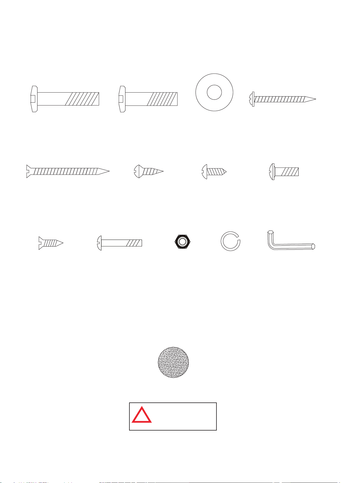
HARDWARE IDENTIFIER
( To Scale)
H1 - 5/16” x 1-1/2”
Allen Head Bolt
(8 pcs)
H5 - #4 x 2”
Phillips Flat
Head Screw
(6 pcs)
H9 - #3 x 15mm
Phillips Flat Head
Screw (8 pcs)
H2 - 5/16” x 1-1/4”
Allen Head Bolt
(16 pcs)
H6 - #4 x 5/8”
Phillips Round
Head Screw
(6 pcs)
H10 - #4 x 1”
Phillips Round Head
Bolt (26 pcs)
H11 - #4
Lock Nut
(26 pcs)
H3 - 5/16”
Flat Washer
(24 pcs)
H7 - #4 x 1/2”
Phillips Round
Head Screw
(20 pcs)
H12 - 5/16”
Lock Washer
(24 pcs)
H4 - #3.5 x 1-1/2”
Phillips Washer
Head Screw
(12 pcs)
H8 - 3/16” x 5/8”
Phillips Round
Head Bolt
(8 pcs)
(Not to Scale)
T1 - Allen Wrench
(1 pc)
All Rights Reserved.
©
2012 Escalade Sports
ACCESSORIES IDENTIFIER
( Not to Scale)
A1- Soccer Ball (4 pcs)
WARNING:
CHOKING HAZARD
!
Small parts.
Not for children under 3 yrs.
3
For Customer Service Call 1-888-996-2729
Page 4
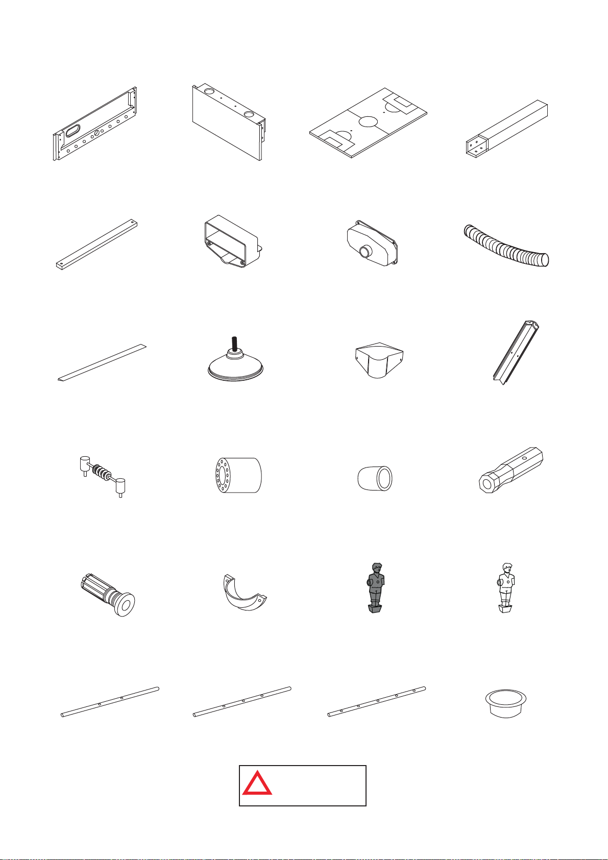
PARTS IDENTIFIER
( Not to Scale)
P1 - Side Apron
(2 pcs)
P5 - Playfield Support
Brace (3 pcs)
P9 - Playfield Trim
(2 pcs)
P2 - End Apron
(2 pcs)
P6 - Goal Box
(2 pcs)
P10 - Leg Leveler
(4 pcs)
P3 - Playfield (1 pc)
P7 - Ball Catcher
(2 pcs)
P11 - Corner Cap
(4 pcs)
P4 - Leg
(4 pcs)
P8 - Ball Return
Tube (2 pcs)
P12 - Corner Post
(4 pcs)
P13 - Scorer (2 pcs)
P17 - Rod Bushing
(16 pcs)
P21 - 2 Player Rod
(2 pcs)
All Rights Reserved.
©
2012 Escalade Sports
P14 - Rod Bumper
(16 pcs)
P18 - Ball Entry
Cup (2 pcs)
P22 - 3 Player Rod
(4 pcs)
WARNING:
CHOKING HAZARD
!
Small parts.
Not for children under 3 yrs.
P15 - Rod End
Cap (8 pcs)
P19 - Red Shirt /
Black Shorts
Player (13 pcs)
P23 - 5 Player Rod
(2 pcs)
4
P16 - Rod Handle
(8 pcs)
P20 - Black Shirt /
Yellow Shorts
Player (13 pcs)
P24 - Cup Holder
(4 pcs)
For Customer Service Call 1-888-996-2729
Page 5
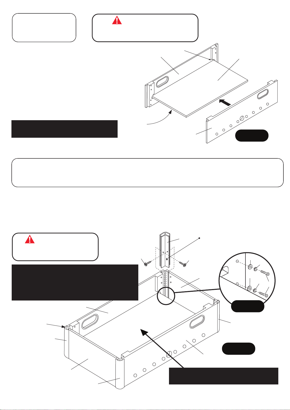
PARTS REQUIRED:
2 pcs - P1 Side Apron
1 pc - P3 Playfield
ATTENTION:
THIS STEP REQUIRES TWO OR MORE ADULTS.
VERY CAREFULLY SET P3 PLAYFIELD INTO THE GROOVES
IN P1 SIDE APRON.
STEP 1:
Find a clean, level place to begin the assembly of your
P1
Groove
P3
soccer table. We recommend building the table on the
box top to protect the parts during assembly.
It is very important to assemble table on a level and
flat surface. This will keep the end aprons and side
aprons “FLUSH” on the top and bottom edges.
Set P3 Playfield into the grooves in P1 Side
Apron as shown in FIGURE 1.
IMPORTANT NOTE: Be sure playfield is
centered before installing any H4 Screws.
PARTS REQUIRED:
8 pcs - H1 Allen Head Bolt 8 pcs - H7 Phillips Round Head Screw 2 pcs - P2 End Apron 1 pc - T1 Allen
8 pcs - H3 Flat Washer 8 pcs - H12 Lock Washer 4 pcs - P12 Corner Post Wrench
NOTE:
Graphic on this side.
P1
FIGURE 1
STEP 2:
Attach P2 End Aprons onto P1 Side Apron using H1 Allen Head Bolts with H12 Lock Washers and H3 Flat Washers
as shown in DETAIL A. Do not tighten H1 Bolts on this time.
Slide P12 Corner Posts on the each end of P1 Side Apron and P2 End Apron. Center P3 Playfield and tighten H1
Bolts using T1 Allen Wrench.
Use H7 Screws to secure P12 Corner Post as shown in FIGURE 2. Tighten, but do not strip out H7 Screws.
ATTENTION:
THIS STEP REQUIRES TWO OR MORE ADULTS.
VERY CAREFULLY ATTACH P12 CORNER POST
VERY IMPORTANT! DO NOT TIGHTEN H1 BOLTS AT THIS TIME.
THE P12 CORNER POSTS MUST BE INSTALLED BEFORE
TIGHTENING THE H1 BOLTS. INSTALLATION OF THE P12
CORNER POSTS WILL SQUARE UP THE SIDE AND END APRONS
FOR CORRECT ASSEMBLY.
TIGHTEN THE H1 BOLTS ONLY AFTER THE P12 CORNER POSTS
ARE CORRECTLY INSTALLED.
NOTE: P12 Corner Post
should be flush with
bottom of P1 Side and
P2 End aprons.
ONTO EACH P1 & P2 APRON.
P1
H7
P12
H7
NOTE: Install P12 Corner Posts
with arrow pointing down.
H3
H12
P2
H3
H12
DETAIL A
P12
H1
P12
All Rights Reserved.
©
2012 Escalade Sports
P2
P12
FIGURE 2
P1
IMPORTANT NOTE: Center P3 Playfield
before tightening H1 Bolts.
5
For Customer Service Call 1-888-996-2729
Page 6
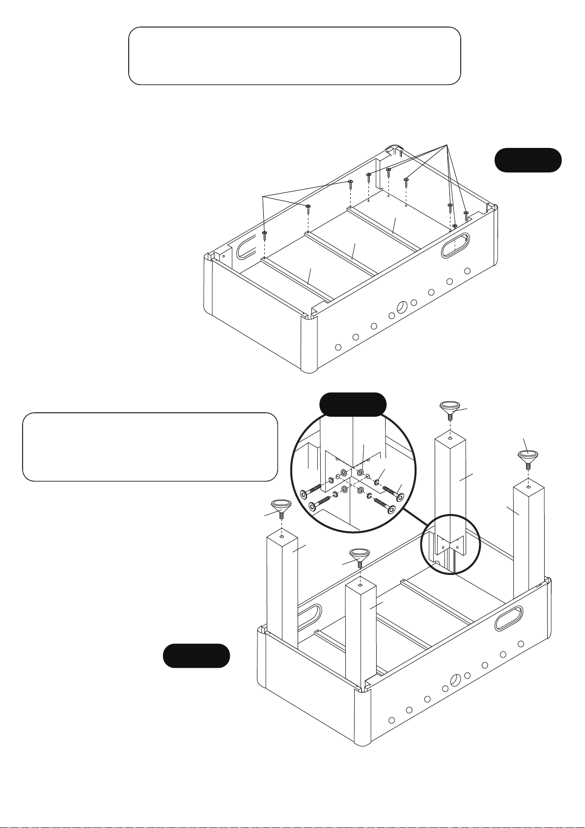
PARTS REQUIRED:
12 pcs - H4 Phillips Washer Head Screw 3 pcs - P5 Playfield
6 pcs - H5 Phillips Flat Head Screw Support Brace
STEP 3:
Center and attach P3 Playfield in the cabinet using pre-drilled pilot holes with H4 Screws as shown in FIGURE 3.
Place each P5 Playfield Support Brace and attach using pre-drilled pilot holes with H5 Screws as shown in
FIGURE 3.
H4
Important Note: Please be sure to install H4 screws and H5 screws
exactly as per FIGURE 3. Screws must be screwed straight down.
H5
IMPORTANT NOTE: Center P3
Playfield before installing H4 and
H5 Screws.
If P3 playfield is not centered,
you may need to loosen H1
Bolts ( in Step 2 ) to correctly
P5
center the P3 Playfield
- Retighten H1 Bolts once P3
Playfield is correctly centered.
PARTS REQUIRED:
16 pcs - H2 Allen Head Bolt 4 pcs - P4 Leg
16 pcs - H3 Flat Washer 4 pcs - P10 Leg Leveler
16 pcs - H12 Lock Washer 1 pc - T1 Allen Wrench
P5
DETAIL B
H3
H12
P5
H2
FIGURE 3
P10
P10
P4
STEP 4:
Attach P4 Legs using H2 Allen Head
Bolts with H12 Lock Washers and H3 Flat
Washers as shown in FIGURE 4 & DETAIL B.
Use T1 Allen Wrench to tighten H1 Bolts.
Thread P10 Leg Levelers onto each P4 Leg
as shown in FIGURE 4.
FIGURE 4
All Rights Reserved.
©
2012 Escalade Sports
P10
P4
P4
P10
P4
6
For Customer Service Call 1-888-996-2729
Page 7
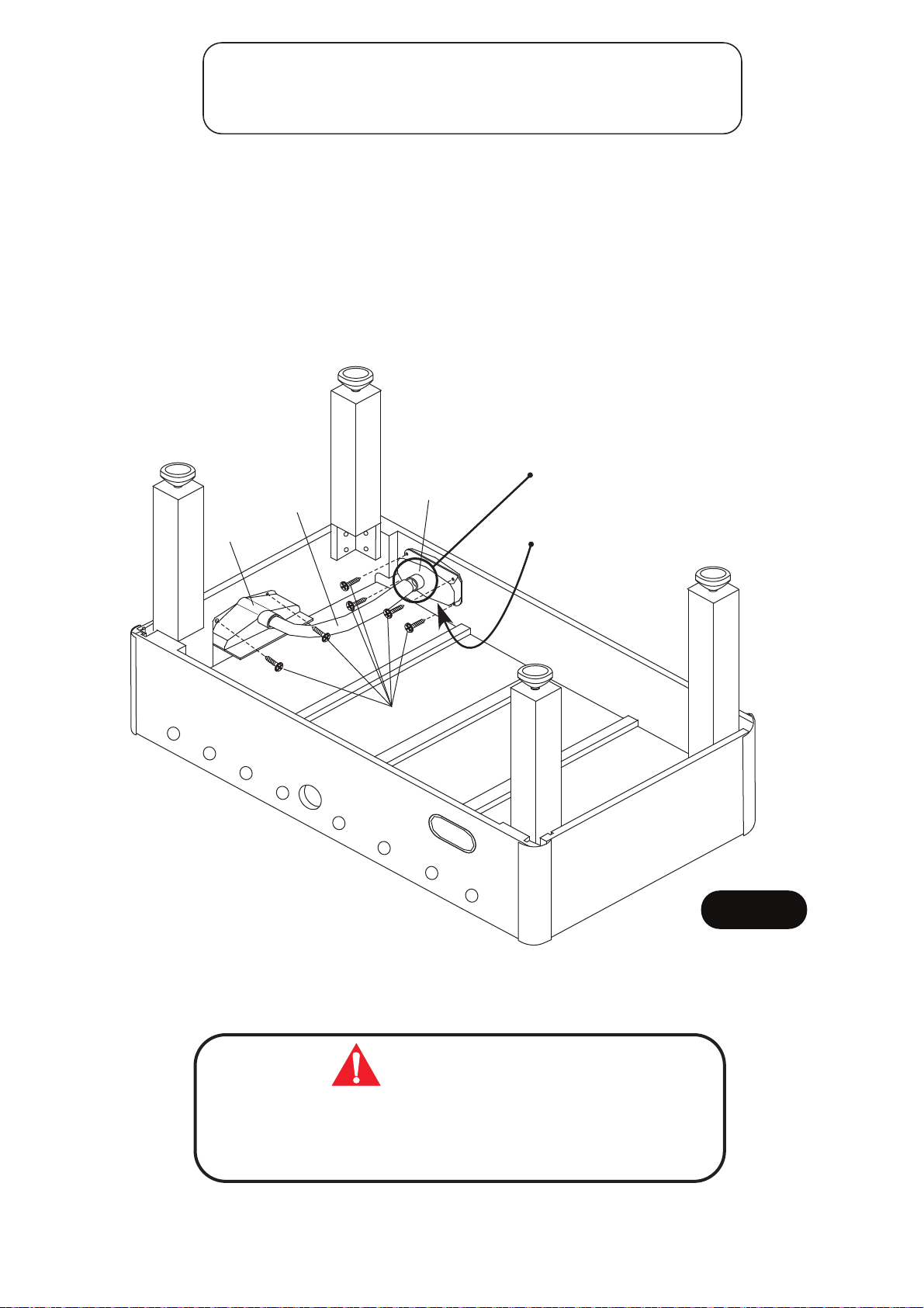
PARTS REQUIRED:
12 pcs - H7 Phillips Round Head Screw 2 pcs - P7 Ball Catcher
2 pcs - P6 Goal Box 2 pcs - P8 Ball Return Tube
STEP 5:
Center P6 Goal Box over the opening in the end panel and attach using pre-drilled pilot holes with H7 Screws as
shown in FIGURE 5.
Center P7 Ball Catcher over the opening in the side panel and attach using pre-drilled pilot holes with H7 Screws
as shown in FIGURE 5.
Make sure the round opening for P8 Ball Return Tube is towards the floor (when table is turned upright).
Repeat for both ends of the table.
Attach P8 Ball Return Tubes between P6 Goal Box and P7 Ball Catcher as shown in FIGURE 5.
NOTE: Make sure the round opening
P8
P7
for the ball return tube is towards the
floor (when table is turned upright)
P6
NOTE: Make sure the
opening is on this side.
H7
FIGURE 5
All Rights Reserved.
©
2012 Escalade Sports
CAUTION:
THIS STEP REQUIRES FOUR OR MORE ADULTS.
VERY CAREFULLY TURN THE TABLE OVER AND SET IT ON
ITS LEGS. BE CAREFUL. THE TABLE IS VERY HEAVY.
7
For Customer Service Call 1-888-996-2729
Page 8
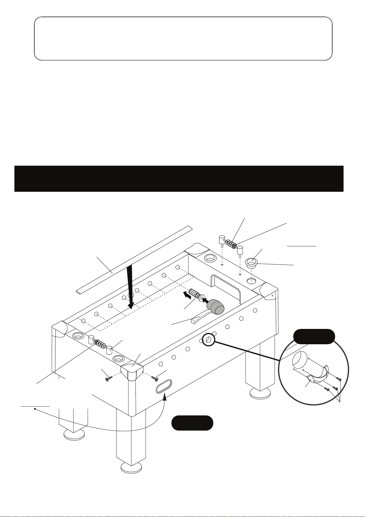
PARTS REQUIRED:
6 pcs - H6 Phillips Round Head Screw 4 pcs - P11 Corner Cap 2 pcs - P18 Ball Entry Cup
8 pcs - H9 Phillips Flat Head Screw 2 pcs - P13 Scorer 4 pcs - P24 Cup Holder
2 pcs - P9 Playfield Trim 16 pcs - P17 Rod Bushing
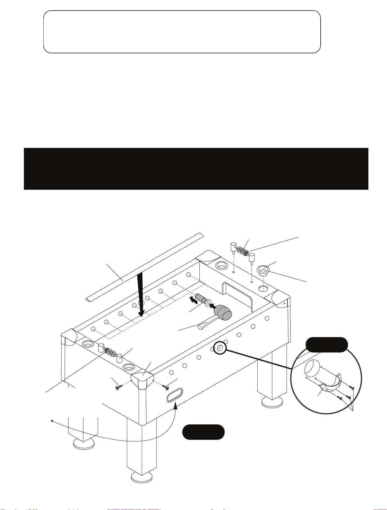
STEP 6:
Peel the adhesive strip protective coating off the underside of P9 Playfield Trims, then very carefully place them
along P3 Playfield as shown in FIGURE 6.
Carefully peel paper protective coating from adhesive strips from the back of P11 Corner Caps to reveal adhesive
strips. Attach P11 Corner Caps using H9 Screws as shown in FIGURE 6.
Tighten, but do not strip out H9 Screws.
Attach P13 Scorers onto the top of P2 End Apron as shown in FIGURE 6.
Insert P17 Rod Bushings onto both P1 Side Aprons as shown in FIGURE 6.
Please make sure to insert P17 Rod Bushings from the inner side of P1 Side Apron for correct assembly.
IMPORTANT NOTE: P17 Rod Bushings may require the use of a rubber hammer for installation into side apron.
With a rubber hammer, lightly tap bushing squarely into place. DO NOT USE STEEL HAMMER!
If a rubber hammer is not available, place a piece of wood squarely on bushing and lightly tap into place.
Attach P18 Ball Entry Cups using H6 Screws as shown in DETAIL C.
Tighten, but do not strip out H6 Screws.
Carefully - Tap P24 Cup Holders down into P2 End
Aprons as shown in FIGURE 6.
P9
P17
Rubber
Hammer
P13
P11
H9
H9
P13
P24
Note:
Red Bead scorer should
be on opposite side of
Ball Return.
Note:
Carefully tap P24
Cup Holders down.
DETAIL C
Note:
Red Bead scorer should
be on opposite side of
Ball Return.
All Rights Reserved.
©
2012 Escalade Sports
FIGURE 6
8
P18
H6
For Customer Service Call 1-888-996-2729
Page 9
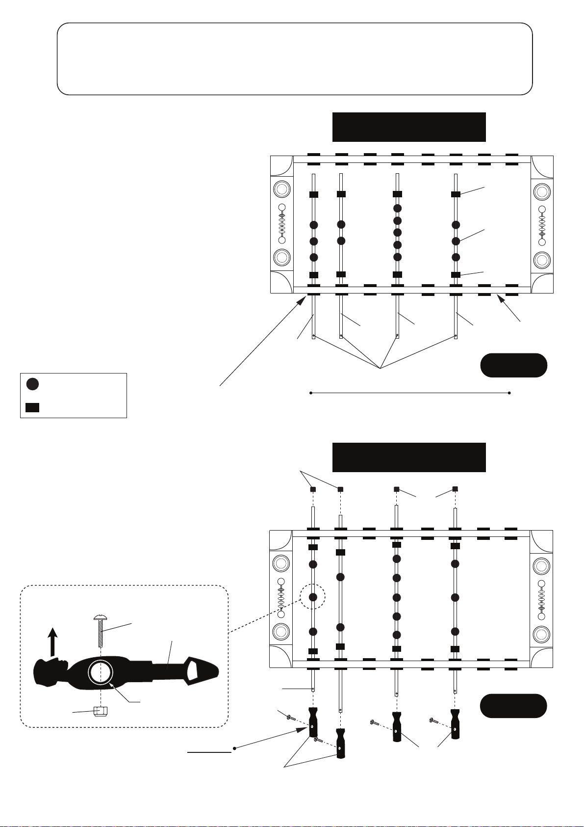
PARTS REQUIRED:
4 pcs - H8 Phillips Round Head Bolt 1 pc - P21 2 Player Rod 8 pcs - P14 Rod Bumper
13 pcs - H10 Phillips Round Head Bolt 2 pcs - P22 3 Player Rod 4 pcs - P15 Rod End Cup
13 pcs - H11 Lock Nut 1 pc - P23 5 Player Rod 4 pcs - P16 Rod Handle
13 pcs - P19 Red Shirt / Black Shorts Player
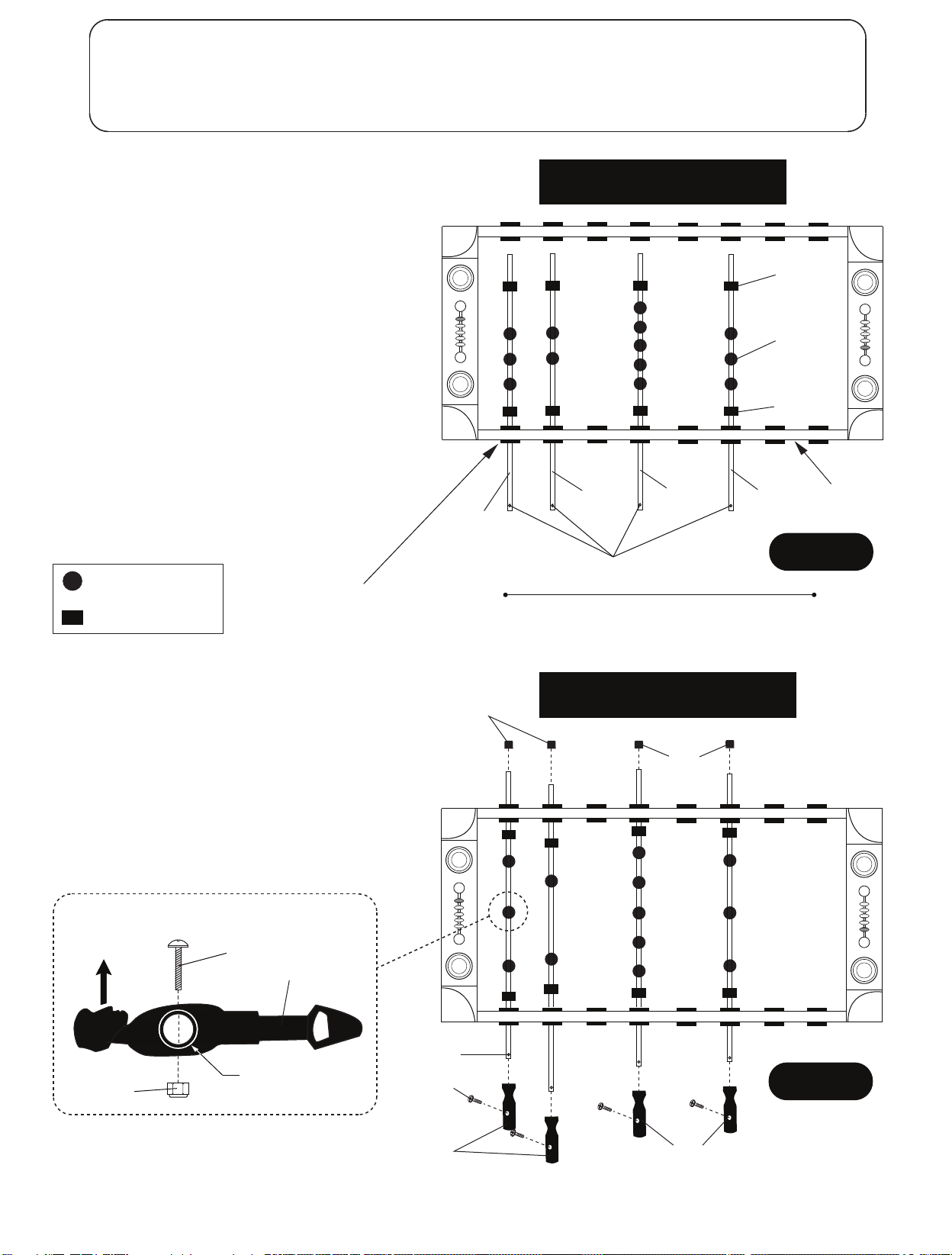
STEP 7:
Slide P22 3 Player Rods, P23 5 Player Rod and
P21 2 Player Rod through P17 Rod Bushings of
one P1 Side Apron as shown in FIGURE 7.
IMPORTANT NOTE: Please note the location
of the hole that is near one end of each rod.
This is the handle end of the rod.
Place one P14 Rod Bumper on each rod as
shown in FIGURE 7.
Place P19 Red Shirt / Black Shorts Players on
each rod as shown in FIGURE 7.
IMPORTANT NOTE: The goalie should be
at your left and your team (player face)
facing to the right.
Looking ahead to Page 10 FIGURE 10 - will
help you with correct player and rod handle
assembly onto rods.
Place one P14 Rod Bumper on each rod as
shown in FIGURE 7.
= P19 Red Shirt /
Black Shorts Player
= P14 Rod Bumper
P17 Rod
Bushing
P22
3 Player Rod
LEFT
OVERHEAD VIEW
LOOKING DOWN ONTO TABLE
P21
2 Player Rod
P23
5 Player Rod
P22
3 Player Rod
Hole / Handle End
P14
P19
P14
P1
Side Apron
FIGURE 7
RIGHT
STEP 8:
Align P19 Red Shirt / Black Shorts Player to each
player hole and attach using H10 Bolts with H11
Lock Nut as shown in FIGURE 8 and DETAIL A.
Attach P15 Rod End Caps to the rods as shown in
FIGURE 8.
Slide P16 Rod Handle onto each rod end with the
small hole as shown in FIGURE 8.
Attach P16 Rod Handle using H8 Bolts as shown
in FIGURE 8.
DETAIL A
Soccerman
facing up
H11
H10
P19
Rod
NOTE:
Small Hole
H8
P15
Rod End Cap
OVERHEAD VIEW
LOOKING DOWN ONTO TABLE
P15
Rod End Cap
FIGURE 8
IMPORTANT NOTE: Soccerman should be in vertical
position while attaching P16 Handles with thumb slot
facing up.
All Rights Reserved.
©
2012 Escalade Sports
P16
Rod Handle
P16
Rod Handle
9
For Customer Service Call 1-888-996-2729
Page 10
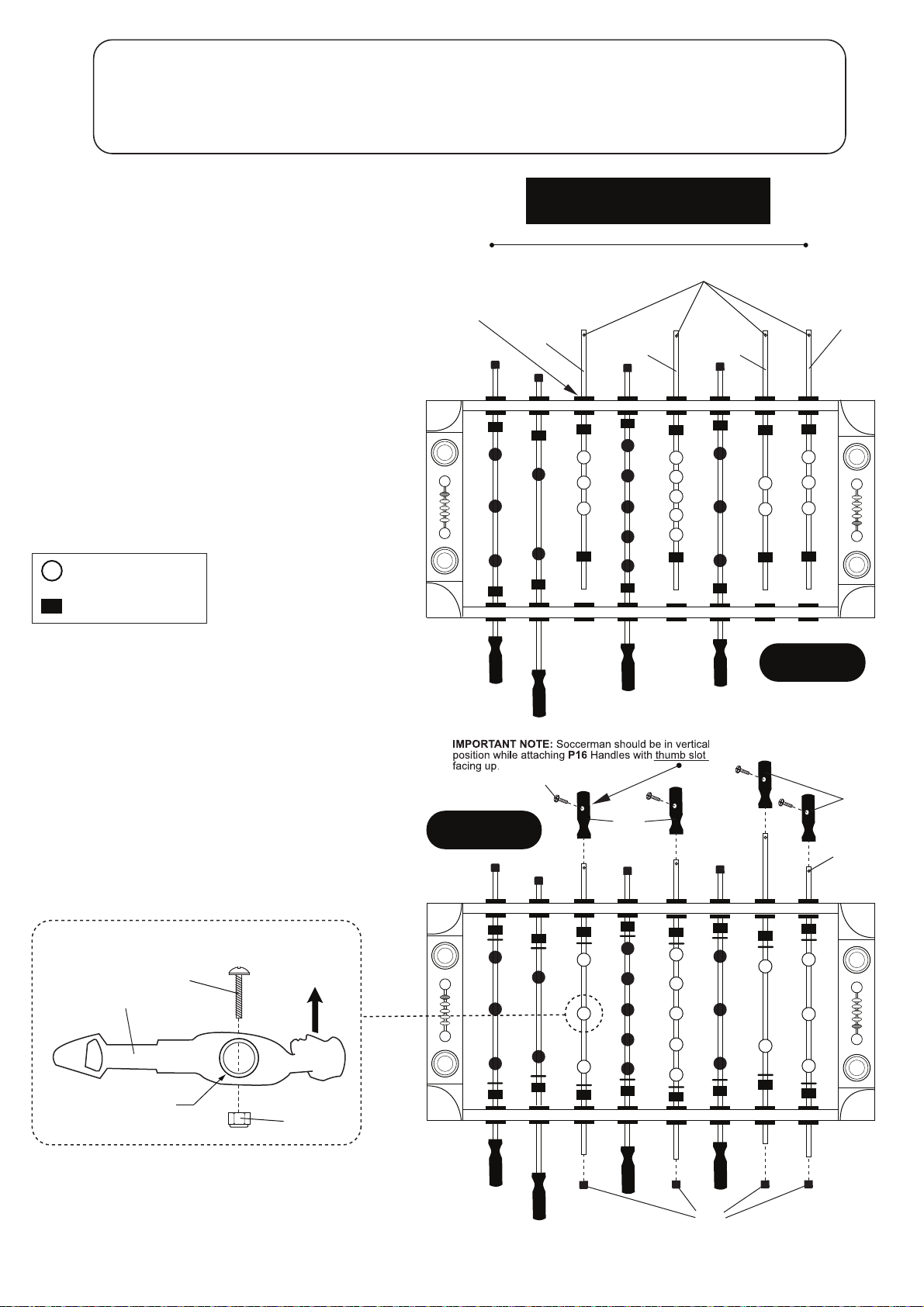
PARTS REQUIRED:
4 pcs - H8 Phillips Round Head Bolt 1 pc - P21 2 Player Rod 8 pcs - P14 Rod Bumper
13 pcs - H10 Phillips Round Head Bolt 2 pcs - P22 3 Player Rod 4 pcs - P15 Rod End Cup
13 pcs - H11 Lock Nut 1 pc - P23 5 Player Rod 4 pcs - P16 Rod Handle
13 pcs - P20 Black Shirt / Yellow Shorts Player
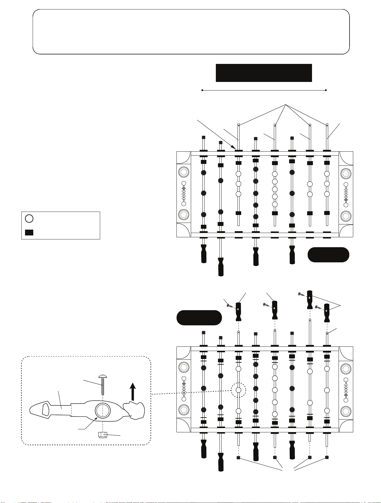
STEP 9:
Slide P22 3 Player Rods, P23 5 Player Rod and
P21 2 Player Rod through P17 Rod Bushings of
one P1 Side Apron as shown in FIGURE 9.
IMPORTANT NOTE: Please note the location
of the hole that is near one end of each rod.
This is the handle end of the rod.
Place one P14 Rod Bumper on each rod as
shown in FIGURE 9.
Place P20 Black Shirt / Yellow Shorts Players on
each rod as shown in FIGURE 9.
IMPORTANT NOTE: The goalie should be
at your left and your team (player face)
facing to the right.
Place one P14 Rod Bumper on each rod as
shown in FIGURE 9.
= P20 Black Shirt /
Yellow Shorts Player
= P14 Rod Bumper
RIGHT
P17 Rod
Bushing
OVERHEAD VIEW
LOOKING DOWN ONTO TABLE
Hole / Handle End
P22
3 Player Rod
P23
5 Player Rod
P21
2 Player Rod
LEFT
P22
3 Player Rod
STEP 10:
Align P20 Black Shirt / Yellow Shorts Player to each
player hole and attach using H10 Bolts with H11 Lock
Nut as shown in FIGURE 10 and DETAIL B.
Attach P15 Rod End Caps to the rods as shown in
FIGURE 10.
Slide P16 Rod Handle onto each rod end with the
small hole as shown in FIGURE 10.
Attach P16 Rod Handle using H8 Bolts as shown
in FIGURE 10.
DETAIL B
Soccerman
H10
P20
Rod
facing up
H11
FIGURE 10
H8
P16
Rod Handle
FIGURE 9
Rod Handle
NOTE:
Small Hole
P16
IMPORTANT NOTE: Soccerman should be in vertical
position while attaching P16 Handles with thumb slot
facing up.
All Rights Reserved.
©
2012 Escalade Sports
10
P15
Rod End Cap
For Customer Service Call 1-888-996-2729
Page 11
Congratulations! You have now assembled your soccer table. Please note the Care and Use
instructions below to insure many years of trouble free use of your soccer table.
CARE AND USE OF YOUR GLADIATOR SOCCER TABLE
1. Apply a few drops of lubricant (not provided) to the rods and the bearings.
Rotate rods to make sure you spread lubricant evenly.
2. Use spray furniture polish to clean all exterior surfaces of your soccer table.
3. Use a carpenters level to properly level table using the leg levelers.
4. This product is intended for INDOOR use only.
5. DO NOT sit, climb or lean on the table.
6. DO NOT drag the table when moving it. This will damage the legs.
7. DO NOT set drinks on the table.
PRODUCT PARTS LIST FOR MODEL # G01889W
Key # Part #
H1
H2
H3
H4
H5
H6
H7
H8
H9
H10
H11
H12
T1
A1
P1
P2
P3
P4
P5
P6
P7
P8
P9
P10
P11
P12
P13
P14
P15
P16
P17
P18
P19
P20
P21
P22
P23
P24
K1
M1
01889WJH1
01889WJH2
01889WJH3
01889WJH4
01889WJH5
01889WJH6
01889WJH7
01889WJH8
01889WJH9
01889WJH10
01889WJH11
01889WJH12
01889WJT1
01889WJA1
01889WJP1
01889WJP2
01889WJP3
01889WJP4
01889WJP5
01889WJP6
01889WJP7
01889WJP8
01889WJP9
01889WJP10
01889WJP11
01889WJP12
01889WJP13
01889WJP14
01889WJP15
01889WJP16
01889WJP17
01889WJP18
01889WJP19
01889WJP20
01889WJP21
01889WJP22
01889WJP23
01889WJP24
01889WJK1
01889WJM1
Description
5/16” x 1-1/2” Allen Head Bolt
5/16” x 1-1/4” Allen Head Bolt
5/16” Flat Washer
#3.5 x 1-1/2” Phillips Washer Head Screw
#4 x 2” Phillips Flat Head Screw
#4 x 5/8” Phillips Round Head Screw
#4 x 1/2” Phillips Round Head Screw
3/16” x 5/8” Phillips Round Head Bolt
#3 x 15mm Phillips Flat Head Screw
#4 x 1” Phillips Round Head Bolt
#4 Lock Nut
5/16” Lock Washer
Allen Wrench
Soccer Ball
Side Apron
End Apron
Playfield
Leg
Playfield Support Brace
Goal Box
Ball Catcher
Ball Return Tube
Playfield Trim
Leg Leveler
Corner Cap
Corner Post
Scorer
Rod Bumper
Rod End Cap
Rod Handle
Rod Bushing
Ball Entry Cup
Red Shirt / Black Shorts Player
Black Shirt / Yellow Shorts Player
2 Player Rod
3 Player Rod
5 Player Rod
Cup Holder
Hardware Kit
Owner Manual
Qty.
8
16
24
12
6
6
20
8
8
26
26
24
1
4
2
2
1
4
3
2
2
2
2
4
4
4
2
16
8
8
16
2
13
13
2
4
2
4
1
1
All Rights Reserved.
©
2012 Escalade Sports
11
For Customer Service Call 1-888-996-2729
Page 12

90 DAY LIMITED WARRANTY
This consumer warranty extends to the original consumer purchase of any ESCALADESPORTS
Product (hereinafter referred as the "Product").
WARRANTY DURATION: This Product is warranted to the original consumer purchase of a period of 90 days from the original purchase.
WARRANTY COVERAGE: ESCALADE SPORTS warrants to the original Consumer Purchaser
that any Product of its manufacture is free from defects in material and workmanship when used
for the intended purpose under normal use and conditions. THIS WARRANTY IS VOID IF THE
PRODUCT HAS BEEN DAMAGED BY ACCIDENT, UNREASONABLE USE, NEGLIGENCE,
IMPROPER SERVICE, FAILURE TO FOLLOW INSTRUCTIONS PROVIDED WITH THE PRODUCT OR OTHER CAUSES NOT ARISING OUT OF DEFECTS IN MATERIAL AND WORKMANSHIP.
WARRANTY PERFORMANCE: During the above 90 day warranty period, ESCALADESPORTS
shall repair or replace with a comparable model, and Product, or component thereof, which may
prove defective under normal use and proper care, and which our examination shall disclose to
our satisfaction to be thus defective, please contact our Warranty Dept.
1-888-996-2729 / Warranty Dept.
Or Write us at:
Escalade® Sports, Inc. - P.O. Box 889, Evansville, IN 47706
Attn: Warranty Dept.
Or E-mail us at:
Other than shipping requirements no charge will be made for such repair or replacement of inwarranty Products. ESCALADE SPORTS strongly recommends that the Product is insured for
value prior to mailing.
WARRANTY DISCLAIMERS: ANY IMPLIED WARRANTIES ARISING OUT OF
THIS SALE, INCLUDING BUT NOT LIMITED TO THE IMPLIED WARRANTIES OF
MERCHANTABILITY AND FITNESS FOR A PARTICULAR PURPOSE, ARE LIMITED IN DURATION TO THE ABOVE 90 DAY PERIOD. ESCALADE SPORTS
SHALL NOT BE LIABLE FOR LOSS OF USE OF THE PRODUCT OR OTHER
CONSEQUENTIAL OR INCIDENTAL COSTS, EXPENSES OR DAMAGES INCURRED BY THE CONSUMER OF ANY OTHER USE.
Some states do not allow the exclusion or limitation of implied warranties or consequential or
incidental damages, so the above limitations or exclusions may not apply to you.
LEGAL REMEDIES: This warranty gives you specific legal rights and you may also have other
rights which may vary from state to state.
All Rights Reserved.
©
2012 Escalade Sports
12
For Customer Service Call 1-888-996-2729
Page 13

Nosotros tratamos de asegurarnos que nuestros productos se
an
de la más alta calidad y libre de problemas, como defectos de
fabricación ó partes incompletas. Sin embargo, Si usted tiene
alg
ún problema con su producto, por favor
NO LO REGRESE A LA TIENDA
pongase en contacto con nosotros llamando gratis al:
1-888 -996-2729
FAX : 1-866-873-3531
O escriba a:
Escalade Sports
Departamento de Atenci
Cliente
P.O.Bo x 889
Evansvill
e IN 47706
ón al
Visite nuestro sitio Web en:
Por favor tenga el n
Al contactar a Escalade Sports, por favor incluya su número de modelo, código
de fecha (si lo hubiera) y el número de parte en caso de solicitar una parte. Estos
números se ubican en el producto, en el empaque y en el manual del usuario.
Número de modelo:
C
ódigo de fecha:
Fecha de Compra:
CONSERVE ESTE MANUAL DE INSTRUCCIONES PARA REFERENCIA.
Todos los derechos reservados.
2 - G01889W - - WJ
stropSedalacsE1202©
úmero de modelo cuando solicite partes.
G01889W
Para Servicio al cliente llame 1-888-996-2729
1
Page 14
IMPORTANTE! LEA TODOS LOS
PASOS DE ESTE MANUAL ANTES
DE COMENZAR A ARMAR.
IMPOR
LOS DIBUJOS DE ESTE MANUAL
PUEDEN HABERSE E
O MODIFICADO PARA
MOSTRAR LOS DE
TANTE!
XAGERADO
TALLES.
SE REQUIEREN DOS ADULTOS PARA ENSAMBLAR
ESTA MESA “ATOMIC GLADIATOR”.
Herramientas Necesarias:
T1 - Llave Allen (Includa)
Desarmador Phillips
Spray abrillantador de muebles y un Paño limpio
Un desarmador eléctrico, puede resultarle muy útil para armar la mesa. Sin embargo,
debe usarlo en baja potencia y tener mucho cuidado de no ajustar en exceso y
dañar los tornillos.
Consejos del Ensamblamiento
úrese de que comprende los siguientes consejos antes de comenzar a armar la mesa.
Aseg
1. Coloque todos los tornillos manualmente antes de apretarlos.
2. Algunos dibujos o imágenes de este manual puede que no se vean exactamente igual
a su producto. Asegúrese de leer y comprender el texto antes de comenzar
cada paso.
PRECAUCIÓN:
LEA ATENTAMENTE
DEL ENSAMBLADO, DEL FUNCIONAMIENTO Y DE SEGURIDAD
SE REQUIEREN POR LO MENOS DOS ADULTOS
Todos los derechos reservados.
©
2012 Escalade Sports
Y SIGA LAS INSTRUCCIONES DEL
PARA ARMAR ESTA MESA
2
Para Servicio al cliente llame 1-888-996-2729
Page 15
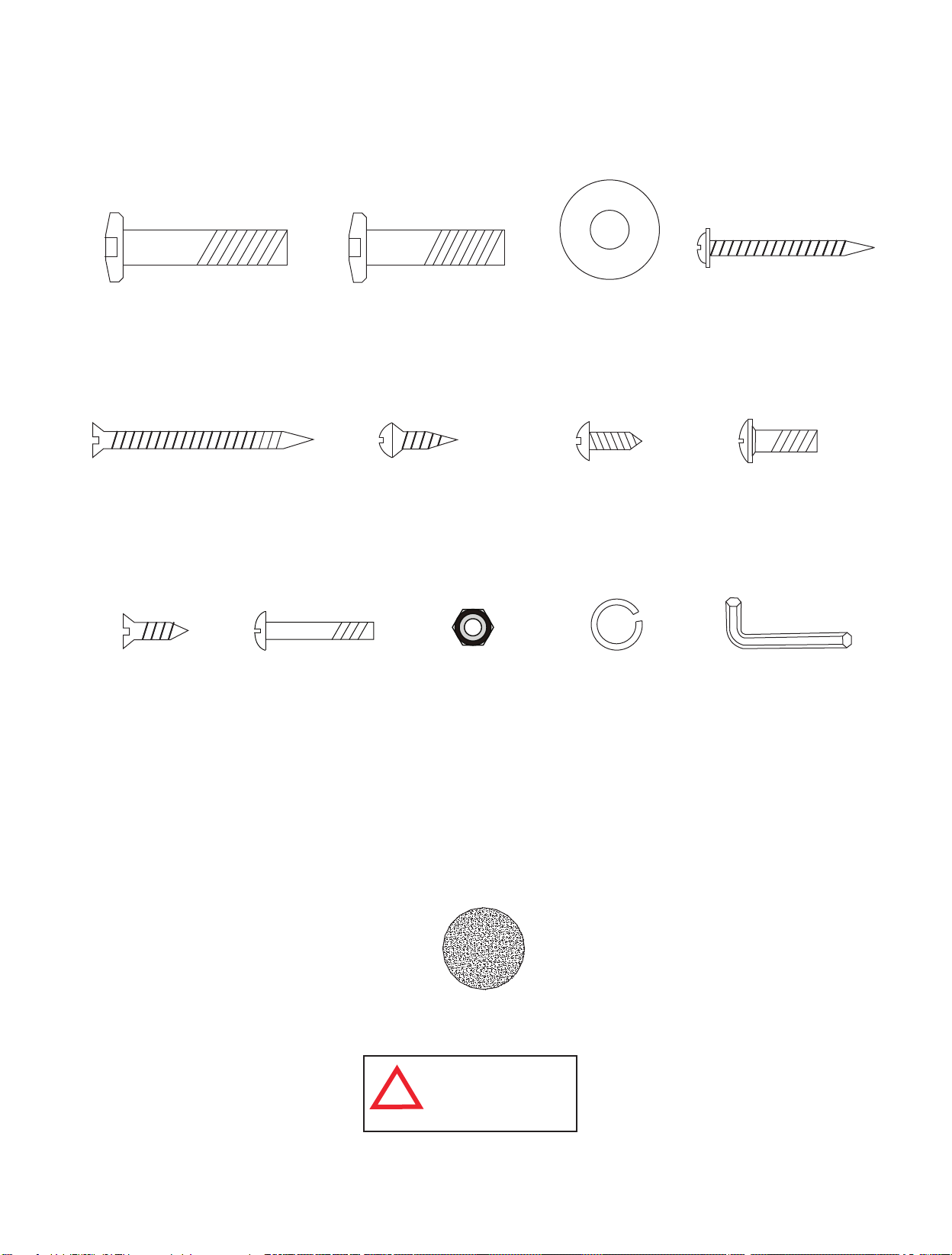
IDENTIFICADOR DE TORNILLOS
(A Escala)
H1 - 5/16” x 1-1/2”
Tornillo Allen
(8 pzas.)
H5 - #4 x 2”
Tornillo Phillips (cabeza
plana)
(6 pzas.)
H9 - #3 x 15mm
Tornillo Phillips
(cabeza plana)
(8 pzas.)
Tornillo Phillips
(Cabeza redonda)
H10 - #4 x 1”
Tornillo Phillips
(26 pzas.)
H2 - 5/16” x 1-1/4”
Tornillo Allen
(16 pzas.)
H6 - #4 x 5/8”
(6 pzas.)
H11 - #4
Tuerca de
Seguridad
(26 pzas.)
H3 - 5/16”
Rondana
(24 pzas.)
H7 - #4 x 1/2”
Tornillo Phillips
(Cabeza redonda)
(20 pzas.)
H12 - 5/16”
Arandelas de
seguridad
(24 pzas.)
H4 - #3.5 x 1-1/2”
Tornillo Phillips
(Cabeza tipo Rondana)
(12 pzas.)
H8 - 3/16” x 5/8”
Tornillo Phillips
(8 pzas.)
(No a Escala)
T1 - Llave Allen
(1 pza.)
IDENTIFICADOR DE ACCESORIOS
Todos los derechos reservados.
©
2012 Escalade Sports
(No a Escala)
A1- Pelota de Fútbol
(4 pzas.)
ADVERTENCIA:
PELIGRO DE ASFIXIA
!
Piezas pequeñas.
No adecuadas para niños
menores de 3 años.
3
Para Servicio al cliente llame 1-888-996-2729
Page 16
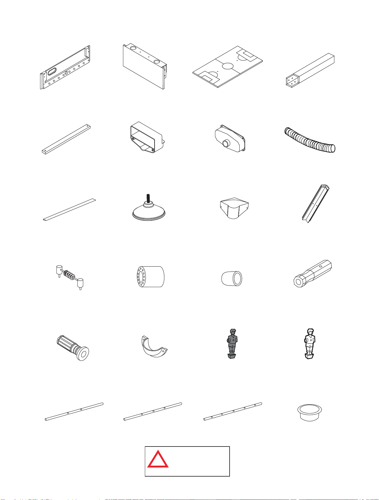
IDENTIFICADOR DE LAS PARTES
( No a Escala)
P1 - Panel Lateral
(2 pzas.)
P5 - Superficie de
Juego Support
Brace (3 pzas.)
P9 - Borde de Superficie
de Juego
(2 pzas.)
P2 - Panel del Extremo
(2 pzas.)
P6 - Portería
(2 pzas.)
P10 - Nivelador de las Patas
(4 pzas.)
P3 - Superficie de Juego (1 pza.)
P7 - Recogedor de Pelotas
(2 pzas.)
P11 - Tapa de la Esquina
(4 pzas.)
P12 - Poste de la Esquina
P4 - Pata
(4 pzas.)
P8 - Tubo de Retorno
de las Pelotas
(2 pzas.)
(4 pzas.)
P13 - Marcador (2 pzas.)
P17 - Buje de la barra
(16 pzas.)
P21 - Barra de 2 Jugadores
(2 pzas.)
Todos los derechos reservados.
©
2012 Escalade Sports
P14 - Tope de la barra
(16 pzas.)
P18 - Entrada
de Pelotas (2
pzas.)
P22 - Barra de 3 Jugadores
(4 pzas.)
ADVERTENCIA:
PELIGRO DE ASFIXIA
!
Piezas pequeñas.
No adecuadas para niños
menores de 3 años.
P15 - Tapón
para la barra
(8 pzas.)
P19 - Jugador Camisa
Roja/Shorts Negros
(13 pzas.)
P23 - Barra de 5 Jugadores
(2 pzas.)
4
Para Servicio al cliente llame 1-888-996-2729
P16 - Mango de la barra
(8 pzas.)
P20 - Jugador Camisa
Negra/Shorts Amarillos
(13 pzas.)
P24 - Portavaso
(4 pzas.)
Page 17
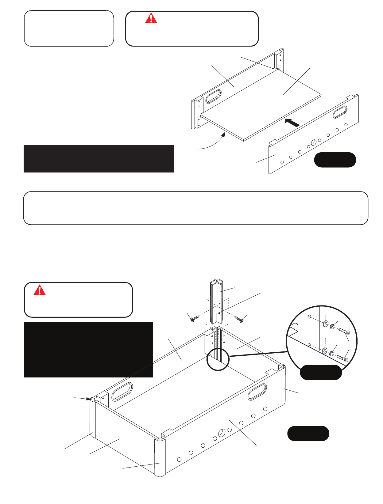
PARTES REQUERIDAS:
2 pzas. - P1 Panel Lateral
1 pza. - P3 Superficie de Juego
ADVERTENCIA
ESTE PASO REQUIERE DE DOS O MAS ADULTOS
MUY CUIDADOSAMENTE COLOQUE LA SUPERFICIE DEL
JUEGO P3 EN LAS RANURAS DEL PANEL LATERAL P1.
PASO 1:
Elija una superficie plana, nivelada y limpia para empezar
P1
Grueta
P3
a ensamblar su mesa de fútbol. Se recomienda construir
la mesa sobre la caja extendida para proteger las piezas
durante el ensamblamiento.
Es muy importante ensamblar la mesa en una
superficie plana y nivelada. Esto mantendrá que los
paneles laterales y paneles del extremo estén
"a nivel" en los bordes superiores e inferiores.
Coloque la Superficie de Juego P3 en las ranuras del
Panel Lateral P1 como se muestra en la FIGURA 1.
Nota importante: asegúrese que la superficie
de juego este centrando antes de instalar los
NOTA:
Diseño gráfico hacia
abajo.
P1
FIGURA 1
tornillos H4.
PARTES REQUERIDAS:
8 pzas. - H1 Tornillo Allen 8 pzas. - H7 Tornillo Phillips (Cabeza redonda) 2 pzas. -
8 pzas. - H3 Rondana 8 pzas. - H12 Arandelas de seguridad
4 pzas. - P12 Poste de la Esquina
1 pza. - T1 Llave Allen
P2 Panel del Extremo
PASO 2:
Coloque los Paneles del Extremo P2 en los Paneles Laterales P1 utilizando los Tornillos Allen H1 con las
Rondanas H3 ,
Deslice los Postes de la Esquina P12 en cada uno de los extremos de los Paneles Laterales P1 y de los Paneles
del Extremo P2. Utilice la Llave Allen H1. Utilice los Tornillos H7 para asegurar los
Postes de la Esquina P12 como se muestra en la FIGURA 2. Apriete los Tornillos H7, pero no los sobre apriete
ya que se dañarían.
ADVERTENCIAADVERTENCIA
ESTE PASO REQUIERE DE DOS O MAS ADULTOS.
CON MUCHO CUIDADO COLOQUE LOS POSTES DE
LAS ESQUINAS P12 EN CADA PANEL P1 Y P2
Muy importante! No apriete los tornillos H1 en este
momento. Los postes de esquina P12 deben
instalarse antes de apretar los tornillos H1.
Instalación de los postes de esquina P12 nivelara
los paneles laterales y paneles correctamente.
Apriete los tornillos de H1 sólo después de los
postes de esquina P12 están correctamente
instalados.
Arandelas de seguridad H12 como se muestra en el DETALLE A.
T1 para apretar los Tornillos
P12
H7
H7
P1
No apriete los Tornillos H1 en este momento.
NOTA: Instale los Postes de las Esquinas
P12 con la flecha apuntando hacia abajo.
H3
H12
P2
H3
H12
H1
DETALLE A
NOTA: Los Postes de
las Esquinas P12 deben
quedar nivelados as ras
con la parte inferior de
los Paneles Laterales P1
y los Paneles del Extremo
P2.
P12
Todos los derechos reservados.
©
2012 Escalade Sports
P2
P12
P12
FIGURA 2
P1
5
Para Servicio al cliente llame 1-888-996-2729
Page 18
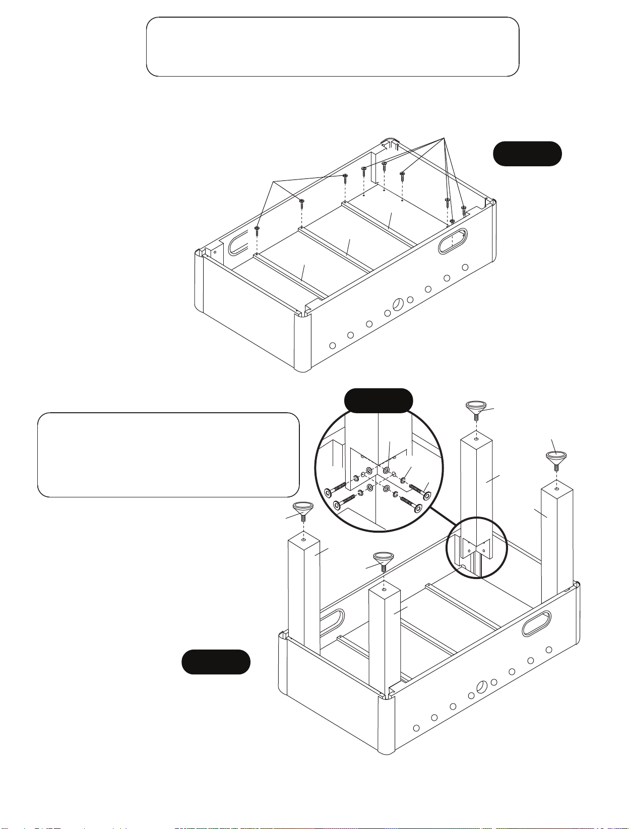
PARTES REQUERIDAS:
12 pzas. - H4 Tornillo Phillips (Cabeza tipo Rondana) 3 pzas. - P5 Soporte de
Superficie de Juego
6 pzas. - H5 Tornillo Phillips (cabeza plana)
PASO 3:
Centre y Coloque la Superficie de Juego P3 en el gabinete usando los orificios guía pre-perforados utilizando los
Tornillos H4 como se muestra en la FIGURA 3. Coloque cada uno de los Soportes de la Superficie de Juego P5 y
fíjelos con los orificios guía pre-perforados utilizando los Tornillos H5 como se muestra en la FIGURA 3.
NOTA IMPORTANTE: Asegúrese de instalar los tornillos H4 y H5
H4
exactamente como se muestra en la FIGURA 3.
Los tornillos se deben atornillar verticalmente .hacia abajo
H5
P5
P5
P5
la
FIGURA 3
PARTES REQUERIDAS:
16 pzas. - H2 Tornillo Allen 4 pzas. - P4 Pata
16 pzas. - H3 Rondana 4 pzas. - P10 Nivelador
16 pzas. - H12 Arandelas de
seguridad
PASO 4:
Colocar las Patas P4 utilizando los Tornillos
Allen
H2 con las Rondanas H3 ,
seguridad H12 como se muestra en la
FIGURA 4 y el DETALLE B.
Utilice la Llave Allen T1 para apretar los
ornillos H1.
T
Coloque/Enrosque los Niveladores P10 en
cada una de las Patas P4 como se muestra
en la FIGURA 4.
1 pza. - T1 Llave Allen
P10
Arandelas de
FIGURA 4
DETALLE B
P4
P10
H3
H12
P4
H2
P10
P10
P4
P4
Todos los derechos reservados.
©
2012 Escalade Sports
6
Para Servicio al cliente llame 1-888-996-2729
Page 19
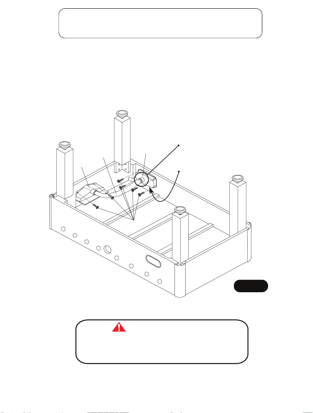
PARTES REQUERIDAS:
12 pzas. - H7 Tornillo Phillips (Cabeza redonda) 2 pzas. - P7 Recogedor de Pelotas
2 pzas. - P6 Portería 2 pzas. - P8 Tubo de Retorno de las Pelotas
PASO 5:
Centre y coloque la Portería sobre la abertura del panel del extremo usando los orificios guía pre-perforados
y utilizando los Tornillos H7 como se muestra en la FIGURA 5.
Centre y coloque el Recogedor de Pelotas P7 sobre la abertura del Panel Lateral usando los orificios guía preperforados y utilizando los Tornillos H7 como se muestra en la FIGURA 5.
Asegúrese de que la abertura circular del Tubo de Retorno de las Pelotas se encuentre hacia el suelo
(cuando la mesa esté en posición vertical).
Repita el procedimiento para ambos extremos de la mesa.
Coloque los Tubos de Retorno para el Pelota P8 entre la Portería P6 y el Recogedor de Pelotas P7 como se
muestra en la FIGURA 5.
P6
P8
P6
P8
H7
P7
NOTA:
circular del Tubo de Retorno de las
Pelotas se encuentre hacia el suelo
(cuando la mesa esté en posición
vertical)
NOTA: Asegúrese de
que la abertura este
de este lado.
Asegúrese de que la abertura
FIGURA 5
Todos los derechos reservados.
©
2012 Escalade Sports
ADVERTENCIA
ESTE PASO REQUIERE DE CUATRO O MAS ADULTOS.
CON MUCHO CUIDADO VOLTEE LA MESA HASTA QUE LAS
PATAS DE LA MESA ESTÉN SOBRE EL PISO.
TENGA CUIDADO LA MESA ESTÁ MUY PESADA.
7
Para Servicio al cliente llame 1-888-996-2729
Page 20
6 pzas. - H6 Tornillo Phillips (Cabeza redonda) 4 pzas. - P11 Tapa de la Esquina
8 pzas. - H9 Tornillo Phillips (cabeza plana) 2 pzas. - P13 Marcador
2 pzas. - P9 Borde de Superficie de juego 16 pzas. - P17 Buje de la barra
2 pzas. - P18 Entrada de Pelotas
PARTES REQUERIDAS:
4 pzas. - P24 Portavaso
PASO 6:
Despegue la capa protectora de los Bordes de la Superficie de Juego P9, después despegue la tira adhesiva
protectora de la parte inferior del Borde de la Superficie de Juego P9, Luego muy cuidadosamente póngalos a lo
largo de la Superficie de Juego P3 como se muestra en la FIGURA 6.
Coloque las Tapas de las Esquinas P11 utilizando los Tornillos H9 como se muestra en la FIGURA 6.
Apriete los Tornillos H9, pero no los sobre apriete ya que se dañarán.
Coloque los Marcadores P13 sobre la parte superior de los Paneles del Extremo P2 como se muestra en la
FIGURA 6
Inserte los Bujes de las Barras P17 dentro de ambos Paneles Laterales P1 como se muestra en la FIGURA 6.
Asegúrese que los Bujes de las Barras P17 se inserten en el Panel Lateral P1 para un ensamblamiento
NOTA IMPORTANTE: Cuando instale los bujes de la barra P17 pueden requerir el uso de un martillo de goma
para su instalación en el panel lateral. Con un martillo de goma, golpee ligeramente y firmemente el buje dentro
de su lugar. ¡NO UTILICE UN MARTILLO DE ACERO!
Si no tiene un martillo de goma desponible, entonces coloque un pedazo de madera y golpee ligeramente y
firmemente el buje dentro de su lugar.
correcto
.
Coloque Las Entradas de las Pelotas P18 utilizando los Tornillos H6 como se muestra en el DETALLE C.
Apriete los tornillos H6, pero no los sobre apriete ya que se dañarán.
Cuidadosamente introduzca - Golpeé suavemente hacia abajo los Portavasos P24 en los Paneles de los
Extremos P2, como se muestra en la FIGURA 6.
P9
P13
P24
NOTA:
Perla Roja del marcador
debe de estar en el lado
opuesto del Retorno de las
Pelotas.
NOTA:
Cuidadosamente
introduzca los Portavasos
P24 - Golpe suavemente
hacia abajo.
P17
Martillo
de goma
P13
DETALLE C
P11
H9
H9
NOTA:
Perla Roja del marcador debe
de estar en el lado opuesto
del Retorno de las Pelotas.
Todos los derechos reservados.
©
2012 Escalade Sports
FIGURA 6
8
P18
H6
Para Servicio al cliente llame 1-888-996-2729
Page 21
PARTES REQUERIDAS:
4 pzas. - H8 Tornillo Phillips 1 pza. - P21 Barra de 2 Jugadores 8 pzas. - P14 Tope de la barra
13 pzas. - H10 Tornillo Phillips 2 pzas. - P22 Barra de 3 Jugadores 4 pzas. - P15 Rod End Cup
13 pzas. - H11 Tuerca de Seguridad 1 pza. - P23 Barra de 5 Jugadores 4 pzas. - P16 Mango de la barra
13 pzas. - P19 Jugador Camisa Roja/Shorts Negros
PASO 7:
Deslice la Barra de 3 Jugadores P22, la Barra de 5
Jugadores P23 y la Barra de 2 Jugadores P21 a través
de los Bujes de la barra P17 de uno de los Paneles
Laterales P1 como se muestra en la FIGURA 7.
NOTA IMPORTANTE: Por favor, OBSERVE la
ubicación del orificio que está cerca de un extremo
de cada barra. Este es el extremo del mango de la
barra.
Coloque un Tope de la barra P14 en cada barra como se
muestra en la FIGURA 7.
Coloque los Jugadores de Camisa Roja con Shorts
Negros P19 en cada barra como se muestra en la
FIGURA 7.
NOTA IMPORTANTE: El portero debe estar a su
IZQUIERDA y su equipo (cara del jugador) viendo a la
DERECHA.
Vea la Pagina 10 en la FIGURA 10 esto le ayudará a
ensamblar correctamente los jugadores y los mangos
en las barras.
Coloque un Tope de la Barra P14 en cada barra como
se muestra en la FIGURA 7.
= P19 Jugador
Camisa Roja/Shorts
Negros
= P14 Tope de la Barra
P17
Buje de
la Barra
IZQUIERDA
P22
Barra de 3
Jugadores
VISTA DESDE ARRIBA VIENDO
HACIA ABAJO SOBRE LA MESA
P21
Barra de 2
Jugadores
P23
Barra de 5
Jugadores
P22
Barra de 3
Jugadores
Orificio/Extremo
del Mango
P14
P19
P14
P1
Panel Lateral
FIGURA 7
DERECHA
PASO 8:
Alinee el Jugador de Camisa Roja/Short Negro en
cada orificio del jugador (de la Barra) y adjúntelo utilizando
los Tornillos H10 con las Tuercas de Seguridad H11 como
se muestra en la FIGURA 8 y en el DETALLE A.
Coloque los Tapones P15 a las barras como se muestra
en la FIGURA 8.
Deslice el Mango P16 en cada extremo de la barra con el
orificio como se muestra en la FIGURA 8.
pequeño
Fije los Mangos de las barras P16 utilizado los Tornillos
H8 como se muestra en la FIGURA 8.
P19
DETALLE A
Jugador
hacia arriba
H11
H10
Barra
P19
NOTA:
Orificio
Pequeño
H8
P15
Tapón para la barra
VISTA DESDE ARRIBA VIENDO
HACIA ABAJO SOBRE LA MESA
P15
Tapón para la barra
FIGURA 8
NOTA IMPORTANTE El Jugador debe estar en
posición vertical, mientras que se fijen los Mangos de
la Barra P16 con la ranura hacia arriba.
Todos los derechos reservados.
©
2012 Escalade Sports
P16
Mango de la barra
P16
Mango de la barra
9
Para Servicio al cliente llame 1-888-996-2729
Page 22
PARTES REQUERIDAS:
4 pzas. - H8 Tornillo Phillips 1 pza. - P21 Barra de 2 Jugadores 8 pzas. - P14 Tope de la barra
13 pzas. - H10 Tornillo Phillips 2 pzas. - P22 Barra de 3 Jugadores 4 pzas. - P15 Rod End Cup
13 pzas. - H11 Tuerca de Seguridad 1 pza. - P23 Barra de 5 Jugadores 4 pzas. - P16 Mango de la barra
13 pzas. - P20 Jugador Camisa Negra/Shorts Amarillos
PASO 9:
Deslice la Barra de 3 Jugadores P22, la Barra de 5
Jugadores P23 y la Barra de 2 Jugadores P21 a través
de los Bujes de la barra P17 en el otro Panel Lateral
P1 como se muestra en la FIGURA 9.
NOTA IMPORTANTE: Por favor, OBSERVE la ubicación del orificio
que está cerca de uno de los extremos de cada
barra. Este es el extremo del mango de la barra.
Coloque un Tope de la barra P14 en cada barra como
se muestra en la FIGURA 9.
Coloque los jugadores de Camisa Negra/Shorts Amarillos
P20 en cada una de las barras como se muestra en la
FIGURA 9.
NOTA IMPORTANTE El portero debe estar a su
IZQUIERDA y su equipo (cara del jugador) viendo a
la DERECHA.
Coloque un Tope de la Barra P14 en cada barra como
se muestra en la FIGURA 9.
P20 Jugador Camisa
=
Negra/Shorts Amarillos
= P14 Tope de la barra
DERECHA
P17
Buje de
la barra
VISTA DESDE ARRIBA VIENDO
HACIA ABAJO SOBRE LA MESA
Orificio/Extremo
del Mango
P22
Barra de 3
Jugadores
P23
Barra de 5
Jugadores
P21
Barra de 2
Jugadores
IZQUIERDA
P22
Barra de 3 Jugadores
PASO 10:
Alinee el Jugador de Camisa Negra/Shorts Amarillo
P20 en cada orificio del jugador (de la Barra) y
adjúntelo utilizando los Tornillos H10 con las Tuercas
de Seguridad H11 como se muestra en la FIGURA
10 and DETALLE B.
Coloque los Tapones P15 a las barras como se
muestra en la FIGURA 10.
Deslice el Mango P16 en cada extremo de la barra
con el orificio pequeño como se muestra en la
FIGURA
10. Fije los Mangos P16 utilizado los
Tornillos H8 como se muestra en la FIGURA 10.
DETALLE B
Jugador
H10
P20
Rod
hacia arriba
H11
FIGURA 10
H8
P16
Mango de la barra
FIGURA 9
Mango de la barra
NOTA:
Orificio Pequeño
P16
NOTA IMPORTANTE: El Jugador debe estar en
posición vertical, mientras se fijan los Mangos de la
Barra P16 con la ranura hacia arriba.
Todos los derechos reservados.
©
2012 Escalade Sports
10
P15
Tapón para la barra
Para Servicio al cliente llame 1-888-996-2729
Page 23
Felicidades! Ya ha terminado de ensamblar su mesa. Por favor, Siga las Instrucciones del Uso y del
Cuidado de su mesa abajo mencionadas, para garantizar muchos años sin problemas del uso de su mesa.
CUIDADO Y USO DE SU MESA
1.
Aplique unas gotas de lubricante (no incluidas) a las barras y los cojinetes. Gire las barras
para asegurarse de que el lubricante se extienda de manera uniforme.
2.
Use spray abrillantador para limpiar todas las superficies exteriores de su mesa.de muebles
3.
Utilice un nivel de carpintero para nivelar la mesa con los niveladores de las patas.
Este producto está diseñado para su uso en INTERIORES exclusivamente.
4.
NO sentarse, subirse, apoyarse sobre la mesa.
5.
6.
NO arrastre la mesa para moverla. Si lo hace se dañarán las patas.
NO ponga bebidas sobre la mesa.
7.
LISTA DE PARTES PARA EL MODELO # G01889W
Clave N.º de Parte
H1
H2
H3
H4
H5
H6
H7
H8
H9
H10
H11
H12
T1
A1
P1
P2
P3
P4
P5
P6
P7
P8
P9
P10
P11
P12
P13
P14
P15
P16
P17
P18
P19
P20
P21
P22
P23
P24
K1
M1
01889WJH1
01889WJH2
01889WJH3
01889WJH4
01889WJH5
01889WJH6
01889WJH7
01889WJH8
01889WJH9
01889WJH10
01889WJH11
01889WJH12
01889WJT1
01889WJA1
01889WJP1
01889WJP2
01889WJP3
01889WJP4
01889WJP5
01889WJP6
01889WJP7
01889WJP8
01889WJP9
01889WJP10
01889WJP11
01889WJP12
01889WJP13
01889WJP14
01889WJP15
01889WJP16
01889WJP17
01889WJP18
01889WJP19
01889WJP20
01889WJP21
01889WJP22
01889WJP23
01889WJP24
01889WJK1
01889WJM1
Descripción
5/16” x 1-1/2” Tornillo Allen
5/16” x 1-1/4” Tornillo Allen
5/16” Rondana
#3.5 x 1-1/2” Tornillo Phillips (Cabeza tipo Rondana)
#4 x 2” Tornillo Phillips (cabeza plana)
#4 x 5/8” Tornillo Phillips (Cabeza redonda)
#4 x 1/2” Tornillo Phillips (Cabeza redonda)
3/16” x 5/8” Tornillo Phillips
#3 x 15mm Tornillo Phillips (cabeza plana)
#4 x 1” Tornillo Phillips
#4 Tuerca de Seguridad
5/16” Arandelas de seguridad
Llave Allen
Pelota de Fútbol
Panel Lateral
Panel del Extremo
Superficie de Juego
Pata
Soporte de la Superficie de Juego
Portería
Recogedor de Pelotas
Tubo de Retorno de las Pelotas
Borde de Superficie de juego
Nivelador de las patas
Tapa de la Esquina
Poste de la Esquina
Marcador
Tope de la barra
Tapón para la barra
Mango de la barra
Buje de la barra
Entrada de Pelotas
Jugador Camisa Roja/Shorts Negros
Jugador Camisa Negra/Shorts Amarillos
Barra de 2 Jugadores
Barra de 3 Jugadores
Barra de 5 Jugadores
Portavaso
Conjunto de Tornillos y Tuercas
Manual
Cant.
8
16
24
12
6
6
20
8
8
26
26
24
1
4
2
2
1
4
3
2
2
2
2
4
4
4
2
16
8
8
16
2
13
13
2
4
2
4
1
1
Todos los derechos reservados.
©
2012 Escalade Sports
11
Para Servicio al cliente llame 1-888-996-2729
Page 24

GARANTÍA LIMITADA POR 90 DÍAS
Esta garantía para consumidores de la compra original de cualquier producto ESCALADE SPORTS (en adelante
es aplicable
®
denominado el "Producto").
DURACIÓN DE LA GARANTÍA: Se garantiza este Producto al comprador original por un período de (90) días a partir de la
fecha de compra.
COBERTURA DE LA GARANTÍA: ESCALADE SPORTS le garantiza al comprador original que cualquier producto de su
fabricación está libre de defectos en los materiales y fabricación cuando se lo utiliza para el propósito establecido, bajo
condiciones normales de uso. ESTA GARANTÍA NO TIENE VALIDEZ SI EL PRODUCTO SE HA DETERIORADO POR
ACCIDENTE, USO INDEBIDO, NEGLIGENCIA, MANTENIMIENTO INCORRECTO, NO SEGUIR LAS INSTRUCCIONES QUE
VIENEN CON EL PRODUCTO U OTRAS CAUSAS NO RELACIONADAS CON DEFECTOS EN LOS MATERIALES O
FABRICACIÓN.
APLICACIÓN DE LA GARANTÍA: Durante el período de garantía de (90) días, ESCALADE SPORTS reparará o reemplazará
con otro similar, todo modelo o Producto o componente que resulte defectuoso bajo condiciones normales de uso y cuidado,
cuando nuestra inspección demuestre que a nuestra satisfacción el mismo realmente es defectuoso; sírvase contactar a nuestro
Departamento de Garantía.
1-888-996-2729 / Departamento de Garantía (Warranty Dept.)
O escríbanos a:
Escalade® Sports, Inc. - P.O. Box 889, Evansville, IN 47706 - Attn: Warranty Dept.
O por correo electrónico a:
Fuera de los gastos de envío, no se impondrá cargo alguno por la reparación o reemplazo de los productos en garantía.
ESCALADE® SPORTS recomienda asegurar los Productos por su valor antes del envío.
LIMITACIÓN DE LA GARANTÍA: TODA GARANTÍA ORIGINADA EN ESTA VENTA, INCLUYENDO EN FORMA NO
TAXATIVA, LAS GARANTÍAS IMPLÍCITAS DE COMERCIALIZACIÓN Y APTITUD PARA UN FIN ESPECÍFICO, TENDRÁ VIGENCIA
POR UN PLAZO DE (90) DÍAS. ESCALADE® SPORTS NO SERÁ RESPONSABLE POR LA PÉRDIDA DE USO DEL PRODUCTO U
OTROS COSTOS INCIDENTALES O RELACIONADOS, PERJUICIOS O PERDIDAS GENERADAS POR EL CONSUMIDOR
ANTE CUALQUIER OTRO USO.
Algunos estados no permiten la exclusión o limitación de las garantías implícitas o daños incidentales o conexos, de modo que
las limitaciones que anteceden pueden no ser aplicabes en su caso.
RECURSOS LEGALES: Esta garantía le otorga algunos derechos específicos además de otros derechos que varían según el
estado.
Todos los derechos reservados.
©
2012 Escalade Sports
12
Para Servicio al cliente llame 1-888-996-2729
 Loading...