

Page 1

W e striv e t o ensur e tha t ou r product s ar e o f th e highes t quality
an d fre e o f manufacturin g defect s o r missin g parts . Howev e r , if
yo u hav e an y problem s wit h you r ne w product,
D O NO T RETUR N I T T O TH E S T ORE ,
pleas e contac t u s tol l fre e @:
1-88 8 -996-2729
F AX : 1-866-873-3531
O r writ e to:
Escal a d e Spor t s
Cust o me r Servi c e Depa r tme n t
P .O . Bo x 8 8 9
Evansvill e I N 47706
Please
Whe n contactin g Escalad e Sport s pleas e provid e you r mode l numbe r , d at e
cod e (i f a pplicable ) an d par t n umbe r i f requestin g a replacemen t part . T hes e
number s ar e locate d o n th e product , packaging , an d t hi s owner s m anual .
Y ou r Mode l Numbe r
Dat e Cod e
hav e you r mode l numbe r whe n inquirin g abou t parts.
G04864W New Version
2 - G04864W - - WJ
Purchase Dat e
PLEASE RETAIN THIS INSTRUCTION MANUAL FOR FUTURE REFERENCE
All Rights Reserved.
©
2012 Escalad e Sports
1
Fo r Custome r Servic e Cal l 1-888-996-2729
Page 2
IMPORTANT! READ EACH STEP
IN THIS MANUAL BEFORE YOU
BEGIN THE ASSEMBLY.
TWO
ADULTS ARE REQUIRED TO ASSEMBLE
THIS ATOMIC AVENGER 8FT HOCKEY TABLE
Tools Required:
T1 - Wrench (Included)
Phillips Screwdriver
Furniture Polish and Cloth
Assembly Tips
Make sure you understand the following tips before you begin to assemble your hockey table.
1. Start all bolts by hand before tightening.
2. Some drawings or images in this manual may not look exactly like your product. Please
read and understand the text before starting each assembly step.
READ AND FOLLOW ALL ASSEMBLY, OPERATION, AND
SAFETY INSTRUCTIONS CAREFULLY. AT LEAST TWO
ADULTS ARE NEEDED TO PUT THIS HOCKEY TABLE
TOGETHER.
All Rights Reserved.
©
2012 Escalade Sports
2
For Customer Service Call 1-888-996-2729
Page 3
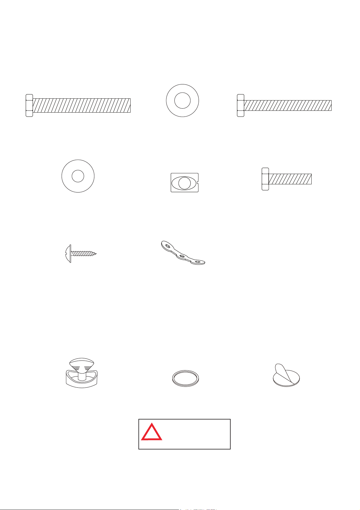
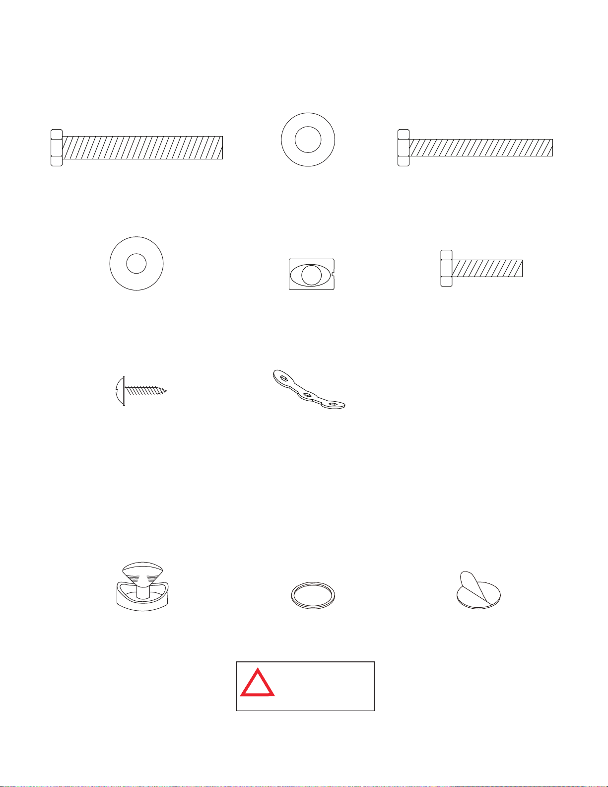
HARDWARE IDENTIFIER
( To Scale)
H1 - 8mm x 57mm
Hex Bolt (12 pcs)
H4 - 6mm x 19mm
Flat Washer (16 pcs)
H7 - 3mm x 15mm
Phillips Washer Head
Screw (4 pcs)
H2 - 8mm x 19mm
Flat Washer (12 pcs)
H5 - Barrel Nut (8 pcs)
(Not to Scale)
T1 - Wrench (1 pc)
H3 - 6mm x 50mm
Hex Bolt (8 pcs)
H6 - 6mm x 25mm
Hex Bolt (8 pcs)
A1 - Striker (2 pcs) A2 - Puck (2 pcs)
All Rights Reserved.
©
2012 Escalade Sports
ACCESSORY IDENTIFIER
(Not to Scale)
A
WARNING:
CHOKING HAZARD
!
Small parts.
Not for children under 3 yrs.
3
For Customer Service Call 1-888-996-2729
A3 - Felt Pad (2 pcs)
NOTE: A3 Felt Pads may
already be attached to
A1 Strikers.
Page 4
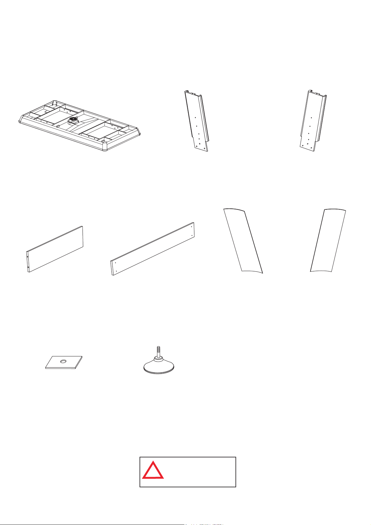
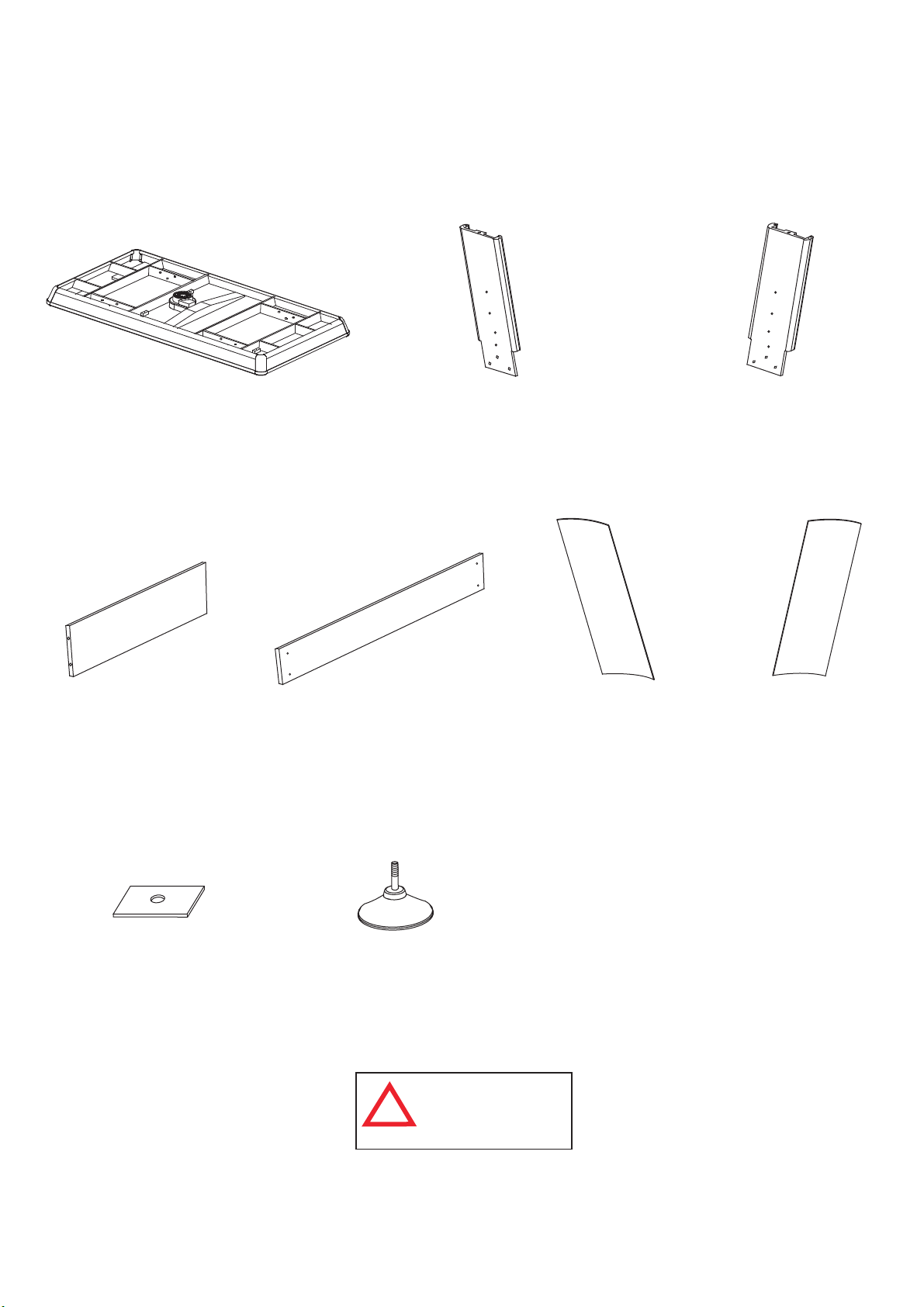
PARTS IDENTIFIER
( Not to Scale)
P1 - Hockey Table Cabinet (1 pc) P2 - Right Leg (2 pcs) P3 - Left Leg (2 pcs)
P4 - End Leg
Panel (2 pcs)
P8 - Leg Panel
Support Block
(4 pcs)
NOTE: Packed
with Hardware Kit
P5 - Side Leg
Panel (2 pcs)
P9 - Leg Leveler (4 pcs)
WARNING:
CHOCKING HAZARD
!
Small parts.
Not for children under 3 yrs.
P6 - Right Cover
Leg Panel (2 pcs)
P7 - Left Cover
Leg Panel (2 pcs)
All Rights Reserved.
©
2012 Escalade Sports
4
For Customer Service Call 1-888-996-2729
Page 5
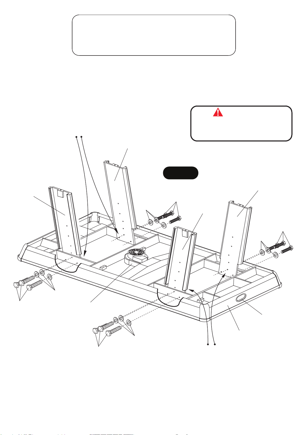
PARTS REQUIRED:
12 pcs - H1 Hex Bolt 2 pcs - P2 Right Leg
12 pcs - H2 Flat Washer 2 pcs - P3 Left Leg
1 pc - P1 Hockey Table Cabinet 1 pc - T1 Wrench
STEP 1:
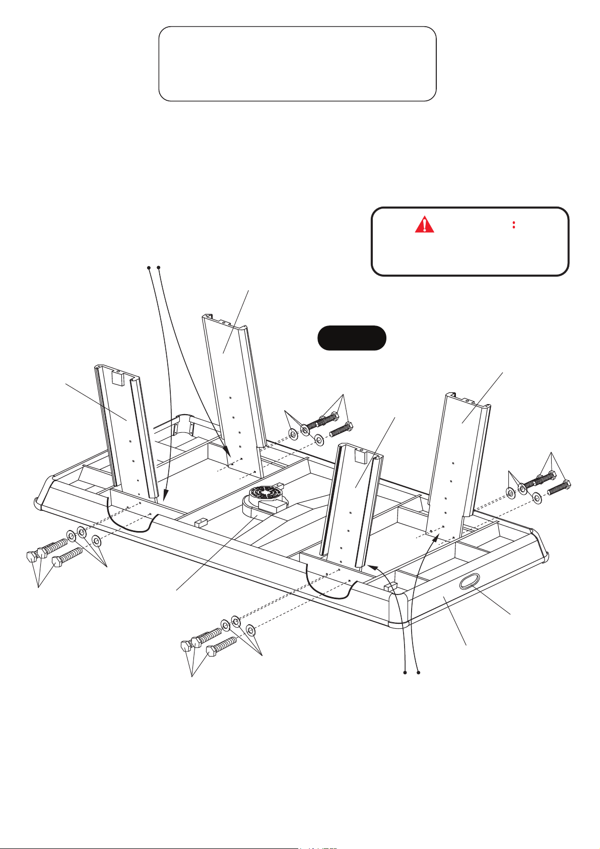
To assemble this table, leave P1 Hockey Table Cabinet face down in the carton lid.
Attach P2 Right Legs and P3 Left Legs using H1 Hex Bolts with H2 Flat Washers as shown in FIGURE 1.
Do not tighten H1 Bolts until completion of STEP 4.
IMPORTANT NOTE:
BE SURE P2-RIGHT LEGS AND
P3-LEFT LEGS ARE INSTALLED
INSIDE OF SUPPORT BEAMS AS
PER DIAGRAM.
P3
P2
H2
CAUTION
PLEASE BE SURE TO ASSEMBLE P2-RIGHT
LEGS AND P3-LEFT LEGS EXACTLY AS PER
DIAGRAM.
FIGURE 1
P3
H1
P2
H1
H2
H1
All Rights Reserved.
©
2012 Escalade Sports
H2
C7
H1
H2
C8
P1
IMPORTANT NOTE:
BE SURE P2-RIGHT LEGS AND
P3-LEFT LEGS ARE INSTALLED
INSIDE OF SUPPORT BEAMS AS
PER DIAGRAM.
5
For Customer Service Call 1-888-996-2729
Page 6
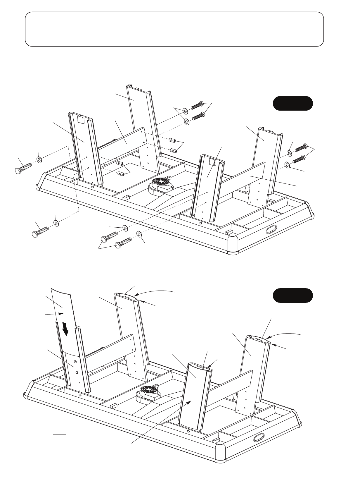
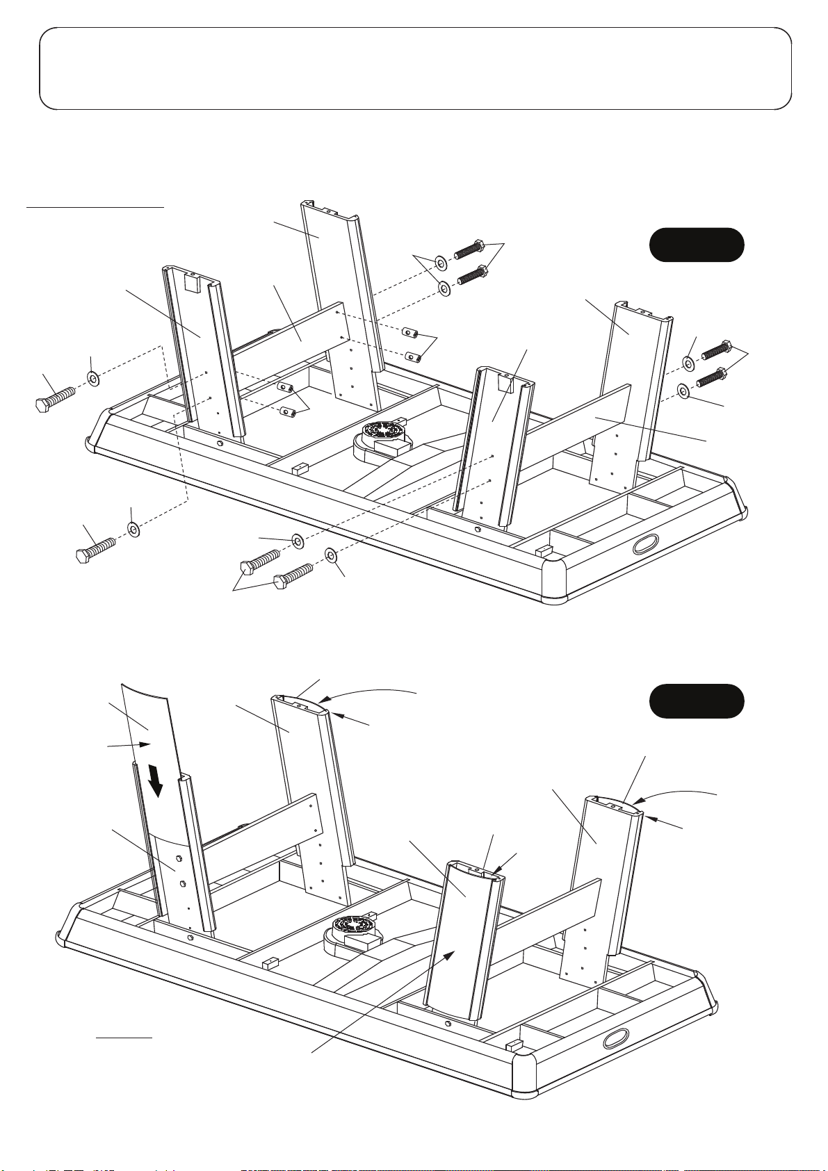
PARTS REQUIRED:
8 pcs - H3 Hex Bolt 8 pcs - H5 Barrel Nut 2 pcs - P6 Right Cover Leg Panel 1 pc - T1 Wrench
8 pcs - H4 Flat Washer 2 pcs - P4 End Leg Panel 2 pcs - P7 Left Cover Leg Panel
STEP 2:
Attach P4 End Leg Panels between two legs of P2 Right Legs and P3 Left Legs using H3 Hex Bolts with H4 Flat
Washers and H5 Barrel Nuts as shown in FIGURE 2. Use T1 Wrench to tighten all bolts.
Important Note: Tighten, but do not over tighten H3 Bolts.
P2
H4
H3
FIGURE 2
P4
H4
P3
H5
P2
P3
H4
H3
H3
H5
H4
P4
H4
H3
H4
H4
H3
STEP 3:
Carefully bow and slide P6 Right Leg Panel and P7 Left Leg Panel into the grooves of each leg assembly as
shown in FIGURE 3.
P7
White Laminate
on this side
P2
P6
Flush
White Laminate
on this side
FIGURE 3
P7
P3
NOTE: P6 and P7 Leg
Panel must be flush
with bottom of Legs.
All Rights Reserved.
©
2012 Escalade Sports
White Laminate
on this side
P6
P3
White Laminate
on this side
P2
Flush
6
For Customer Service Call 1-888-996-2729
Flush
Page 7
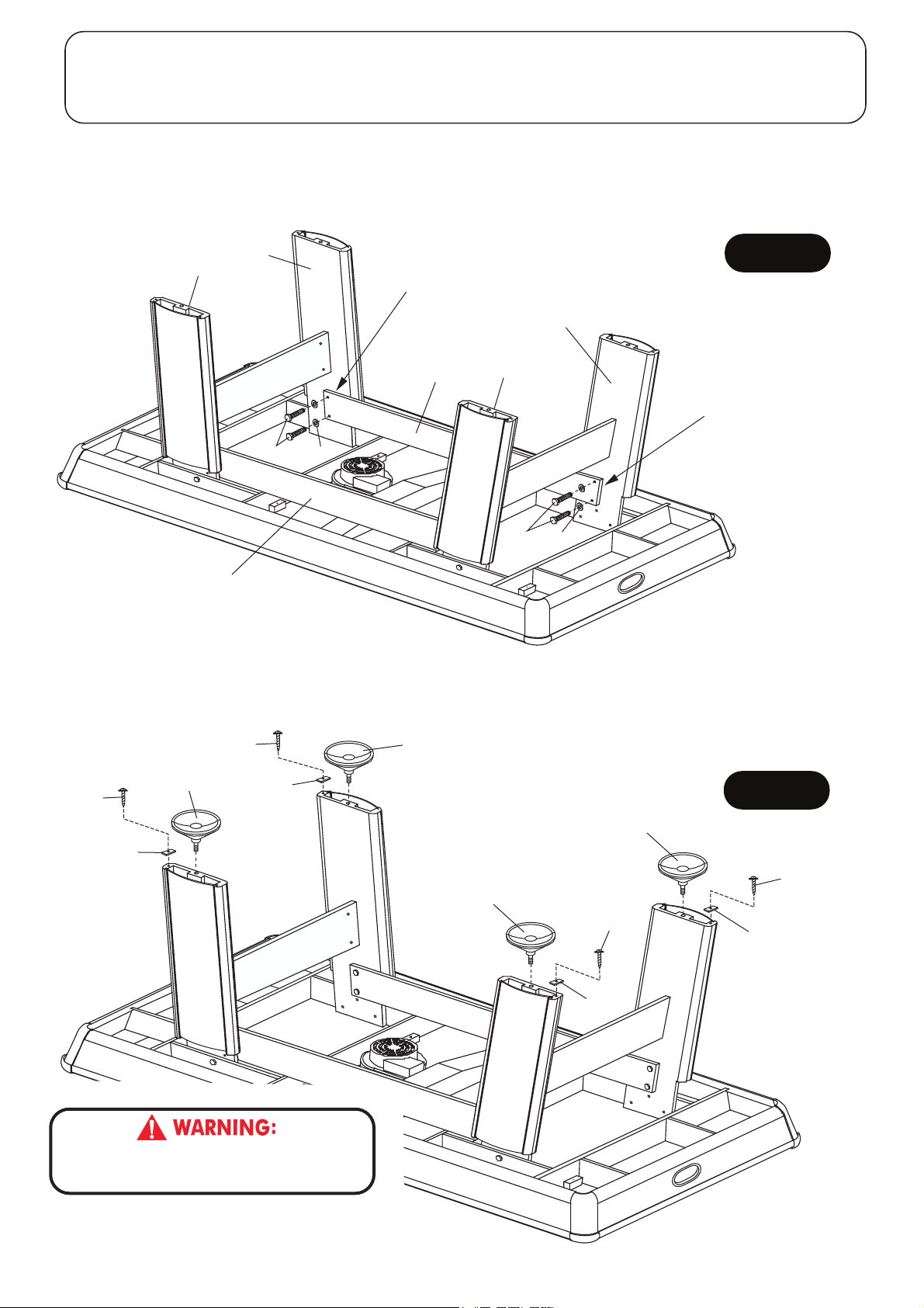
PARTS REQUIRED:
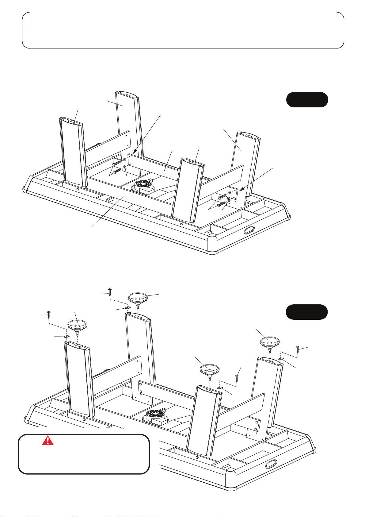
8 pcs - H6 Hex Bolt 4 pcs - H7 Screw 4 pcs - P8 Leg Panel Support Block 1 pc - T1 Wrench
8 pcs - H4 Flat Washer 2 pcs - P5 Side Leg Panel 4 pcs - P9 Leg Leveler
STEP 4:
Attach P5 Side Leg Panels between P2 Right Legs and P3 Left Legs using H6 Hex Bolts with H4 Flat Washers as
shown in FIGURE 4. Use T1 Wrench to tighten all bolts. Remember to tighten all H1 Leg Bolts from STEP 1.
FIGURE 4
P3
P2
NOTE: Small wooden tab on end of
P5 Side Panel must face the leg.
P3
P2
H6
NOTE: Small wooden tab
on end of P5 Side Panel
must face the leg.
H4
H6
P5
H4
P5
STEP 5:
Attach P8 Leg Panel Support Blocks to bottom of Leg assembly using pre-drilled pilot hole with H7 Screws as
shown in FIGURE 5. Tighten, but do not strip out H7 screws.
Thread P9 Leg Levelers into the Leg assembly as shown in FIGURE 5.
H7
H7
P9
P8
P8
THIS STEP REQUIRES FOUR OR MORE ADULTS.
VERY CAREFULLY TURN THE TABLE OVER AND SET IT ON
ITS LEGS. BE CAREFUL. THE TABLE IS VERY HEAVY.
P9
P9
P8
H7
FIGURE 5
P9
H7
P8
All Rights Reserved.
©
2012 Escalade Sports
7
For Customer Service Call 1-888-996-2729
Page 8
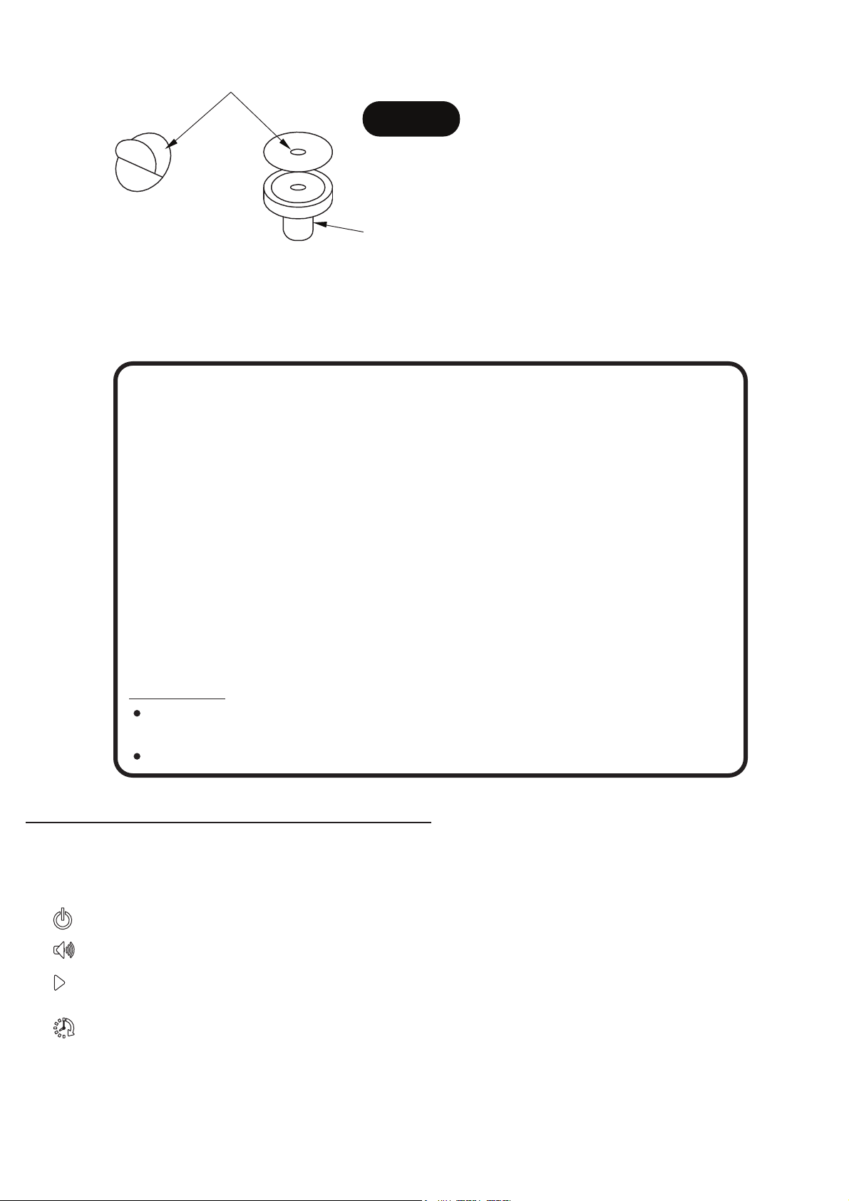
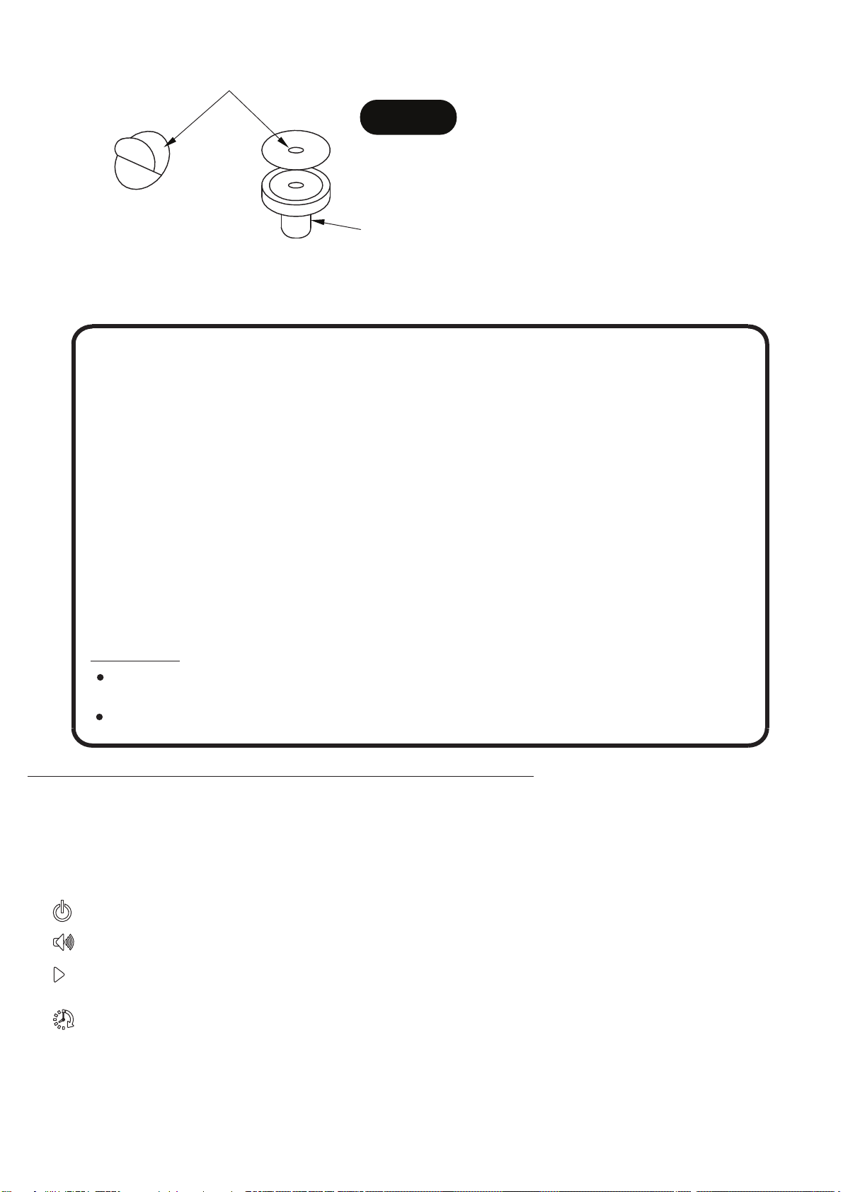
STEP 6:
Peel the backing off A3 Felt Pad and attach to A1 Striker as shown in FIGURE 6.
A3
FIGURE 6
NOTE: A3 Felt Pads
may already be attached
to A1 Strikers.
A1
Congratulations! You have now assembled your Atomic Hockey Table. Please note the
instructions below to ensure many years of trouble free use of your Atomic Hockey Table.
CARE AND USE OF YOUR ATOMIC HOCKEY TABLE
1. Use only a suitable 120v AC household outlet, and insure the cord is not a
trip hazard.
2. Spray furniture polish is recommended to both protect the play field and
increase the puck speed. Apply and wipe off with the air motor on.
3. Use a carpenters level to properly level table using the leg levelers.
4. This product is intended for INDOOR use only.
5. DO NOT operate the motor if the cord is damaged in any way.
6. DO NOT sit, climb or lean on the table.
7. DO NOT drag the table when moving it. This will damage the legs.
8. DO NOT set drinks on the table.
9. It is suggested that this table be placed close to a wall thus allowing the air
motor cord to NOT be a trip hazard. Always turn air motor off when table is
NOT in use.
Suggestion:
The purchase of a 8 ft Pool Table cover will both protect and help keep
table clean while table is not in use.
See Page 10 about ordering information of additional strikers and pucks.
ELECTRONIC SCORER OPERATION:
1. Plug the power cord from the ON/OFF switch into a wall outlet.
2. Press the red ON/OFF switch on end apron to turn the air motor on.
3. This game includes a new touch panel control box with familiar icons to control the electronic scorer.
Each icon is discribed below.
= Power ON/OFF – Press this button to turn the electronic scorer ON or OFF.
= Sound ON/OFF – Press this button while the game is on to turn the sound ON or OFF.
= Start / Reset – Press this button to begin the game. Press this button at end of game to reset back to the same
game option.
= Time – Press this button to select time options 15 minutes, 10 minutes, 5 minutes or “No Time Limit”.
NOTE: If no score has been made or the button is not pressed for 15 minutes, the scoreboard will automatically
turn off. However we suggest turning the power off when the game will not be used for an extended period of time.
All Rights Reserved.
©
2012 Escalade Sports
8
For Customer Service Call 1-888-996-2729
Page 9
HOCKEY GAME RULES:
1. This game is designed to be played with two (2) players, one at each end, or with four (4) players, two at each
end of the game table. See Page 10 about ordering information of additional strikers and pucks.
2. Flip a coin to determine who will begin play, or a face-off can be held at the center of the table.
3. Play begins when the puck is placed on the playing surface. Players must hit the puck with the strikers and
attempt to shoot into the opponent’s goal.
4. One point is awarded when a puck is shot into the opponent’s goal.
5. Winning the game: the winning score is accomplished by being the first player to reach a predetermined score
or by being the player to score the most points within a given period of time.
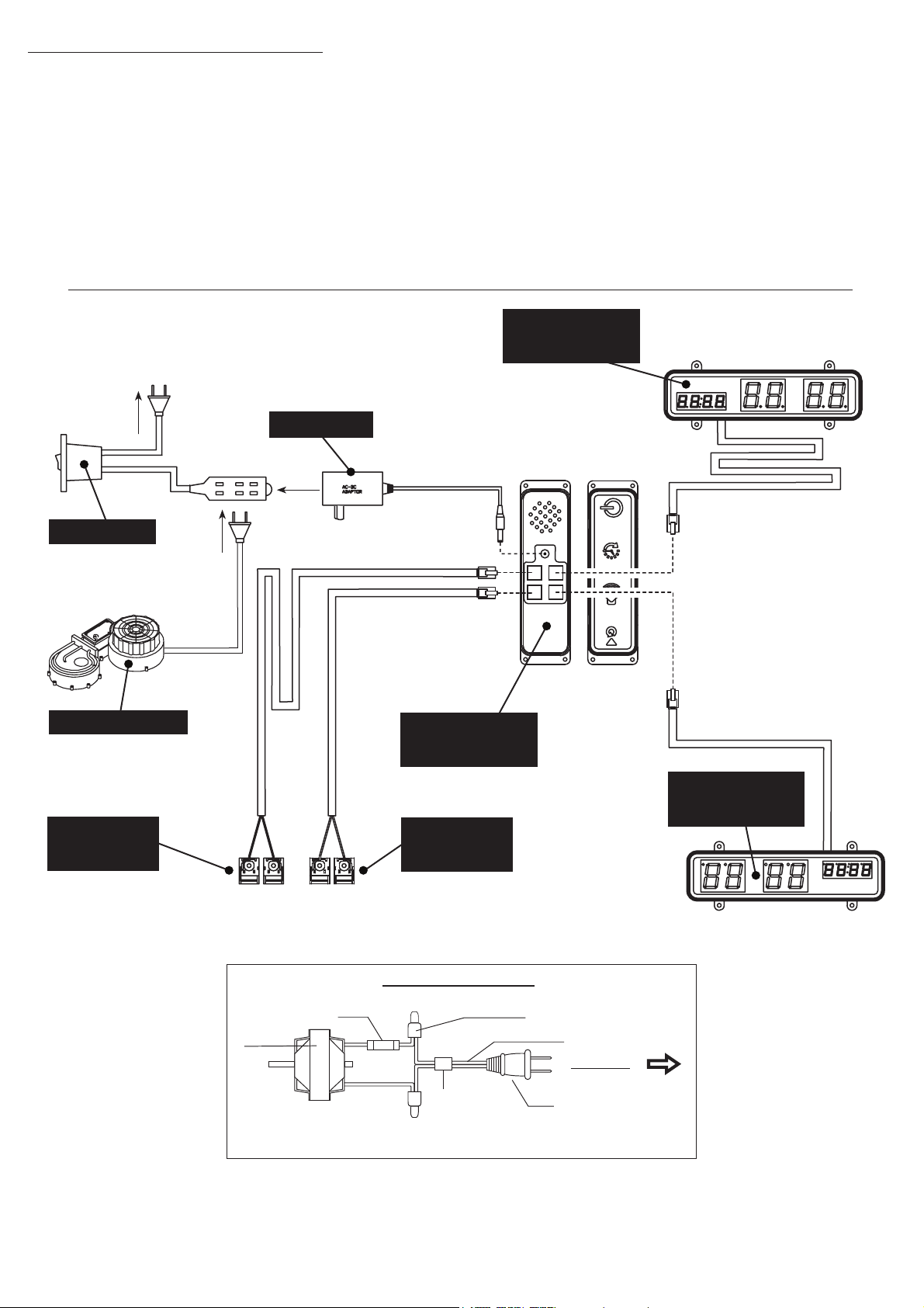
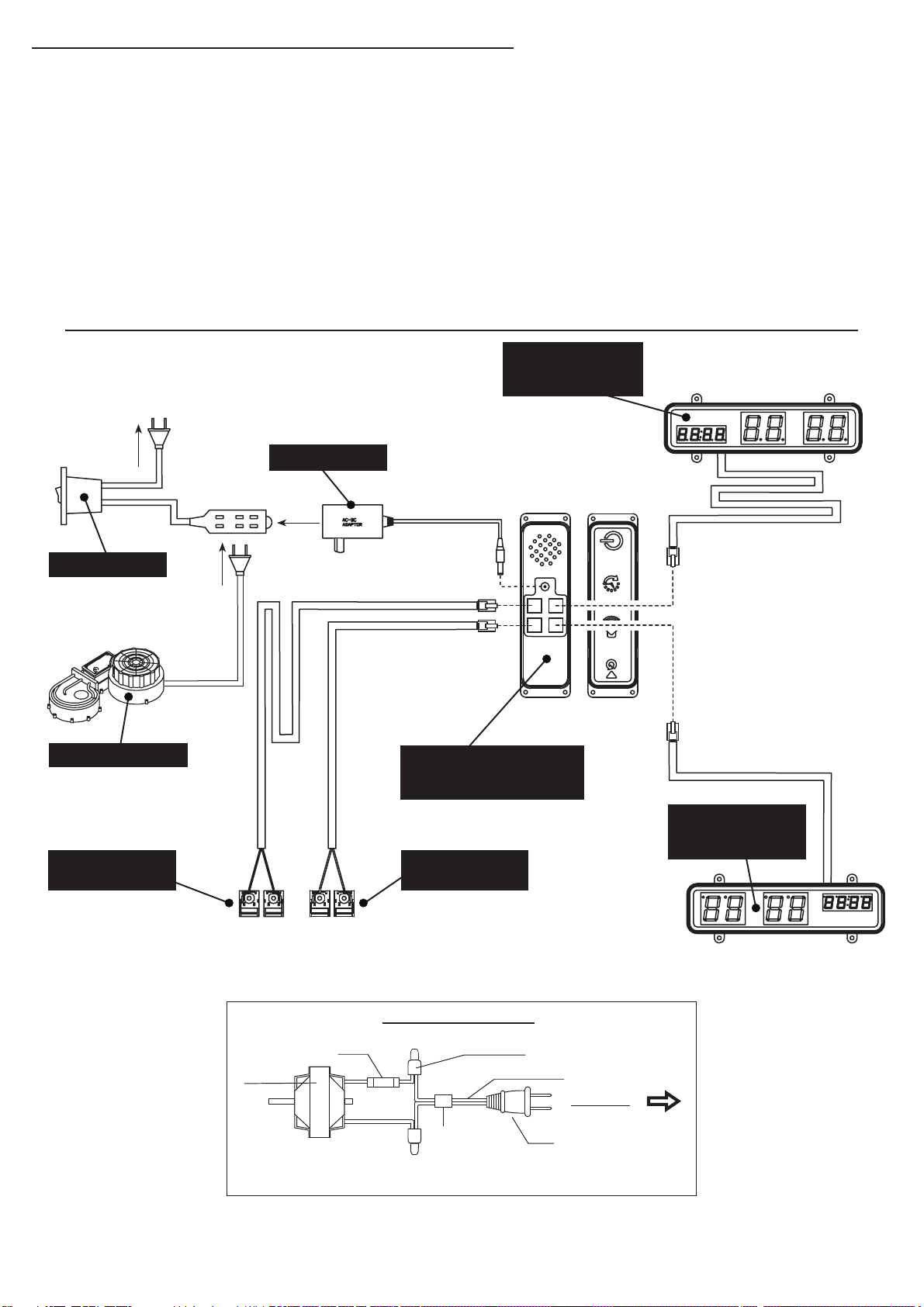
ELECTRICAL CONNECTIONS & SPARE PARTS DRAWINGS
4
C3L - LED Scorer
Display with Long
Wire
To Wall Outlet
C5 - Adapter
C6 - ON/OFF
C7 - Blower Motor
C1R - Main
BACK
VIEW
FRONT
VIEW
Electronic Unit
with Control Panel
C4L - Scoring
Sensors with
Long Wire
MOTOR
C4S - Scoring
Sensors with
Short Wire
SCHEMATIC DIAGRAM
THERMAL
PROTECTOR
ELECTRIC RATING : AC 100-125 V, 60 HZ, 129 W, 2800 RPM
CONNECTOR
ON/OFF SWITCH
C3S - LED Scorer
Display with Short
Wire
SPT-2 POWER CORD
AC 100-125V
POLARIZED PLUG
All Rights Reserved.
©
2012 Escalade Sports
9
For Customer Service Call 1-888-996-2729
Page 10
PRODUCT PARTS LIST FOR MODEL # G04864W New Version
Key # Part #
H1
H2
H3
H4
H5
H6
H7
T1
A1
A2
A3
P1
P2
P3
P4
P5
P6
P7
P8
P9
C1R
C3S
C3L
C4S
C4L
C5
C6
C7
C8
K1
M1
04864WJH1
04864WJH2
04864WJH3
04864WJH4
04864WJH5
04864WJH6
04864WJH7
04864WJT1
04864WJA1
04864WJA2
04864WJA3
04864WJP1
04864WJP2
04864WJP3
04864WJP4
04864WJP5
04864WJP6
04864WJP7
04864WJP8
04864WJP9
04864WJC1R
04864WJC3S
04864WJC3L
04864WJC4S
04864WJC4L
04864WJC5
04864WJC6
04864WJC7
04864WJC8
04864WJK1
04864WJM1
Description
8mm x 57mm Hex Bolt
8mm x 19mm Flat Washer
6mm x 50mm Hex Bolt
6mm x 19mm Flat Washer
Barrel Nut
6mm x 25mm Hex Bolt
3mm x 15mm Phillips Washer Head Screw
Wrench
Striker
Puck
Felt Pad
Hockey Table Cabinet ( no blower motor )
Right Leg
Left Leg
End Leg Panel
Side Leg Panel
Right Cover Leg Panel
Left Cover Leg Panel
Leg Panel Support Block
Leg Leveler
Main Electronic Unit with Control Panel
LED Scorer with Short Wire
LED Scorer with Long Wire
Scoring Sensors with Short Wire
Scoring Sensors with Long Wire
Adapter
ON/OFF Switch
Blower Motor
Puck Return Tray
Hardware Kit
Owner’s Manual (New Version)
Qty.
12
12
8
16
8
8
4
1
2
2
2
1
2
2
2
2
2
2
4
4
1
1
1
1
1
1
1
1
2
1
1
** Additional A1 Strikers and A2 Pucks are available for purchase by calling or e-mailing
Escalade Sports.
All Rights Reserved.
©
2012 Escalade Sports
10
For Customer Service Call 1-888-996-2729
Page 11

90 DAY LIMITED WARRANTY
This consumer warranty extends to the original consumer purchase of any ESCALADESPORTS
Product (hereinafter referred as the "Product").
WARRANTY DURATION: This Product is warranted to the original consumer purchase of a period of 90 days from the original purchase.
WARRANTY COVERAGE: ESCALADE SPORTS warrants to the original Consumer Purchaser
that any Product of its manufacture is free from defects in material and workmanship when used
for the intended purpose under normal use and conditions. THIS WARRANTY IS VOID IF THE
PRODUCT HAS BEEN DAMAGED BY ACCIDENT, UNREASONABLE USE, NEGLIGENCE,
IMPROPER SERVICE, FAILURE TO FOLLOW INSTRUCTIONS PROVIDED WITH THE PRODUCT OR OTHER CAUSES NOT ARISING OUT OF DEFECTS IN MATERIAL AND WORKMANSHIP.
WARRANTY PERFORMANCE: During the above 90 day warranty period, ESCALADESPORTS
shall repair or replace with a comparable model, and Product, or component thereof, which may
prove defective under normal use and proper care, and which our examination shall disclose to
our satisfaction to be thus defective, please contact our Warranty Dept.
1-888-996-2729 / Warranty Dept.
Or Write us at:
Escalade® Sports, Inc. - P.O. Box 889, Evansville, IN 47706
Attn: Warranty Dept.
Or E-mail us at:
Other than shipping requirements no charge will be made for such repair or replacement of inwarranty Products. ESCALADE SPORTS strongly recommends that the Product is insured for
value prior to mailing.
WARRANTY DISCLAIMERS: ANY IMPLIED WARRANTIES ARISING OUT OF
THIS SALE, INCLUDING BUT NOT LIMITED TO THE IMPLIED WARRANTIES OF
MERCHANTABILITY AND FITNESS FOR A PARTICULAR PURPOSE, ARE LIMITED IN DURATION TO THE ABOVE 90 DAY PERIOD. ESCALADE SPORTS
SHALL NOT BE LIABLE FOR LOSS OF USE OF THE PRODUCT OR OTHER
CONSEQUENTIAL OR INCIDENTAL COSTS, EXPENSES OR DAMAGES INCURRED BY THE CONSUMER OF ANY OTHER USE.
Some states do not allow the exclusion or limitation of implied warranties or consequential or
incidental damages, so the above limitations or exclusions may not apply to you.
LEGAL REMEDIES: This warranty gives you specific legal rights and you may also have other
rights which may vary from state to state.
All Rights Reserved.
©
2012 Escalade Sports
11
For Customer Service Call 1-888-996-2729
Page 12

Nosotros tratamos de asegurarnos que nuestros productos sean
de la más alta calidad y libre de problemas, como defectos de
fabricación ó partes incompletas. Sin embargo, Si usted tiene
algún problema con su producto, por favor
NO LO REGRESE A LA TIENDA
pongase en contacto con nosotros llamando gratis al:
1-888 -996-2729
FAX : 1-866-873-3531
O escriba a:
Escalade Sports
Departamento de Atención al
Cliente
P.O.Bo x 889
Evansville IN 47706
Visite nuestro sitioWeb en:
Por favor tenga el n
Al contactar a Escalade Sports, por favor incluya su número de modelo, código
de fecha (si lo hubiera) y el número de parte en caso de solicitar una parte. Estos
números se ubican en el producto, en el empaque y en el manual del usuario.
Número de modelo:
Código de fecha:
Fecha de Compra:
G04864W Nueva Versión
2 - G04864W - - WJ
úmero de modelo cuando solicite partes.
CONSERVE ESTE MANUAL DE INSTRUCCIONES PARA REFERENCIA.
Todos los derechos reservados.
stropSedalacsE1202©
12
Para Servicio al cliente llame 1-888-996-2729
Page 13
IMPORTANTE! LEA TODOS LOS
PASOS DE ESTE MANUAL ANTES
DE COMENZAR A ARMAR.
SE REQUIEREN DOS ADULTOS PARA
ENSAMBLAR ESTA MESA “ATOMIC AVENGER”.
Herramientas Necesarias:
T1 - Llave Allen (Incluida)
Desarmador Phillips
Abrillantador para muebles y un paño
IMPOR
LOS DIBUJOS DE ESTE MANUAL
PUEDEN HABERSE EXAGE
O MODIFICADO PARA
MOSTRAR LOS DE
TANTE!
RADO
TALLES.
Consejos de ensamblamiento
úrese de que comprende los siguientes consejos antes de comenzar a armar la mesa.
Aseg
1. Coloque todos los tornillos manualmente antes de apretarlos.
2. Algunos dibujos o im
a su producto. Asegúrese de leer y comprender el texto antes de comenzar
cada paso.
LEA Y SIGA LAS INSTRUCCIONES DE ENSAMBLAR,
EL FUNCIONAMIENTO Y SEGURIDAD ATENTAMENTE.
SE REQUIEREN POR LO MENOS DOS ADULTOS
ágenes de este manual puede que no se vean exactamente igual
PRECAUCIÓN:
PARA ARMAR ESTA MESA
Todos los derechos reservados.
©
2012 Escalade Sports
13
Para Servicio al cliente llame1-888-996-2729
Page 14
IDENTIFICADOR DE TORNILLOS
(A Escala)
H1 - 8mm x 57mm
Tornillo (12 pzas.)
H4 - 6mm x 19mm
Rondana (16 pzas.)
H7 - 3mm x 15mm
Tornillo Phillips (cabeza tipo arandela)
(4 pzas.)
H2 - 8mm x 19mm
Rondana (12 pzas.)
H5 - Tuerca del Barril (8 pzas.)
(No a Escala)
T1 - Llave (1 pza.)
H3 - 6mm x 50mm
Tornillo (8 pzas.)
H6 - 6mm x 25mm
Tornillo (8 pzas.)
IDENTIFICADOR DE ACCESORIOS
A
A1 - Mazo (2 pzas.) A2 - Disco (2 pzas.)
Todos los derechos reservados.
©
2012 Escalade Sports
(No a Escala)
ADVERTENCIA:
PELIGRO DE ASFIXIA
!
Piezas pequeñas.
No adecuadas para niños
menores de 3 años.
14
A3 - Fieltro para el Mazo (2 pzas.)
NOTA: Fieltro puede
estar ya en los mazos A1.
Para Servicio al cliente llame 1-888-996-2729
A3
Page 15
IDENTIFICADOR DE LAS PARTES
(No a Escala)
P1 - Mesa de hockey de aire (1 pza.) P2 - Pata (Derecha) (2 pzas.) P3 - Pata (Izquierda) (2 pzas.)
P4 - Tabla del
extremo para las
patas (2 pzas.)
P8 - Soporte para la Cubierta
de la Pata (4 pzas.)
NOTA: Empacado con el Conjunto
de Tornillos y Tuercas
P5 - Tabla lateral para
las patas (2 pzas.)
P9 - Nivelador de las patas (4 pzas.)
P6 - Cubierta de
la Pata (Derecha)
ADVERTENCIA:
PELIGRO DE ASFIXIA
!
Piezas pequeñas.
No adecuadas para niños
menores de 3 años.
(2 pzas.)
P7 - Cubierta de la
Pata (Izquierda)
(2 pzas.)
Todos los derechos reservados.
©
2012 Escalade Sports
15
Para Servicio al cliente llame 1-888-996-2729
Page 16
PARTES REQUERIDAS:
12 pzas. - H1 Tornillo 2 pzas. - P2 Pata (Derecha)
12 pzas. - H2 Rondana 2 pzas. - P3 Pata (Izquierda)
1 pza. - P1 Mesa de hockey de aire 1 pza. - T1 Llave
PASO 1:
Para ensamblar esta mesa, coloque la Mesa de Hockey de aire P1 boca abajo sobre el cartón.
Coloque las Patas derechas P2 y las patas izquierdas P3 utilizando los Tornillos H1 con las
Rondanas H2 como se muestra en la FIGURA 1.
No apriete los tornillos H1 hasta completar el PASO 4.
NOTA IMPORTANTE: ASEGURESE
QUE LAS PATAS DERECHAS P2 Y
LAS PATAS IZQUIERDAS P3 ESTÉN
INSTALADAS DENTRO DE LA
BARRA DE SOPORTE COMO SE
MUESTRA EN EL DIAGRAMA.
P3
P2
H2
AVISO:
ASEGURESE QUE LAS PATAS DERECHAS P2
Y LAS PATAS IZQUIERDAS P3 ESTÉN
ENSAMBLANDAS EXACTAMENTE COMO SE
MUESTRA EN EL DIAGRAMA.
FIGURA 1
P3
H1
P2
H1
H2
H2
H1
Todos los derechos reservados.
©
2012 Escalade Sports
C7
H1
H2
16
C8
P1
NOTA IMPORTANTE: ASEGURESE
QUE LAS PATAS DERECHAS P2 Y
LAS PATAS IZQUIERDAS P3 ESTÉN
INSTALADAS DENTRO DE LA
BARRA DE SOPORTE COMO SE
MUESTRA EN EL DIAGRAMA.
Para Servicio al cliente llame 1-888-996-2729
Page 17
PARTES REQUERIDAS:
8 pzas. - H3 Tornillo 8 pzas. - H5 Tuerca del Barril 2 pzas. - P6 Cubierta de la Pata (Derecha) 1 pza. - T1 Llave
8 pzas. - H4 Rondana 2 pzas. - P4 Tabla del extremo para las patas 2 pzas. - P7 Cubierta de la Pata (Izquierda)
PASO 2:
Coloque las Tablas del extremo para las patas P4 entre las dos patas derechas P2 y las izquierdas P3 utilizando
los Tornillos H3 con las Rondanas H4 y las Tuercas de Barril H5 como se muestra en la FIGURA 2. Utilice la
Llave T1 para apretar todos los tornillos.
NOTA IMPORTANTE:
ATORNILLE BIEN LOS
TORNILLOS PERO NO
LOS SOBRE APRIETE
P2
H4
H3
FIGURA 2
P4
H4
P3
H5
P2
P3
H4
H3
H5
H4
P4
H4
H3
H4
H4
H3
PASO 3:
Cuidadosamente curve y deslice la Cubierta de la pata derecha P6 y la cubierta de la pata izquierda P7 en
las ranuras de cada pata ensamblada como se muestra en la FIGURA 3.
P6
P7
Laminado Blanco
en este lado.
P2
Laminado Blanco
en este lado.
Alinear
FIGURA 3
P7
H3
P3
NOTA: Las Cubiertas
de las patas P6 y P7
deben de alinearse con
la parte inferior de las
patas.
Todos los derechos reservados.
©
2012 Escalade Sports
Laminado Blanco
en este lado.
P6
17
P2
P3
Laminado Blanco
en este lado.
Alinear
Alinear
Para Servicio al cliente llame 1-888-996-2729
Page 18
PARTES REQUERIDAS:
8 pzas. - H6 Tornillo 4 pzas. - H7 Screw 4 pzas. - P8 Soporte para la Cubierta de la Pata 1 pza. - T1 Llave
8 pzas. - H4 Rondana 2 pzas. - P5 Tabla lateral para las patas 4 pzas. - P9 Nivelador de las patas
PASO 4:
Coloque las Tablas laterales para las patas P5 entre las Patas derechas P2 y las Patas izquierdas P3 utilizando
los Tornillos H6 con las Rondanas H4 como se muestra en la FIGURA 4. Utilice la Llave T1 para apretar todos
los tornillos.
P3
P2
NOTA: La lengueta pequeña de madera
en el extremo de parte P5 (Tabla Lateral)
debe de encarar la pata.
FIGURA 4
P3
P2
H6
NOTA: La lengueta pequeña
de madera en el extremo de
parte P5 (Tabla Lateral)
debe de encarar la pata.
H4
H6
P5
H4
P5
PASO 5:
Coloque el Soporte de la cubierta para la pata P8 a la parte inferior de la pata ensamblada usando los
orificios guía pre-perforados con los tornillos Phillips H7 como se muestra en la FIGURA 5. Atornille bien
los tonillos H7, pero no los sobre apriete para no barrerlos. Coloque los Niveladores P9 en la Pata
ensamblada como se muestra en la FIGURA 5.
H7
P9
H7
P9
P8
P8
ADVERTENCIA
ESTE PASO REQUIERE DE CUATRO O MAS ADULTOS.
CON MUCHO CUIDADO VOLTEE LA MESA HASTA QUE LAS
PATAS DE LA MESA ESTÉN SOBRE EL PISO.
TENGA CUIDADO LA MESA ESTÁ MUY PESADA.
P9
P8
H7
FIGURA 5
P9
H7
P8
Todos los derechos reservados.
©
2012 Escalade Sports
18
Para Servicio al cliente llame 1-888-996-2729
Page 19
PASO 6:
Despegue la protección del pegamento del Fieltro A3 y colóquela al Mazo A1 como se muestra en la FIGURA 6.
A3
FIGURA 6
NOTA: Fieltro puede
venir ya pegado en los
mazos A1.
Felicidades! Ahora ya ha terminado de ensamblar su mesa. Por favor, Siga las instrucciones del uso y el
cuidado de su mesa abajo mencionadas, para garantizar muchos años sin problemas el juego de su mesa.
A3
A1
INSTRUCIONES DEL CUIDADO Y USO DE SU MESA ATOMIC
1. Sólo Utilice una toma de corriente doméstica adecuada de 120v AC, y asegúrese
que el cable no es un riesgo de peligro para tropezar.
2. A
plique spray abrillantador de muebles en un paño y limpie la superficie de la
mesa de hockey de aire con el motor de aire prendido para que los discos se
deslicen mas fácil y para protejer la superficie de la mesa.
Utilice un nivel de carpintero para nivelar la mesa con los niveladores de las patas.
3.
4.
Este producto está diseñado para su uso en INTERIORES exclusivamente.
5. NO opere el motor si el cable está dañado.
6. NO salte, escale o se recargue en la mesa.
7. NO arrastre la mesa para moverla. Si lo hace se dañarán las patas.
8. NO ponga bebidas sobre la mesa.
9. Se sugiere que la mesa se coloque cerca de una pared para asegurar que el
cable del motor NO sea un riesgo de peligro para tropezar. Siempre apague el
motor de aire cuando no utilice la mesa..
Sugerencia:
La compra de una cubierta de mesa de 8 pies tanto protegerá y ayudará a
mantener limpia la mesa cuando no esté en uso.
Vea la página 10 para información de cómo ordenar piezas adicionales como
Mazos A1 y Discos A2.
FUNCIONAMIENTO DEL MARCADOR ELECTRÓNICO:
1. Conecte el cable del apagador en el enchufe de la pared.
2. Presione el apagador rojo en el extremo de la mesa para prender el motor de aire.
3. Este juego incluye una pantalla “touch” de control con iconos familiares para controlar el marcador
electrónico.
Cada icono está descrito abajo:
= Apagador Presione este botón para prender o apagar el marcador electrónico. .–
= Apagador (Sonido) Presione este botón mientras el juego esta prendido para prender o apagar el sonido.–
= Iniciar/Reestablecer- Presione este botón para iniciar el juego. Apretar este botón al terminar el juego para
reiniciar a la misma opción de juego.
= Tiempo- Presione este botón para seleccionar las opciones de tiempo de 15 minutos, 10 minutos, 5
minutos o “Sin Limite de Tiempo”
NOTA: Si no ha anotado/no hay puntuación o el botón no se ha presionado por 15 minutos, el marcador se
apagará automáticamente. Sin embargo, recomendamos apagar el juego cuando no será utilizado durante un
periodo de tiempo prolongado.
Todos los derechos reservados.
©
2012 Escalade Sports
19
Para Servicio al cliente llame 1-888-996-2729
Page 20
REGLAS DEL JUEGO HOCKEY DE AIRE:
1. Este juego está diseñado para ser jugado con dos (2) jugadores, uno en cada extremo, o con cuatro (4)
jugadores, dos en cada extremo de la mesa de juego. Vea la página 10 para información de cómo
ordenar piezas adicionales como Mazos A1 y Discos A2.
2. Lance una moneda para determinar quien comenzará el juego, o una cara a cara rotando la moneda en
el centro de la mesa.
3. El juego se inicia cuando el disco se coloca sobre la superficie de juego. Cada jugador debe golpear el
disco con el mazo e intentar disparar en la portería del oponente.
4. Cada vez que el disco entre en la portería del oponente se contará un punto.
5. Para ganar el juego: la anotación del ganador se logrará al ser el primer jugador que alcance un número
de puntos predeterminados o el jugador con un número superior de puntos en un período de tiempo
determinado.
CONEXIONES ELÉCTRICAS Y DIBUJOS DE PARTES DE REPUESTO:
C3L - Marcador de
pantalla LED con
Cable Largo
Hacia la
Toma de
Corriente
C5 - Adaptador
C6 - Apagador
C7 - Motor de Aire
C4L - Sensores
con Cable Largo
ESPALDA
VISTA
C1R - Unidad Electrónica
Principal con Panel de
Control
C4S - Sensores
con Cable Corto
FRENTE
VISTA
C3S - Marcador de
pantalla LED con
Cable Corto
Todos los derechos reservados.
©
2012 Escalade Sports
MOTOR
SCHEMATIC DIAGRAM
PROTECTOR
TÉRMICO
Clasificación eléctrica : AC 100-125 V, 60 HZ, 129 W, 2800 RPM
CONECTOR
APAGADOR
20
SPT-2 CABLE ELÉCTRICO
AC 100-125V
ENCHUFE POLARIZADO
Para Servicio al cliente llame 1-888-996-2729
Page 21
LISTA DE PARTES PARA EL MODELO # G04864W Nueva Versión
Clave N.º de Parte
H1
H2
H3
H4
H5
H6
H7
T1
A1
A2
A3
P1
P2
P3
P4
P5
P6
P7
P8
P9
C1R
C3S
C3L
C4S
C4L
C5
C6
C7
C8
K1
M1
04864WJH1
04864WJH2
04864WJH3
04864WJH4
04864WJH5
04864WJH6
04864WJH7
04864WJT1
04864WJA1
04864WJA2
04864WJA3
04864WJP1
04864WJP2
04864WJP3
04864WJP4
04864WJP5
04864WJP6
04864WJP7
04864WJP8
04864WJP9
04864WJC1R
04864WJC3S
04864WJC3L
04864WJC4S
04864WJC4L
04864WJC5
04864WJC6
04864WJC7
04864WJC8
04864WJK1
04864WJM1
Descripción
8mm x 57mm Tornillo
8mm x 19mm Rondana
6mm x 50mm Tornillo
6mm x 19mm Rondana
Tuerca del Barril
6mm x 25mm Tornillo
3mm x 15mm Tornillo Phillips (cabeza tipo arandela)
Llave
Mazo
Disco
Fieltro para el Mazo
Mesa de hockey de aire (sin motor)
Pata (Derecha)
Pata (Izquierda)
Tabla del extremo para las patas
Tabla lateral para las patas
Cubierta de la Pata (Derecha)
Cubierta de la Pata (Izquierda)
Soporte para la Cubierta de la Pata
Nivelador de las patas
Unidad Electrónica Principal con Panel de Control
Marcador de pantalla LED con Cable Corto
Marcador de pantalla LED con Cable Largo
Sensores con Cable Corto
Sensores con Cable Largo
Adaptador
Apagador
Motor de Aire
Retorno de Discos
Conjunto de Tornillos y Tuercas
Manual (Nueva Versión)
Cant.
12
12
8
16
8
8
4
1
2
2
2
1
2
2
2
2
2
2
4
4
1
1
1
1
1
1
1
1
2
1
1
**Partes adicionales como Mazos A1 y Discos A2 están disponibles para su compra
por teléfono o por e-mail a través de Escalade Sports
Todos los derechos reservados.
©
2012 Escalade Sports
21
Para Servicio al cliente llame 1-888-996-2729
Page 22
 Loading...