

Page 1

y t i l a u q t s e h g i h e h t f o e r a s t c u d o r p r u o t a h t e r u s n e o t e v i r t s e W
e r f d n a
f i , r e v e w o H . s t r a p g n i s s i m r o s t c e f e d g n i r u t c a f u n a m f o e
, t c u d o r p w e n r u o y h t i w s m e l b o r p y n a e v a h u o y
E R O T S E H T O T T I N R U T E R T O N O D ,
: @ e e r f l l o t s u t c a t n o c e s a e l p
888-996-2729 - 1
1 3 5 3 - 3 7 8 - 6 6 8 - 1 : X A F
m o c . s t r o p s e d a l a c s e @ gameroom
: o t e t i r w r O
s t r o p S e d a l a c s E
t n e m t r a p e D e c i v r e S r e m o t s u C
9 8 8 x o B . O . P
6 0 7 7 4 N I , e l l i v s n a v E
. s t r a p t u o b a g n i r i u q n i n e h w dat e code r u o y e v a h e s a e l P
date code (if , r e b m u n l e d o m r u o y e d i v o r p e s a e l p s t r o p S e d a l a c s E g n i t c a t n o c n e h W
e r a g n i t s e u q e r f i r e b m u n t r a p d n a , ) e l b a c i l p p a
. l a u n a m s r e n w o s i h t n i d n a , g n i g a k c a p , t c u d o r p e h t n o d e t a c o l
G01344W/F
r e b m u N l e d o M r u o Y
Dat e Code:
Purchase Date:
PLEASE RETAIN THIS INSTRUCTION MANUAL FOR FUTURE REFERENCE
All Rights Reserved.
©
2017 Escalade Sports
2 - G01344W/F - - HL
1
For Customer Service Call 1-888-996-2729
e r a s r e b m u n e s e h T . t r a p t n e m e c a l p
Page 2
IMPORTANT! READ EACH STEP
IN THIS MANUAL BEFORE YOU
BEGIN THE ASSEMBLY.
TWO
ADULTS ARE REQUIRED TO ASSEMBLE
THIS ATOMIC LED AZURE FOOSBALL TABLE
Tools Required:
T1 and T2 - Allen Wrench (Included)
Phillips Screwdriver
Furniture Polish and Cloth
Assembly Tips
Make sure you understand the following tips before you begin to assemble your soccer table.
1. Start all bolts by hand before tightening.
2. Some drawings or images in this manual may not look exactly like your product. Please
read and
All Rights Reserved.
©
2017 Escalade Sports
understan
d the text before starting each assembly step.
ATTENTION:
READ AND FOLLOW ALL ASSEMBLY, OPERATION, AND
SAFETY INSTRUCTIONS CAREFULLY. AT LEAST TWO
ADULTS ARE NEEDED TO PUT THIS SOCCER TABLE
TOGETHER.
2
For Customer Service Call 1-888-996-2729
Page 3
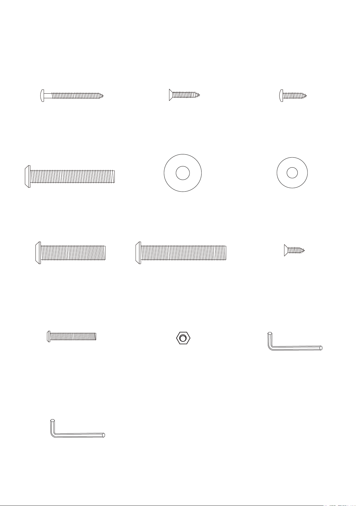
HARDWARE IDENTIFIER
(To Scale)
H1 - 3.5 mm x 35 mm
Phillips Round
Head Screw
(8 pcs)
H4 - 6 mm x 50 mm
Allen Head Bolt
(8 pcs)
H7 - 8 mm x 38 mm
Allen Head Bolt
(8 pcs)
H2 - 3.5 mm x 18 mm
Phillips Flat
Head Screw
(4 pcs)
H5 - 8.5 mm x 22 mm
Flat Washer
(16 pcs)
H8 - 8 mm x 50 mm
Allen Head Bolt
(8 pcs)
H3 - 3.5 mm x 14 mm
Phillips Round
Head Screw
(8 pcs)
H6 - 6.5 mm x 16 mm
Flat Washer
(8 pcs)
H9 - 3.5 mm x 12 mm
Phillips Flat
Head Screw
(4 pcs)
H10 -
Round Head Bolt
All Rights Reserved.
©
2017 Escalade Sports
M4 x 27 mm Phillips
T2 - M5 Allen Wrench
(26 pcs)
(Not to Scale)
(1 pc)
H11 - M4 Nylock Locknut
(26 pcs)
3
(Not to Scale)
T1 - M4
For Customer Service Call 1-888-996-2729
Allen Wrench
(1 pc)
Page 4
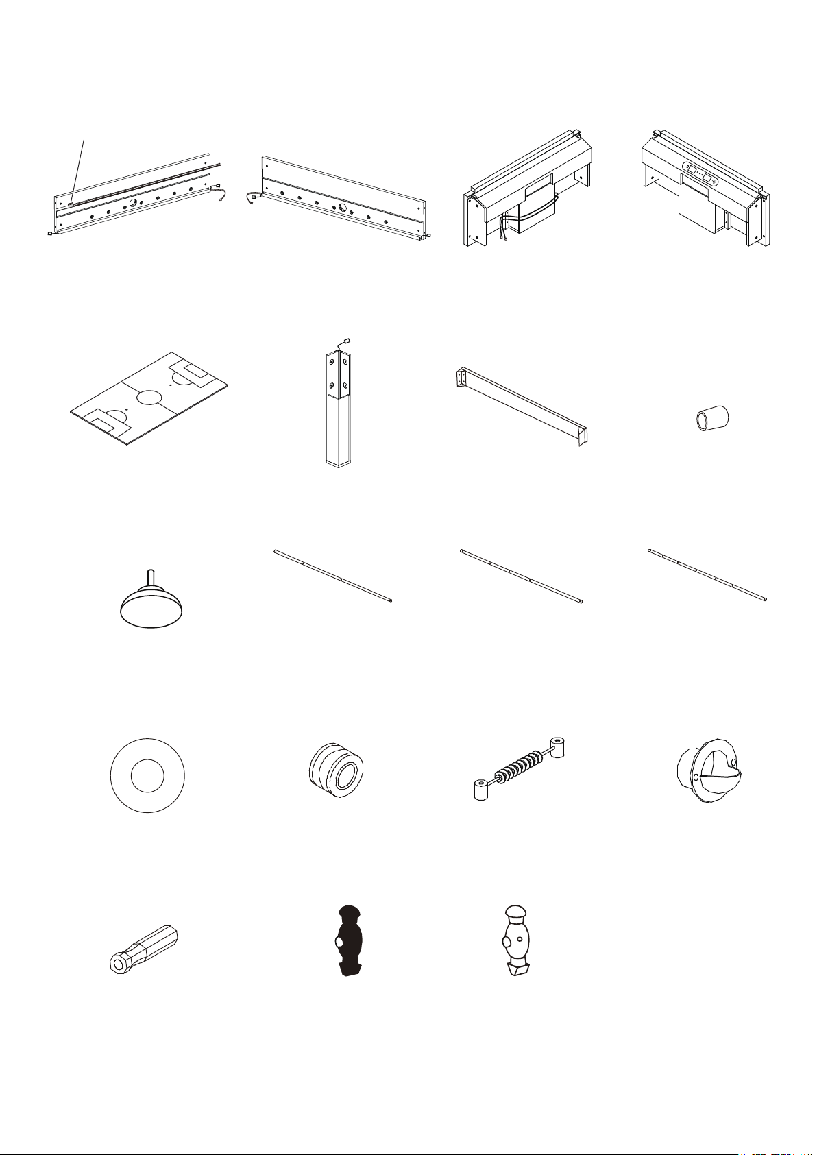
C6 Connecting Module
P1R - Side Apron-A with C6
Connecting Module Attached
(1 pc)
PARTS IDENTIFIER
(Not to Scale)
P2R - Side Apron-B
P3R- End Apron-A
(1 pc)(1 pc)
P4R
- End Apron-B with
Electronic Scorer &
C1 Junction Box Attached
(1 pc)
P5 - Playfield
(1 pc)
P9 - Leg Leveler
(4 pcs)
P13 - Plastic Rod Washer
(16 pcs)
P6R - Leg with LED
wire connection
(4 pcs)
P10 - 2-Hole
Players Rod
(2 pcs) (4 pcs) (2 pcs)
P14 - Rubber Rod Bumper
(16 pcs)
P7 - Playfield Support Brace
with Brackets attached
(2 pcs)
P11 - 3-Hole
Players Rod
P15 - Manual
Scorer (2 pcs)
P8 - Player Rod
End Cap
(8 pcs)
P12 - 5-Hole
Players Rod
P16 - Ball Entry
Cup (2 pcs)
P17 - Player Rod Handle
(8 pcs)
All Rights Reserved.
©
2017 Escalade Sports
P18 - Blue Player
(13 pcs)
P19 - Ivory Player
(13 pcs)
4
For Customer Service Call 1-888-996-2729
Page 5
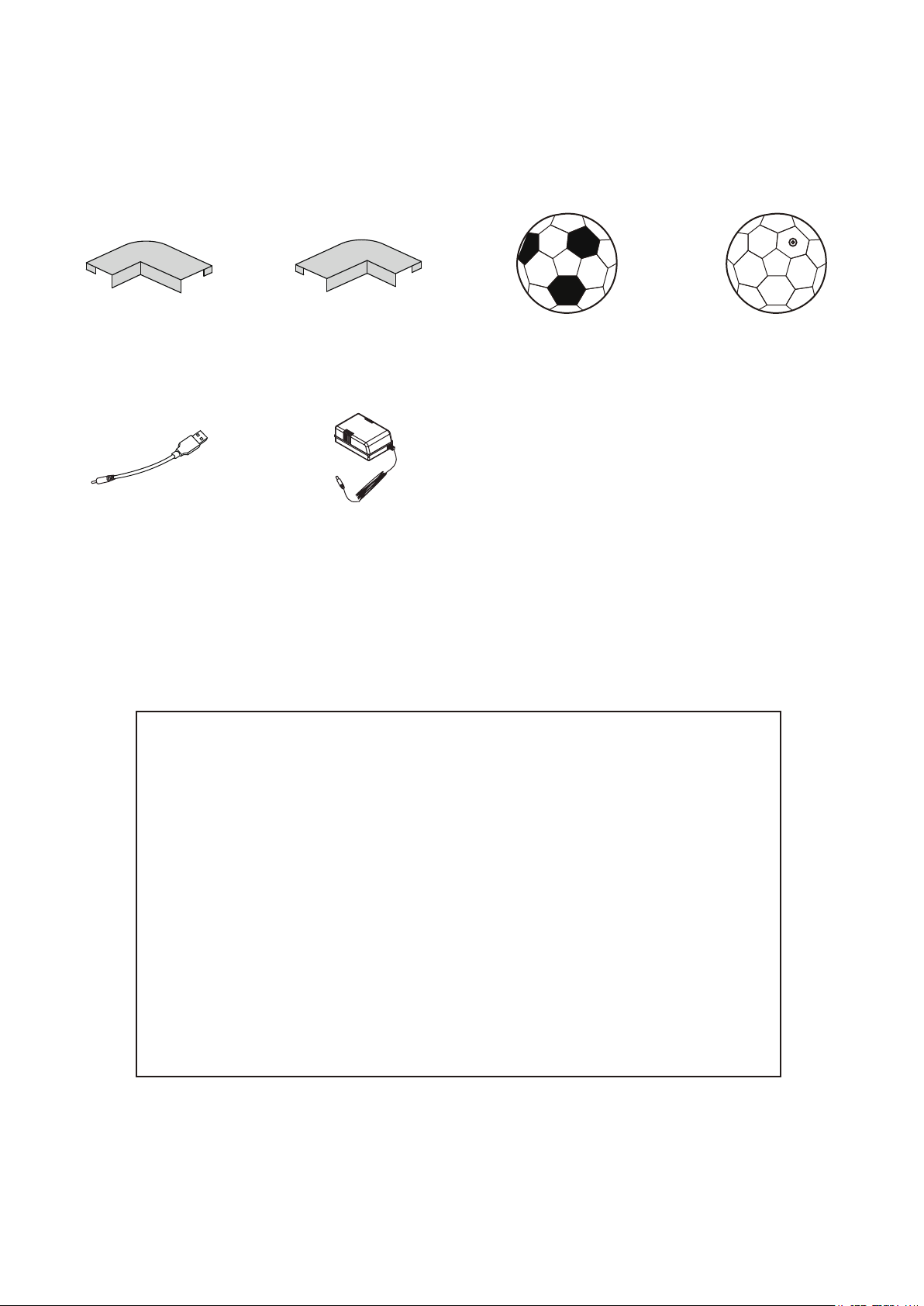
PARTS IDENTIFIER
(Not to Scale)
P21 - Left Corner Cap
(2 pcs)
(Used to charge A2
LED Soccer Ball only)
A3 - USB Cable
Packed with A2 LED Soccer Ball
(1 pc)
Note: This equipment has been tested and found to comply with the limits for a Class B digital device,
pursuant to part 15 of the FCC Rules. These limits are designed to provide reasonable protection against
harmful interference in a residential installation. This equipment generates, uses and can radiate radio
frequency energy and, if not installed and used in accordance with the instructions, may cause harmful
interference to radio communications. However, there is no guarantee that interference will not occur in
a particular installation. If this equipment does cause harmful interference to radio or television reception,
which can be determined by turning the equipment off and on, the user is encouraged to try to correct the
interference by one or more of the following measures:
- Reorient or relocate the receiving antenna.
- Increase the separation between the equipment and receiver.
- Connect the equipment into an outlet on a circuit different from that to which the receiver is connected.
- Consult the dealer or an experienced radio/TV technician for help.
P22 - Right Corner Cap
(2 pcs)
A4 - A/C Adapter
(1 pc)
A1- Soccer Ball
(2 pcs)
A2- Rechargeable
LED Soccer Ball
(1 pc)
All Rights Reserved.
©
2017 Escalade Sports
This device complies with part 15 of the FCC Rules. Operation is subject to the following two conditions:
(1) This device may not cause harmful interference, and (2) this device must accept any interference
received, including interference that may cause undesired operation."
"CAUTION: Changes or modifications not expressly approved by the party responsible for compliance
could void the user's authority to operate the equipment."
5
For Customer Service Call 1-888-996-2729
Page 6

Assembly Instructions
SPECIAL NOTES - ASSEMBLY OF THIS FOOSBALL TABLE:
1. It will be helpful to build this table on 2 saw horses or on a work table.
It is suggested to build this table on the carton or other protective material as to not
scratch or blemish any parts .
2. We highly recommend a 2nd adult to help during the assembly process.
3. The "LED" features of this table requires the wires to be placed and routed correctly
during the assembly process to insure correct connection points in the latter assembly.
Please read the text closely and study the diagrams and notes to insure correct assembly.
4. Please handle all wires with care - do not pull on, trap wires under washers or other
parts, or damage the connectors.
Make sure to place the wires exactly where the text, notes and diagrams say to place them.
5. The male and female connectors will only connect ONE WAY.
Please study the diagrams and study the connectors before connecting.
Do not force connections.
6. When table assembly is complete - gently push in or together on all connections to
insure a good connection.
7. The "BLACK and RED" wire will appear in each of the 4 corners ( bottom , during upside
down assembly ).
These are for the leg LED's, and will connect latter in the assembly.
All Rights Reserved.
©
2017 Escalade Sports
6
For Customer Service Call 1-888-996-2729
Page 7
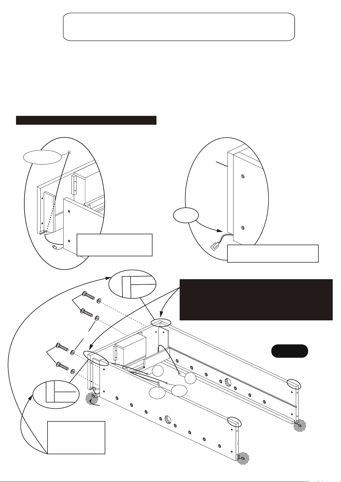
PARTS REQUIRED:
1
1
1 pc - P4R End Apron- B1 pc - P1R Side Apron- A
4 pcs - H4 6 mm x 50 mm Allen Head Bolt 4 pcs - H6 6.5 mm x 16 mm Flat Washer
1 pc - P2R Side Apron- B
STEP 1
Find a clean, level place to begin the assembly of your soccer table. We recommend
building the table on the box top to protect the parts during assembly.
It is very important to assemble table on a level and flat surface. This will keep the
end aprons and side aprons “FLUSH” on the top and bottom edges.
Attach P1R Side Apron-A and P2R Side Apron-B onto P4R End Apron-B using countersunk holes
with H4 Bolts and H6 Washers by T1 Allen Wrench as shown in FIGURE 1.
Do not tighten H4 Bolts until STEP 3 is completed.
Do not connect any wires at this time.
C3 or C7
H4
P4R
P1R
or P2R
Feed C3 and C7 wires through
the hole on the P4 End Apron
before installing aprons
2
2
P4R
P1R
Cut-out
NOTE: Both P1 Rand P2R Side Aprons and P4R End Apron
must be square and flush in the corners.
H4 bolts thread into barrel nuts located inside of the side
aprons. Should the H4 bolts not want to "start" - look
inside the hole as it may be necessary to slightly adjust the
2
2
position of the barrel nut in order for the H4 bolt to start.
or P2R
Leave these red and black wires in the
cut-out, and outside of P4 End Apron
H4
NOTE :Use the 1-1,2-2,
3-3,4-4 – numbers on
the bottom corner of
each apron to correctly
orientate the 4 aprons.
All Rights Reserved.
©
2017 Escalade Sports
H6
1
1
P4R
FIGURE 1
P2R
C3
C7
4
1
1
Red and Black wires outside
C6-A
C6-B
P1R
3
Outside
Outside
7
For Customer Service Call 1-888-996-2729
Page 8
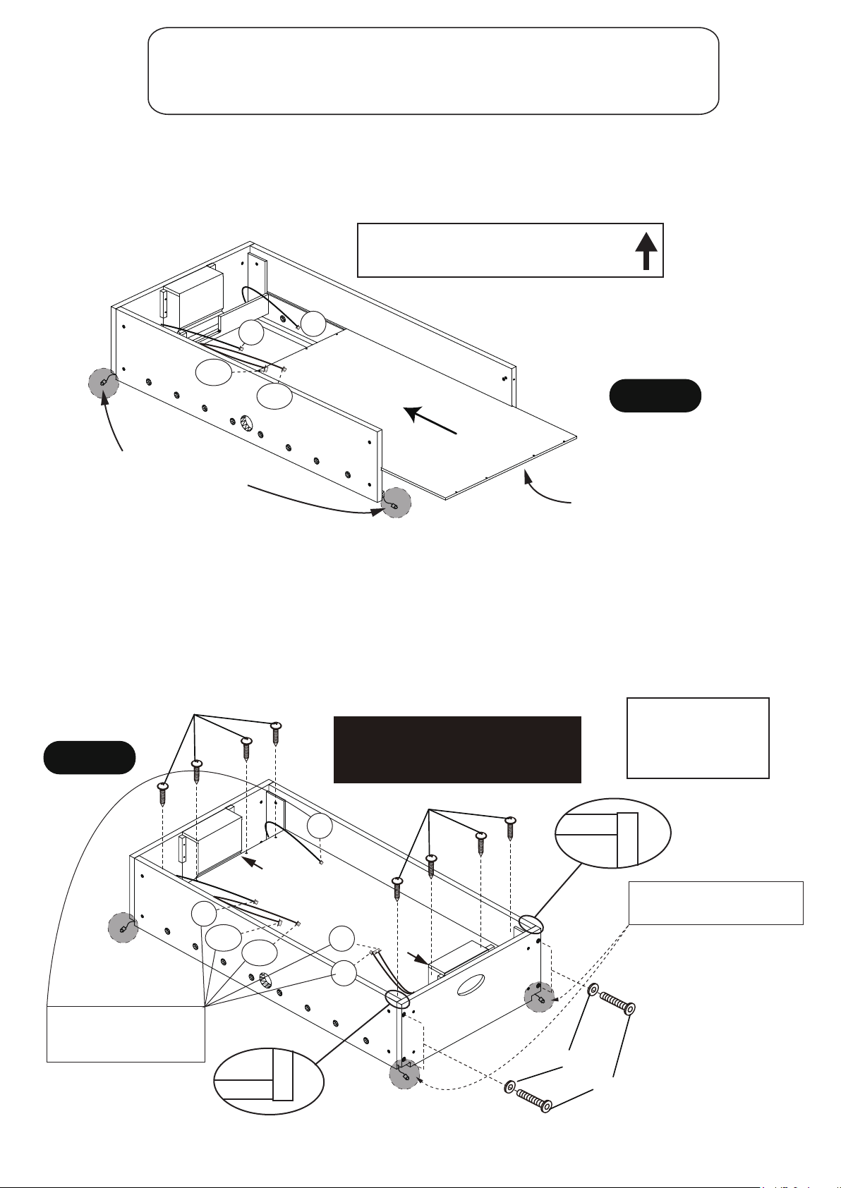
PARTS REQUIRED:
4 pcs - H4 6 mm x 50 mm Allen Head Bolt 4 pcs - H6 6.5 mm x 16 mm Flat Washer
8 pcs - H1 3.5 mm x 35 mm Phillips Round Head Screw
1 pc - P5 Playfield1 pc - P3R End Apron- A
STEP 2
Then slide the P5 Playfield with the graphic facing down into the grooves of P1R and P2R Side
Aprons as shown in FIGURE 2.
NOTE: C3, C6-A, C6-B and C7 wires
all stay ABOVE playfield.
C3
C6-A
C6-B
C7
P2R
P5
FIGURE 2
P1R
Black and Red wires in
this correct position for
future leg assembly.
NOTE:
Playfield Graphic on
the underside facing the floor
STEP 3
Attach P3R End Apron-A onto P1R Side Apron-A and P2R Side Apron-B using H4 Bolts and
H6 Washers as shown in FIGURE 3.
Use T1 Allen Wrench to tighten all H4 Bolts in STEP 1 and STEP 3 now.
Center and attach P5 Playfield in the cabinet using pre-driled holes with H1 Screws as shown
in FIGURE 3.
Tighten, but do not strip out H1 Screws.
NOTE :Use the 1-1,2-2,
3-3,4-4 – numbers on
the bottom corner of
each apron to correctly
orientate the 4 aprons.
FIGURE 3
H1
IMPORTANT NOTE:
Please be sure to install H1 Screws
exactly as per FIGURE 3.
Screws must be screwed straight down.
Outside
Leave C3, C6-A, C6-B, C7
C8 and C9 wires inside of
aprons and above playfield
All Rights Reserved.
©
2017 Escalade Sports
P1R
P4R
C3
C6-A
C7
P5 PLAYFIELD MUST BE CENTERED
BEFORE INSTALLING H1 SCREWS
P2R
C9
C6-B
C8
3
3
Outside
H1
4
4
3
3
P3R
Outside
4
4
Leave the red and black wires
in the cut out of P3R End Apron
H6
H4
8
For Customer Service Call 1-888-996-2729
Page 9
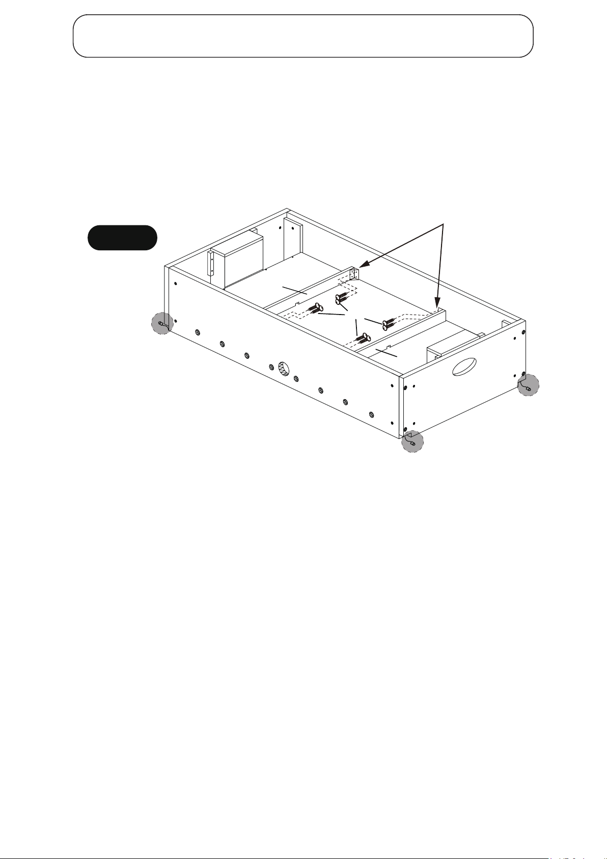
PARTS REQUIRED:
2 pcs - P7 Playfield Support Brace
8 pcs - H3 3.5 mm x 14 mm Phillips Round Head Screw
STEP 4
Attach P7 Playfield Support Braces onto P1R and P2R Side Aprons using pilot holes with H3 Screws
as shown in FIGURE 4.
Tighten, but do not strip out H3 Screws.
Pilot holes
FIGURE 4
Outside
P7
P2R
H3
P1R
P7
Outside
Outside
STEP 5
Connect LED Goal Trim, LED Rail Light, Scoring Sensor to Junction box and Connecting Wire
as per the ELECTRICAL CONNECTIONS & SPARE PARTS DRAWINGS on the next page.
All Rights Reserved.
©
2017 Escalade Sports
9
For Customer Service Call 1-888-996-2729
Page 10
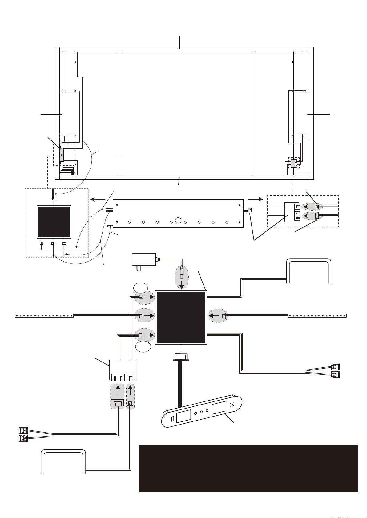
ELECTRICAL CONNECTIONS & SPARE PARTS DRAWINGS
P2R
P4R
C1- Junction Box
C2C7C4
POWER
2 4
C7 Wire
1 2
1
C6-B Wire
P1R
Outside of P1R Side Apron
G01344
C5
C6-AC6-B C3
C3- LED Rail Lights-A wire
C6- Connecting Module
A4- A/C Adapter
4
P3R
3
3
C8- LED Goal Trim-B
C9- Scoring Sensor-B
C6-A Wire
C6-B
POWER
C1- Junction Box
C2C7C4
G01344
C2- LED Goal Trim-A
(Already connected)
C3- LED Rail Lights-A C7- LED Rail Lights-B
C6-AC6-B C3
C5
C6-A
C6- Connecting Module`
C9- Scoring Sensor-B
C4- Scoring Sensor-A
(Already connected)
C5- Electronic Scorer
(Already connected)
C8- LED Goal Trim-B
All Rights Reserved.
©
2017 Escalade Sports
NOTE: lightly push in on all connections to insure good connections.
All male to female connectors will only connect one way depending
on the tabs and slots of each.
Please closely inspect both the male and female connectors
to determine how to correctly plug the two together
10
For Customer Service Call 1-888-996-2729
Page 11
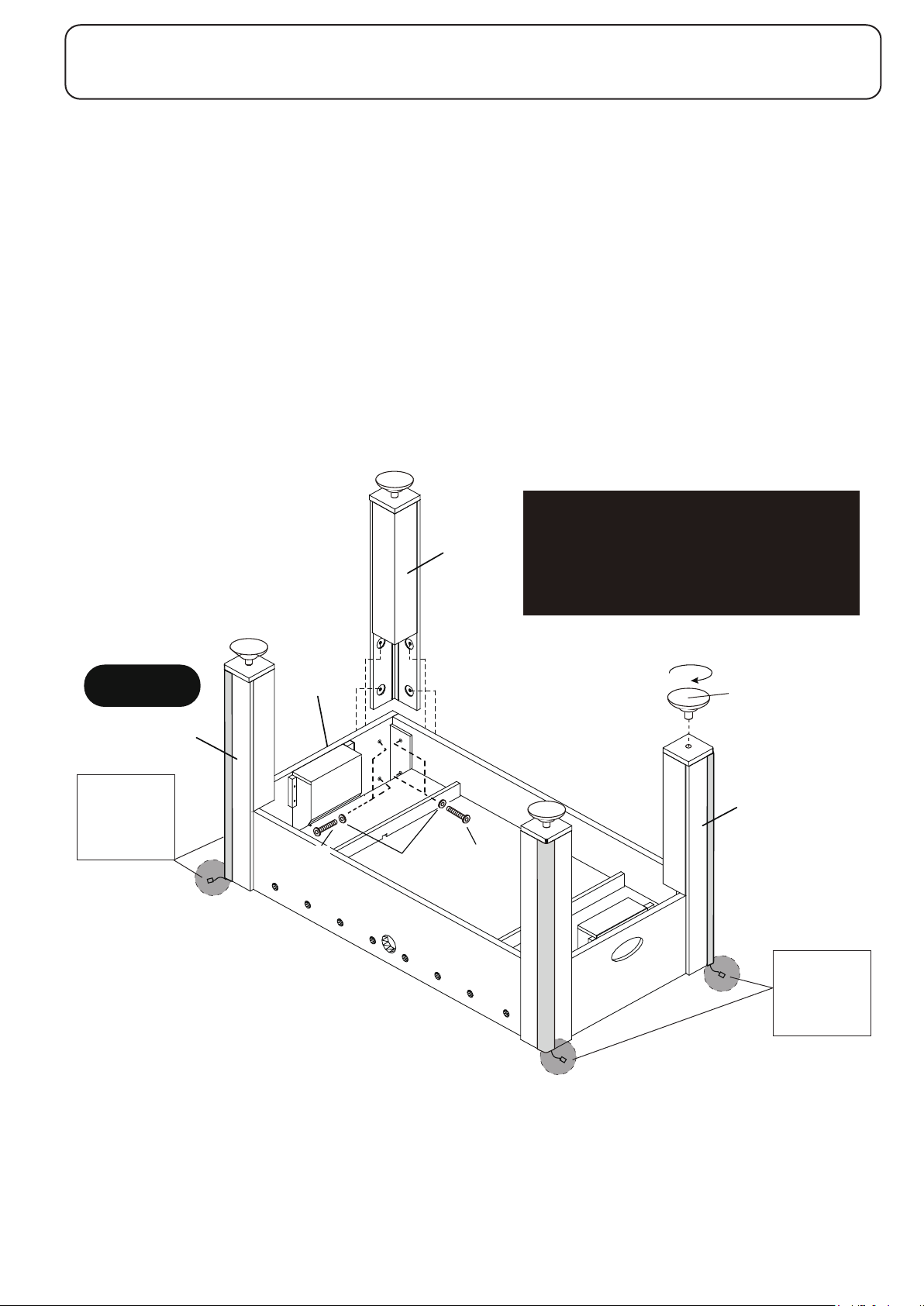
PARTS REQUIRED:
4 pcs - P6R Leg with LED wire connection
4 pcs - P9 Leg Leveler8 pcs - H7 8 mm x 38 mm Allen Head Bolt
16 pcs - H5 8.5 mm x 22 mm Flat Washer
8 pcs - H8 8 mm x 50 mm Allen Head Bolt
STEP 6
Attach P6-R Legs onto P1R, P2R Side Aprons and P3R, P4R End Aprons using H7,H8 Bolts
and H5 washers as shown in FIGURE 6. Use T2 Allen Wrench to tighten all P6R Legs.
Then screw P9 Leg Levelers into the bottom of each leg as shown in FIGURE 6.
FIGURE 6
P6R
Leave the
red and black
wires of every
Leg outside
P4R
H8
H5
P1R
P6R
H7
IMPORTANT NOTE:
The longer H8 Bolts are used to screw
into the Side Aprons.
The shorter H7 Bolts are used to screw
into the End Aprons.
P9
P2
P6R
P6R
Leave the
P3R
red and black
wires of every
Leg outside
All Rights Reserved.
©
2017 Escalade Sports
11
For Customer Service Call 1-888-996-2729
Page 12
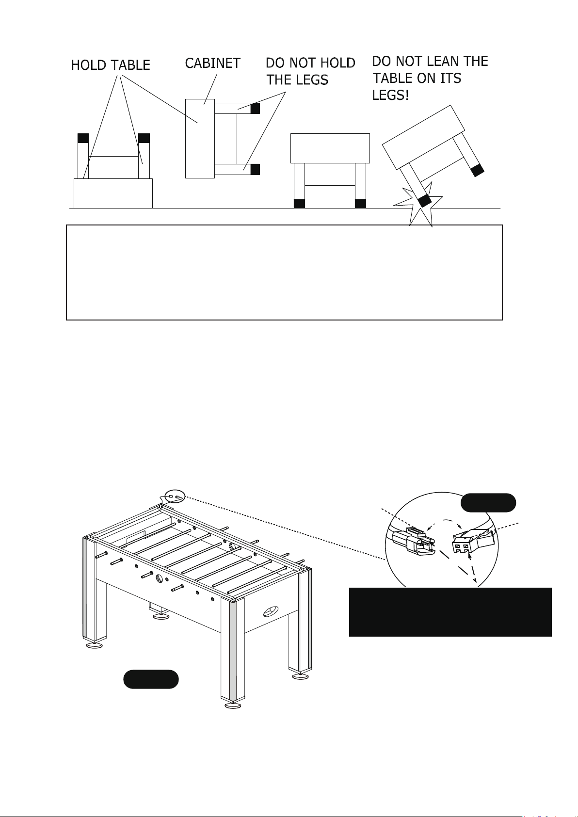
CAUTION: Four strong adults are recommended to flip
the table as shown.
1. Grab the table on the ground.
2. Turn the table over.
3. Place it on all four feet at the same time on the ground.
STEP 7
Connect the female plug of each leg to the male plug near apron corners, and carefully stow wires
into the corner as shown in
FIGURE 7 and Detail B.
P11
All Rights Reserved.
©
2017 Escalade Sports
FIGURE 7
P11
P12
P10
12
P11
Snap Lock
NOTE:Make sure slots on plugs are turned correctly
for correct installation.DO NOT FORCE THIS
CONNECTION and a flashlight will be very helpful to
study both the male plug and female Plug to insure
a correct connection.
For Customer Service Call 1-888-996-2729
Detail B
Tab for
Snap Lock
Page 13
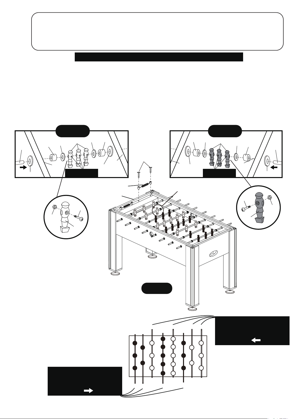
PARTS REQUIRED:
2 pcs - P15 Manual Scorer
4 pcs - P11 3-Player Rod
2 pcs - P10 2-Player Rod
16 pcs - P13 Plastic Rod Washer 4 pcs - H2
26 pcs - H10 M4 x 27 mm Bolt
26 pcs - H11 M4 Nylock Locknut
2 pcs - P12 5-Player Rod
13 pcs - P19 Ivory Player
16 pcs - P14 Rubber Rod Bumper
3.5 mm x 18 mm Phillips Flat Head Screw
13 pcs - P18 Blue Player
STEP 8
NOTE: STUDY DIAGRAM CLOSELY FOR CORRECT PLAYER PLACEMENT
Slide P10 2-Player Rod, P11 3-Player Rods and P12 5-Player Rod through Rod Bushings of P2 Side Apron-B,
P14 Rod Bumper, P13 Plastic Rod Washer, P18 Blue Players or P19 Ivory Players, P13 Rod Washer, P14
Rubber Rod Bumper and P1 Side Apron-A as shown in FIGURE 8, DETAIL B and DETAIL C.
NOTE: Please note the location of the hole or indentation that is near one end of each rod. This is the
handle end of the rod.
Secure P18 Blue Players and P19 Ivory Players onto rods using H10 Bolts and H11 Locknuts as shown.
Attach P15 Manual Scorers using H2 Screws as shown in FIGURE 8.
Tighten, but do not strip out H2 Screws.
DETAIL C
P13
P18
NOTE: Round for Bolt
Head face this side.
P13
P2
P14
P11
Rod Bushing
P11
Rod Bushing
P14
DETAIL B
P13
P2
NOTE: Round for Bolt
Head face this side.
P19
P13
P14
Rod
Bushing
P1
H2
P1
P14
Rod
Bushing
P15
P3R
H10
H10
H11
H11
P19
FIGURE 8
P11 P12
P10 P11
P18
P4R
HOLE OR DIMPLE AT THE END OF ROD
DESIGNATES HANDLE LOCATION.
INSTALL PLAYERS SO H10 BOLT
HEADS ALL FACE
All Rights Reserved.
©
2017 Escalade Sports
HOLE OR DIMPLE AT THE END OF ROD
DESIGNATES HANDLE LOCATION.
INSTALL PLAYERS SO H10 BOLT
HEADS ALL FACE
13
P12
P11P11 P10
For Customer Service Call 1-888-996-2729
Page 14
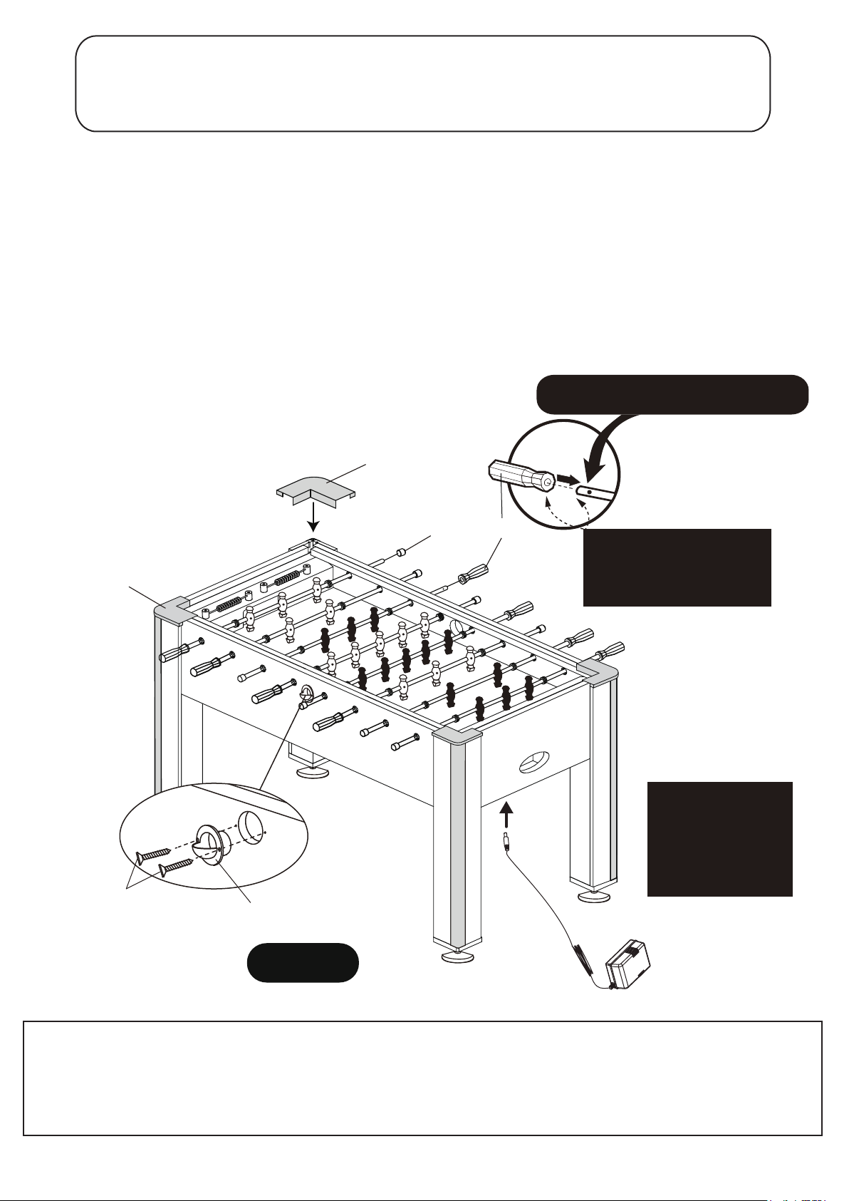
PARTS REQUIRED:
4 pcs - H9 3.5 mm x 12mm Phillips Flat Head Screw
8 pcs - P8 Rod End Cap
2 pcs - P22 Right Corner Cap
8 pcs - P17 Player Rod Handle
2 pcs - P16 Ball Entry Cup
2 pcs - P21 Left Corner Cap
STEP 9
Insert the P17 Rod Handles onto the rods end with the hole.
Attach P8 Rod End Caps to the rods as shown in FIGURE 9.
Attach P16 Ball Entry Cups on Side Aprons using pilot holes with H9 Screws.
Tighten, but do not strip out H9 Screws.
Carefully peel paper protective coating from adhesive strips from the back of P11 Corner Caps
to reveal adhesive strips.
Attach P21 Left corner Caps P22 Right corner Caps to the table corners as shown in FIGURE 9.
Connect A4 A/C Adapter to C1 Junction box attached in the P4 End Apron - B. You can see
the ELECTRICAL CONNECTIONS & SPARE PARTS DRAWINGS in Page 10 for reference.
NOTE: Rod Handle should be placed on
rod end WITH THE HOLE OR DIMPLE
P21
P22
H9
P16
P17P8
NOTE: A small amount of
liquid soap will greatly help
installing the P17 Rod
Handle onto the player rods.
P4R
Please take special
consideration as
to the location of this
table as to not allow
the A/C adaptor cord
to be a trip hazard.
A4- A/C Adapter
FIGURE 9
Note : All LED components of this table have been factory tested. Should some or all of the LED
components and scoring not operate properly, carefully inspect that all connections are made
into the correct port - and lightly push in on all connections to insure a good connection.
Also , make sure the A/C adaptor is plugged into the C1 junction box correctly .
Also , make sure your wall outlet is a live socket .
All Rights Reserved.
©
2017 Escalade Sports
14
For Customer Service Call 1-888-996-2729
Page 15
Congratulations! You have now assembled your soccer table. Please note the Care and Use
instructions below to insure many years of trouble free use of your soccer table.
CARE AND USE OF YOUR LED AZURE SOCCER TABLE
1. Apply a few drops of lubricant (not provided) to the rods and the bushings.
Rotate rods to make sure you spread lubricant evenly.
2. Use spray furniture polish to clean all exterior surfaces of your soccer table.
3. Use a carpenters level to properly level table using the leg levelers.
4. This product is intended for INDOOR use only.
5. DO NOT sit, climb or lean on the table.
6. DO NOT drag the table when moving it. This will damage the legs.
7. DO NOT set drinks on the table.
8. Table LED’s and scoring will automatically turn off after a few minutes of non-play.
PRODUCT PARTS LIST FOR MODEL # G01344
Key # Part #
H1
H2
H3
H4
H5
H6
H7
H8
H9
H10
H11
T1
T2
P1R
P2R
P3R
P4R
P5
P6R
P7
P8
P9
P10
P11
P12
P13
P14
P15
P16
P17
P18
P19
P21
P22
A1
A2
A3
A4
C1
C2
C3
C4
C5
C6
C7
C8
C9
K1
M1
G01344HLH1
G01344HLH2
G01344HLH3
G01344HLH4
G01344HLH5
G01344HLH6
G01344HLH7
G01344HLH8
G01344HLH9
G01344HLH10
G01344HLH11
G01344HLT1
G01344HLT2
G01344HLP1R
G01344HLP2R
G01344HLP3R
G01344HLP4R
G01344HLP5
G01344HLP6R
G01344HLP7
G01344HLP8
G01344HLP9
G01344HLP10
G01344HLP11
G01344HLP12
G01344HLP13
G01344HLP14
G01344HLP15
G01344HLP16
G01344HLP17
G01344HLP18
G01344HLP19
G01344HLP21
G01344HLP22
G01344HLA1
G01344HLA2
G01344HLA3
G01344HLA4
G01344HLC1
G01344HLC2
G01344HLC3
G01344HLC4
G01344HLC5
G01344HLC6
G01344HLC7
G01344HLC8
G01344HLC9
G01344HLK1
G01344HLM1
3.5 mm x 35 mm Phillips Round Head Screw
3.5 mm x 18 mm Phillips Flat Head Screw
3.5 mm x 14 mm Phillips Round Head Screw
6 mm x 50 mm Allen Head Bolt
8.5 mm x 22 mm Flat Washer
6.5 mm x 16 mm Flat Washer
8 mm x 38 mm Allen Head Bolt
8 mm x 50 mm Allen Head Bolt
3.5 mm x 12 mm Phillips Flat Head Screw
M4 x 27 mm Phillips Round Head Bolt
M4 Nylock Locknut
M4 Allen Wrench
M5 Allen Wrench
Side Apron- A with C6 Connection Module attached
Side Apron- B
End Apron- A
End Apron- B with Electronic Scorer & C1 Junction Box Attached
Playfield
Leg with LED wire connection
Playfield Support Brace with brackets attached
Player Rod End Cap
Leg Leveler
2-Player Rod
3-Player Rod
5-Player Rod
Plastic Rod Washer
Rubber Rod Bumper
Manual Scorer
Ball Entry Cup
Player Rod Handle
Blue Player
Ivory Player
Left Corner Cap
Right Corner Cap
Soccer Ball
Rechargeable LED Soccer Ball
USB Cable
A/C Adapter
Junction Box
LED Goal Trim-A
LED Rail Lights-A
Scoring Sensor-A
Electronic Scorer
Connecting Module
LED Rail Lights-B
LED Goal Trim-B
Scoring Sensor-B
Hardware Kit
Owner’s Manual
Description
Qty.
8
4
8
8
16
8
8
8
4
26
26
1
1
1
1
1
1
1
4
2
8
4
2
4
2
16
16
2
2
8
13
13
2
2
2
1
1
1
1
1
1
1
1
1
1
1
1
1
1
All Rights Reserved.
©
2017 Escalade Sports
15
For Customer Service Call 1-888-996-2729
Page 16
ELECTRONIC SCORER OPERATION:
ON/OFF = Press ON/OFF button to start or turn off the scoring unit.
RESET
SOUND/LED
= Press RESET button to to reset back to the 0:0 score.
= Press SOUND/LED button to turn off the Sound , Press SOUND/LED button again to
turn off the LED lights, Press SOUND/LED button the third time to turn on the Sound
and LED lights.
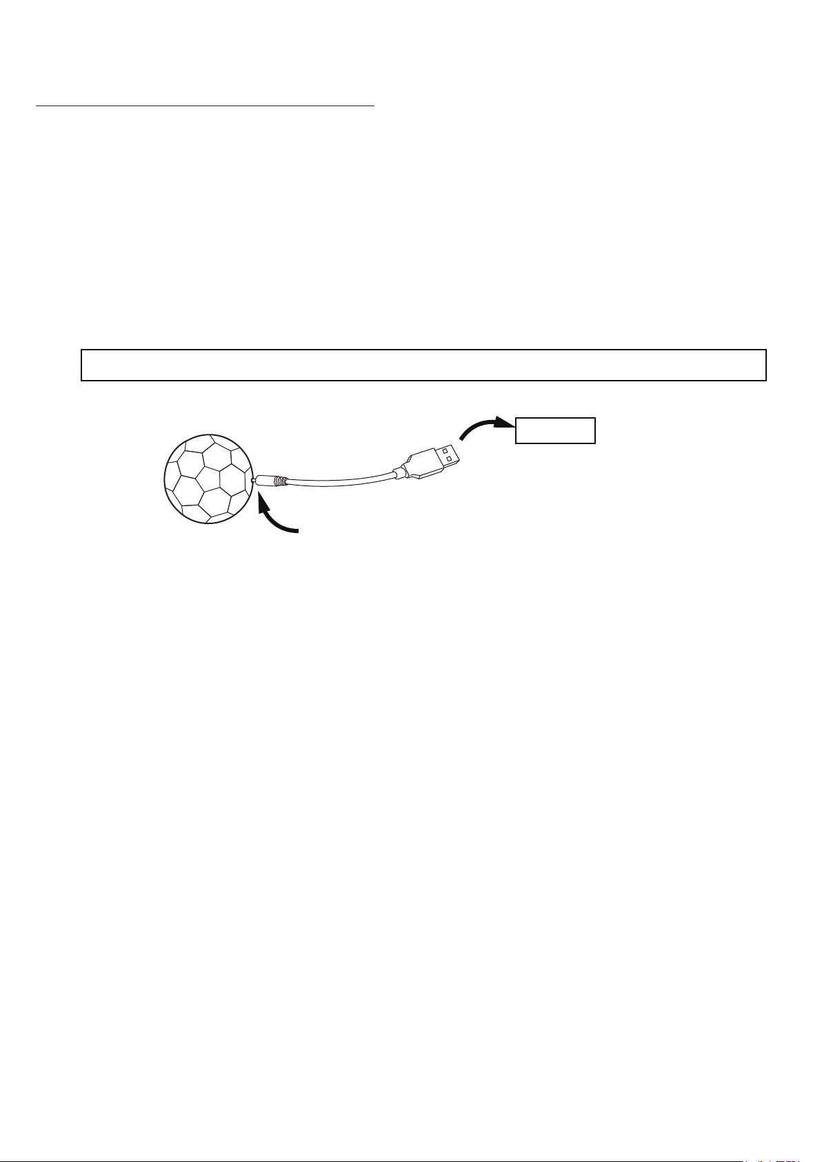
LED BALL BATTERY CHARGE INSTRUCTION
Push charge pin straightly and gently in the LED ball charge hole, DO NOT push hard.
USB Port
Note: Pin will not fully push in to the hole
Stop pushing the pin when it seats into the hole
1. Please charge the ball before First use. Red LED indicator will light up during charging and will
turn off when it is fully charged.
2. You can hit the LED ball onto the playfield to turn on the LED light inside the LED ball, and it
will turn off automatically when it ramains motionless for 60 seconds.
All Rights Reserved.
©
2017 Escalade Sports
16
For Customer Service Call 1-888-996-2729
Page 17

90 DAY LIMITED WARRANTY
This consumer warranty extends to the original consumer purchase of any ESCALADESPORTS
Product (hereinafter referred as the "Product").
WARRANTY DURATION: This Product is warranted to the original consumer purchase of a period of 90 days from the original purchase.
WARRANTY COVERAGE: ESCALADE SPORTS warrants to the original Consumer Purchaser
that any Product of its manufacture is free from defects in material and workmanship when used
for the intended purpose under normal use and conditions. THIS WARRANTY IS VOID IF THE
PRODUCT HAS BEEN DAMAGED BY ACCIDENT, UNREASONABLE USE, NEGLIGENCE,
IMPROPER SERVICE, FAILURE TO FOLLOW INSTRUCTIONS PROVIDED WITH THE PRODUCT OR OTHER CAUSES NOT ARISING OUT OF DEFECTS IN MATERIAL AND WORKMANSHIP.
WARRANTY PERFORMANCE: During the above 90 day warranty period, ESCALADESPORTS
shall repair or replace with a comparable model, and Product, or component thereof, which may
prove defective under normal use and proper care, and which our examination shall disclose to
our satisfaction to be thus defective, please contact our Warranty Dept.
1-888-996-2729 / Warranty Dept.
Or Write us at:
Escalade® Sports, Inc. - P.O. Box 889, Evansville, IN 47706
Attn: Warranty Dept.
Or E-mail us at:
Other than shipping requirements no charge will be made for such repair or replacement of inwarranty Products. ESCALADE SPORTS strongly recommends that the Product is insured for
value prior to mailing.
WARRANTY DISCLAIMERS: ANY IMPLIED WARRANTIES ARISING OUT OF
THIS SALE, INCLUDING BUT NOT LIMITED TO THE IMPLIED WARRANTIES OF
MERCHANTABILITY AND FITNESS FOR A PARTICULAR PURPOSE, ARE LIMITED IN DURATION TO THE ABOVE 90 DAY PERIOD. ESCALADE SPORTS
SHALL NOT BE LIABLE FOR LOSS OF USE OF THE PRODUCT OR OTHER
CONSEQUENTIAL OR INCIDENTAL COSTS, EXPENSES OR DAMAGES INCURRED BY THE CONSUMER OF ANY OTHER USE.
Some states do not allow the exclusion or limitation of implied warranties or consequential or
incidental damages, so the above limitations or exclusions may not apply to you.
LEGAL REMEDIES: This warranty gives you specific legal rights and you may also have other
rights which may vary from state to state.
All Rights Reserved.
©
2017 Escalade Sports
17
For Customer Service Call 1-888-996-2729
 Loading...