

Page 1

1-88 8 -996-2729
F AX : 1-866-873-3531
W e striv e t o ensur e tha t ou r product s ar e o f th e highes t quality
an d fre e o f manufacturin g defect s o r missin g parts . Howev e r ,
yo u hav e an y problem s wit h you r ne w product,
D O NO T RETUR N I T T O TH E S T ORE ,
pleas e contac t u s tol l fre e @:
O r writ e to:
Escal a d e Spor t s
Cust o me r Servi c e Depa r tme n t
P .O . Bo x 8 8 9
Evansvill e I N 47706
Y ou r Mode l Numbe r
G04865W
hav e you r mode l numbe r whe n inquirin g abou t parts.
Please
Dat e Cod e
2 - G04865W - - HL
Whe n contactin g Escalad e Sport s pleas e provid e you r mode l numbe r , d at e
cod e (i f a pplicable ) an d par t n umbe r i f requestin g a replacemen t part . T hes e
number s ar e locate d o n th e product , packaging , an d t hi s owner s m anual .
Purchase Dat e
PLEASE RETAIN THIS INSTRUCTION MANUAL FOR FUTURE REFERENCE
1
Page 2

Make sure you understand the following tips before you begin to assemble your hockey table.
1. Start all bolts by hand before tightening.
2. Some drawings or images in this manual may not look exactly like your product. Please
read and understand the text before starting each assembly step.
FOUR ADULTS ARE REQUIRED TO ASSEMBLE
THIS TOP SHELF 90” AIR HOCKEY TABLE
Assembly Tips
Tools Required:
READ AND FOLLOW ALL ASSEMBLY, OPERATION, AND
SAFETY INSTRUCTIONS CAREFULLY. AT LEAST TWO
ADULTS ARE NEEDED TO PUT THIS HOCKEY TABLE
TOGETHER.
T1 - Allen Wrench (Included)
IMPORTANT! READ EACH STEP
IN THIS MANUAL BEFORE YOU
BEGIN THE ASSEMBLY.
Phillips Screwdriver
Furniture Polish and Cloth
2
Page 3
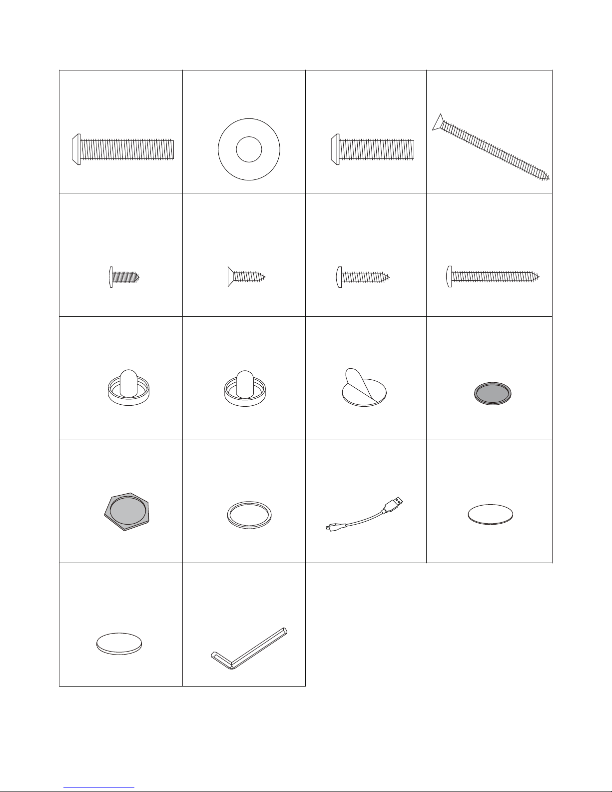
H1 = 28 pcs
H2 = 32 pcs
8.5 mm x 22 mm
8 mm x 35 mm
Allen Head Bolt
Flat Washer
3.5 mm x 12 mm
Phillips Round
Head Screw
H5 = 8 pcs
3.5 mm x 18 mm
Phillips Round
Head Screw
H7 = 2 pcs
3.5 mm x 33 mm
Phillips Round
Head Screw
H8 = 8pcs
4 mm x 45 mm
Phillips Flat
Head Screw
H4 = 16 pcs
T1 = 1 pc
A1 = 1 pc
Red Puck
A6 = 1 pc
USB Cable
1mm Shim Pack
A7 = 1 pc
A8 = 3 pcs
Felt Pad
A3 = 2 pcs
NOTE: A3 Felt Pads may already
Used to level table if required
Used to level table if required
Used to charge A1 and A2
Strikers only
be attached to A1 and A2 Strikers.
H3 = 4 pcs
8 mm x 28 mm
Allen Head Bolt
Allen Wrench
3.5 mm x 14 mm
Phillips Flat
Head Screw
H6 = 2 pcs
Red LED StrikerBlue LED Striker
A2 = 1 pc
Blue LED Puck
A4 = 1 pc
Red LED Puck
A5 = 1 pc
2mm Shim Pack
A9 = 3 pcs
P List
3
Page 4
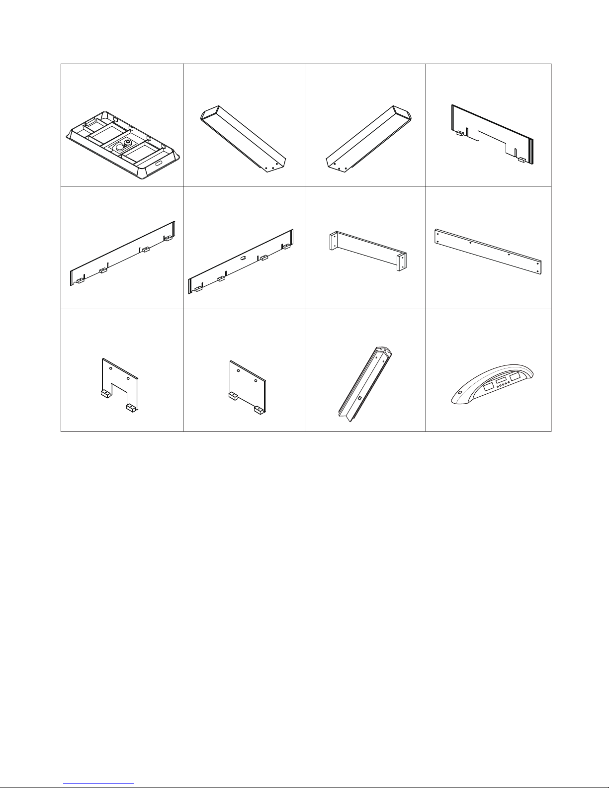
P1 = 1 pc
P2 = 2 pcs
P3 = 2 pcs
Left Leg
Right Leg
Air Hockey
Table Cabinet
P5 = 1 pcs
P6 = 1 pcs
P7 = 2 pcs
End Leg Panel Side Leg Panel
P8 = 2 pcs
End Apron
P9 = 1 pc
Side Apron
Side Leg
Support Board A
Side Leg
Support Board B
P11 = 4 pcs
Corner Post
P4 = 2 pcs
P10 = 1 pc
Side Apron with
ON/OFF Slot
P12 = 1 pc
Scorer Console
s List
4
Page 5
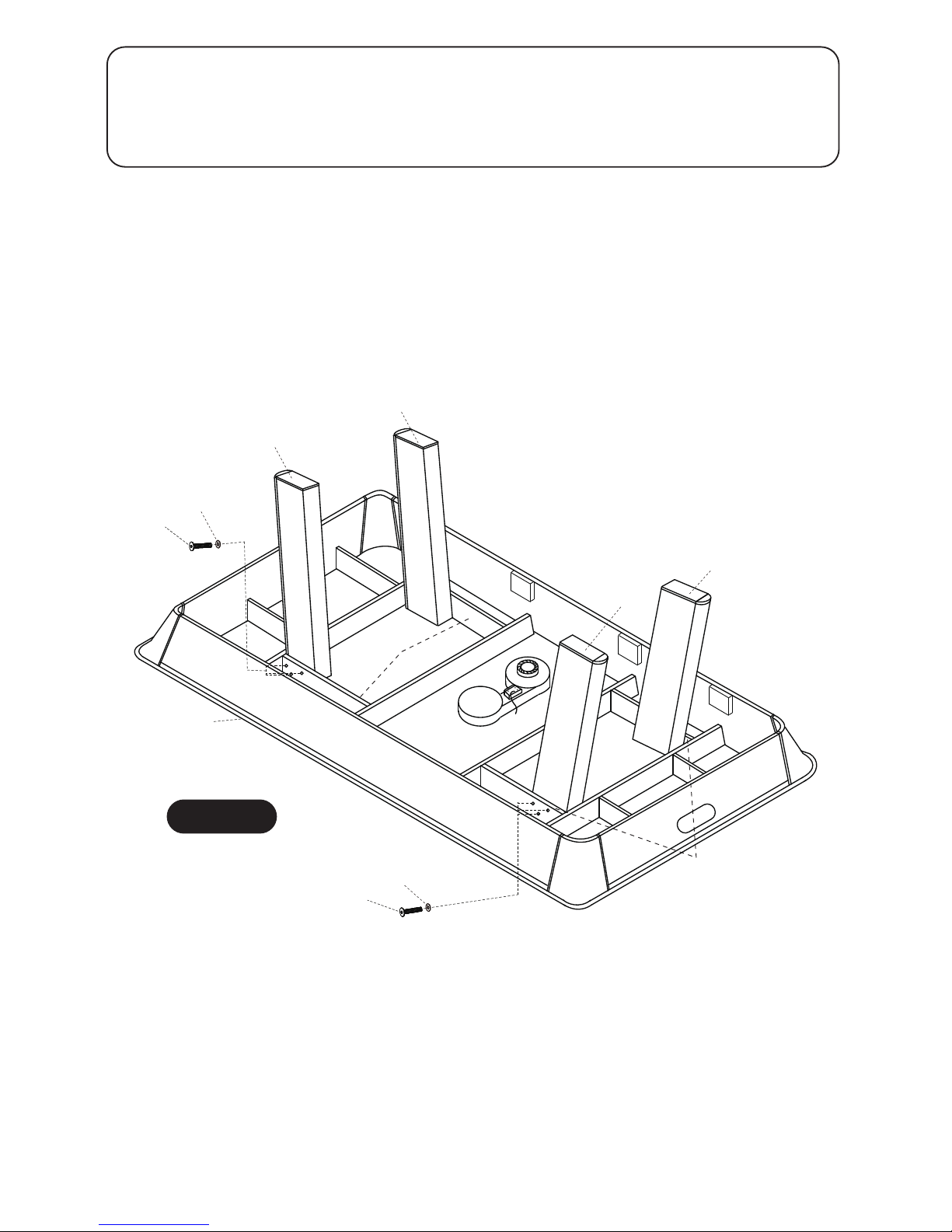
FIGURE 1
1 pc -
P1 Air Hockey Table Cabinet
Support
Beam
Support
Beam
NOTE:BE SURE LEFT LEGS(P2) AND RIGHT
LEGS(P3) ARE INSTALLED INSIDE OF
SUPPORT BEAMS AS PER DIAGRAM
5
STEP:1
Install Left Legs (P2) and Right Legs (P3) onto Air Hockey Table Cabinet (P1) with Allen
Head Bolts (H1) and Flat Washers (H2) using Allen Wrench (T1) as shown in FIGURE 1.
Do not tighten Bolts (H1) at this time.
.
PARTS REQUIRED:
H1 8 x 35mm Allen Head Bolt
12 pcs -
P2 Left Leg2 pcs - P3 Right Leg2 pcs -
H2 8.5 x 22mm Flat Washer12 pcs -
T1 Allen Wrench1 pc -
H1
H2
H1
H2
P2
P2
P1
P3
P3
Leave Air Hockey Table Cabinet (P1) face down in carton to assemble.
Page 6
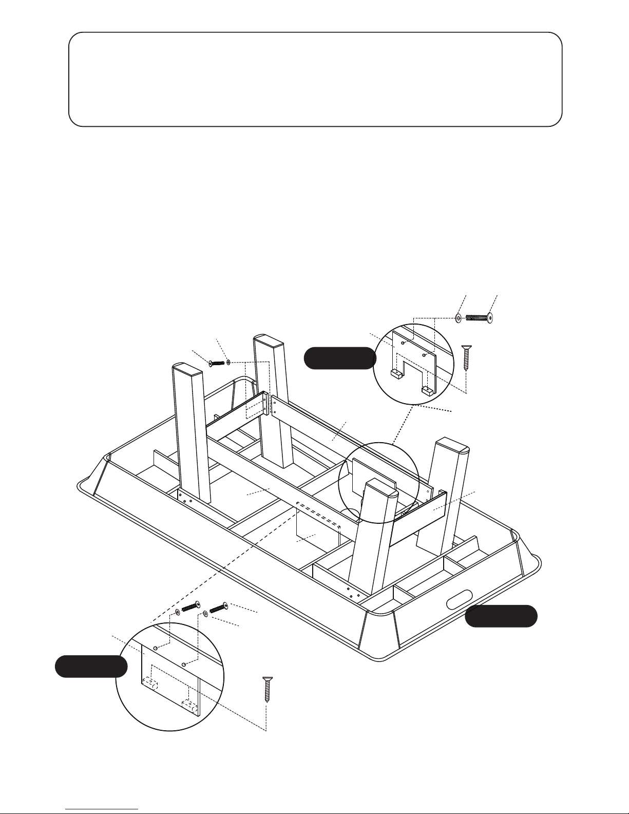
FIGURE 2
6
STEP:2
Install End Leg Panels (P7) and Side Leg Panels (P8) onto the Legs using Bolts (H1) and Flat
Washers (H2) as shown in FIGURE 2
Next, install Side Leg Support Board A (P9) and Side Leg Support Board B (P10) onto inside of
Side Leg Panels (P8) with Bolts (H3) and Flat Washers (H2) using Allen Wrench (T1) as shown
in DETAIL A and DETAIL B.
Next, screw Side Leg Support Board A (P9) and Side Leg Support Board B (P10) to Air Hockey
Table Cabinet (P1) using Screws (H4) as shown in DETAIL A and DETAIL B.
Do not strip out Screws(H4).
Tighten Bolts(H1) from Step 1 at this time.
PARTS REQUIRED:
H1 8 x 35mm Allen Head Bolt 16 pcs -
H4 4 x 45mm Philips Flat Head Screw4 pcs - P7 End Leg Panel2 pcs -
P8 Side Leg Panel2 pcs -
H2 8.5 x 22mm Flat Washer20 pcs -
H3 8 X 28mm Allen Head Bolt
Side Leg Support Board A Side Leg Support Board B
4 pcs -
P91 pc -
P101 pc -
H2
H3
H4
P10
H4
DETAIL B
DETAIL A
H1
H2
H3
H2
P7
P8
P9
P10
P7
P8
NOTE:Side Leg Support Board A(P9) and
Side Leg Support Board B(P10) must fit
inside of Side Leg Panels(P8)
NOTE:This Side Leg
Support Board will
straddle the Air
Blower Fan.
Page 7
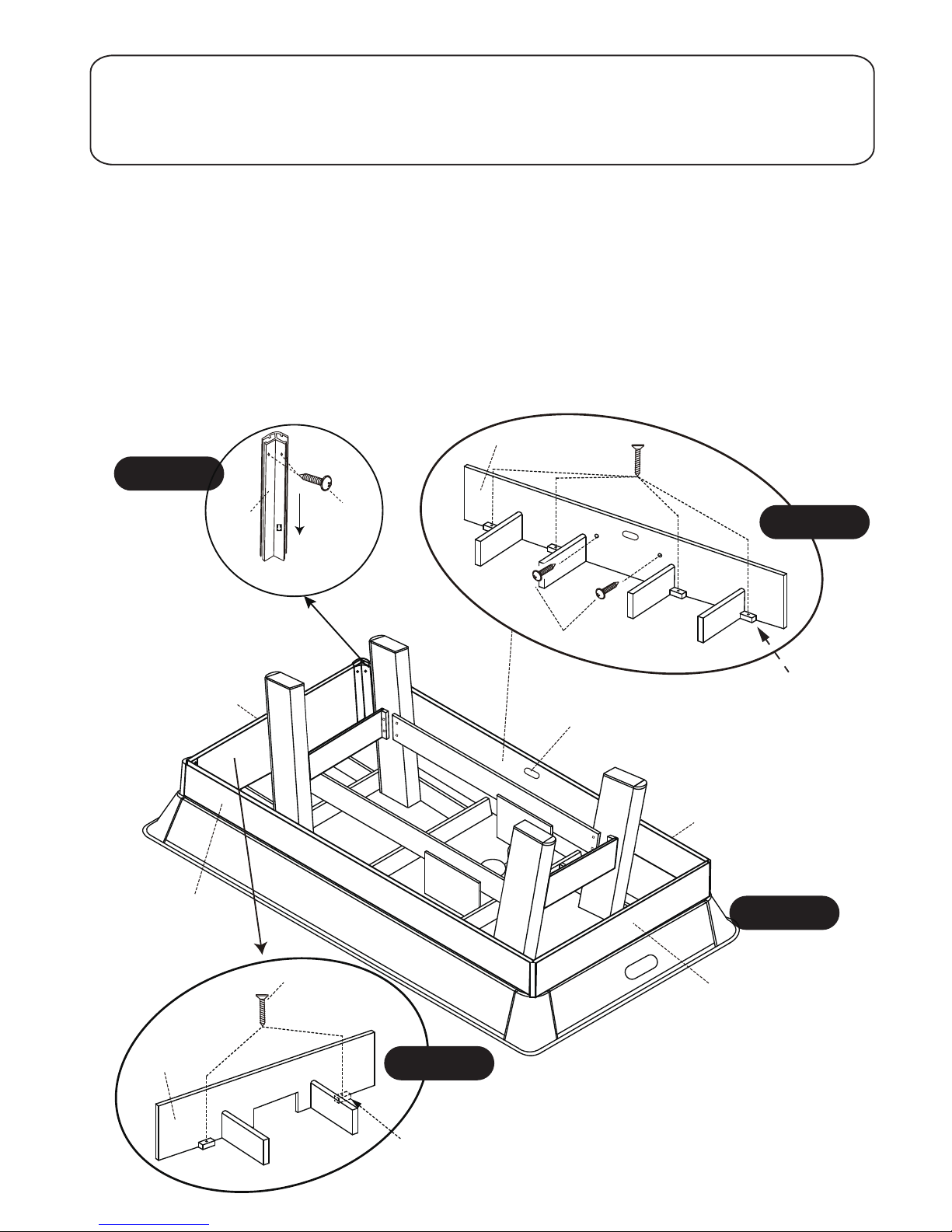
FIGURE 3
NOTE:Side Apron with ON/OFF Slot (P6)
must be on the same side of A/C
Adapter(C2) and ON/OFF Switch(C1)
STEP:3
Next, Attach all apron support blocks to the main cabinet using screws (H4) as per
DETAIL D
and
DETAIL E.
Lastly , install screws (H8) using predrilled holes into side aprons only as shown in
DETAIL D
Tighten, but do not strip out any Screws.
PARTS REQUIRED:
H8
3.5x 33mm Philips Round Head Screw
4 pcs -
H5 3.5 x 12mm Philips Round Head Screw
8 pcs -
H4
4 x 45mm Philips Flat Head Screw
12 pcs -
Apron support block
Apron support block
H4
H8
P6
DETAIL D
DETAIL C
7
Install End Aprons (P4), Side Apron (P5) and Side Apron with ON/OFF Slot (P6) as shown in
FIGURE 3.
Slide Corner Posts (P11) down onto each end of End Aprons and Side Aprons, and attached them
using Screws (H5) as shown in DETAIL C.
H4
H5
P11
P5
P6
P4
P4
P4
DETAIL E
2 pcs - P4 End Apron
1 pc - P6 Side Apron with ON/OFF Slot
1 pc - P5 Side Apron
4 pcs - P11 Corner Post
Page 8
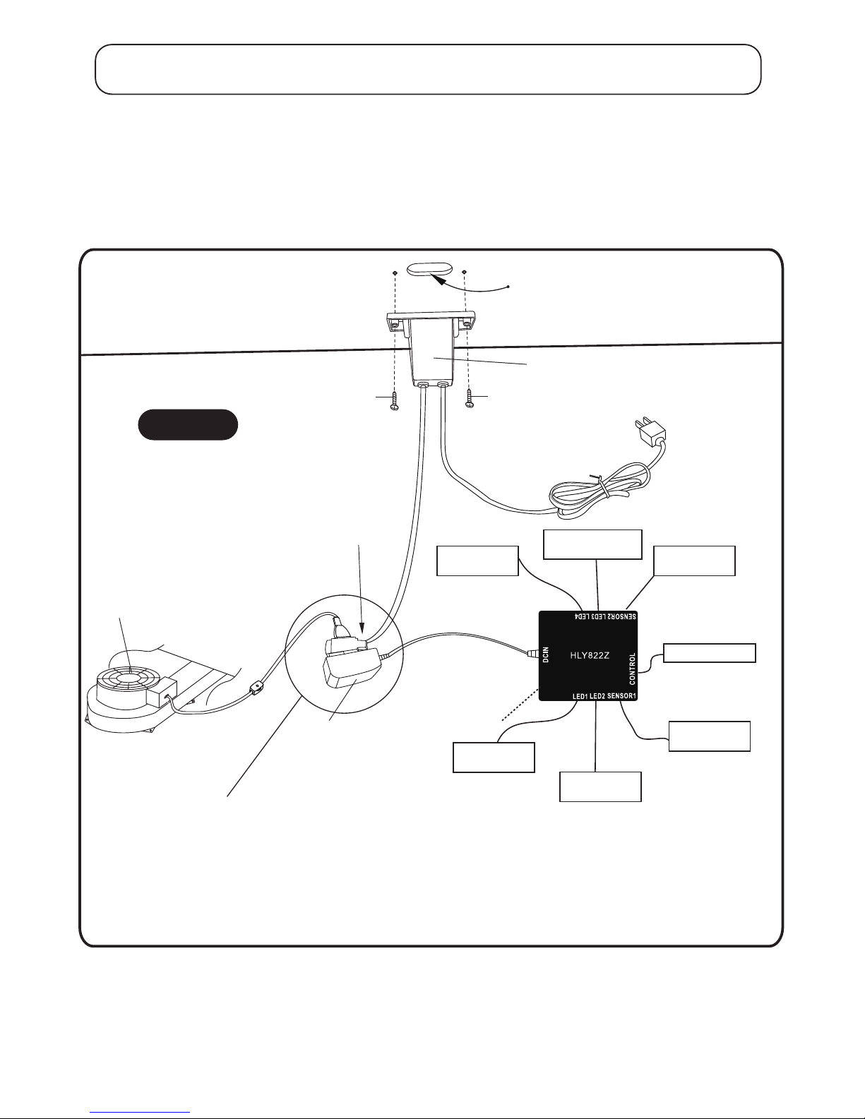
8
NOTE:Double check that
these connections are tight.
NOTE: lightly push in
on all connections to
insure good connections.
H6
H6
P6 Side Apron
with ON/OFF Slot
(non laminated side)
C1- ON/OFF Switch
C2- A/C
Adapter
C3- Junction Box
Air Blower
Female Socket
Plug into wall outlet
Left LED Goal
Left LED Lights
Left Sensor
Electronic Scorer
Right LED Goal
Right LED Lights
Right Sensor
STEP:4
Install ON/OFF Switch (C1) onto inside of Side Apron with ON/OFF Slot (P6) using pre-drilled
holes with Philips Flat Head Screws (H6) as shown in FIGURE 4.
Tighten, but do not strip out Screws (H6).
PARTS REQUIRED:
H6 3.5 x 14mm Philips Flat Head Screw 2 pcs - C1 ON/OFF Switch1 pc -
FIGURE 4
Page 9
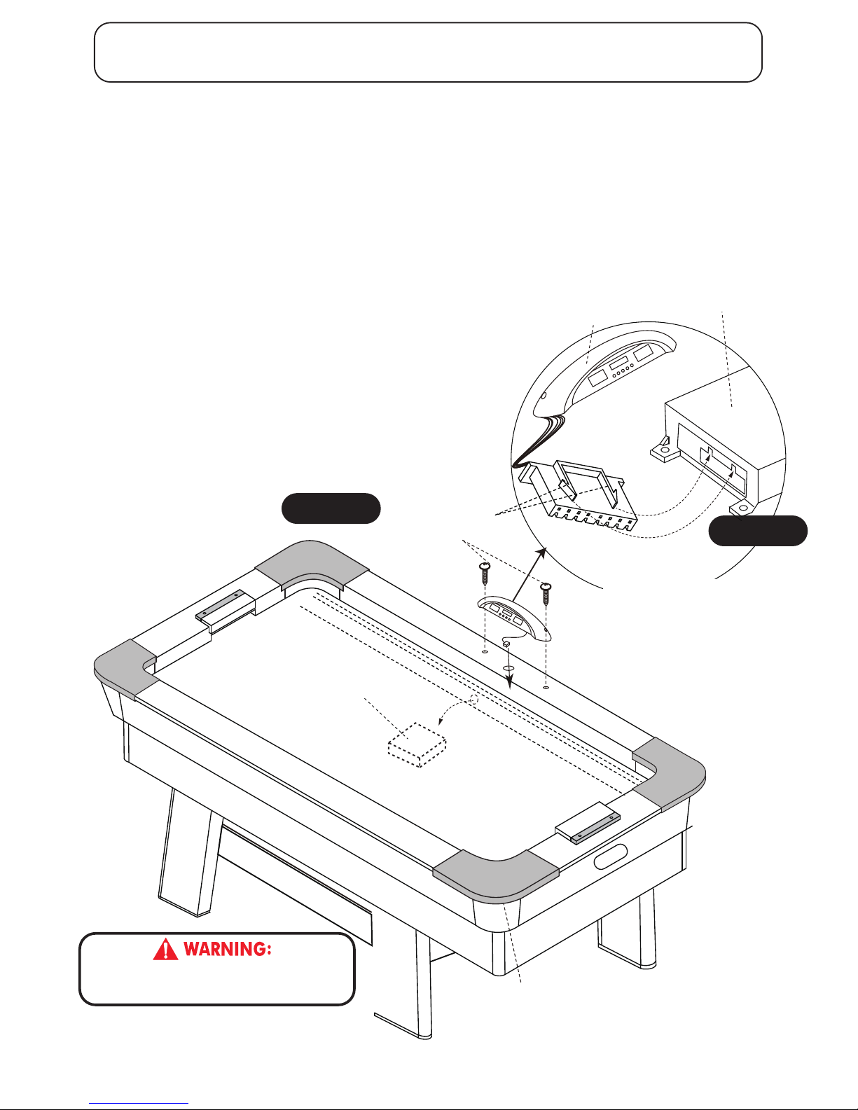
IMPORTANT NOTE:
WHEN TURING TABLE UPRIGHT
DO NOT REST TABLE ON THE SIDE OF
LEGS AS THIS COULD DAMAGE THEM.
STEP:5
With the help of at least four other adults, carefully lift and rotate table into upright position.
First,feed the Scorer Console (P12) plug down through the hole on one side of the long top
rail as shown in FIGURE 6.
Next, connect the Scorer Console plug to Junction Box (C3) as shown in DETAIL F.
Next, install Scorer Console (P12) onto long top rail using Philips Round Head Screws (H7)
as shown in FIGURE 6.
Tighten, but do not strip out Screws (H7).
PARTS REQUIRED:
H7 3.5 x 18mm Philips Round Head Screw 2 pcs - P12 Scorer Console1 pc -
H7
P12
Junction Box (
C3)
Junction Box (
C3)
tabs
FIGURE 6
DETAIL F
THIS STEP REQUIRES FOUR OR MORE ADULTS.
VERY CAREFULLY TURN THE TABLE OVER AND SET IT ON
ITS LEGS. BE CAREFUL. THE TABLE IS VERY HEAVY.
9
CONTROL
SENS
SENSOR1
NOTE:Make sure tabs on
plug are turned correctly
for correct installation.
NOTE:Corner caps are attached
only snug. This allows for the
unlikely but possible need to
repair the side track lights .
Page 10

CARE AND USE OF YOUR HOCKEY TABLE
.2
rofdednetnisitcudorpsihT ROODNI .ylnoesu
.5
DO NOT
DO NOT
DO NOT
It is suggested that this table be placed close to wall thus allowing the air motor
cord to NOT
be a trip hazard. Always turn air motor off when table is not in use.
.6
.elbatehtnonaelrobmilc,tis
.7
8.
This will damage the legs..tignivomnehwelbatehtgard
.elbatehtnosknirdtes
For long life and best play from your air hockey table, apply spray furniture polish
to a clean cloth and wipe down the playfield with air motor running to make the
st play and frequently thereafter.
3.
4.
DO NOT
operate the motor if the cord is damaged in any way.
Congratulations! You have now assembled your Hockey Table. Please note the Care and Use
instructions below to ensure many years of trouble free use of your Hockey Table.
.1
Use only a suitable 120v AC household outlet, and insure the cord is not a trip hazard.
HOCKEY GAME RULES:
1. This game is designed to be played with two (2) players, one at each end, or with four (4) players,
two at each end of the game table.
2. Flip a coin to determine who will begin play, or a face-off can be held at the center of the table.
3. Play begins when the puck is placed on the playing surface. Players must hit the puck with the
strikers and attempt to shoot into the opponent’s goal.
4. One point is awarded when a puck is shot into the opponent’s goal.
5. Winning the game: the winning score is accomplished by being the first player to reach a
predetermined score or by being the player to score the most points within a given period of time.
ELECTRONIC SCORER OPERATION:
POWER ON/OFF = Press POWER ON/OFF button to start or turn off the scoring unit.
START/PAUSE = Press START/PAUSE button to START the game. Press START/PAUSE button
during game will PAUSE or RESUME the game.
= Press SELECT/RESET button to select time options 5, 10, 15 minutes or No Time
Limit. Long press SELECT/RESET button to reset back to the game option.
LIGHT ON/OFF
SELECT/RESET
= Press LIGHT ON/OFF button to turn on or turn off the Light.
SOUND ON/OFF = Press Sound ON/OFF button to turn on or turn off the Sound.
10
NOTE: Use A8 and A9 Shim packs alone with a carpenter’s level to level table.
Page 11
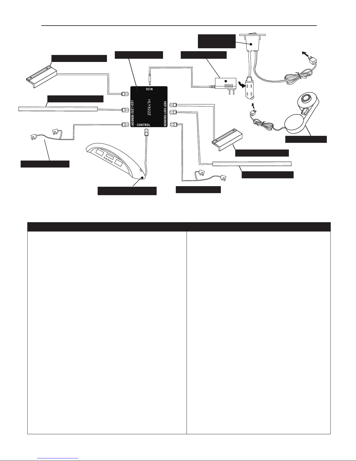
ELECTRICAL CONNECTIONS & SPARE PARTS DRAWINGS
To Wall
Outlet
C1 - ON/OFF
Switch
-
C2-A/C Adapter
C3 - Junction Box
C10 Right Sensor
C4 Right LED Lights
C10 Left Sensor
P12 -Scorer Console
PRODUCT PARTS LIST
G04865HLH1
8 x 35 mm Allen Head Bolt
G04865HLH2
8.5 x 22 mm Flat Washer
G04865HLH3
8 x 28 mm Phillips Round Head Screw
G04865HLH4
4 x 45 mm Phillips Flat Head Screw
G04865HLH5
3.5 x 12 mm Phillips Round Head Screw
G04865HLH6
3.5 x 14 mm Phillips Flat Head Screw
G04865HLH7
3.5 x 18 mm Phillips Round Head Screw
G04865HLH8 3.5 x 33 mm
Phillips Round Head Screw
G04865HLT1 M5 Allen Wrench
G04865HLA1
BLUE LED Striker
G04865HLA2
RED LED Striker
G04865HLA3
Felt Pad
G04865HLA4
Blue LED Puck
G04865HLA5
Red LED Puck
G04865HLA6
Red Puck
G04865HLA7
USB Cable
G04865HLA9
2 mm Shim Pack
G04865HLA8
1 mm Shim Pack
G04865HLP1 Air Hockey Table Cabinet (no motor) 1
G04865HLP2 Left Leg 2
G04865HLP3 Right Leg 2
G04865HLP4 End Apron 2
G04865HLP5 Side Apron 1
G04865HLP6 Side Apron with ON/OFF Slot 1
G04865HLP7 End Leg Panel
Side Leg Panel
Side Leg Support Board A
Side Leg Support Board B
A/C Adapter
Junction Box
2
G04865HLP8 2
G04865HLP9 1
G04865HLP10 1
G04865HLP11 Corner Post 4
G04865HLP12 Scorer Console 1
G04865HLC1 ON/OFF Switch 1
G04865HLC2 1
G04865HLC3 1
10
2
G04865HLC4 Lighting LED Rail
4
G04865HLC5 Corner Cap
G04865HLC6 Side Top Rail
4G04865HLC7 8 x 25 mm Allen Head Bolt
30G04865HLC8
3 x 9 mm Philips Round Head Screw
4G04865HLC9 8.5 x 22 mm Flat Washer
2G04865HLC10
Lower Puck Catcher with Sensor Wires
2G04865HLC11 Red LED Goal
2G04865HLC12 Blue LED Goal
1G04865HLC13 Air Blower
28
32
4
16
8
2
2
4
1
1
2
1
1
1
1
3
3
1
G04865HLK1 Hardware Kit
1
G04865HLM1 Owner’s Manual
1
Part#
Description Qty Part# Description Qty
MODEL: G04865
C11 Red LED Goal
C4 Left LED Lights
C12 Blue LED Goal
C13 Air Blower
11
Page 12
C5
C5
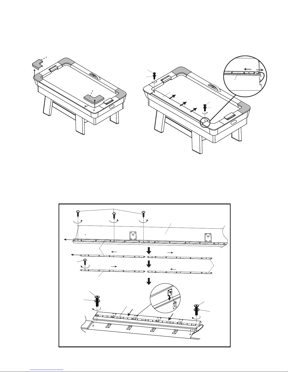
STEP ONE :
Remove Corner Caps (C5) from the table top rail.
STEP TWO :
Unscrew Bolts (C7) and slide Side Top Rail (C6)
from Air Hockey Table Cabinet (P1). And then
unplug the Lighting LED Rail (C4).
STEP THREE :
Unscrew Screws (C8), and separate Lighting LED Rail (C4) from each other.
Align the male and female connectors of the well Lighting LED Rail (C4), and Install them back
to Side Top Rail (C6) using Screws (C8) as shown in the diagram.
Next, connect the plug of Lighting LED Rail (C4).
Slide back and screw Side Top Rail (C6) to the table top rail using Bolts (C7) and washers (C9).
Lastly, press Corner Caps (C5) back to the table top rail.
Tighten, but do not strip out screws (C8).
Replacement of LED Light Rail
C4
C7
C7
C9
C9
C6
C8
C6
C4
C4
C6
C4
C8
C9
C7
C9
12
Page 13
13
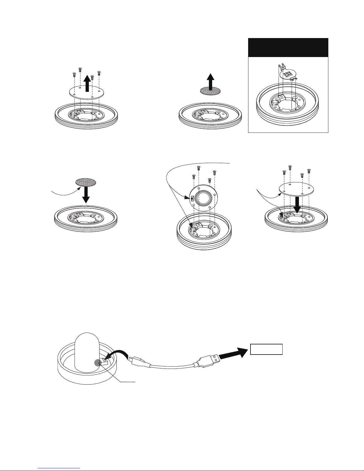
LED PUCK BATTERY CHANGE INSTRUCTION
STEP ONE:
Remove screws and back
cap from LED Puck using Small
Phillips Screwdriver (not provided).
STEP TWO:
Remove CR2016 Lithium
Battery 3V from LED Puck.
STEP THREE:
Insert new CR2016 Lithium Battery 3V
into LED Puck.
STEP FOUR:
Install back cap and secure screws with Phillps Screwdriver
(not provided).
Positive “+”
on bottom
side
LED STRIKER BATTERY CHARGE INSTRUCTION
NOTE:
Make sure the on/off
switch on the back
cap properly aligns
and fits into its slot in
the LED puck during
reassembly
IF BATTERY HOLDER BRACKET
MOVES, RE-INSTALL IT TO LED
PUCK AS SHOWN IN DIAGRAM.
USB Port
LED INDICATOR WILL LIGHT-UP DURING CHARGING AND
WILL TURN OFF WHEN ITS FULLY CHARGED.
Helpful Hint:
The LED puck battery will last approximately 7 hours of continuous play. The puck battery is not
rechargeable. Be sure to turn the switch to the “OFF” position when not in use to conserve your
battery life.
Helpful Hint:
The LED strikers each will require about 4 hours to fully charge up and will last approximately
7 hours of continuous play time. Be sure to turn the switch to the “OFF” position when not in use.
Page 14

y ESCALADE n a f o e s a h c r u p e h t n o , r e n w o l a n i g i r o e h t o t s d n e t x e y t n a r r a w r e m o t s u c s i h T
. ) " t c u d o r P " e h t s a d e r r e f e r r e t f a n i e r e h ( t c u d o r P S T R O P S
: N O I T A R U D Y T N A R R A W 0 9 f o d o i r e p a r o f , r e n w o l a n i g i r o e h t o t d e t n a r r a w s i t c u d o r P s i h T
. e s a h c r u p l a n i g i r o e h t m o r f s y a d
: E G A R E V O C Y T N A R R A W t c u d o r p s i h t , r e n w o l a n i g i r o e h t o t s t n a r r a w S T R O P S E D A L A C S E
e s o p r u p d e d n e t n i e h t r o f d e s u n e h w p i h s n a m k r o w d n a l a i r e t a m n i s t c e f e d m o r f e e r f e b o t
N E E B S A H T C U D O R P E H T F I D I O V S I Y T N A R R A W S I H T . s n o i t i d
n o c d n a e s u l a m r o n r e d n u
, E C I V R E S R E P O R P M I , E C N E G I L G E N , E S U E L B A N O S A E R N U , T N E D I C C A Y B D E G A M A D
R E H T O R O T C U D O R P E H T H T I W D E D I V O R P S N O I T C U R T S N I W O L L O F O T E R U L I A F
. P I H S N A M K R O W D N A L A I R E T A M N I S T C E F E D F O T U O G N I S I R A T O N S E S U A C
: T N E M E C A L P E R Y T N A R R A W , d o i r e p y t n a r r a w y a d 0 9 e v o b a e h t g n i r u D
e l b a r a p m o c a h t i w e c a l p e r r o s t n e n o p m o c t n e m e c a l p e r e d i v o r p l l a h s S T R O P S E D A L A C S E
e s a e l p , e r a c r e p o r p d n a e s u l a m r o n r e d n u e v i t c e f e d s i t c u d o r p f I . g n i s o o h c r u o t a t c u d o r p
. t p e D e c i v r
e S r e m o t s u C r u o t c a t n o c
. t p e D e c i v r e S r e m o t s u C / 888-996-2729 - 1
: t a s u e t i r W r O
6 0 7 7 4 N I , e l l i v s n a v E , 9 8 8 x o B . O . P - . c n I , s t r o p S ® e d a l a c s E
. t p e D e c i v r e S r e m o t s u C : n t t A
: t a s u l i a m - E r O
m o c . s t r o p s e d a l a c s e @ gameroom
Other than shipping requirements, no charge will be made for such replacement of in-warranty
products.
: S R E M I A L C S I D Y T N A R R A W T U O G N I S I R A S E I T N A R R A W D E I L P M I Y N A
S E I T N A R R A W D E I L P M I E H T O T D E T I M I L T O N T U B G N I D U L C N I , E L A S S I H T F O
E R A , E S O P R U P R A L U C I T R A P A R O F S S E N T I F D N A Y T I L I B A T N A H C R E M F O
T R O P S E D A L A C S E . D O I R E P Y A D 0 9 E V O B A E H T O T N O I T A R U D N I D E T I M I L S
R E H T O R O T C U D O R P E H T F O E S U F
O S S O L R O F E L B A I L E B T O N L L A H S
S E G A M A D R O S E S N E P X E , S T S O C L A T N E D I C N I R O L A I T N E U Q E S N O C
. E S U R E H T O Y N A F O R E M U S N O C E H T Y B D E R R U C N I
r o l a i t n e u q e s n o c r o s e i t n a r r a w d e i l p m i f o n o i t a t i m i l r o n o i s u l c x e e h t w o l l a t o n o d s e t a t s e m o S
. u o y o t y l p p a t o n y a m s n o i s u l c x e r o s n o i t a t i m i l e v o b a e h t o s , s e g a m a d l a t n e d i c n i
: S E I D E M E R L A G E L e v a h o s l a y a m u o y d n a s t h g i r l a g e l c i f i c e p s u o y s e v i g y t n a r r a w s i h T
. e t a t s o t e t a t s m o r f y r a v y a m h c i h w s t h g i r r e h t o
Y T N A R R A W D E T I M I L Y A D 0 9
14
 Loading...