

Page 1
Instruction and Assembly Manual
Version 1.2 (31 Mar 2017)
Page 2
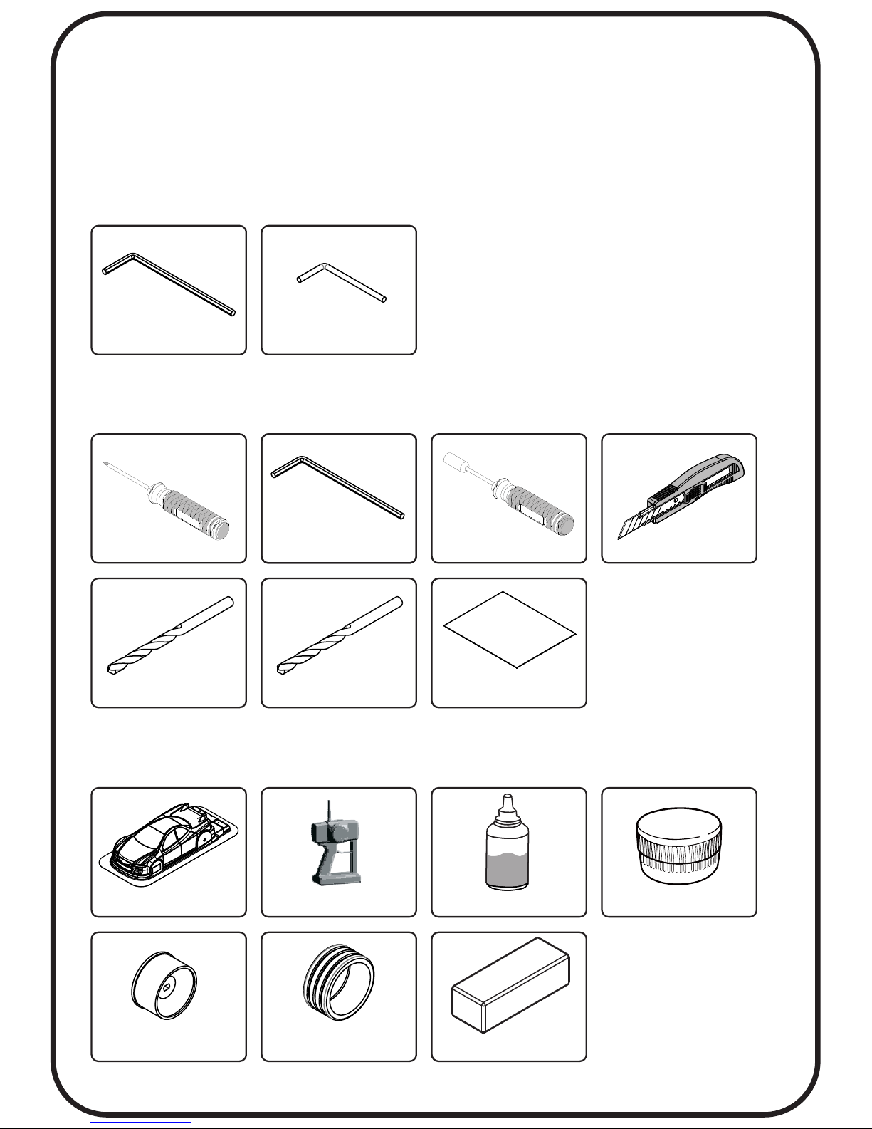
Tools Needed (Not Included) :
Equipment required :
Tools Included :
Thank you for purchasing this Atomic product. BZ 2017 is a high
performance competition machine for 1:28 scale. Please read this
manual in detail in order to have proper assembly of this product
and wish you have fun with it.
Car Body Radio System Ball Diff Oil Grease
Rim Tire Battey
Small Screw Driver 1.5mm Allen wrench
1.3mm Allen wrench Diff tool
Hex Nut Driver
4.5mm
Hobby Knife
1. 5mm Drill Bit 2.0mm Drill Bit
#1500 Sandpaper
Page 3
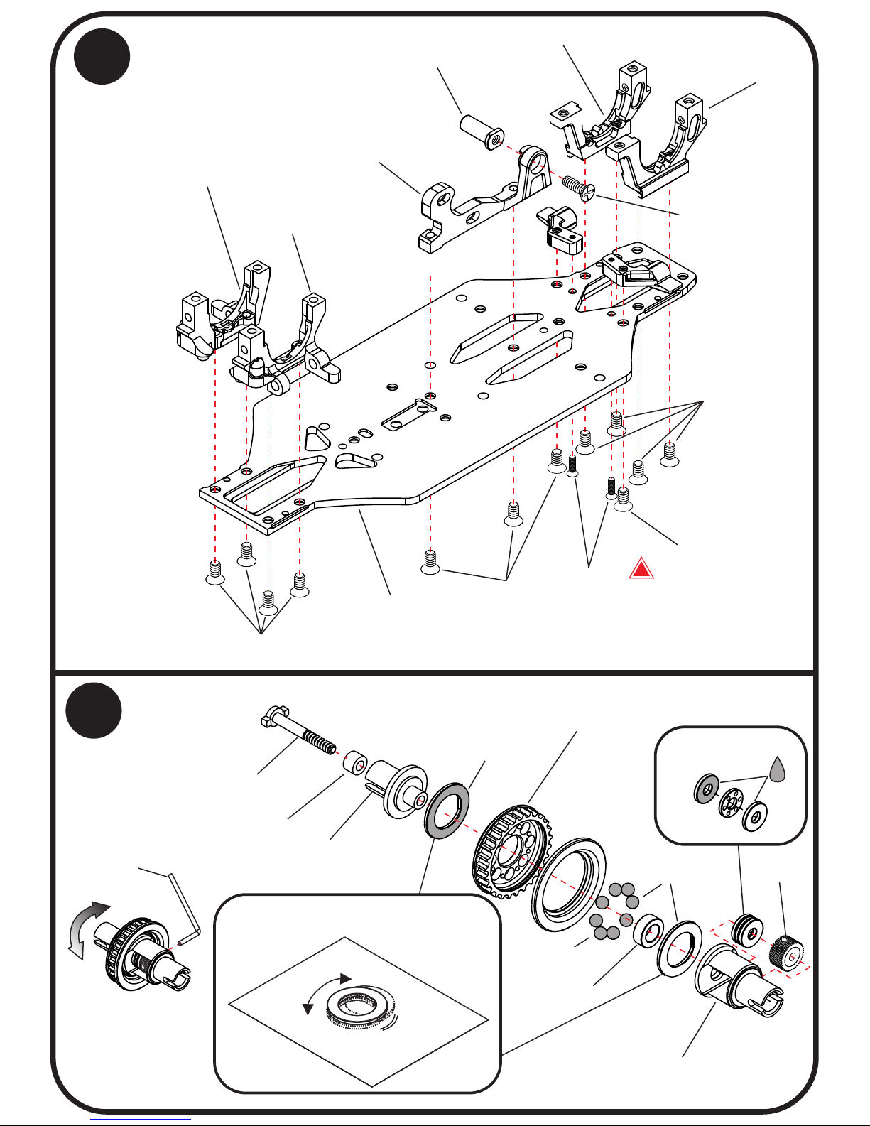
1
2
Apply Thrust
Bearing Grease
oil
Polish the diff plate and thr ust
bearing plate with #1500 sand
paper
2.38mm
Thrust Ball
Diff Housing (Short)
Diff Housing (Long)
27T Pulley
Diff rubber
Diff Scwer
Pulley Collar
Diff Nut
Ball differential
Attaching bulkheads
P.1
Apply Grease
Apply Ball Diff
Grease
Loosen
Tighten
After assembly
Diff tool
Bulkhead B (+0)
Bulkhead A (+0)
Motor Mount
Spur gear shaft
2x6KM
(Flat Head)
2x4KM
Lower deck
M2x4KM
2x4KM
2x4KM
1.2x4KA
(Flat head self taping scr ew)
Bulkhead rear L
Bulkhead rear R
!
Page 4
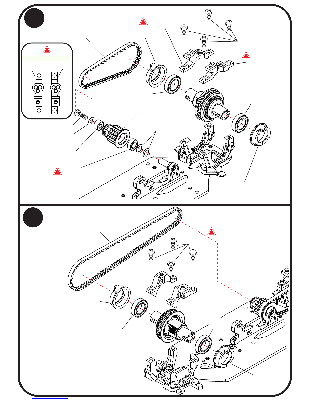
M2x4PM
Bearing hub
Bearing hub
6x10x3
Bearing
6x10x3
Bearing
2x6PM
2x4 shims
(around 0.2mm)
2x5x2.5
Bearing
3x6x2
Bearing
16T Cnter Pulley
Drive belt (Short)
M1.9x4PA
(Silver Color, Self Taping screw)
Bearing hub
Drive belt (Long)
3
Attaching Rear Ball differential
& Center Pully
4
Attaching Front Ball differential
3x5 shims
(around 0.5mm)
Upper Rear
Bulkhead L
Upper Rear
Bulkhead R
6x10x3
Bearing
Bearing hub
6x10x3
Bearing
P.2
!
!
!
Upper Rear Bulkhead
L
R
!
!
Page 5
5
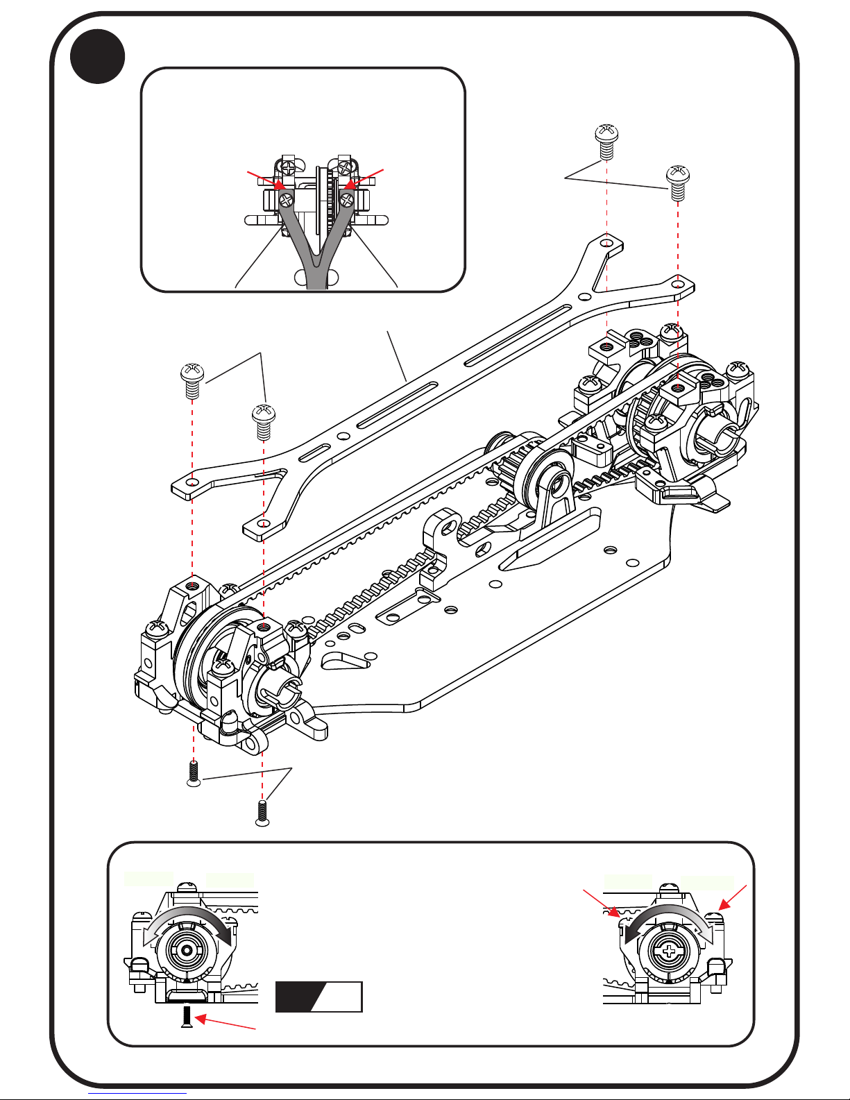
Attaching Upper deck
Make sure the carbon top deck can be
easily put on the bulk head. otherwise, use
sand paper to trim the end of top deck.
P.3
1.2x 4KM (Flat Head, Mac hine Thread)
For Adj usting Bearing Hu b
2x4P M
Uppe r deck
2x4P M
Loosen
Tighten
Rear
Adjust the bearing hub position to
adjust belt tension.
Middle position is recommended.
Loos en the screw For Adjus ting Bearing Hub
Loosen
Tighten
Front
L R
Page 6
P.4
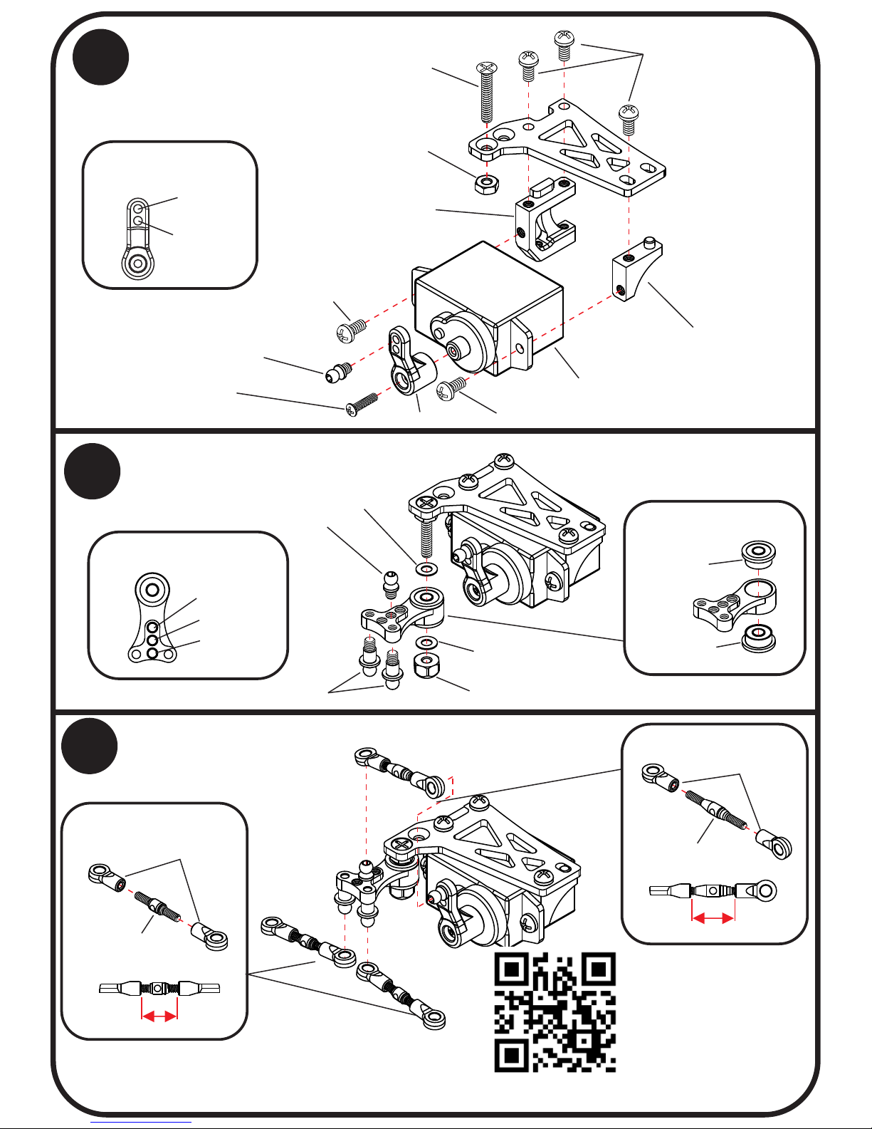
Attaching Servo Mount
6
Quick
Smooth
Steering Respond
Attaching Steering System
7
8
Attaching Steering linkage
Quick
Smooth
Neutral
Steering Respond
2x4PM
1.5x6PB
Servo
not included
Servo Mount A
Servo Mount B
Steering System
Linkage Ball A
Servo horn
2x12KM
M2 Metal nut
2x4PM
2x4PM
Linkage Ball A
2x4x0.2
shims
2x4x0.2
shims
Linkage Ball B
M2 Lock nut ( )plastic
7.1mm
8.3mm
Linkage assembly
2.5mm Ball end
1.5X12mm
Turnbuckles
2.5mm Ball end
1.5X14mm
Turnbuckles
Linkage assembly
2x5x2.5
Bearing
2x5x2.5
Bearing
Video to show how to
smooth ball links please
scan the QR code
ht t p s :/ /y o u t u. be / R M hk oI U S _ o g
Page 7
9
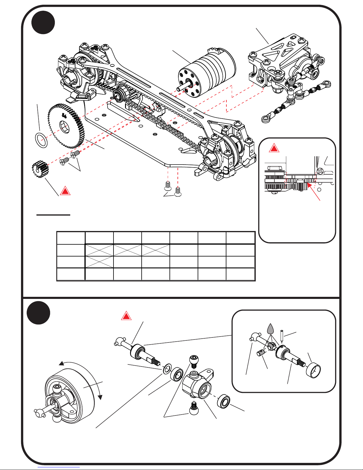
Attaching Spur gear & Motor gear
2x4KM
Motor
Motor pinion
Spur gear
5x7x1mm
O-ring
Servo assembly
P.5
!
2x4KM
!
Attention:
Motor
Carefully adjust the
position of pinion,
make sure it doesnot
touch the front belt.
14 15 16 17 18
54 5.70 5.36 5.06
56 6.75 6.30 5.91 5.56 5.25
58 7.53 6.99 6.53 6.12 5.76 5.44
Motor Pinion
Spur Gear
( is recommended for 5500KV motor )5.56
( )
Spur gear
x
1.69
Motor gear
= Gear ratio
Axles assembly
3x5 shims
About 0.2~0.3mm
3x6x2
Bearing
3x6x2
Bearing
Steering block
Linkage Ball 4mm
(AMZ011)
Wheel axle
Swing shaft
Cross joint
Lock collar
oil
CVD assembly
1x5.5mm
After assembly
Make sure the wheel
rotate freely.
Insert shims to
adjust the play
of CVD
Not included
Build 2 Sets
10
Long CVD
!
Page 8
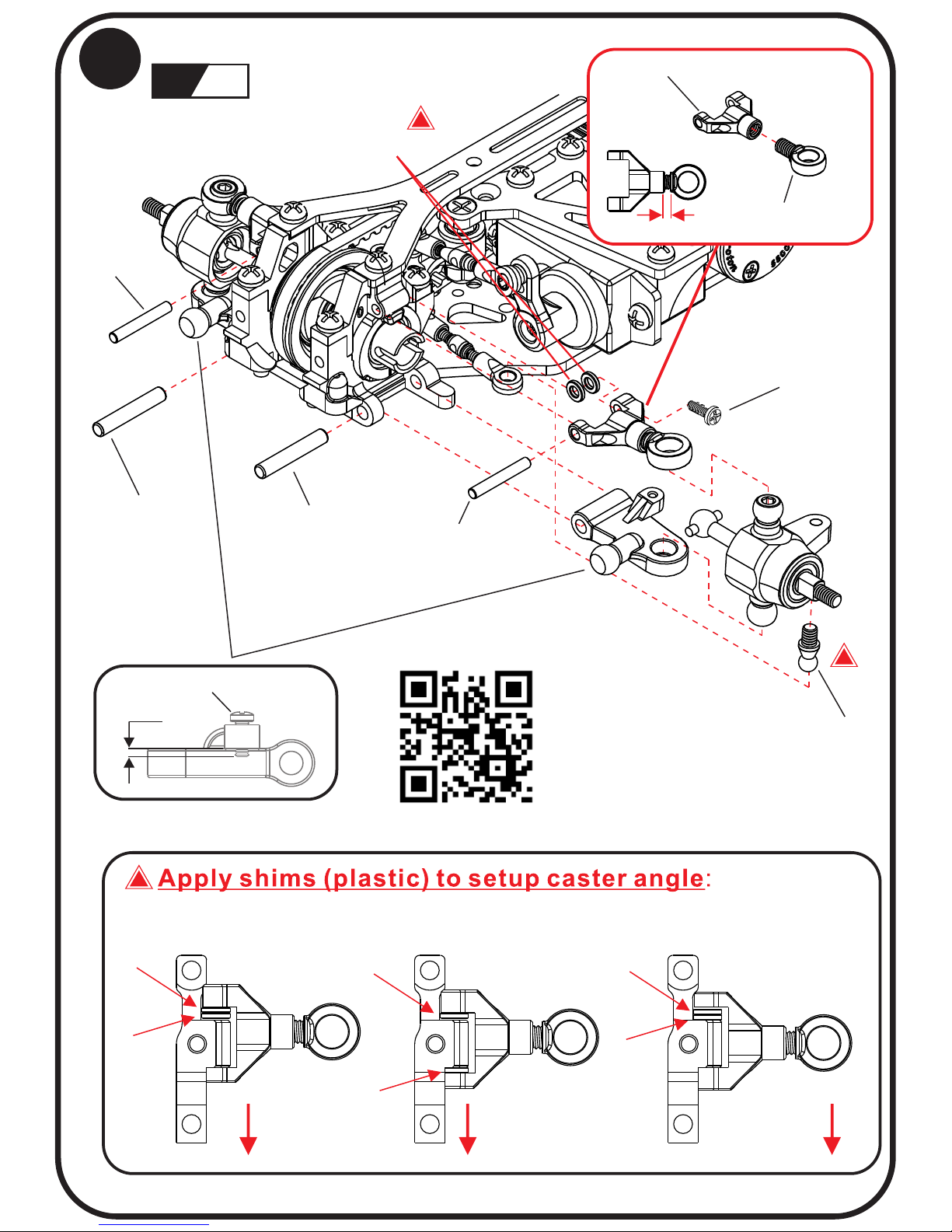
Attaching Front arms
11
!
L R
0.7mm
1.2x4 PB Droop screw
1.0mm
2x12mm
1.5x11mm
1.5x11mm
1.4X4KM
1.5x3x0.7
shims (plastic)
!
2x12mm
Camber Adjustable arm
Linkage Ball C
Linkage Ball end
4 degree
2 degree 0 degree
Attention to camber arm direction
Front
Front
!
P.6
Front
Video to show how to
smooth ball links please
scan the QR code
ht t p s :/ /y o u t u. be / R M hk oI U S _ o g
** using sand paper to make the shims thinner if the arm is not moving
freely.
Page 9
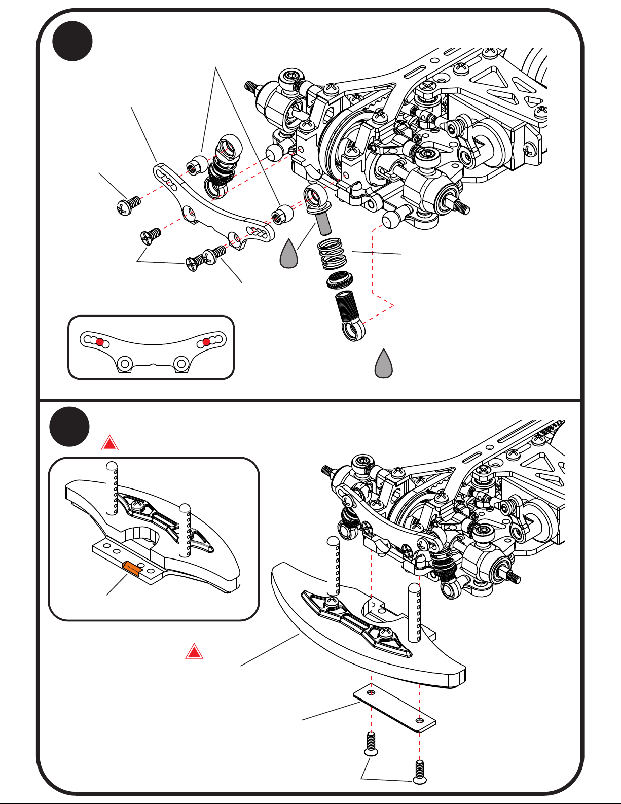
12
Attaching Front shocks tower
oil
Sping
oil
We recommend to apply #30000
Different Grease to the sho cks.
P.7
2x4KM
2x4PM
2x4PM
Default setup
2x6KM
Front body mount
( )Not included
Body mount cover
!
Not included
Trim this part to avoid the touch of
front belt
Caution:
!
13
Attaching Front Body Mount
Front Shocks tower
Shocks Linkage Ball 4mm
Page 10
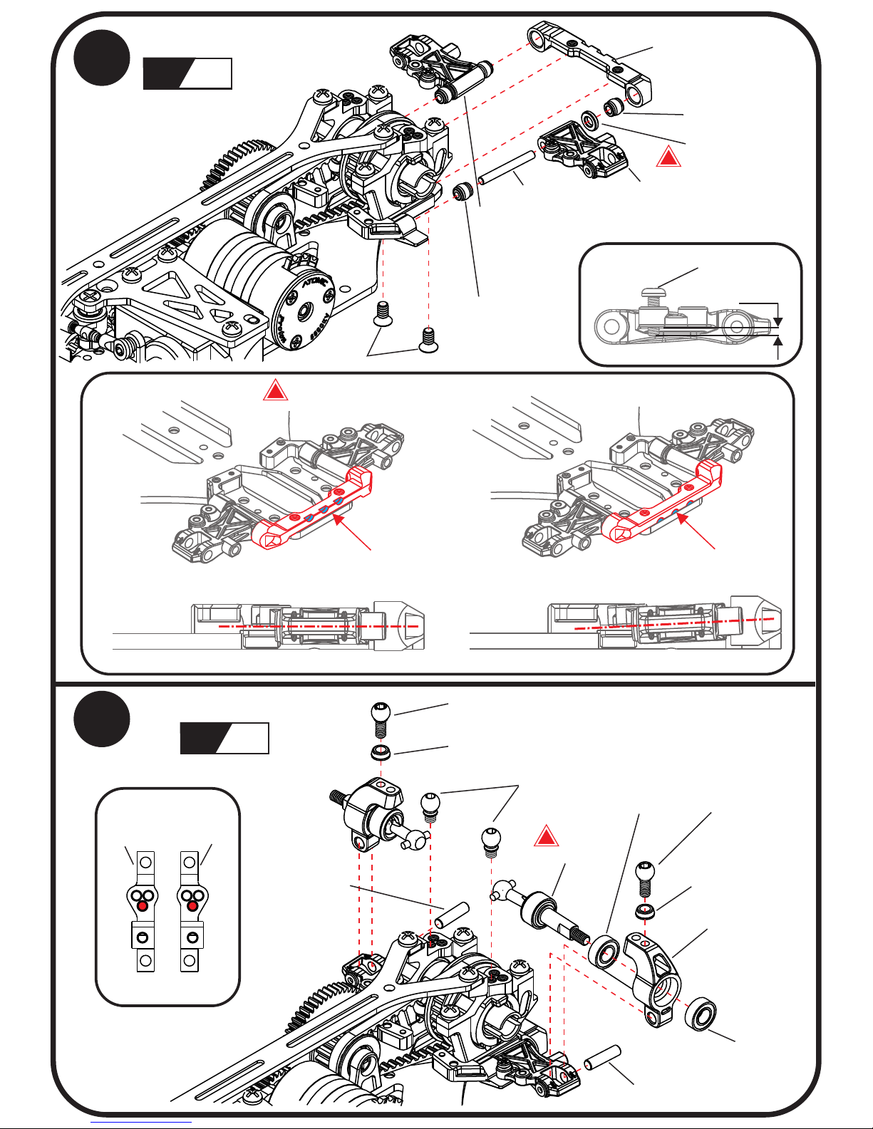
Upper Rear Bulkhead
L
R
Default setup
Short CVD
!
L R
L R
14
Attaching Rear arm
15
Attaching Rear Upright
!
Rear Suspension arm (L)
Rear Suspension arm (R)
Suspension ball
Suspension ball
1.5X13mm pin
2x4KM
Dots facing up:
Dots facing down:
More on-power grip
Rear Toe in mount installation direction
Default setup
!
2X7.5mm pin
2X7.5mm pin
3x6x2
Bearing
3x6x2
Bearing
Rear Upright
3.5mm long
Linkage Ball
3.5mm long
Linkage Ball
3.5mm short
Linkage Ball
Linkage Ball collar
Linkage Ball collar
0.7mm
1.2x4PB
P.8
1.5x2.5x0.35
shims (white)
Page 11
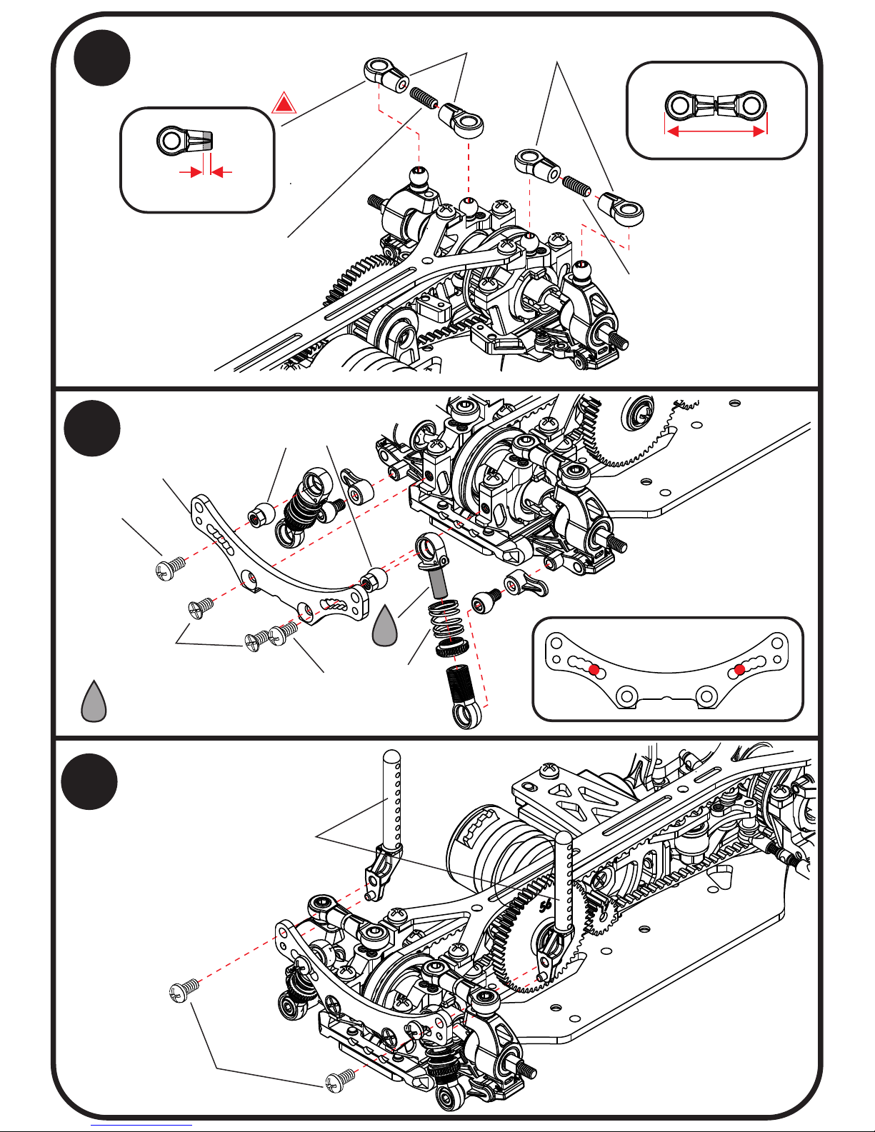
1.2mm
Cut
18.8mm
16
Attaching Rear camber linkage
3.5mm linkage ball
!
M2x6 set screw
M2x6 set screw
Default setup
P.9
17
Attaching Rear shocks tower
18
Attaching Rear body mount
oil
Sping
oil
We recommend to apply #30000
Different Grease to the sho cks.
2x4KM
2x4PM
2x4PM
Rear Shocks tower
Shocks Linkage Ball 4mm
Rear body mount
2x4PM
Page 12
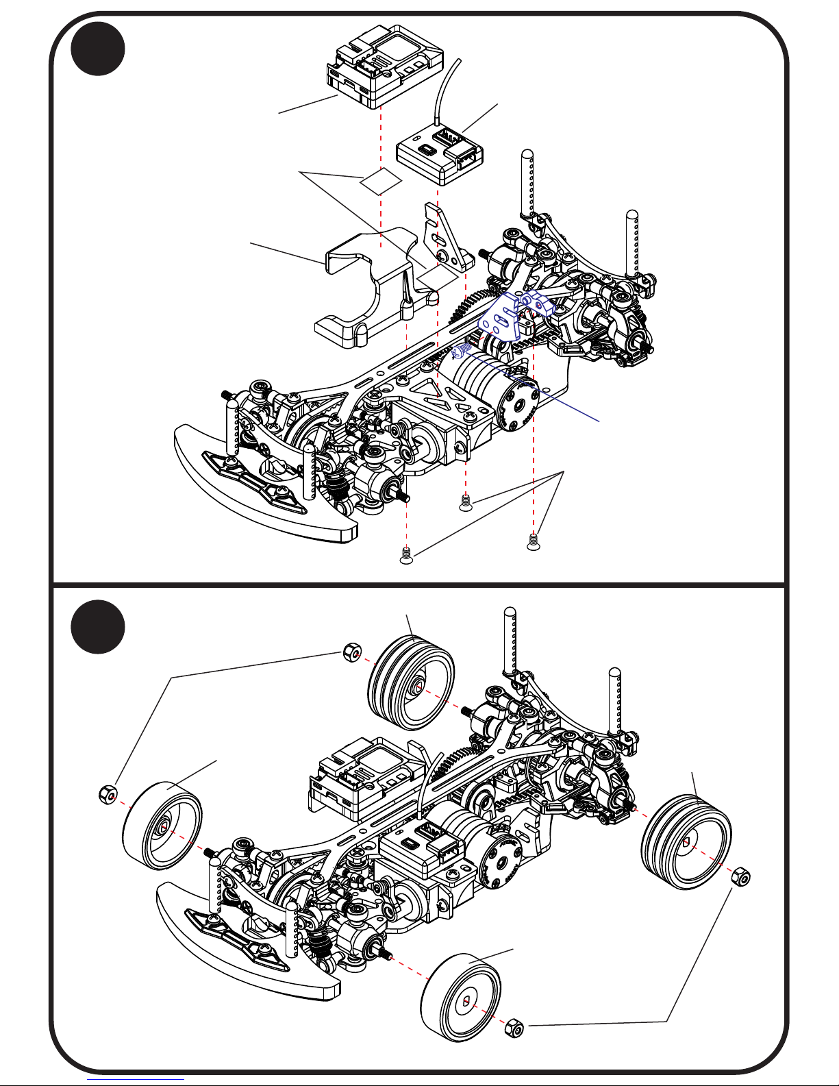
P.10
19
Attaching other parts
20
Attaching tire & wheel
Speed controller
RX
Double-sided Tapes
Battery mount
2x4KM
2x4PM
M2 Lock nut
( )plastic
M2 Lock nut
( )plastic
Not included
Not included
Not included
Not included
Page 13
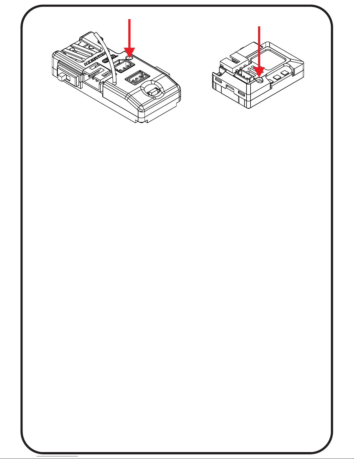
ESC/Radio Calibration:
1. Turn on the transmitter, set parameters on the throttle channel like
“D/R”, “EPA” and “ATL” to 100% (for transmitter without LCD, please
turn the knob to the maximum) and the throttle “TRIM” to 0 (for
transmitter without LCD, please turn the corresponding knob to the
neutral position). For Futaba radio transmitter, the direction of
throttle channel shall be set to “REV”, while other radio systems shall
be set to “NOR”. Please ensure the “ABS braking function” of your
transmitter must be DISABLED.
2. Start with transmitter on
3. ESC turned off but connected to a battery.
4. Holding the SET button and turn on the ESC, the RED LED on the
ESC starts to flash and then release the SET button immediately.(it
is now in setup mode)
3. Steps to Set the neutral point, the full throttle endpoint and the full
brake endpoint:
3.1 Leave the throttle trigger at the neutral position, press the SET
button, the RED LED dies out and the GREEN LED flashes 1 time.
3.2 Pull the throttle trigger to the full throttle position, press the SET
button, the GREEN LED blinks 2 times.
3.3 Push the throttle trigger to the full brake position, press the SET
button, the GREEN LED blinks 3 times.
3.4 The motor can be started 3 seconds after the ESC/Radio
calibration is complete.
P.11
Page 14
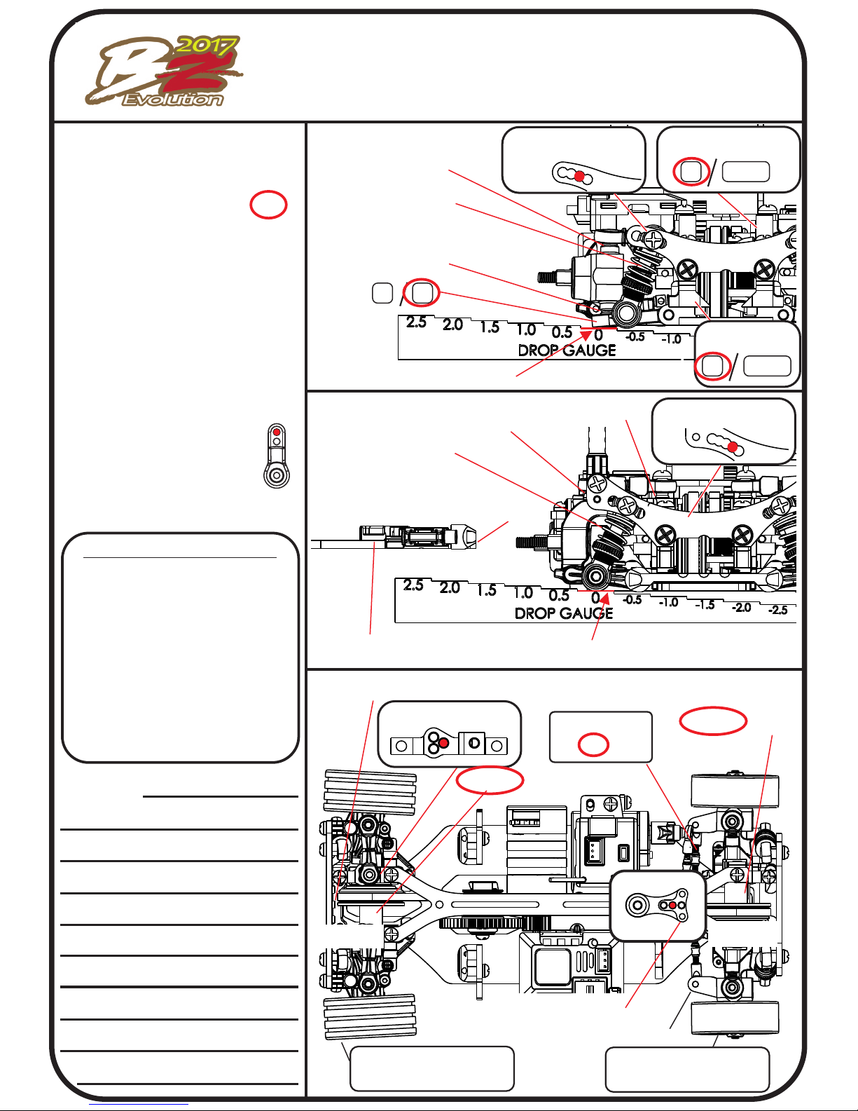
Default Setup sheet
Date:______ Place:_____ Track:_____
Driver:_____ Best lap:______ Final position:____
Body:___________
.
Wheel Base:
.
90 / 94 / 98
Motor:__________
.
Spur gear:_______
.
Pinion gear:______
.
Gear ratio:_______
.
Battary:_________
.
Servo:________
.
Weight:_______
Rear
Front
Heigth:____
Down stop:___
Shim:___mm
Shim:___mm
Spring:____
Grease:_____
Upper Bulkhaed
0
+2.5
Bulkhaed
0
+2.5
Arm:
N
W
Spring:____
Grease:_
Shim: ___mm
Wheel offset:___
Tire:_____
Wheel offset:___
Tire:_____
Ball Diff / _____
in / out ____
toe :
Speed controller
Program card setup
1.Running Mode(1~3) ___
2.Low Voltage Cut-Off(1~6)___
3.Over-heat protection(1~2)__
4.Neutral Range(1~3)___
5.Start Mode (punch)(1~9)___
6.Max. Forward Force(1~5)___
7.Max. Reverse Force(1~4)___
8.Max. Brake Force(1~5)___
9.Drag Brake Force (1~8)___
10.Initial Brake Force(1~4)___
11.Timing(1~8)___
Note:
Shock Tower:
Shock Tower:
Shim:___mm
Shim:___mm
Heigth:____
Down stop:___
Spacer:__
Spacer:__
Rear
Front
toe in mount:__Dot
installation hole:
Camber: F___ / R___
Ball Diff / _____
Caster :__
0
0
0
0
2.2
-1.2
#30000
Red
White
#30000
0
0
2.3
-0.5
AMZ-OP011-LTC-2
Atomic 5500KV
56T
17T
5.56
Atomic 360mAh
BZ-UP017
2
5
1
2
4
5
2
3
1
1
6
3
1.5
1.5
0.5
4 degree
N1.0
W2.5
Shim: ___mm
0
0
Page 15
www.rcatomic.com
End of Assembly
 Loading...