

Page 1

BZ3 Instruction manual
1
1
Page 2
BZ3 Instruction manual
2
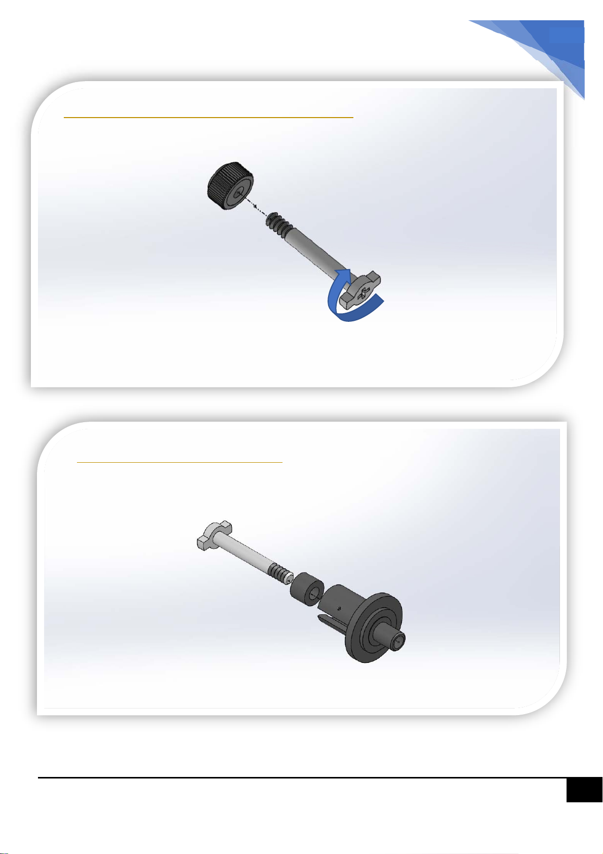
Step 1 – Prepare the Diff Lock Nut
Hold Diff Lock Nut by pliers
Before assembling the Ball Diff, make a
thread to the lock nut first, by using the
diff screw.
Diff Screw
Step 1.1– Diff Assembly
Diff Rubber Pressure Collar
Insert the diff screw and rubber pressure collar
into the diff cup
2
Page 3
BZ3 Instruction manual
3
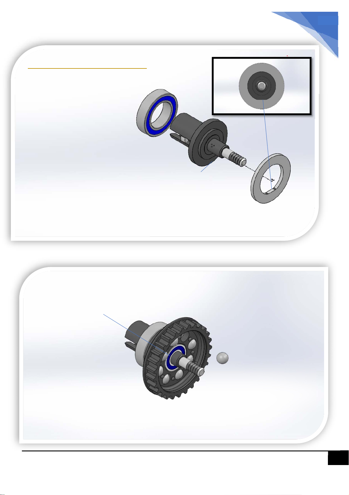
Attention: the “D” Shape
Step 1.2– Diff Assembly
Insert the Bearing (6*10*3) to the drive cup
Apply ball diff grease to the cup and attach the diff plate.
Diff grease is act as the adhesive to hold the cup and plate
together.
Insert the Bearing (3*6*2) to the pulley, and attach pulley to the
diff cup
2.381mm balls
Apply Ball Diff Grease the balls and
insert them to the diff pulley.
3
Page 4
BZ3 Instruction manual
4
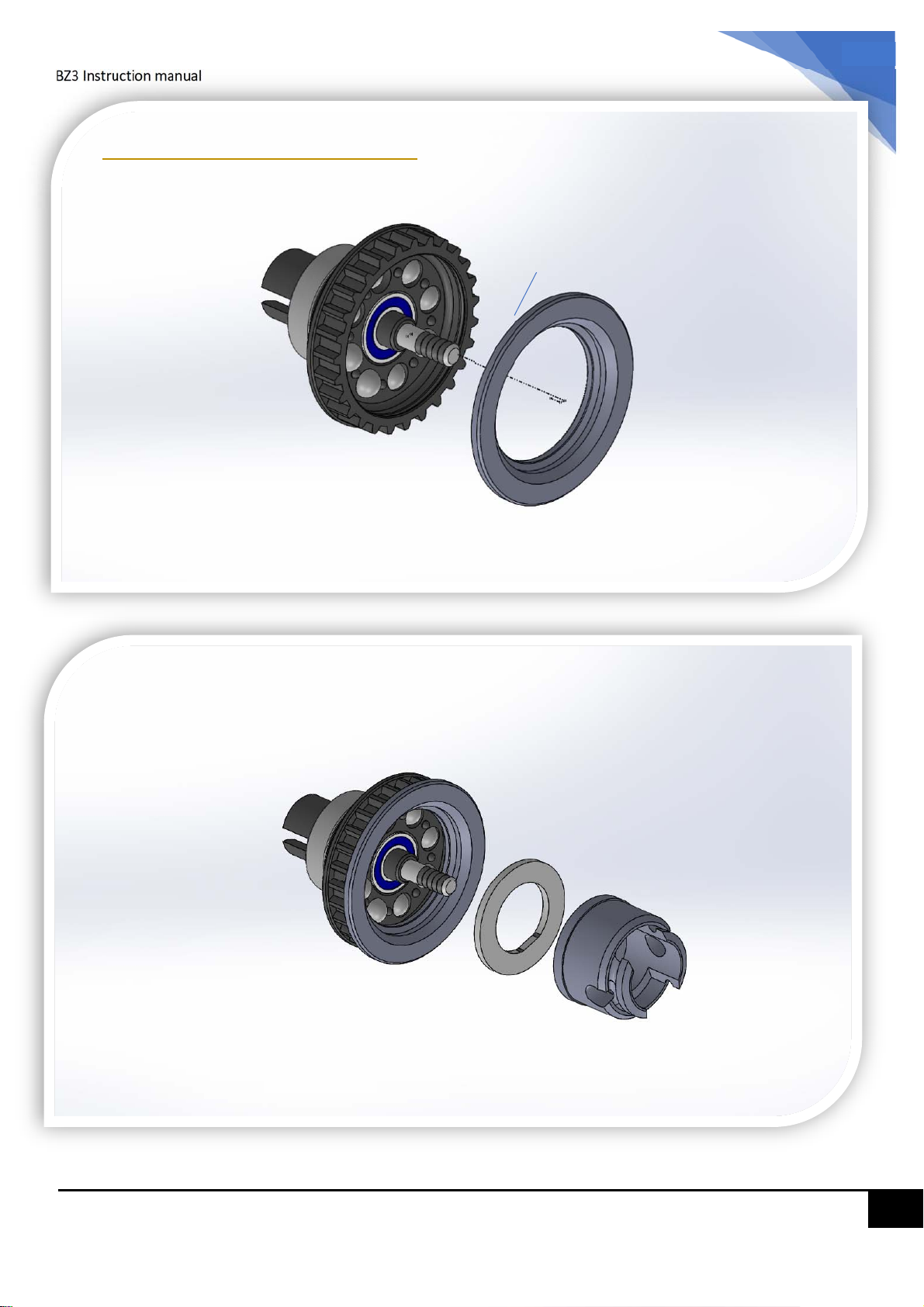
Step 1.3– Diff Assembly
Apply instant glue and fix the pulley ring.
Apply ball diff grease to the cup and attach the diff plate.
Diff grease is act as the adhesive to hold the cup and plate
together.
4
Page 5
BZ3 Instruction manual
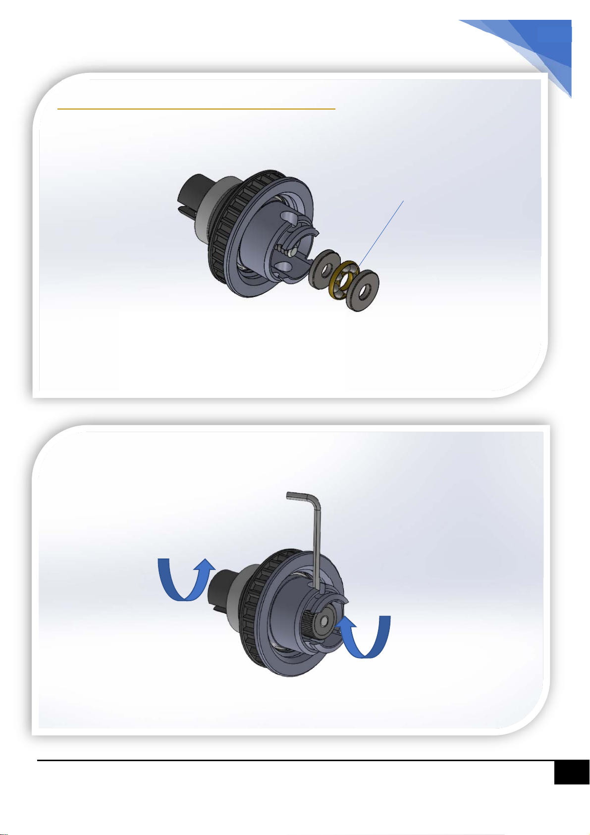
Step 1.4– Ball Diff Thrust Bearing
5
Attach the thrust bearing set to the cup
Apply thrust bearing grease to the ball-ring.
Use the diff tool to hold the diff lock nut,
And tighten the ball diff.
Diff lock nut
5
Page 6
BZ3 Instruction manual
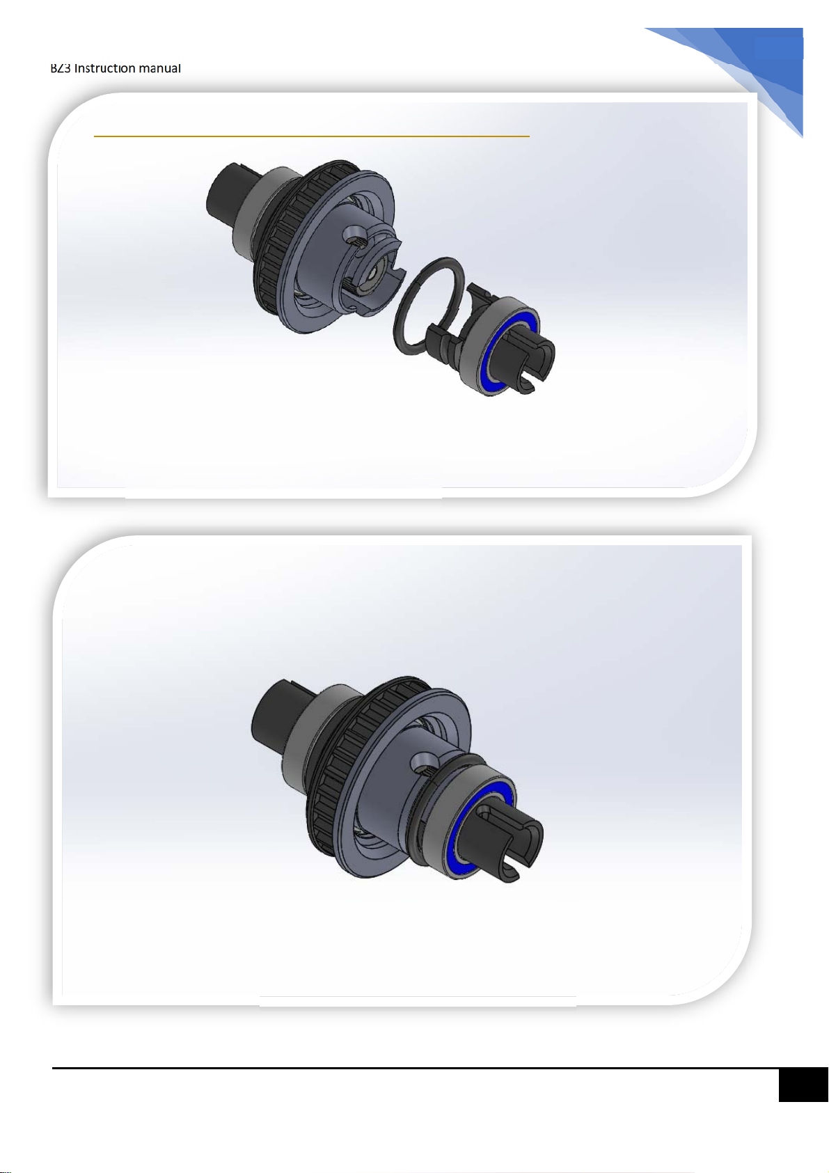
Step 1.4– Ball Diff Assemble Finished
6
Attach the out-drive cup to the ball diff
body, and use the O-ring to secure the cup.
Install the 6*10*3 bearing.
Now build the second diff, repeat above
steps.
6
Page 7
BZ3 Instruction manual
7
M2*10 KM
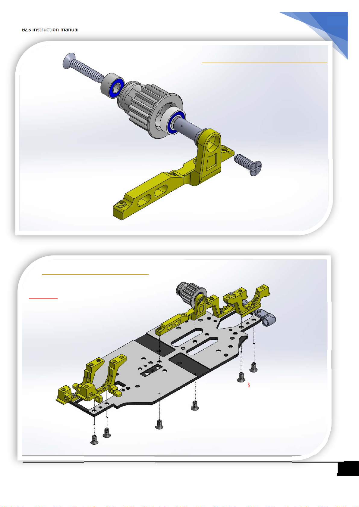
Step 2.0– Motor Mount
Drive pulley
2*5*2.5 bearing
3*6*2 bearing
3*6*2 bearing
M2*4 KM
Step 3.0 - Bulkheads
Caution:
For Front and Read Bulkheads, must use
M2*3 screw. CANNOT use M2*4mm.
M2*4
M2*3
M2*3
M2*4
M2*4
M2*3
M2*3
7
Page 8
BZ3 Instruction manual
8
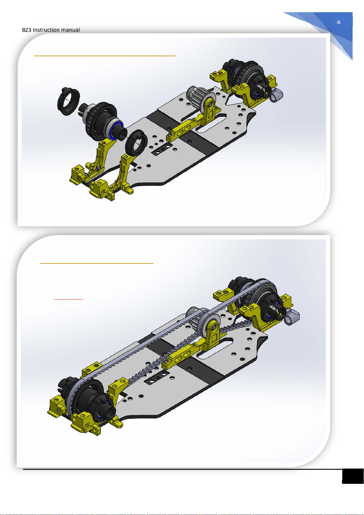
Step 4.0 – Belt and Ball Diff
Step 5.0 –Fixing Belts
Caution:
Pay attention to the orientation of ball diffs
and belts
8
Page 9
BZ3 Instruction manual
9
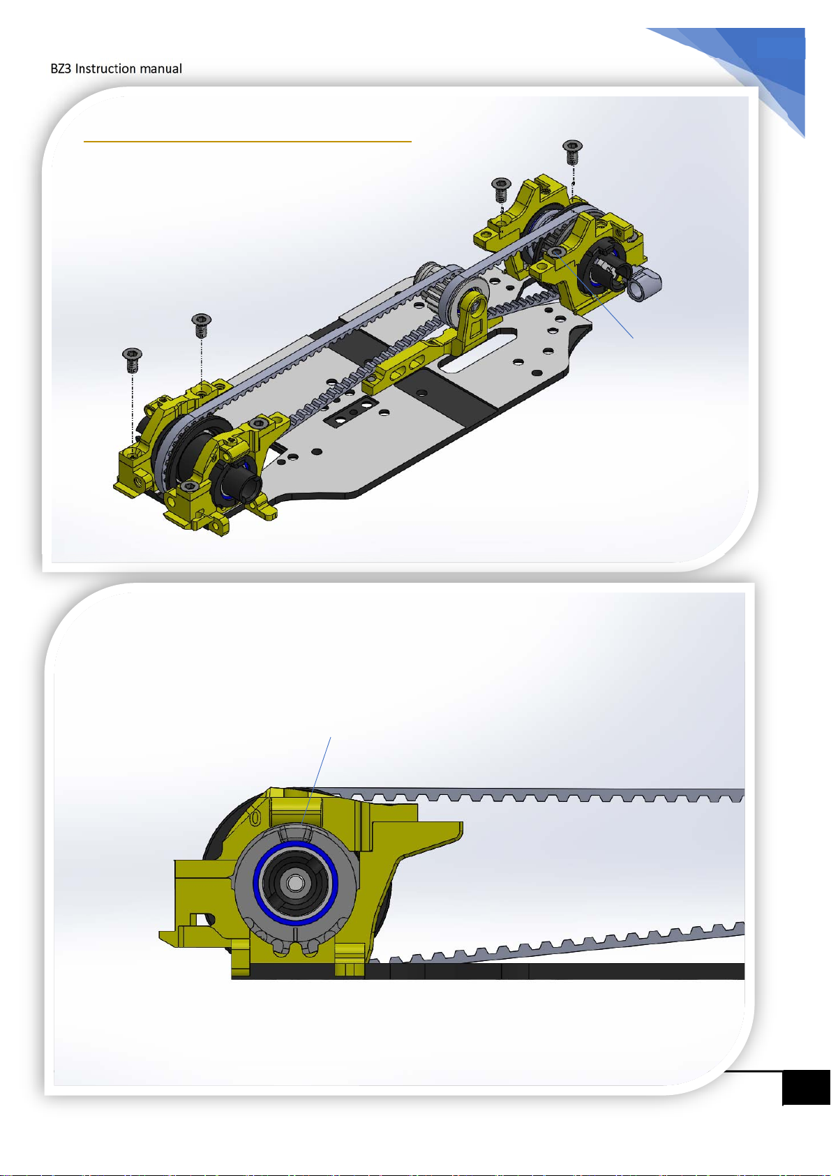
Step 6.0 – Upper Bulkheads
M2*4
M2*5
M2*4
M2*4
M2*4
M2*5
Adjust the bearing hub position to adjust belt tension.
Middle position is a good start.
9
Page 10
10
BZ3 Instruction manual
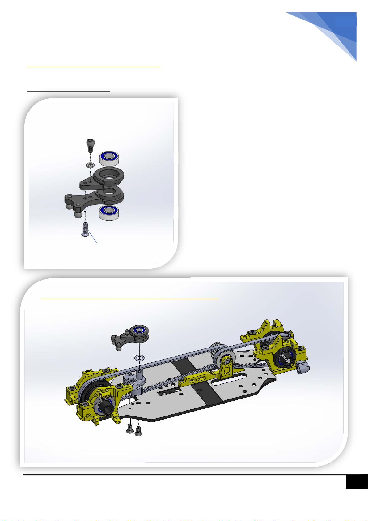
Step 7.0 – Steering Crank
SolidSteeringcrank(stock)
1.5*2.5*0.35
2.5 ball head
3*6*2
2.5 ball head
3*6*2
M1.4 *4 screw is used to go thru the
cranks.
Step 8.0 – Steering Crank Support
3*4*0.1 shim
M2*4
10
Page 11
BZ3 Instruction manual
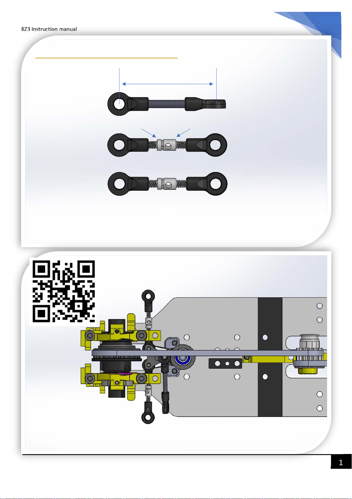
Step 9.0 – Steering Linkages
19mm Center to Center
11
2.5 Ball Cap
Normal Thread Side Reverse Thread Side
2.5 Ball Cap
Make 3 Linkages as above, approximately
19mm center to center long.
Fix the linkages as shown
Video to show how to smooth ball links, please scan the QR code.
11
Page 12
12
.
2
T
r
BZ3 Instruction manual
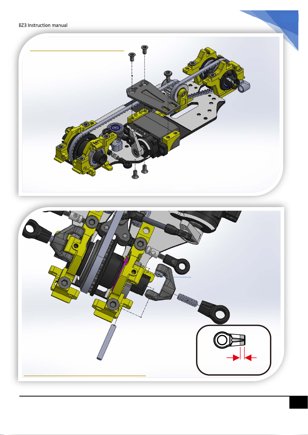
Step 10 - Servo Mount
M2*4
M2*4
M2*4
M2*4
M2*4
1.5*2.5*0.35 washer (2pcs)
2*6 rod
3.5 ball cap
1.5*11 pin
Step 11 – Front Upper Arms
1
im
mm
12
Page 13
BZ3 Instruction manual
13
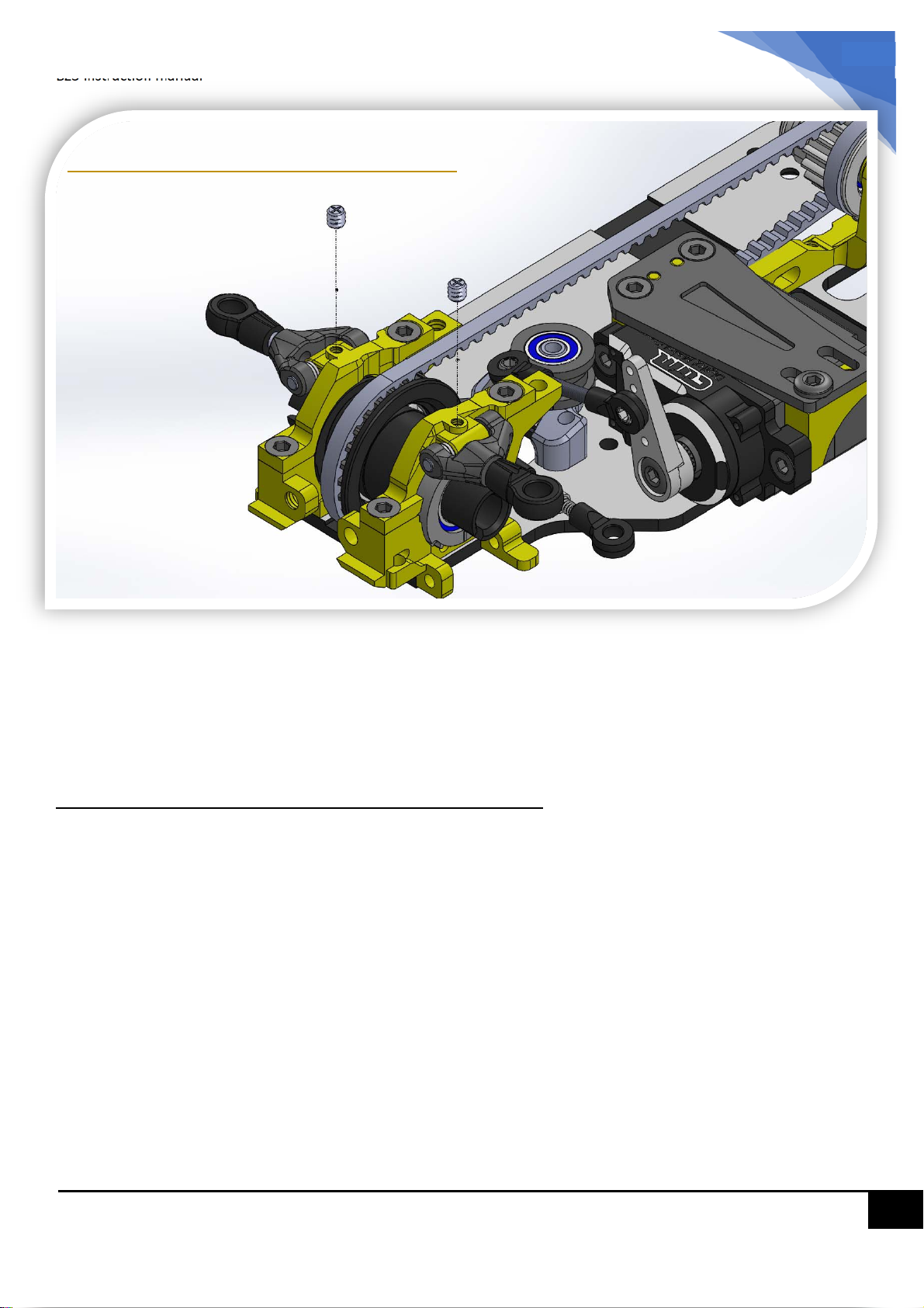
Step 11.1 – Front Upper Arms
M2*2.5 set screw
M2*2.5 set screw
Note:
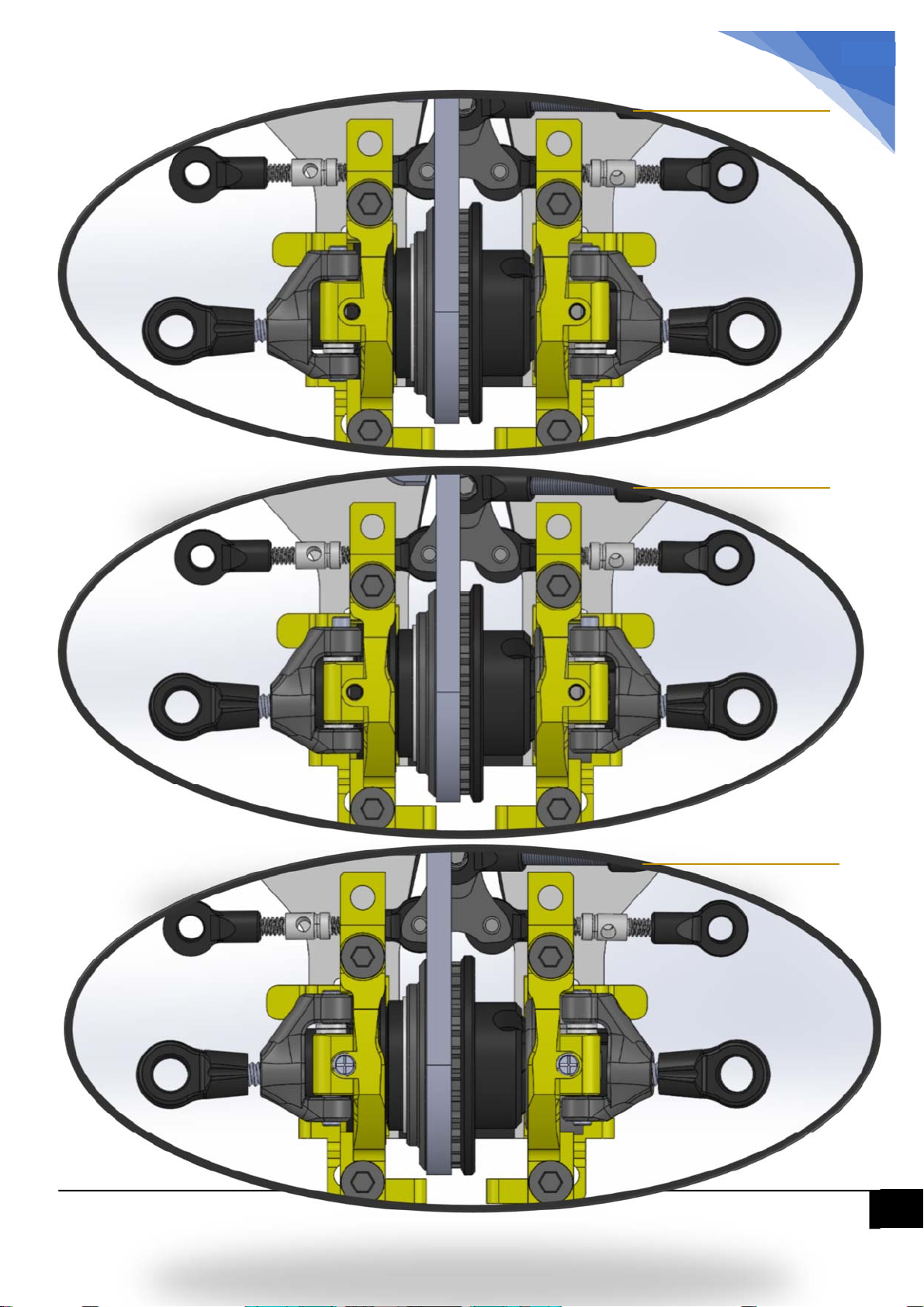
1.5*2.5*0.35 white washer is used to adjust the Front Caster Angle (upper arm inclination).
More caster angle will generate more steering but degrease in stability. We recommend you
try different degree to find the best position for you.
Every 0.35mm move = 1-degree change of caster angle.
13
Page 14
14
BZ3 Instruction manual
0 degree caster
1 degree caster
2 degree caster
14
Page 15
15
BZ3 Instruction manual
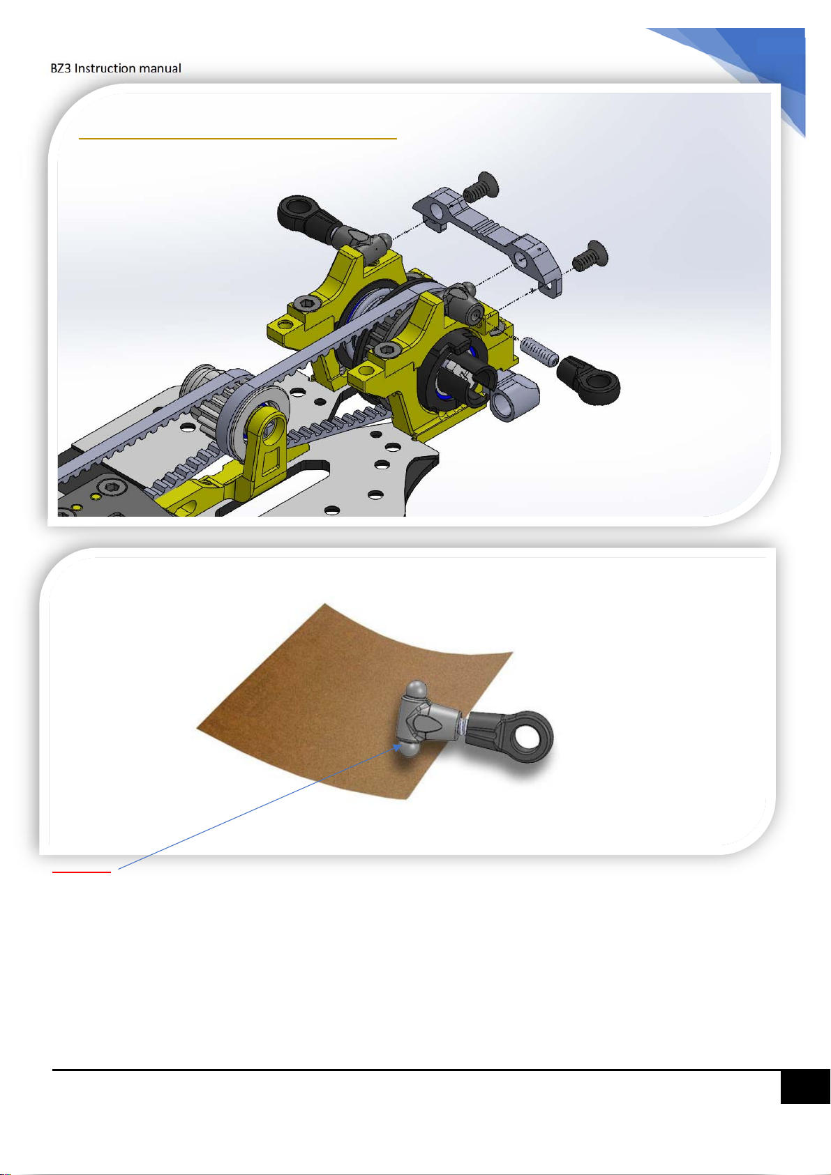
Step 12 – Rear Upper Arms
M2*3
M2*3
M2*6 Rod
3.5 Ball Cap
Sandpaper (#500 to #1000)
Caution:
If the Upper arm is not moving freely, please use sandpaper to grind the “tip of the ball head”. To remove
burr (or raised edge) of the plastic ball head.
Make sure the upper arm is moving freely.
15
Page 16
16
BZ3 Instruction manual
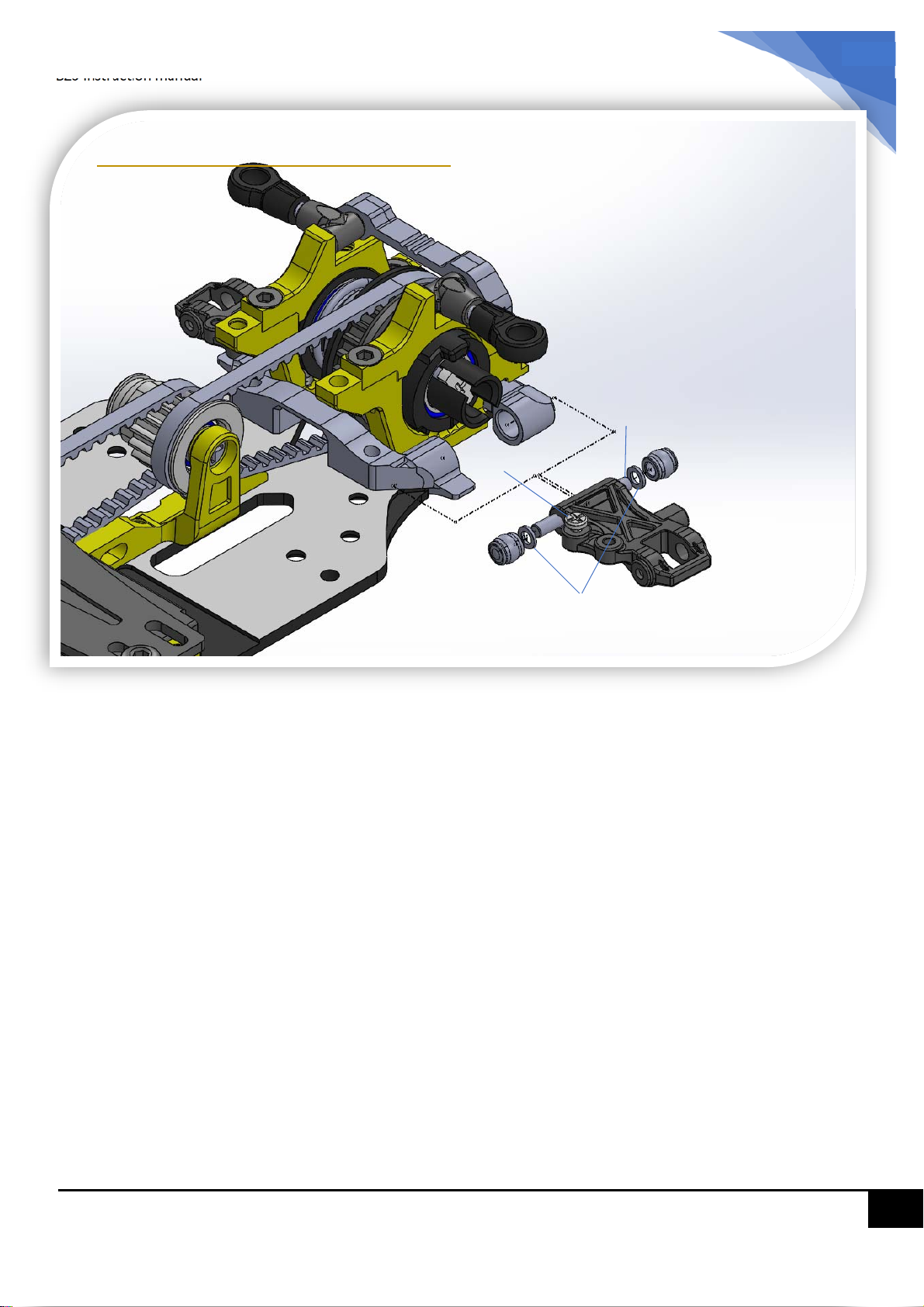
Step 13 – Rear Lower Arms
1.5*13 pin
M1.2*4
3.0 pivot ball
1.5*2.5*0.35 white spacer
16
Page 17
BZ3 Instruction manual
17
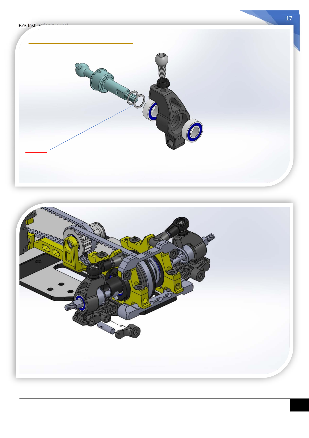
Step 14 – Rear Uprights
Short CVD
3.0 x 4.0 x 0.1 washer
Caution:
Apply 0.1mm washer 2 or 3 pcs (around
0.3mm), to minimize the play of the CVD and
bearing.
3 x 6 x 2 Bearing
3.5 Ball Head
Camber link Collar
3 x 6 x 2 Bearing
2.0*7 pin
Pin cover
17
Page 18
BZ3 Instruction manual
18
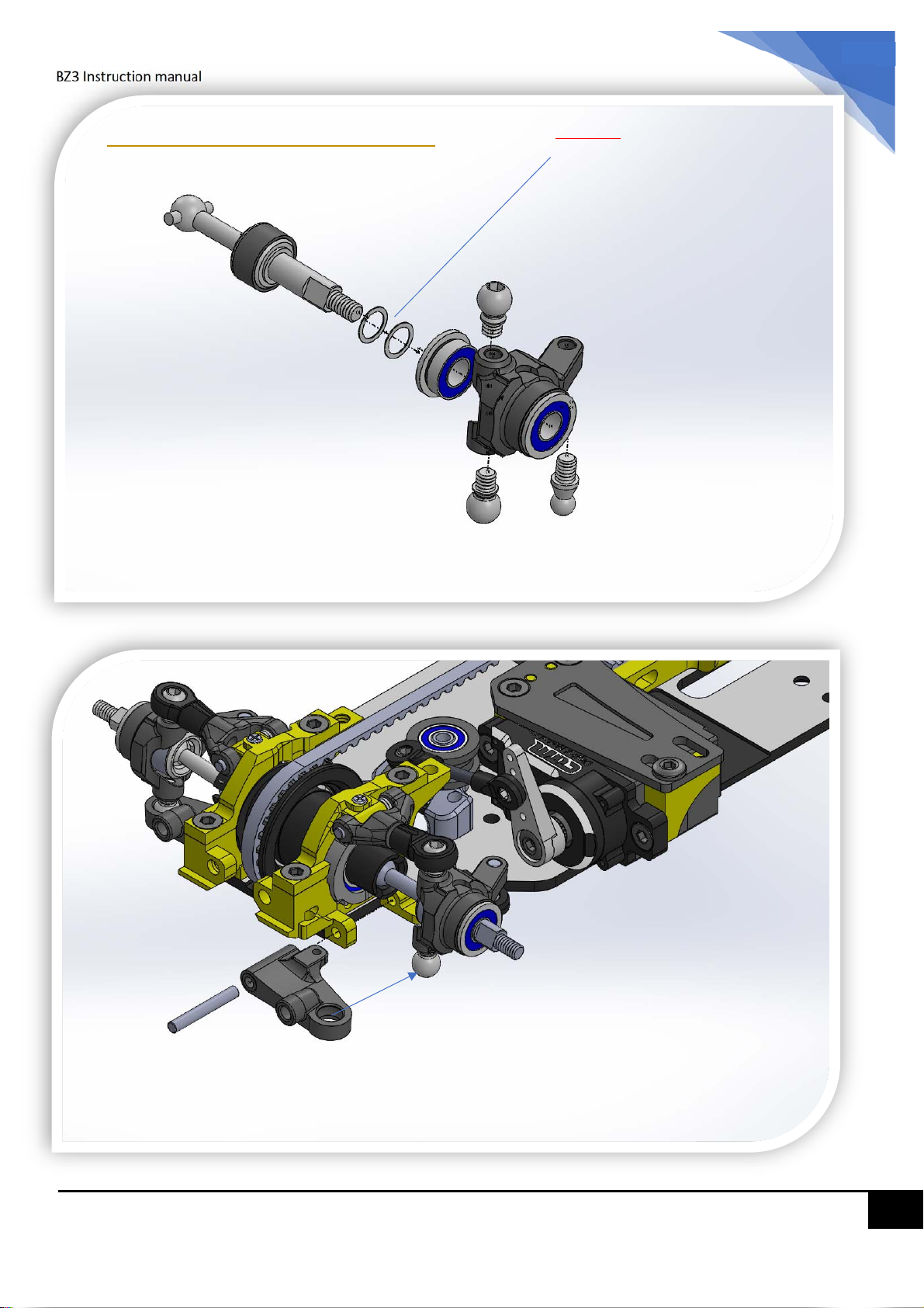
Step 15 – Front Knuckles
Caution:
Apply 0.1mm washer 2 or 3 pcs
Long CVD
(around 0.3mm), to minimize the
play of the CVD and bearing.
3.0 x 4.0 x 0.1 washer
3 x 6 x 2 Flange Bearing
3.5 Ball Head
3 x 6 x 2 Flange Bearing
3.5 Ball Head
2.5 Ball Head
1.5 *12 pin
Left (L) arm
18
Page 19
BZ3 Instruction manual
19
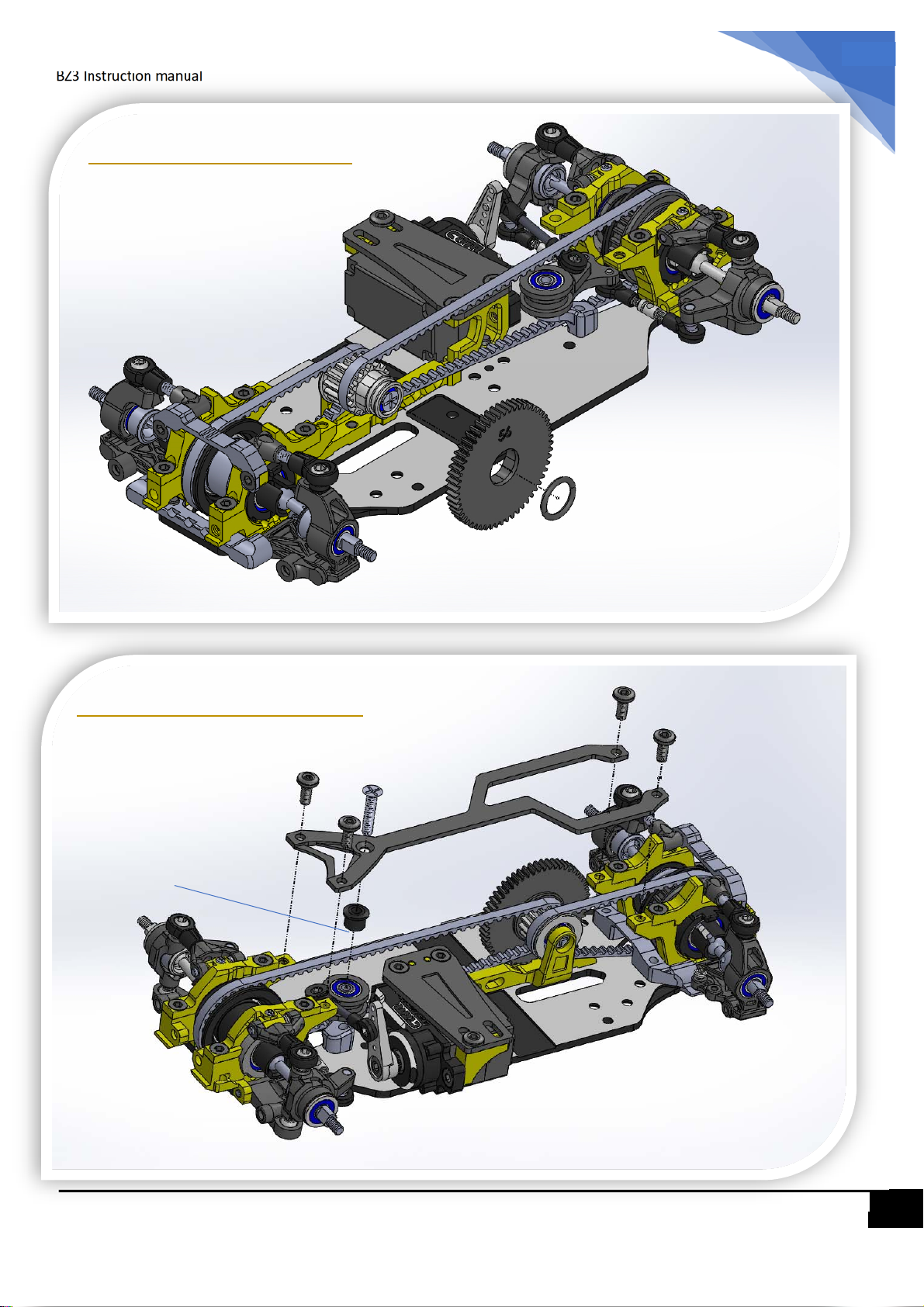
Step 16 – Spur Gear
O-ring (Rubber)
Step 17 – Upper Deck
M2x4
M2x4
Pay attention to the
direction.
M2x4
M2x4
M2 x 10
Steering Collar
19
Page 20
BZ3 Instruction manual
20
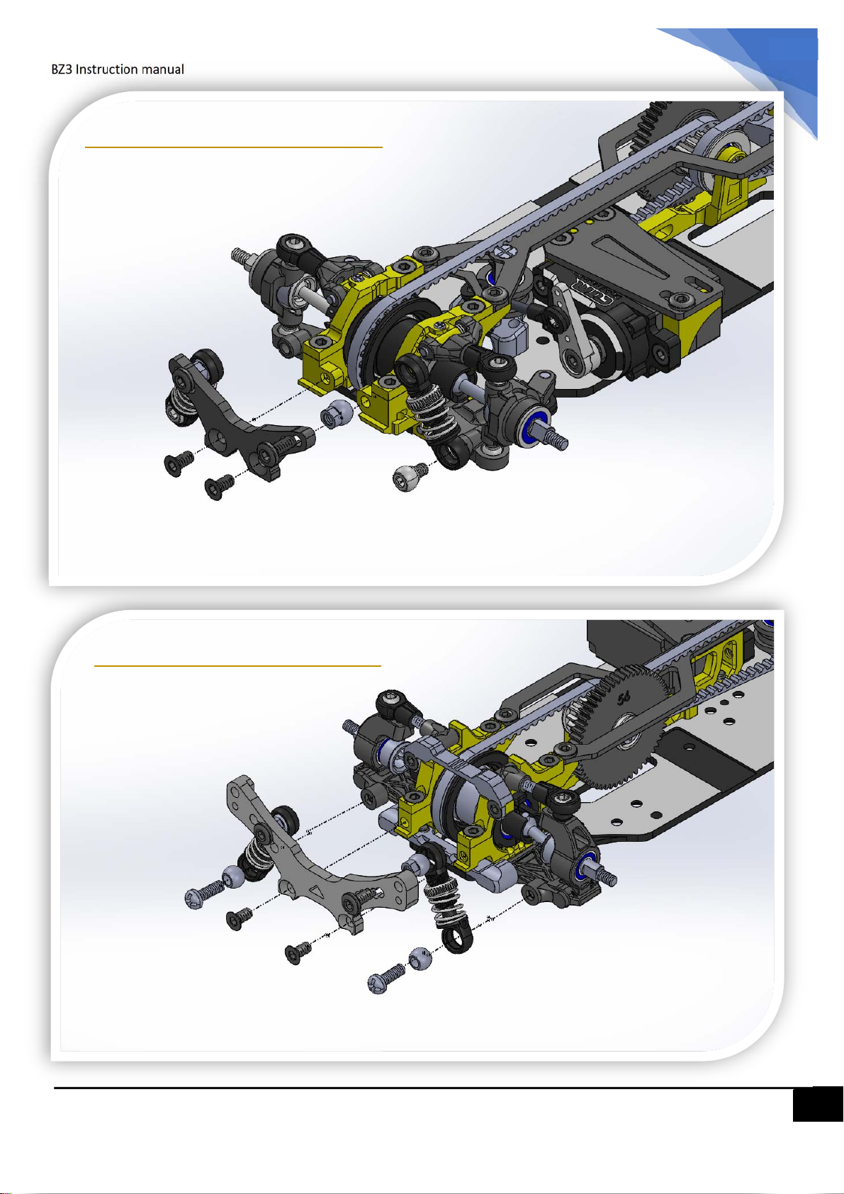
Step 18.1 – Front Shocks
M2x4
4.0mm
M2x4
4.0mm ball head
Step 18.2 – Rear Shocks
M2x4
M2x6
M2x4
M2x4
M2x6
4.0mm ball head
20
Page 21
BZ3 Instruction manual
21
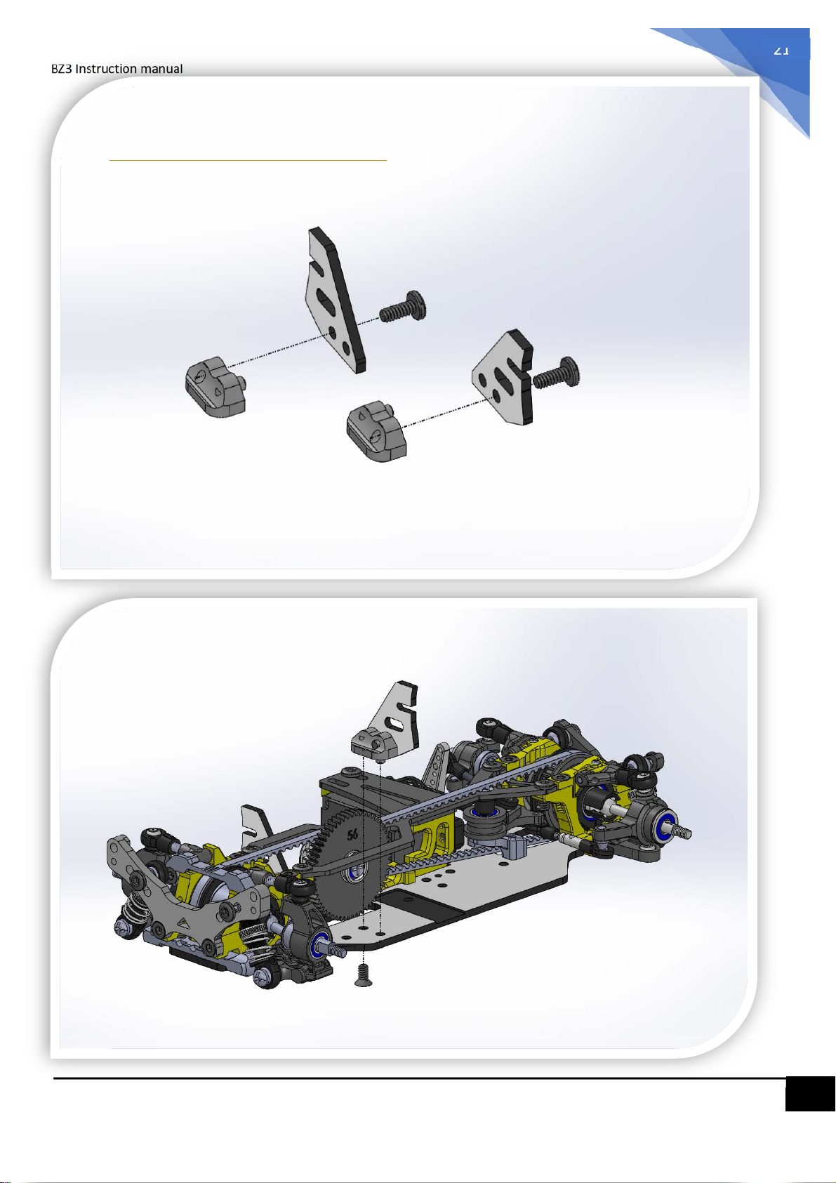
Step 19 – Body Mounts
M2x4
Left Body Mount
M2x4
Right Body Mount
M2x4
21
Page 22
BZ3 Instruction manual
22
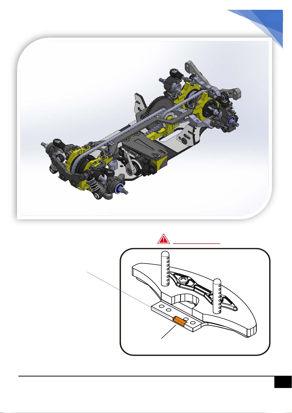
Install the
Front Body Mount
Caution:
Not included
Trim this part to avoid the touch of
front belt
22
Page 23

BZ3 Instruction manual
Step 20 – Gear Ratio
23
Spur
3500KV : around 4.3 ~ 4.6
5500KV : around 5.2 ~ 5.5
1.69
54
56
58
13 14 15 16 17 18 19 20 21
7.54 7.00 6.53 6.13 5.77 5.45 5.16 4.90 4.67
Motor Gear (pinion)
6.76 6.31 5.92 5.57 5.26 4.98 4.73 4.51
Recommend Gear ratio for Atomic Motors:
5.70 5.37 5.07 4.80 4.56 4.35
7000KV : around 5.8 ~ 6.2
Gear ratio decision is affected by strength of battery, chassis weigh and overall smoothness of
the transmission system also the size of the track.
23
 Loading...