

Page 1

USER MANUAL
Page 2

2
TABLE OF CONTENTS
Safety Precautions 2
Warranty Statement 3
Identification of components 4
Pre-operation inspection 6
Operation 7
Starting the engine 8
Using electric power 9
Maintenance schedule 11
Storage 13
Troubleshooting 14
Specifications 15
IMPORTANT INFORMATION
Thank you for purchasing this ATOMIC
Inverter Generator.
This manual covers the safety,
operation and maintenance procedures
for the AI2800X generator.
All information in this publication is based on
the latest product information available at the
time of print. No part of this publication may
be reproduced without written permission.
Please keep this manual together with
the generator.
This generator is designed to give safe
and dependable service if operated
according to the user manual.
It is important that anyone operating this
product read and understand the manual
prior to use. Failure to do so could result in
personal injury or equipment damage.
SAFETY PRECAUTIONS
OPERATIONAL SAFETY
• Always perform a pre-operation
check before starting the engine.
• Properly clean and maintain the generator.
• Operate the generator according to
instructions for safe and dependable service.
• Before operating the generator,
read the user manual carefully.
Otherwise, it may result in personal
injuries or equipment damage.
Do not run the generator indoors or
in an enclosed area to avoid harm or
possible death from exhaust emissions
of poisonous carbon monoxide gas.
• Be careful not to touch the exhaust system
during operation because it can cause burns.
• Pay attention to the warning labels because
the engine exhaust system will become
heated during operation and remain hot
immediately after the engine is stopped.
• Unleaded petrol is a highly flammable
and explosive liquid. Refuel in a well
ventilated area with the engine stopped.
• When refuelling the generator, keep it
away from cigarettes, open flames,
smoke and/or sparks.
• It is recommended that this generator not
be connected for stand-by power to any
household or building electrical circuit.
Improper connections can allow electrical
current from the generator to feed back
into the utility lines and may electrocute
persons contacting the lines during a power
outage. When the utility power is restored,
the generator may explode or cause fires.
• Do not connect the generator to an
ATS automatic transfer switch.
• Place the generator at least 1 metre
away from buildings or other
equipment during operation
• Run the generator on a level surface. If the
generator tilts, fuel spillage may result.
• Know how to stop the generator quickly
and understand the operation of all the
controls. Never permit anyone to operate
the generator without proper instructions.
• Keep children and pets away from
the generator during operation
• Do not operate the generator in rain,
wet conditions or snow.
• Do not allow any moisture to come
in contact with the generator.
• Do not touch the spark plug while the
generator is operating or shortly
after the generator has been shut down.
Page 3

3
SAFETY GUIDELINES
Before connecting any appliances to
the generator:
• Make sure the appliance is turned off.
Faulty appliances or damaged power
cords can lead to an electrical shock.
• Turn off the generator immediately
if the appliance begins to operate
abnormally. Disconnect the appliance
and investigate the problem.
• Make sure that the electrical rating of
the appliance does not exceed that of
the generator. If the power level of the
appliance is between the maximum
output power and the rated power of
the generator, the generator should not
be used for more than 30 minutes.
• Do not connect the AC outlet of the
generator to any household or building
circuits. Improper connections may lead to
a fire hazard or damage to the generator.
MAINTENANCE SAFETY
• Do not clean the air filter element with
flammable liquids like petrol because
an explosion may occur.
• Turn off the generator before performing
any maintenance. Otherwise it can
cause severe personal injury or death.
• Allow the generator to cool down
before performing any maintenance.
• Do not clean the generator with a pressure
washer because it may cause damage.
• Before working with batteries, ventilate
the area, wear safety glasses. Do not smoke
and always disconnect the negative cable
first and reconnect it last.
• Always stop the generator before
removing the oil filler dip stick.
• Only qualified maintenance personnel
with knowledge of fuels, electricity,
and machinery hazards should
perform maintenance procedures.
WARRANTY STATEMENT
Primus Australia warrants this product against
defects for 12 months/500 hours (whatever
period expires first), commencing from
the date of purchase and is for the original
owner only and cannot be transferred.
For all warranty service and repairs
contact Free Call 1300 555 197.
Our goods come with guarantees that cannot
be excluded under the Australian Consumer
Law. You are entitled to a replacement or
refund for a major failure and compensation
for any other reasonably foreseeable loss
or damage. You are also entitled to have
the goods repaired or replaced if goods fail
to be of acceptable quality and the failure
does not amount to a major failure.
Proof-of-purchase or a sales receipt clearly
showing the date and details of the purchase
is required for all warranty service or repair.
Primus Australia will repair or replace the
product, at its discretion, should a warrantable
defect arise within the warranty period. If
the exact model is unavailable a model of
equivalent value or features will be substituted
at our discretion. This warranty excludes faults
and failures caused by improper use and
abuse; fair wear and tear; or failure to follow
instructions regarding care and maintenance.
It is at the discretion of Primus Australia if
a warranty or replacement will be issued
once the product has been inspected
by an authorised repair agent and
deemed to be a genuine warranty.
Primus Australia will not be liable for any
costs, charges or expenses incurred in the
process of having the product returned to
the place of purchase in order to request
a warranty unless agreed to in writing
prior to the product being returned.
For a copy of the warranty policy please visit
our website www.primusaustralia.com.au
Alternatively email service@primusaustralia.
com.au for further information.
Page 4
4
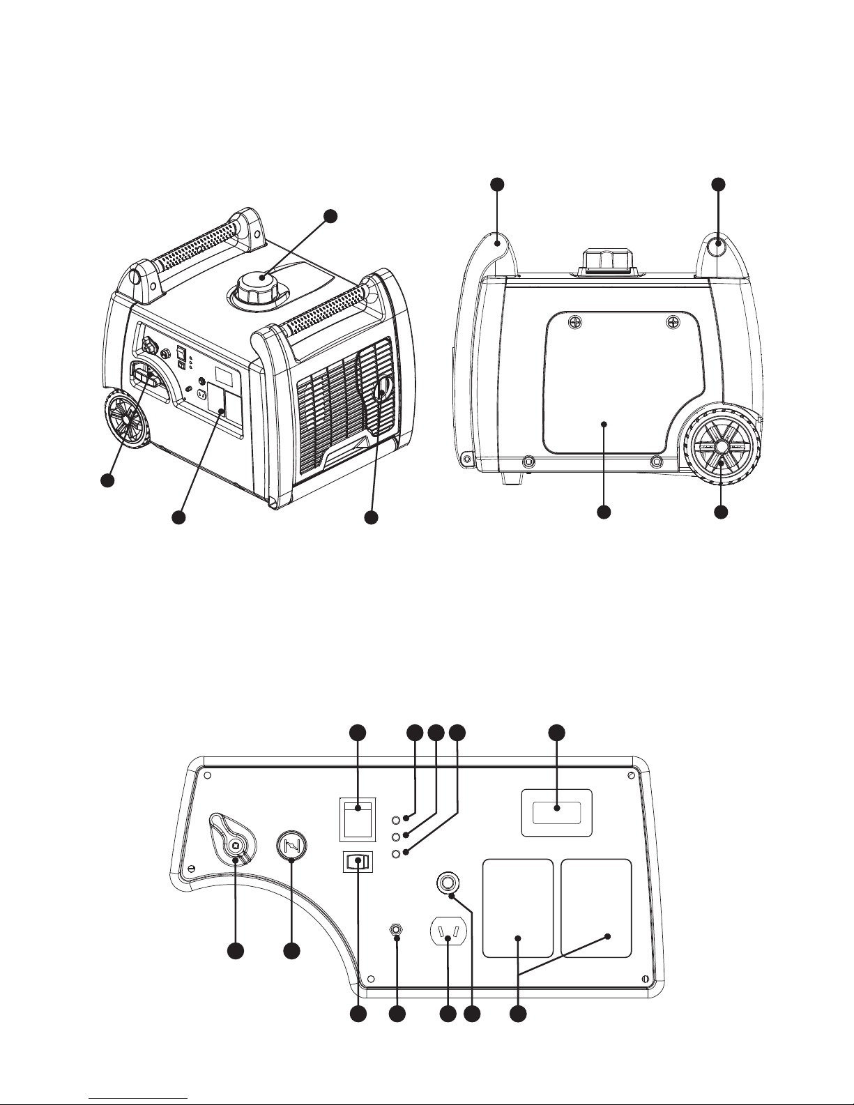
IDENTIFICATION OF COMPONENTS
7 7
3 4
2
1
5 6
9
10 11 12 14
1519 18 17 16
13
8
1 Fuel Tank Cap
2 Recoil Starter Handle
3 Control Panel
4 Muffler
5 Side Maintenance Cover
6 Solid Wheels
7 Carrying Handle
8 Fuel Tap Knob
9 Choke
10 Economy Control Switch
11 Ground Terminal
12 12V DC Socket
13 Circuit Breaker (Push Button)
14 240 Volt AC 15A Outlets
15 Hour Meter
16 Oil Alert Warning Light
17 Overload Indicator Light
18 Output Light
19 Engine Switch
Page 5
5
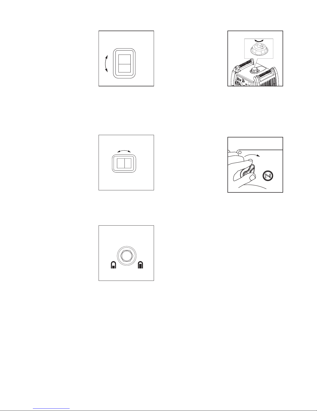
ENGINE SWITCH
The engine switch
controls the
ignition system.
• ON (run)
Ignition circuit
is switched on.
The engine can
be started.
• OFF (STOP) Ignition circuit is switched
off. The engine will not run.
ECONOMY CONTROL SWITCH
When the economy control switch is pressed
ON, the economy
control unit controls
the engine speed
according to the
connected load.
This maximises the
fuel efficiency of
the generator.
DC CIRCUIT BREAKER
The DC circuit breaker turns off automatically
when the load exceeds the generator
rated output.
CAUTION: Reduce
the load to within
specified generator
rated output if
the DC circuit
breaker turns off.
FUEL TANK CAP AIR VENT
The fuel tank cap
is fitted with an air
vent. The air vent
must be turned to
the ON position to
start the generator.
This will allow
fuel to flow to the
carburettor and the
engine to run.
When the generator is not in use,
turn the air vent knob to OFF.
FUEL TAP
The fuel tap is
used to supply fuel
from the tank to
the carburettor.
ONI
O
OFF
ENG
ON
I
O
OFF
ECON
DC CIRCUIT
BREAKER
ON PUSH OFF
O
F
F
O
N
ON OFF
ON
Page 6
6
PRE-OPERATION INSPECTION
Exhaust gas contains poisonous carbon
monoxide. Do not run the generator in an
enclosed area. Be sure to provide adequate
ventilation. Operate the generator on a
clean, dry and level surface. If the generator
is tilted, fuel spillage may result in fire.
The generator is air-cooled and may be
damaged if ventilation is inadequate.
Inspect the engine oil before use. Engine oil
is a major factor affecting the performance
and service life of this product.
Non-detergent, 2 stroke engine oil or
vegetable oils are not recommended.
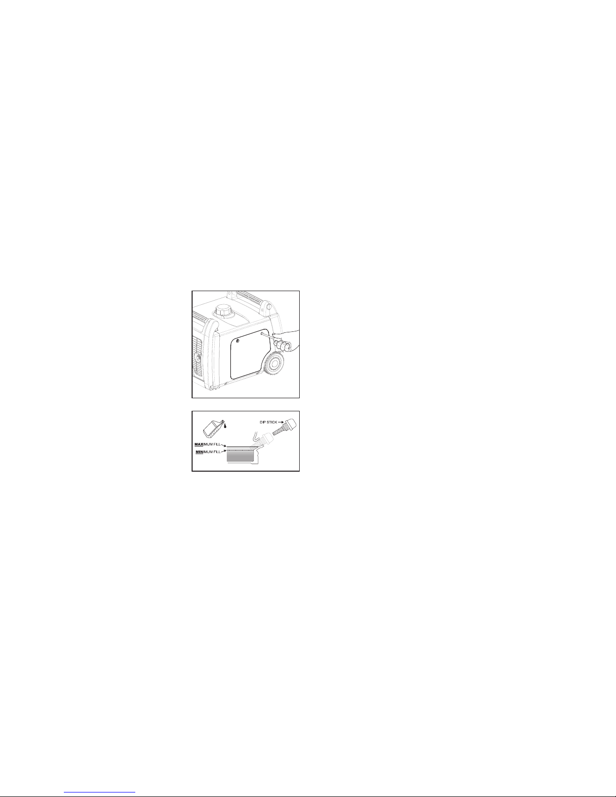
CHECKING OIL LEVEL
• Unscrew the
side cover.
• Remove the oil
filler dipstick
and clean.
• Check the oil level
by reinserting
the oil filler
dipstick. Remove
and examine
the oil level. If
the level is at or
below the lower
level mark, refill
the oil to the upper limit mark. Use SAE
10W30 or 15W40 oil for this generator.
• Reinsert the oil filler dipstick and
tighten securely.
• Refit the side cover.
Running the engine with insufficient oil
can cause serious damage to the engine
and other important components.
When the oil level is low, the Low Oil
Warning Light on the control panel will
illuminate and the engine will automatically
shut down. Do not restart the generator
until the oil level has been topped up.
CHECKING FUEL LEVEL
• Use only clean, fresh unleaded petrol.
Do not use E10 (Ethanol) fuel.
• Check the fuel level by removing the
fuel tank cap to visually inspect.
• Add fuel if level is too low. Do not
refuel while generator is running.
Tighten the cap securely after filling.
Petrol is highly flammable and explosive
under certain conditions. Refuel in a wellventilated area with the engine stopped. Do
not smoke or allow open flames or sparks in
the area where the generator is refuelled or
where petrol is stored. Do not overfill the tank.
Be careful not to spill fuel when refuelling.
Wipe up any spilled petrol and let the area dry
before starting the engine. Do not use an oil/
petrol mixture, dirty or contaminated petrol.
Keep out of the reach of children.
Fuel system damage or engine performance
problems resulting from the use of fuel other
than clean, fresh unleaded petrol
are not covered under warranty.
CHECKING AIR FILTER
1. Unclip the locking hinge on the Air
Filter cover. Take out the Air Filter
element and inspect for cleanliness.
2. Replace the air filter element if dirty
or damaged. It is recommended
to check their air filter element
every 3 months or 50 hours.
3. Refit the air filter element and
securely fasten the air filter cover.
DC12V BATTERY CHARGE SOCKET
The DC12V battery charge socket can
be used with the battery leads (supplied) to
charge 12 volt automotive batteries only.
There is a DC12V circuit breaker protecting the
socket. If an overload is detected, the reset
button will pull out to the OFF position. To
reset, push in the button to the ON position.
Note: The DC12V battery charge socket can
be used while the AC power is in use.
Page 7
7
OPERATION
PRE-OPERATION CHECKS SHOULD BE MADE
EACH TIME THE GENERATOR IS USED.
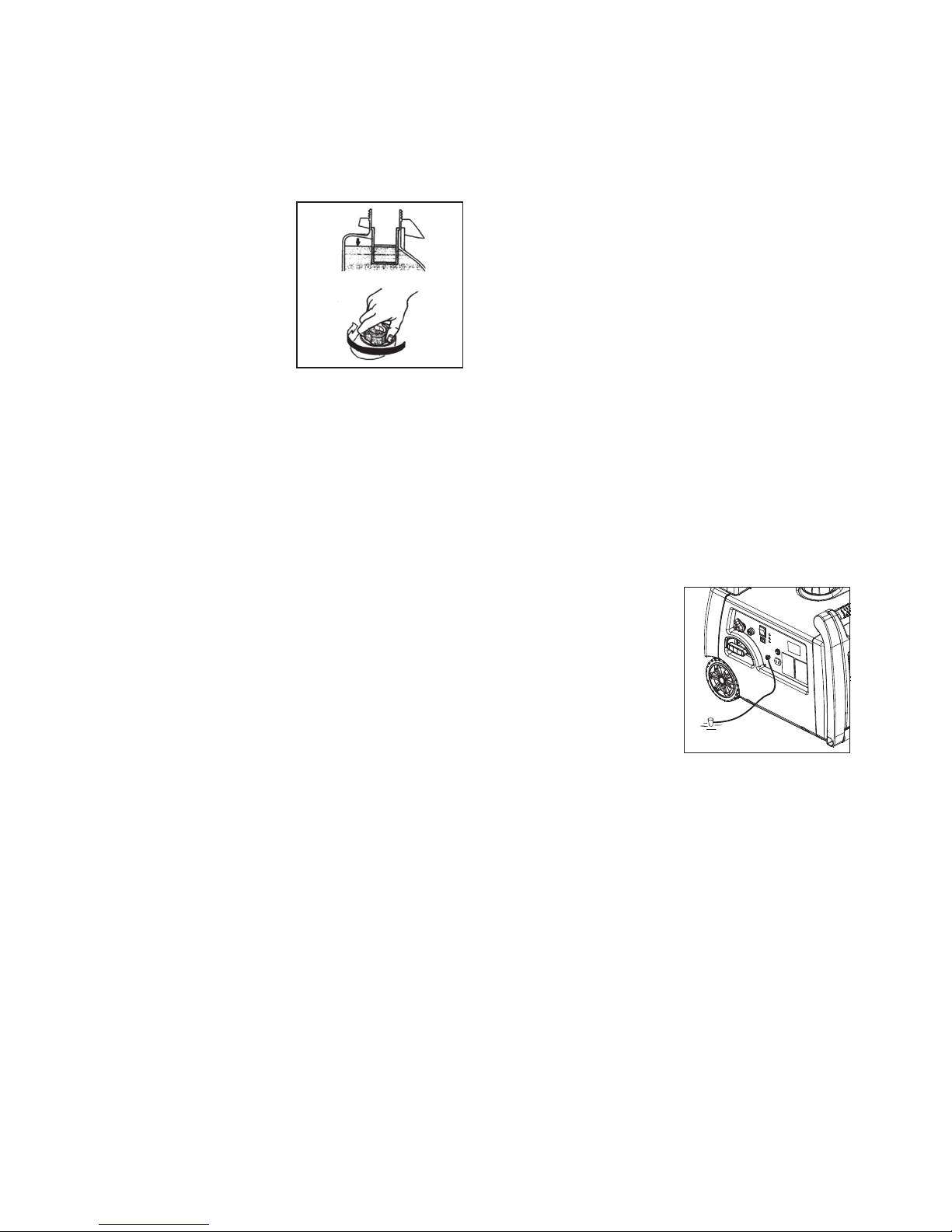
ENGINE FUEL
• Make sure there
is sufficient fuel
in the tank.
• If fuel is low,
refill with
unleaded petrol.
• Be sure to use
the fuel filter
screen inside
the fuel tank.
• Fuel: Only use clean, unleaded petrol.
• Fuel tank capacity: 6.0L
WARNING:
• Do not refill fuel tank while
engine is running or hot.
• Turn off Fuel Tap before refueling.
• Be careful not to allow dust, dirt, water
or other foreign objects into fuel.
• Do not fill above the top of the fuel filter.
• Wipe off spilt fuel thoroughly
before starting generator.
• Keep open flames away.
ENGINE OIL
This generator has been supplied without
engine oil. Fill with oil or it will not start.
Do not tilt the generator when adding
engine oil. This could result in overfilling
and damage to the engine.
In regular use, make sure the engine oil is at
the upper level of the oil filler dipstick before
starting the generator. Add oil as necessary.
• Remove oil filler dipstick and
check the engine oil level.
• If oil level is below the lower level line,
refill with recommended oil to upper
level line. Do not screw in the oil filler
dipstick when checking oil level.
• Change oil if contaminated.
• Oil capacity: 600ml
• Recommended engine oil:
SAE 10W30 or 15W40
GROUNDING (EARTH)
Make sure the
generator is
grounded (earthed)
when in use to help
prevent electric
shock. A ground
terminal has been
provided on the
control panel.
Use a heavy gauge ground cable with
current capacity of 20 Amp and a
copper rod driven into the ground.
Page 8
8
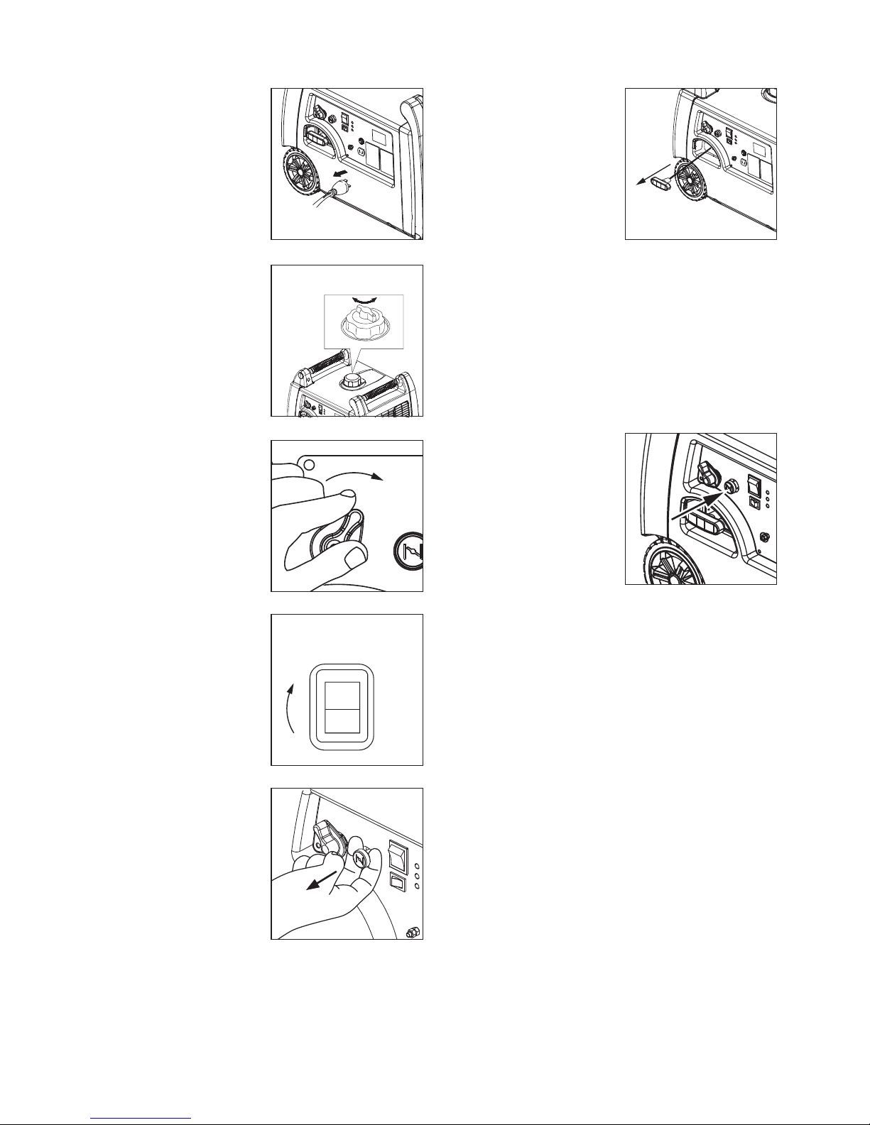
STARTING THE ENGINE
NOTE:
Before starting
the engine, do
not connect any
electrical appliances.
1. Turn the fuel cap
air vent to ON.
2. Turn the fuel
tap to ON.
3. Press the engine
switch to ON.
4. Pull out the
choke. This is not
necessary if the
engine is warm.
5. When starting
the generator
for the first time
after refilling, pull
the recoil handle
approximately 6
times. This will
pump fuel up to
the carburettor.
6. Pull the recoil starter handle slowly until
resistance is felt. Return the handle
to its original position and pull out
firmly. After starting, allow the starter
handle to return to its original position
while still holding the handle.
7. Warm up the engine.
8. Push the choke
back in to the
RUN position.
9. Warm up the
engine for a few
minutes before
plugging in any
appliances.
O
F
F
O
N
ON
ON
ONI
O
ENG
Page 9
9
USING ELECTRIC POWER
AC APPLICATION
1. Check the AC output light (green)
is on and illuminated.
2. Turn off electrical appliances before
connecting to the generator.
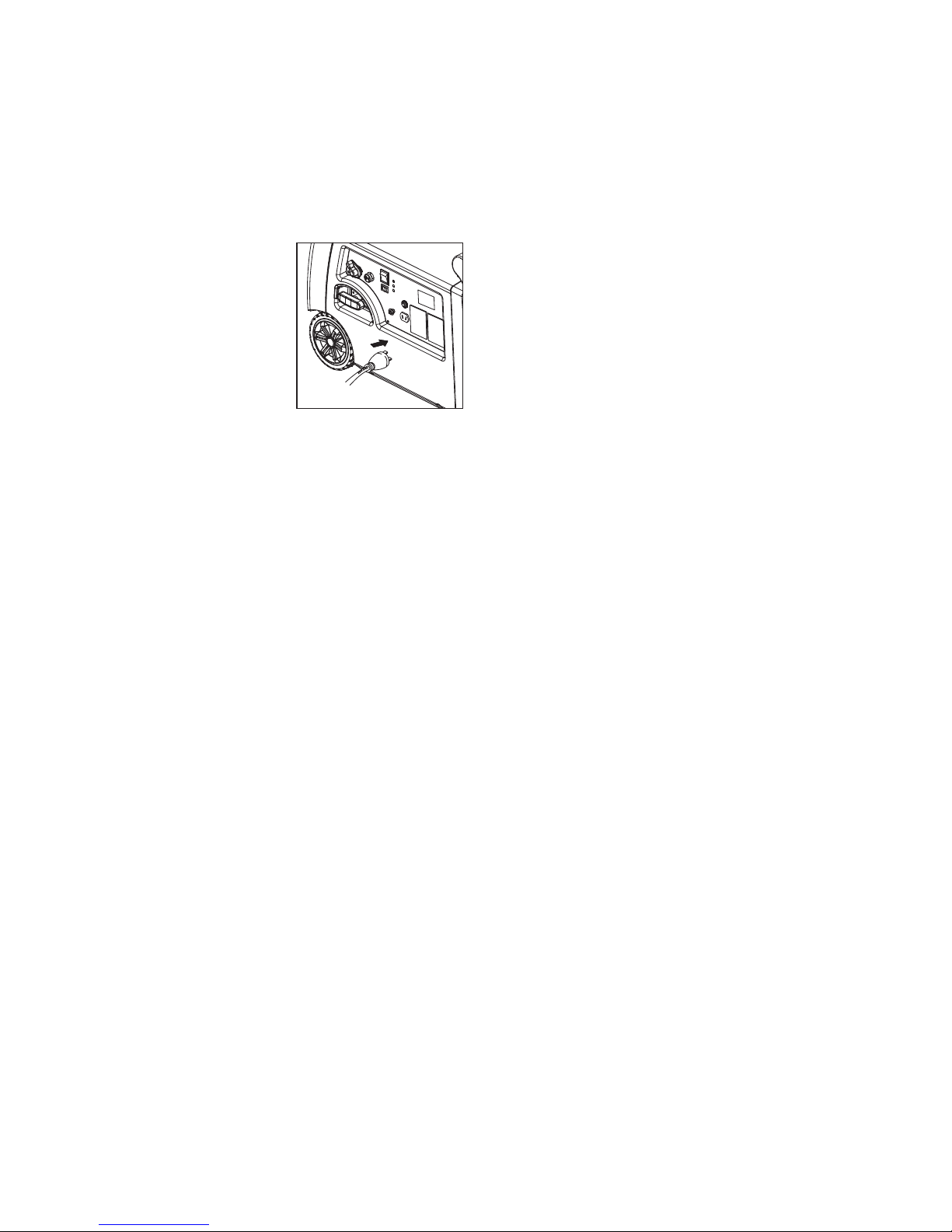
3. Insert the plug
of the electrical
appliance into
the AC socket.
CAUTION:
• Ensure the electric
appliances
are turned off
before plugging into the AC socket.
• Ensure the total load is within
the generator rated output.
DO NOT OVERLOAD GENERATOR
• Follow these steps to calculate
the running and starting watts
required for your appliances
1. Select the appliances you plan on
running at the same time
2. Total up the running watts
of these appliances
3. Identify the starting wattage of the selected
appliances and add this amount to the total
running watts - refer to the manufacturers
label or name plate on the appliance. The
extra burst of power needed to start some
electric motor driven appliances may be
up to three times the running watts.
4. To convert voltage and amperage to watts:
Volts (V) x Amps (A) = Watts (W)
OVERLOAD INDICATOR LIGHT
The overload indicator light (RED) comes
on when the rated load is exceeded.
When the maximum load is reached, the
RED light will blink and cut power to the
AC outlets to protect the generator and
any connected electric appliances.
To recover the power, turn off the
engine, wait until the RED light turns
off and then restart the generator.
Check the following steps:
• Turn off all connected electric appliances
• Reduce the total wattage of
connected electric appliances
within the rated load range.
• After restarting the generator, check
that the GREEN output light is now on
(illuminated). Plug in appliances.
CAUTION:
• The generator AC output automatically
resets when the engine is
stopped and then restarted.
• The overload indicator light may
come on for a few seconds at first
when using electric appliances that
require a large starting current.
However, this is not a malfunction.
Page 10
10
DC APPLICATION
This usage is applicable to 12V
battery charging only.
CHARGING INSTRUCTION FOR 12V DC BATTERY
• Disconnect the leads for the battery.
• Remove the battery filler cap.
• Fill distilled water to the upper limit,
if the battery fluid is low level.
• Measure the specific gravity for the
battery fluid by using a hydrometer
• Connect the DC output socket and the
battery terminals using the charging
leads. The leads shall be connected
making sure of the (+) and (-) polarity.
• Check the DC circuit breaker is set to
ON to start charging the battery.
CAUTION:
Turn off the economy control switch
while charging the battery.
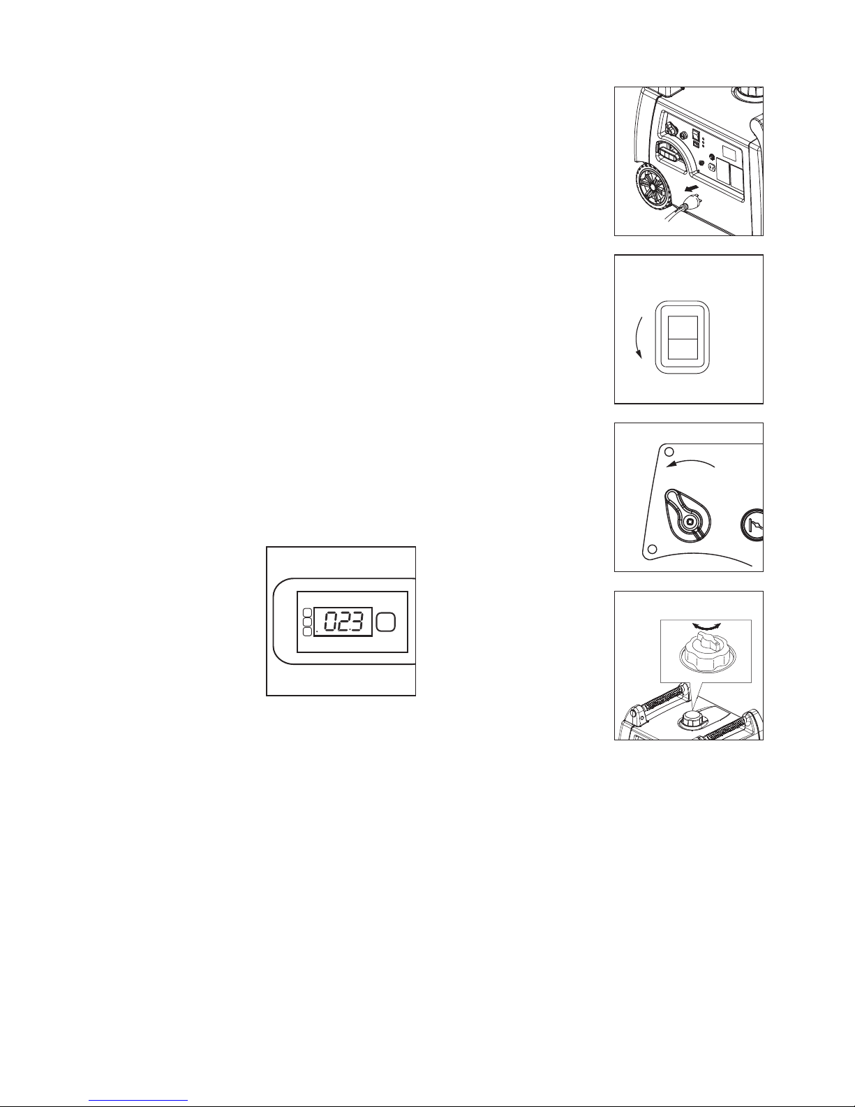
HOUR METER
By pressing the
SELECT button, the
digital 3 in 1 hour
meter will display:
V = Volts
Hz = Frequency
H = Run time hours
Note:
It is recommended to use the total
run time hours as a guide for the
maintenance schedule: refer page 11.
STOPPING THE ENGINE
1. Turn off and
disconnect all
electric appliances.
2. Press the engine
switch to OFF.
3. Turn the fuel
tap to OFF.
4. Turn the fuel tank
cap air vent to
the OFF position.
I
O
OFF
ENG
OFF
O
F
F
O
N
OFF
V
SELECT
Hz
H
Page 11

11
MAINTENANCE SCHEDULE
Regular maintenance is most important for the maximum
performance and safe operation of the generator.
ITEM TASK DAILY
1ST MONTH
OR
10 HOURS
EVERY 3
MONTHS OR
50 HOURS
EVERY 6
MONTHS OR
100 HOURS
EVERY 12
MONTHS OR
300 HOURS
General Inspection
Spark Plug
Check condition,
adjust gap, clean
REPLACE
Engine Oil*
Check oil level
Replace
*
Air Filter
Clean, replace
if necessary
Fuel Filter
Clean, replace
if necessary
Choke Check operation
Valve
clearance
Check and adjust
when engine is cold
Fuel Line
Check hose for
damage, replace
if necessary
Exhaust
System
Check for leakage,
retighten or replace
gasket if necessary
Check spark arrestor,
clean or replace
if necessary
Cooling
System
Check fan for damage
Starting
System
Check recoil starter
operation cord
and handle
Idle Speed
Check and adjust
engine idle speed
Fittings/
Fasteners
Check and tighten
if necessary
Crankcase
Breather
Check hose for
cracks or damage,
replace if necessary
* Note: it is recommended to replace the engine oil and clean oil filter after the first 10 hours of operation
and then every 50 hours.
Page 12
12
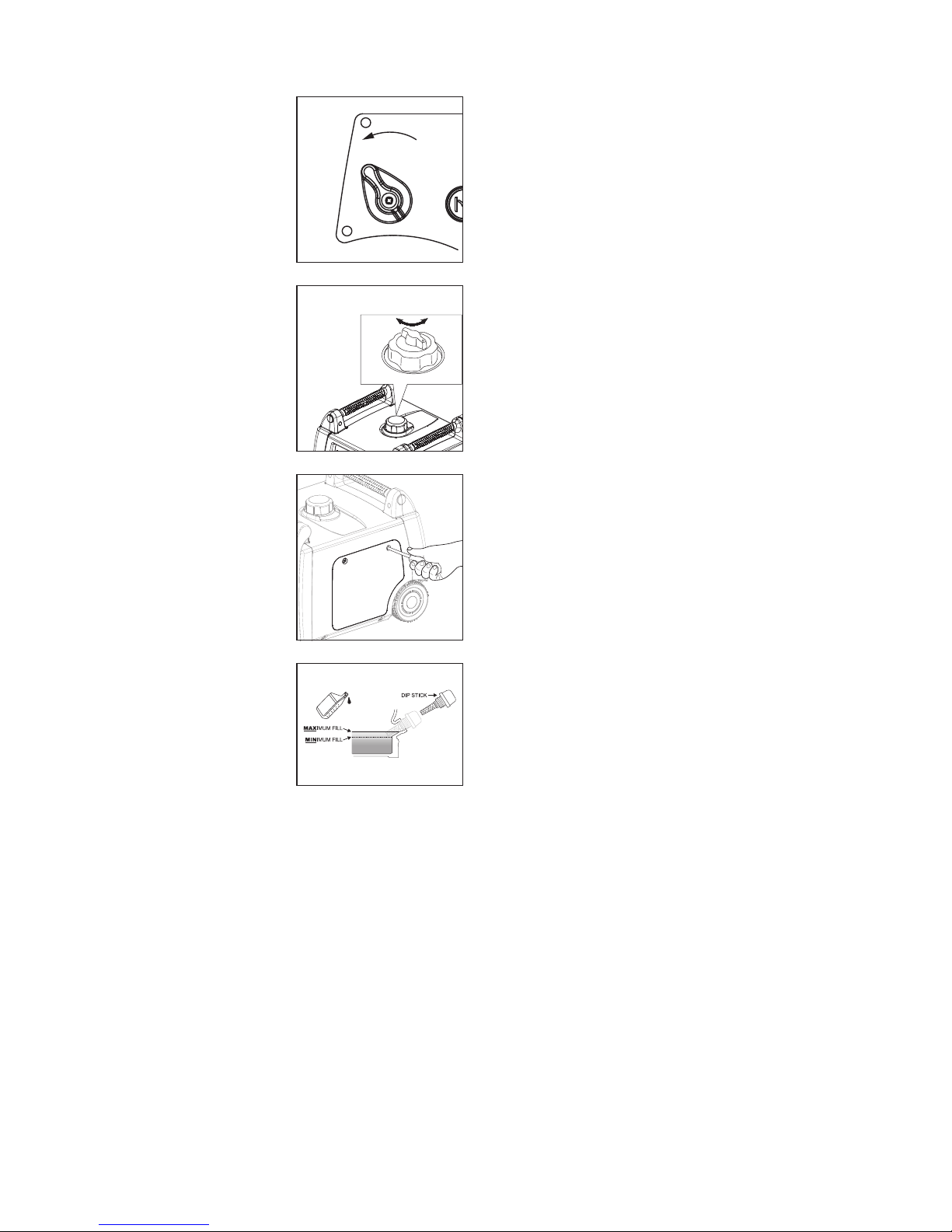
ENGINE OIL REPLACEMENT
1. Place the
generator on a
level surface and
warm up the
engine for several
minutes. Then
stop the engine
and turn the
fuel tap to OFF.
2. Turn OFF the fuel
tank cap air vent.
3. Remove the
side cover.
4. Remove the oil
filler dipstick and
12mm hex drain
bolt at the bottom
of the engine.
5. Place an oil pan
under the engine.
Tilt the generator
to drain the oil
completely.
6. Place the
generator on a
level surface and
refit drain bolt.
7. Add engine oil to
the upper level.
Use SAE10W30 or
15W40 grade oil.
8. Install the oil filler dipstick securely.
9. Re-fit the side cover and tighten the screws.
CAUTION
• Ensure no foreign material
enters the crankcase.
• Do not tilt the generator when
adding engine oil. This could result in
overfilling and damage to the engine.
AIR FILTER
A dirty air cleaner will restrict air flow to
the carburettor and increase engine wear.
Clean and service the air cleaner regularly
- more frequently when operating
generator in extremely dusty conditions.
1. Remove side cover.
2. Locate air filter plastic cover. Unclip
the locking hinge on the cover.
3. Remove the air filter element.
4. Inspect the air filter element.
Replace if dirty or damaged.
5. Refit the air filter element into the air
filter housing, re-snap the locking hinge
and re-install side cover securely.
CAUTION:
The engine should never run without
the air cleaner element; excessive
engine wear may result.
OFF
O
F
F
O
N
OFF
Page 13
13
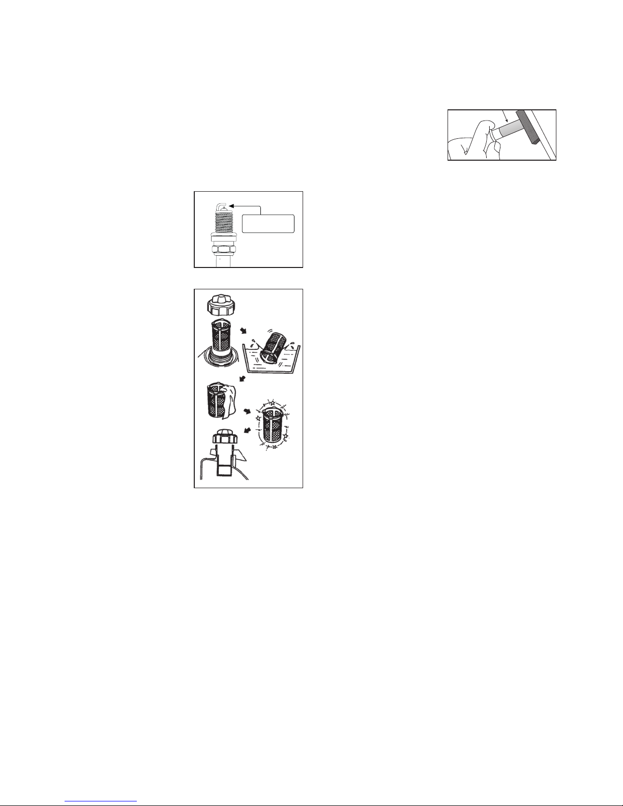
CLEANING AND ADJUSTING SPARK PLUG
1. Remove the side cover.
2. Remove the spark plug cable
from the spark plug.
3. Use spark plug spanner to
remove the spark plug.
4. Clean and check spark plug gap.
5. Re-fit the spark plug and cable.
6. Replace spark plug
every 12 months.
Use:
BPR6ES (NGK)
7. Re-fit the spark
plug cover.
FUEL TANK FILTER
1. Remove the fuel
tank cap and filter.
2. Clean the filter
with solvent.
Replace if
damaged.
3. Re-fit the filter.
WARNING
Be sure the tank
cap is tightened
securely.
MUFFLER SCREEN AND SPARK ARRESTOR
WARNING
• The engine and muffler will be very
hot after the engine has been run.
• Avoid touching the engine and
muffler while they are still hot with
any part of your body or clothing
during inspection or repair.
1. Remove the two screws holding the
cover plate which retains the end of
the spark arrestor to the muffler.
2. Remove the spark arrestor mesh screen.
3. Carefully remove
the carbon
deposits from
the spark arrestor
using a wire brush.
4. Replace the spark arrestor if damaged.
5. Re-fit the spark arrestor and
attach using the two screws.
STORAGE
The generator should be started at least
once every 14 days and allowed to run for
approximately 20 minutes. Long term storage
of your generator will require some preventive
procedures to guard against deterioration.
DRAIN THE FUEL
1. Remove the fuel tank cap, drain
the fuel from the fuel tank
2. Remove the side cover, drain fuel from the
carburettor by loosening the drain screw.
3. Turn fuel tap OFF.
ENGINE
1. Remove the spark plug, pour in
about 15ml of SAE 10W30 or 15W40
motor oil into the spark plug hole.
2. Use the recoil starter to turn the engine over
several times (with engine switch off).
3. Re-install the spark plug.
4. Pull the recoil starter handle until
you feel compression, then stop.
5. Clean exterior of the generator.
6. Store the generator in a dry, wellventilated area. Cover the generator.
0.7-0.8 mm
0.028-0.031 in.
Page 14
14
TROUBLESHOOTING
Common issues can be fixed by following
the instructions in this guide. If the generator
will not operate normally after following
these instructions, contact an authorised
dealer or qualified technician before
attempting to use or carry out any repairs.
Many troubleshooting procedures
present hazards which can result in
severe personal injury or death.
Only trained and experienced service
personnel with knowledge of fuels, electricity,
and machinery hazards should perform
service procedures. Review Safety Precautions.
A hot generator can cause severe burns.
Always allow the generator to cool before
performing any maintenance service.
For all warranty, service and repairs
contact Free Call 1300 555 197.
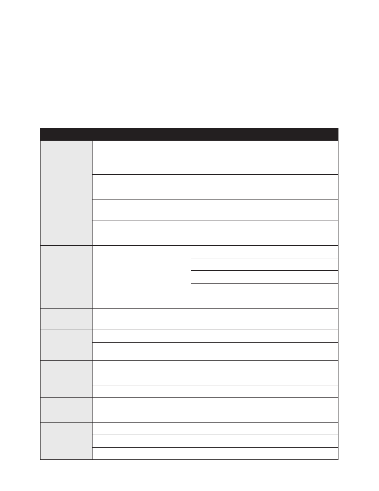
ISSUE CAUSE ACTION
Generator is
not working
Engine switch is OFF Turn engine switch ON
No fuel
Fill with unleaded petrol, pull Recoil Starter
Handle 6 times to prime carburettor
Fuel tap is OFF Turn fuel tap to ON
Fuel tank cap vent closed Turn fuel tank cap vent to ON
Choke in the wrong position
Pull CHOKE to START - push in
to RUN when started
Low engine oil alert light ON Add engine oil to high level on dipstick
Spark plug fouled Remove, clean or replace spark plug
Generator
runs but no
power output
Red overload light is on
Disconnect appliances and stop generator
Re-start and check if GREEN output light on
Check appliances before reconnecting
Do not overload generator
Take generator to an authorised service agent
No 12 volt
output
DC circuit breaker is “Off”
Push and re-set DC circuit breaker to “ON”
Reduce DC load
Engine
cranks
slowly
Engine oil is too heavy Replace with recommended oil
Load is connected Disconnect all appliances from the front panel
Black
Exhaust
Choke stuck in closed position Open choke
Dirty air cleaner Clean air filter
Rich fuel mixture Contact an authorised dealer
Engine
Stops
No fuel Refill tank
Not enough oil Add more oil to high level on dipstick
Engine has
difficulty
idling
Loose spark plug cable Reconnect or repair cable
Faulty spark plug Remove, clean or replace spark plug
Generator is not level Move generator to a level surface
Page 15
15
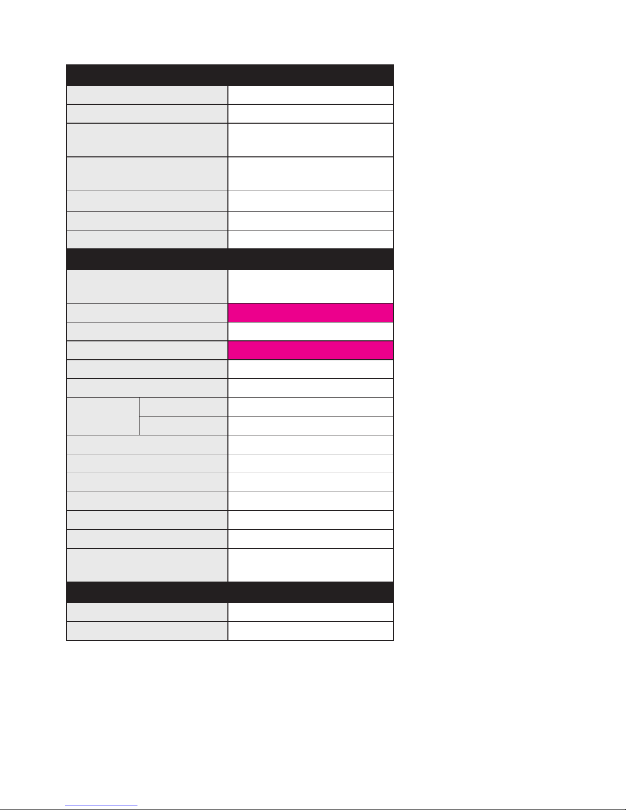
SPECIFICATIONS
Generator AI2800X
Type Digital Invertor Generator
AC Voltage 240V @ 50Hz
Rated Output
(Continuous Power)
2800W
Maximum Output
(Peak Power)
3100W
Rated Current 11.7A
Power Factor 1.0
DC output 12V
Engine
Type
Air cooled, O.H.V. 4-stroke
petrol engine
Bore x Stroke
Displacement 171cc
Max. Output
Fuel Unleaded petrol
Fuel tank capacity 6.0L
Continuous
run time
@ 100% load 3.4hr
@ 50% load 5.4hr
Noise level (full load) @ 7m 67dB
Lubricating oil SAE 10W30 or 15W40
Lubricating oil capacity 0.6L (600ml)
Starting system Recoil starter
Ignition system Electronic
Spark plug type BPR6ES (NGK)
Valve clearance
Inlet: 0.06 - 0.12mm
Exhaust: 0.08 - 0.14mm
Dimensions
Net dimension 570L x 440W x 470Hmm
Net weight 38.0kg
* Specifications are subject to change without prior notice
Page 16

Distributed by Primus Australia Pty Ltd
Bundoora, VIC. 3083. www.atomicgenerators.com.au
ATM028
 Loading...