

Page 1
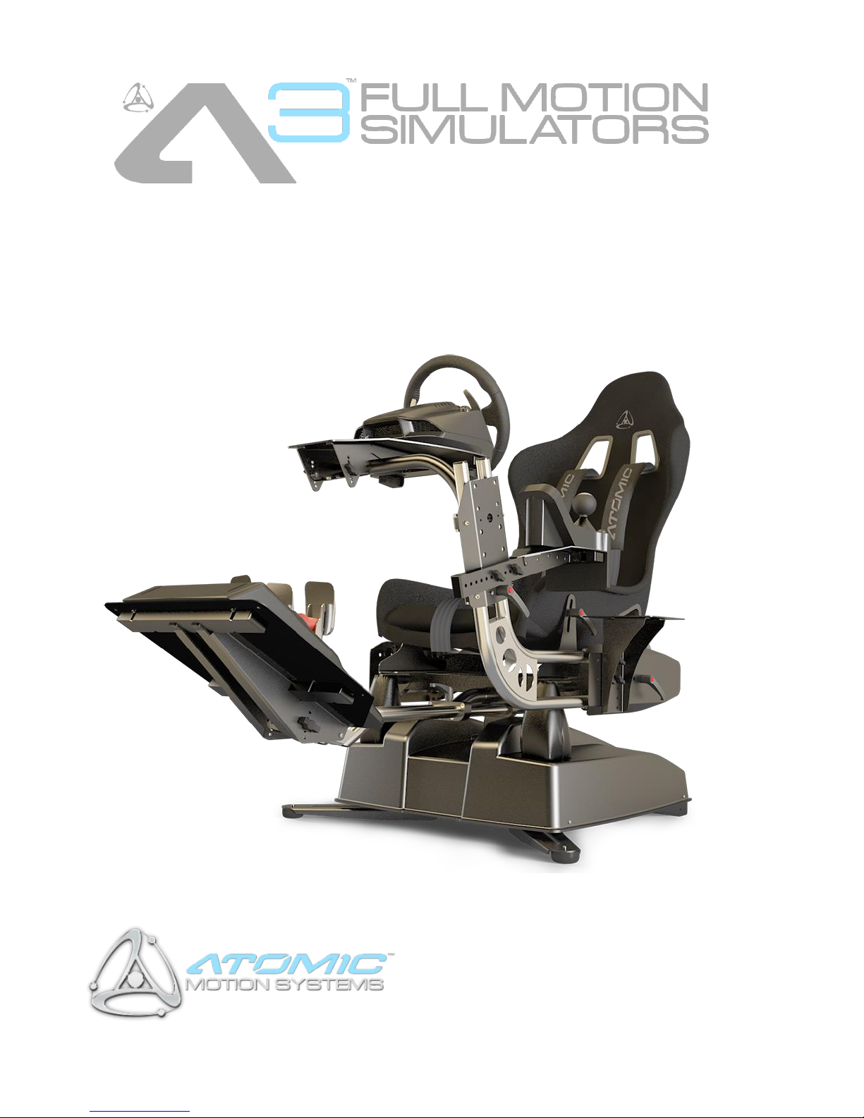
Assembly & Instruction Manual
Page 2

2
A3 Motion Simulators, Assembly & Instruction Manual, November 2018
Contents
1 Disclaimer ................................................................................................................................................... 4
2 Unpacking Checklist ................................................................................................................................... 5
2.1. System Components ........................................................................................................................... 5
2.2. Tools Required..................................................................................................................................... 5
2.2.1. Additional Recommended Tools .................................................................................................. 5
3 Motion Base Setup ..................................................................................................................................... 6
3.1. Seat Installation & Adjustment ........................................................................................................... 6
3.2. Tactile Transducers ............................................................................................................................. 7
3.3. Support Legs ........................................................................................................................................ 7
3.4. Seat Adjustment .................................................................................................................................. 7
4 Foot Rest / Pedal Mount Installation & Adjustment ................................................................................. 8
4.1. Installation ........................................................................................................................................... 8
4.2. Reach Adjustment ............................................................................................................................... 8
4.3. Tilt Adjustment .................................................................................................................................... 9
5 Steering Wheel / Yoke Mount Installation & Adjustment ......................................................................... 9
5.1. Installation ........................................................................................................................................... 9
5.2. Reach Adjustment ............................................................................................................................. 10
5.3. Height Adjustment ............................................................................................................................ 10
5.4. Tilt Adjustment .................................................................................................................................. 11
6 Shifter / Throttle / Switch Panel Mount Installation & Adjustment ........................................................ 11
7 Side Mount Installation & Adjustment .................................................................................................... 11
8 Centre of Gravity (COG) Setup ................................................................................................................. 12
9 Wiring (Rear IO Panel) ............................................................................................................................. 13
9.1. Basic Setup ........................................................................................................................................ 13
9.1.1. Amplifier Wiring (TTi Units Only) ............................................................................................... 14
10 Operation ................................................................................................................................................. 14
10.1. Power ............................................................................................................................................. 14
10.2. Safety Interlock System ................................................................................................................. 15
10.3. Indicator LEDs ................................................................................................................................ 15
11 Driver Software Installation ..................................................................................................................... 16
11.1. Actuate Motion .............................................................................................................................. 16
12 Safety Precautions ................................................................................................................................... 16
13 Hints & Tips .............................................................................................................................................. 17
Page 3

3
A3 Motion Simulators, Assembly & Instruction Manual, November 2018
14 Appendix A - Device Firmware Update (DFU).......................................................................................... 18
15 Appendix B - DMX Network Setup (Optional) ......................................................................................... 18
15.1. PC Controlled ................................................................................................................................. 18
15.2. DMX Desk Controlled .................................................................................................................... 19
15.2.1. Dip Switch Settings ................................................................................................................. 19
15.2.2. DMX Channel Assignments .................................................................................................... 20
16 Appendix C – Troubleshooting ................................................................................................................. 21
Page 4

4
A3 Motion Simulators, Assembly & Instruction Manual, November 2018
1 Disclaimer
The A3 motion simulator (the system) is capable of moving the user very rapidly and sharply and is
therefore potentially dangerous for use by those with conditions including but not limited to spinal / neck
injuries / weaknesses, epilepsy, motion sickness, vibration injuries / susceptibility and any other condition
which makes the user adversely affected by sudden movements & vibration. If someone is in any doubt
over their fitness to safely use the system then they should not do so. If undecided, seeking medical advice
may help someone to decide upon their fitness to use the system.
The use of the system by children is entirely at the discretion of a responsible adult and we recommend
that one be present at all times if children are using the system.
The system is also capable of causing injury / damage to adults, children, animals and objects located too
close to the system while in use. It is therefore imperative that a clear area is kept around the system while
in use. Special care should be taken to ensure that children and animals are not able to enter this area.
In any event, all users of the system, and those who approve use of the system by children, do so at their
own risk. All those in close proximity to the system whilst in use, including the user, bear responsibility for
ensuring that they, children, animals and possessions are not placed in danger by being too close to the
system whilst in use.
The system is heavy (over 50Kg) and no attempt should be made by one person to lift the unit alone. When
attempting to move the unit, or parts thereof, safe lifting practices should be employed. Anyone
attempting to move, or assist in moving, the system or parts thereof do so at their own risk. Any
involvement by children in such movement is at the risk of a responsible adult.
Neither Next Step Solutions Ltd nor their partners / affiliates shall accept any responsibility for injuries or
damage to any person, animal or object, howsoever caused, in interaction with the system.
This guide will talk you through setting the system up for first use, safety precautions and
recommendations for maximising the life of your system. For software instructions please refer to the
software user guides available via their respective help-systems.
IMPORTANT: Please read this manual in full before attempting to assemble or use the Atomic A3. Failure
to do so may result in damage, poor performance, reduced system life or injury.
Page 5
5
A3 Motion Simulators, Assembly & Instruction Manual, November 2018
2 Unpacking Checklist
2.1. System Components
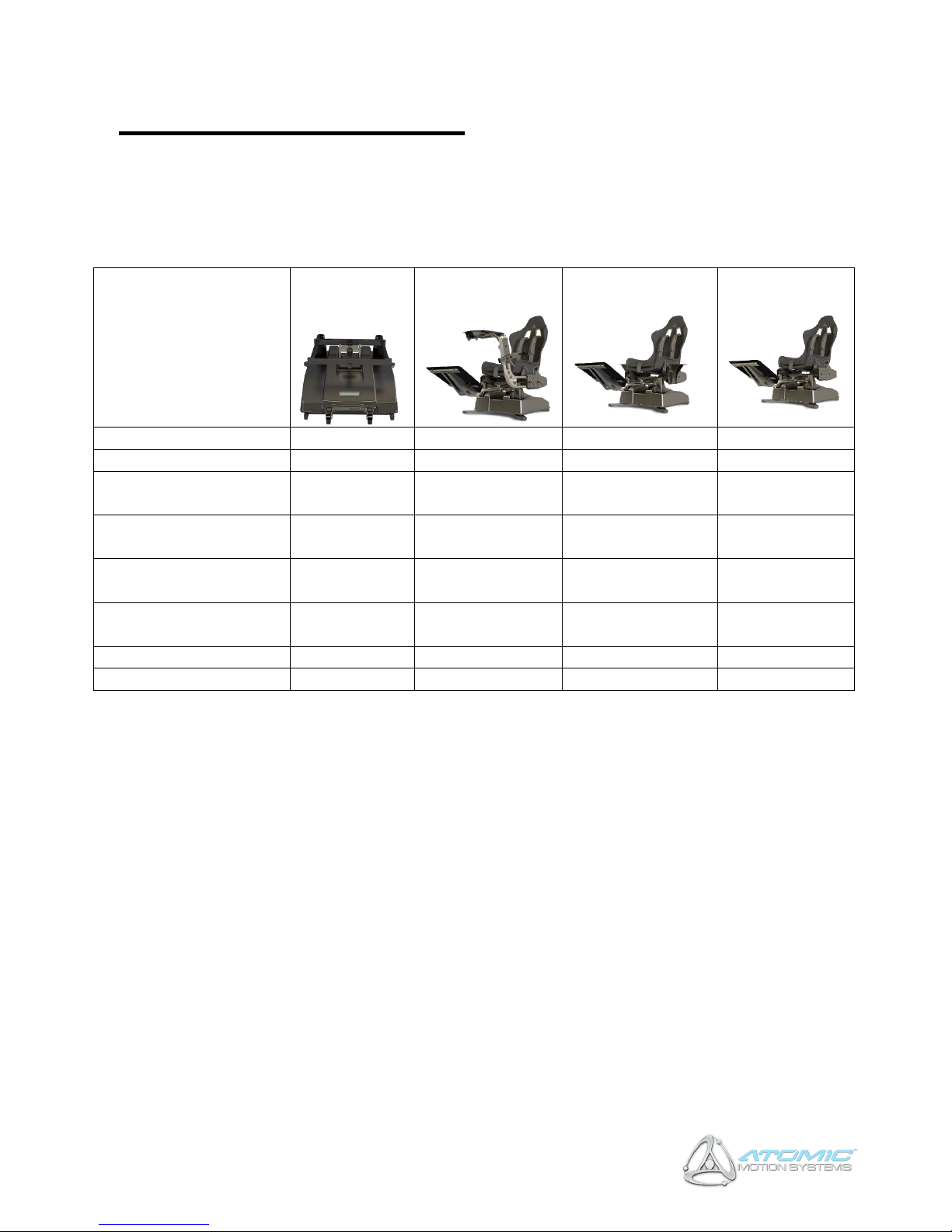
Most system components are factory pre-assembled. The table below shows the constituent components
by System type.
System
Motion Base
Racing / Flight
System
HOTAS System
Passenger
System
A3 Base Unit
Seat & seat fasteners
Foot rest / pedal mount
(2 parts)
Steering wheel / flight
yoke mount (2 parts)
Shifter / throttle / shift
panel mount & fasteners
Flight stick / throttle side
mount x 2
USB Cable
IEC Power Cable
2.2. Tools Required
• 17mm spanner / adjustable spanner
• Small flat-head screw driver, 3.5mm wide tip ideal, < 4mm (TTi units only)
2.2.1. Additional Recommended Tools
• 13mm spanner
• 6mm allen key
• 5mm allen key
• Cable Ties or Velcro Straps (for securing controller cables)
Page 6
6
A3 Motion Simulators, Assembly & Instruction Manual, November 2018
3 Motion Base Setup
3.1. Seat Installation & Adjustment
Remove the Atomic A3 base unit from its packaging and situate it on a level, stable operating surface
for intended use. WARNING: Never lift the base unit by the plastic housing, or damage may result to
the mounts (the housing is ‘floating’ for safety reasons). Always lift from the front and rear of
the metal top-table.
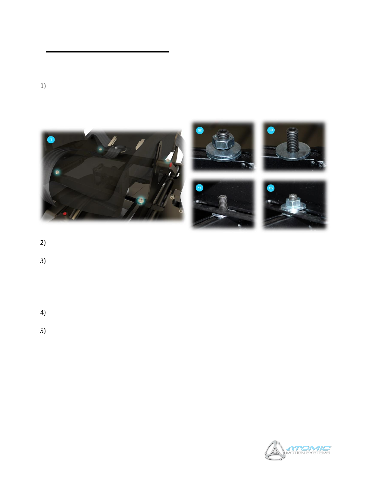
Locate the four mounting posts highlighted in the picture above (1). Each one has a nut attached with
two washers which must be located above and below the seat mount respectively.
(2) shows how each mounting post appears then the system is first unpacked, Remove the nut and
top washer from all four mounting posts, leaving the lower washer in-place on each (3). OPTIONAL:
The posts can be shifted laterally to support varying seat-widths if you are fitting your own seat. To do
this, the mounting post can be loosened by inserting an allen key into the top of each post and turning
anti-clockwise. Slide the posts to the position you require and re-tighten the posts by turning
the allen key clockwise.
Line up each of the seat rail slots with the mounting posts ensuring each rail is correctly seated on the
bottom washer (4).
Place the top washer onto each mounting post and screw down each of the four nuts on top of it
(5). Do not fully tighten the nuts yet – tighten just enough so the seat can still slide forward and
backwards along the rails. This is because the Centre of Gravity (COG) with need configuring once the
system is fully assembled.
Page 7
7
A3 Motion Simulators, Assembly & Instruction Manual, November 2018
3.2. Tactile Transducers
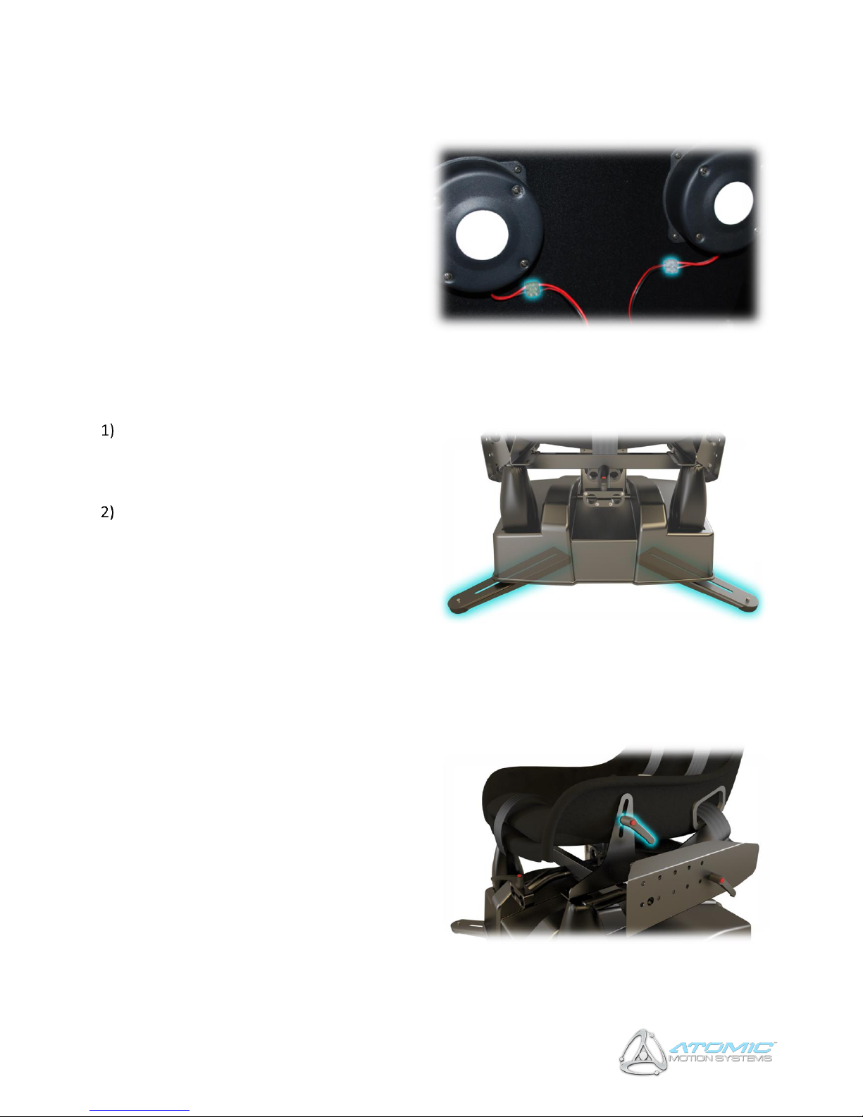
(TTi-equipped systems only) – Connect the
tactile transducers (attached to the bottom of
the seat) to the motion base using the
connectors shown below, ensuring red is
connected to red and black to black on each side.
3.3. Support Legs
Site the motion base on a level surface, and
extend the support legs highlighted in the
picture on the left. Ensure the plastic feet are
making contact with the ground.
For further stability, holes are provided on
the bottom of the base unit to allow it to be
secured to a platform if desired. Note: this
requires the removal of support legs and
castors, please contact AMS for further
information and advice.
3.4. Seat Adjustment
To adjust the seat inclination (reclination/tilt),
loosen the inclination levers shown on the right by
turning anticlockwise. Adjust the seat to the
desired inclination, then retighten the levers by
turning clockwise. If further tightening is required,
press and hold the red button on the lever
(disengaging it from the tightening mechanism),
turn anti-clockwise, release the button and further
tighten clockwise.
Page 8
8
A3 Motion Simulators, Assembly & Instruction Manual, November 2018
4 Foot Rest / Pedal Mount Installation &
Adjustment
4.1. Installation
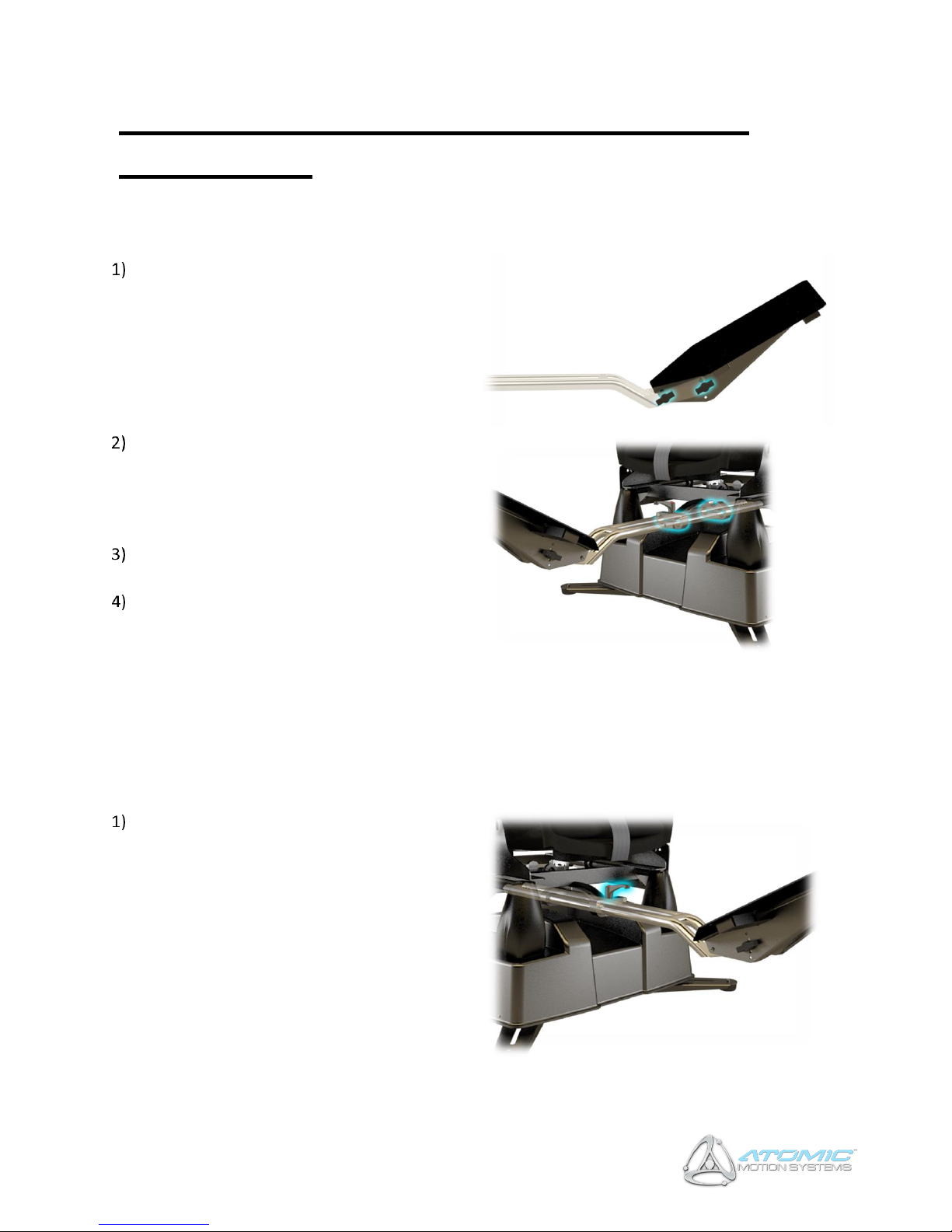
Attach the pedal mount plate to its mounting
post using the supplied thumb screws as
shown on the right (two on each side). To
adjust the angle of the mount see ‘Tilt
Adjustment’ below.
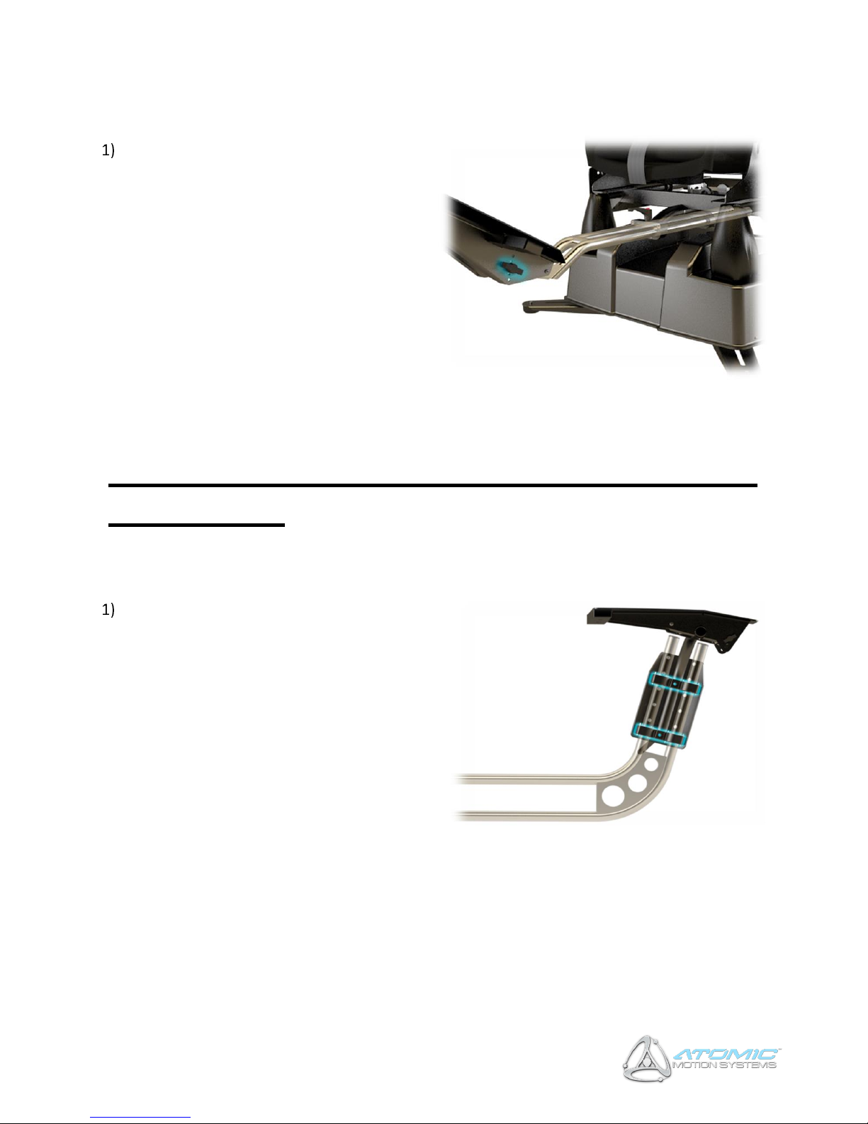
Insert the pedal mount into the base at the
points shown in the picture on the right.
Ensure the bars pass through both of the
clamps indicated, and secure as shown below
(Reach Adjustment).
Attach your pedal set to the foot-rest via the
mounting holes provided.
If your pedal set is incompatible with the foot
rest mounting holes, straps can be used
instead. However, AMS strongly recommend
additional holes are drille to provide
additional stability where possible.
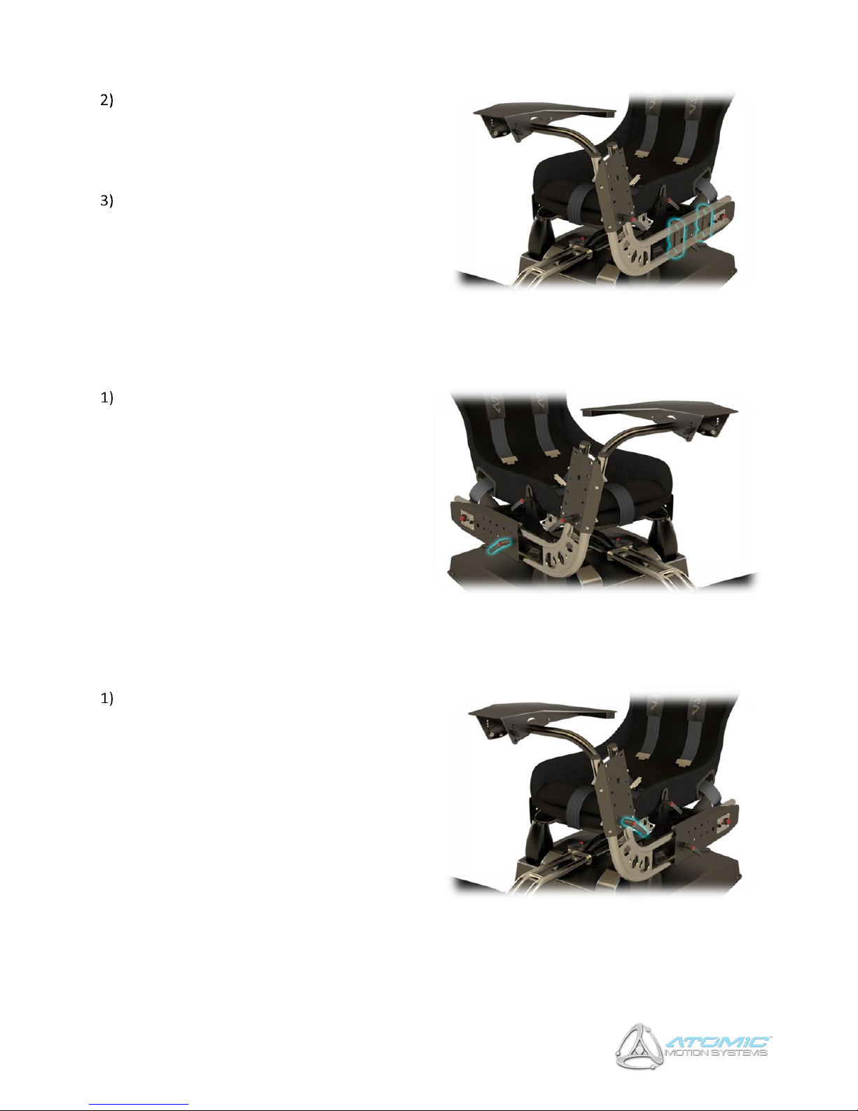
4.2. Reach Adjustment
Loosen the adjustment knob shown on the
left by turning anti-clockwise. Slide the foot
rest towards or away from the seat as
required (ensuring that it is always seated
within the clamps shown above) and secure in
place by tightening the adjustment knob
(clockwise).
Page 9
9
A3 Motion Simulators, Assembly & Instruction Manual, November 2018
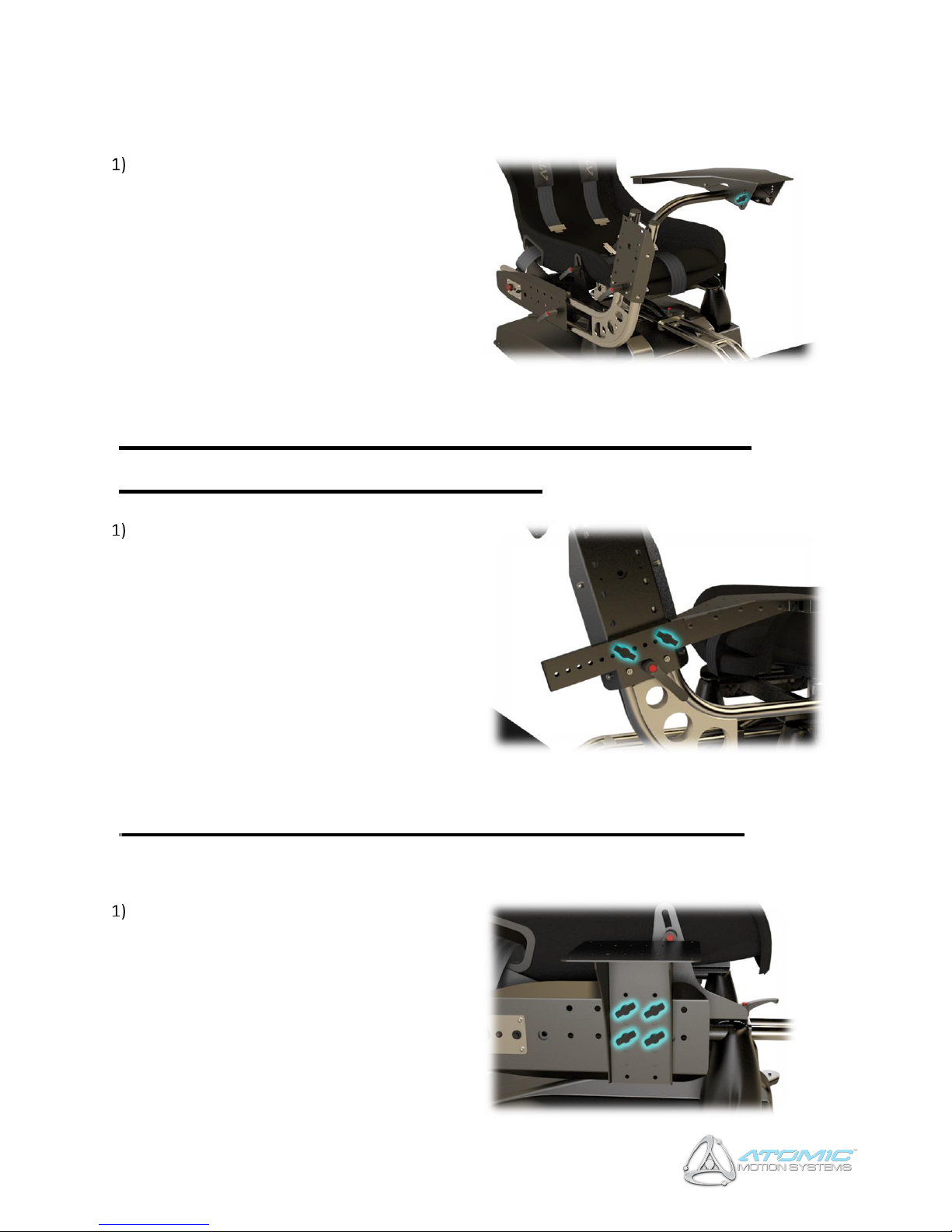
4.3. Tilt Adjustment
Remove the thumb screws shown in the
picture on the right (and located on the left
and right of the foot rest / pedal mount),
adjust tilt to desired position and replace
thumb screws.
5 Steering Wheel / Yoke Mount Installation &
Adjustment
5.1. Installation
Attach the wheel / yoke mount top assembly
to its bottom assembly as shown on the right,
and secure in place using the clamp shown
below (Height Adjustment section). Note: The
steering wheel / yoke mount mechanism is
reversible to facilitate both left and right hand
drive layouts – please contact AMS for further
instruction if required.
Page 10
10
A3 Motion Simulators, Assembly & Instruction Manual, November 2018
Insert the wheel / yoke into the base at the
points shown in the picture on the right.
Ensure the bars pass through both of the
clamps indicated, and secure as shown below
(Reach Adjustment).
Attach your steering wheel or flight yoke to
the steering wheel table via the clamp bar
and, if additional stability is required also the
holes provided.
5.2. Reach Adjustment
Loosen the adjustment knob shown on the
left by turning anti-clockwise. Slide the wheel
/ yoke mount assembly towards or away
from the seat as required (ensuring that it is
always seated within the clamps shown in the
picture above) and secure in place by
tightening the adjustment knob (clockwise).
5.3. Height Adjustment
Loosen the adjustment knob shown on the
right by turning anti-clockwise. Slide the
wheel / yoke mount top-assembly higher or
lower as required and secure in place by
tightening the adjustment knob (clockwise).
Page 11
11
A3 Motion Simulators, Assembly & Instruction Manual, November 2018
5.4. Tilt Adjustment
Remove the thumb screws shown on the left
(and located on the left and right of the wheel
/ yoke mount), adjust tilt to desired position
and replace thumb screws.
6 Shifter / Throttle / Switch Panel Mount
Installation & Adjustment
Remove the thumb screws shown in the
picture on the right. Adjust the height and
reach (relative to the wheel / yoke mount
assembly) using the indexing holes provided,
and replace / tighten the thumb screws.
7 Side Mount Installation & Adjustment
Remove the thumb screws shown in the
picture on the right. Adjust the height and
reach (relative to the motion base) using the
indexing holes provided, and replace / tighten
the thumb screws. NB The side mount can be
located on either the left or right of the
motion base.
Page 12
12
A3 Motion Simulators, Assembly & Instruction Manual, November 2018
8 Centre of Gravity (COG) Setup
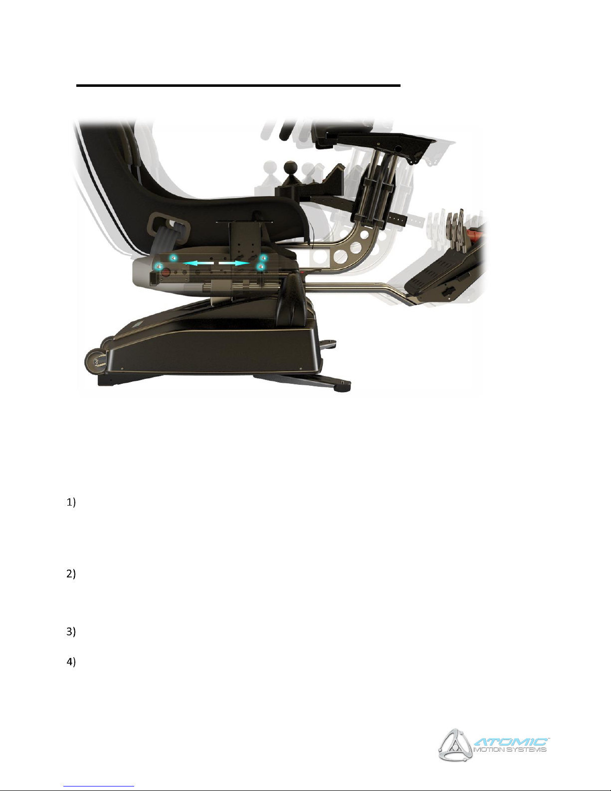
In order to maximise the performance of your system, it is important the COG is configured correctly based
on the controllers you wish to use (some pedal sets are significantly heavier than others for example). Prior
to configuring the COG, ensure you have fully assembled the unit, attached your controllers and adjusted
everything for comfort by following the previous instructions in this manual. NOTE: Significantly incorrect
COG settings can be detrimental to performance and reduce actuator life!
Ensure the power is ON (see the Operation section) and the actuators homed to their centre
positions. With your back against the back of the seat (in normal seated position), press and hold the
red emergency stop button for 4 seconds until power is disconnected from the actuators. If the upper
motion platform does not fall to the front or rear (side to side movement is ok), the COG is balanced –
proceed to step 4. If the COG is not balanced, proceed to step 2.
If the motion platform falls to either the front or the rear, loosen the reach adjustment levers of the
steering wheel and pedal mounts. Slide the seat forwards or backwards along its mounting rails (in
the opposite direction to which the platform was falling), moving the wheel and pedal mounts by the
same amount as the seat to maintain the driving position.
Re-power the actuators by pressing the black button (see the Operation section), and once homed
repeat the above process from step 1 until the correct balance is achieved.
When satisfied the COG is configured correctly, fully tighten the seat mounting nuts shown in the
picture above, along with the wheel and pedal mount reach adjustment levers.
Note: In situations where many users will be riding (e.g. commercial settings), it is recommended the COG
is configured for an average height user within the group to obtain the best results.
Page 13
13
A3 Motion Simulators, Assembly & Instruction Manual, November 2018
9 Wiring (Rear IO Panel)
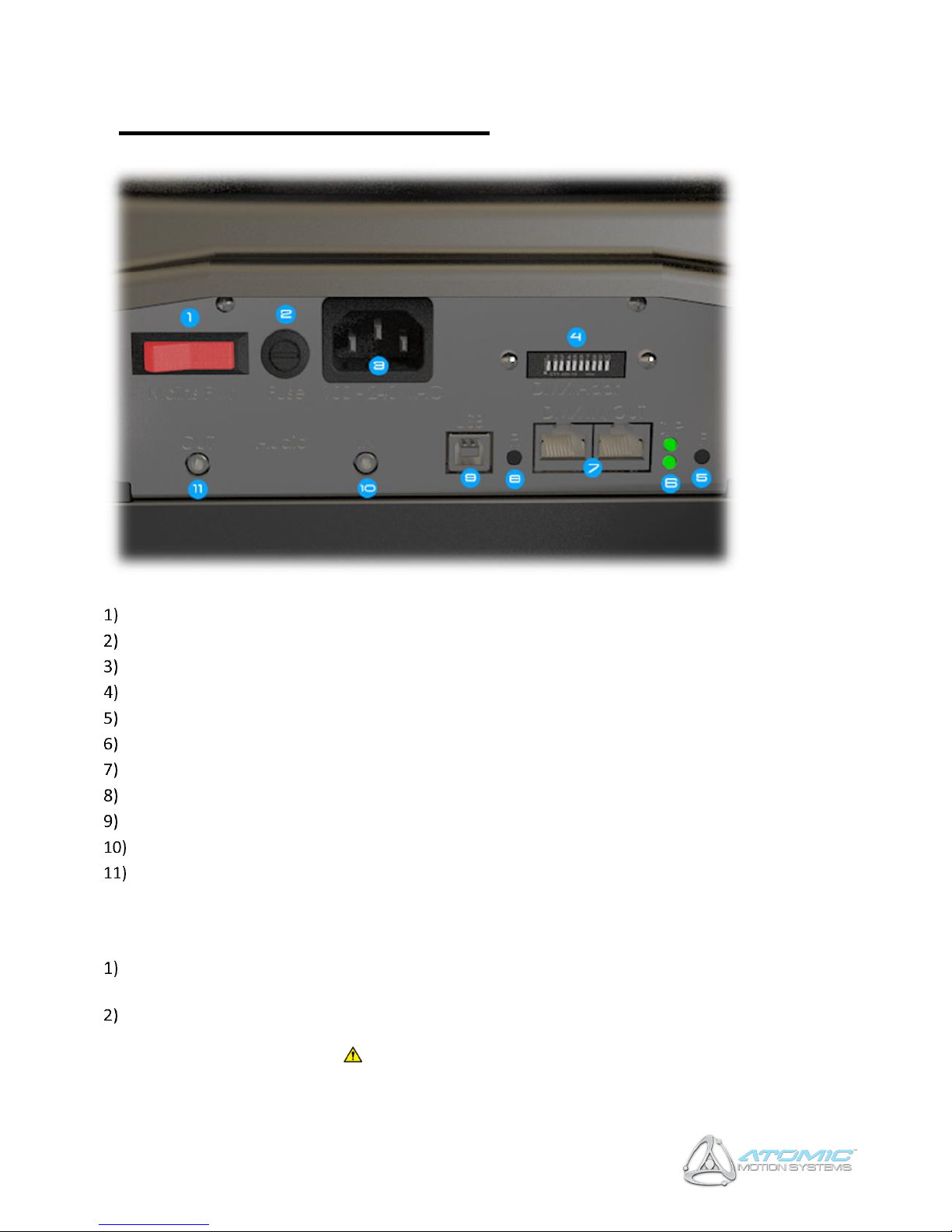
Mains power switch (illuminated when on)
Fuse holder
IEC (mains power) input
Motion base DMX address
‘F’ (Function) button
Indicator LEDS (top = controller status, bottom = power)
DMX networking IO ports
‘R’ (Reset) button
USB input
Audio input (TTi units only)
Audio output (TTi units only)
9.1. Basic Setup
Connect the supplied USB lead to the USB port ((9) USB Input), and the other end to any available
USB 1.1 (or above) port on your computer.
Connect the supplied IEC Mains lead to the Power port ((3) IEC Input), and the other end to any
available mains socket. The acceptable input voltage range is universally compatible with all standard
mains power supply systems ( 100-240VAC, 50/60Hz).
Page 14
14
A3 Motion Simulators, Assembly & Instruction Manual, November 2018
9.1.1. Amplifier Wiring (TTi Units Only)
If you have a TTi enabled unit, the following additional (unsupplied) cables are required:
• 1 x 3.5mm male > 3.5mm male jack cable.
• 1 x 3.5mm male > 2 x Phono (L/R) audio jack cable (optional).
Connect one end of the 3.5mm male > 3.5mm lead to the 'Speaker / Headphone Out' port on your PC
(please refer to your PC's instruction manual if you require more information), and the other to the
'Audio IN' port ((10) Audio Input).
Connect your headphones (active only, port is not sufficient for passive headphones) or PC speakers
to the 'Audio OUT' port ((11) Audio Input). Alternatively, if using a hi-fi amplifier connect the 3.5mm >
2 x Phono cable between the 'Audio OUT' port ((11) Audio Output) and any available line input on
your amplifier.
WARNING: Output levels of audio devices can vary and the amplifier supplied has a large adjustment range
to ensure lower level signals can be amplified to a useful level (although too low a signal will still produce a
weak tactile transducer response.) As a result it is possible to over amplify a strong input signal. Overamplification will cause damage to the TTi system and will be noticeable by audible knocks and clicks from
the transducers. If you hear these, turn the gain down until they disappear to avoid damage.
10 Operation
10.1. Power
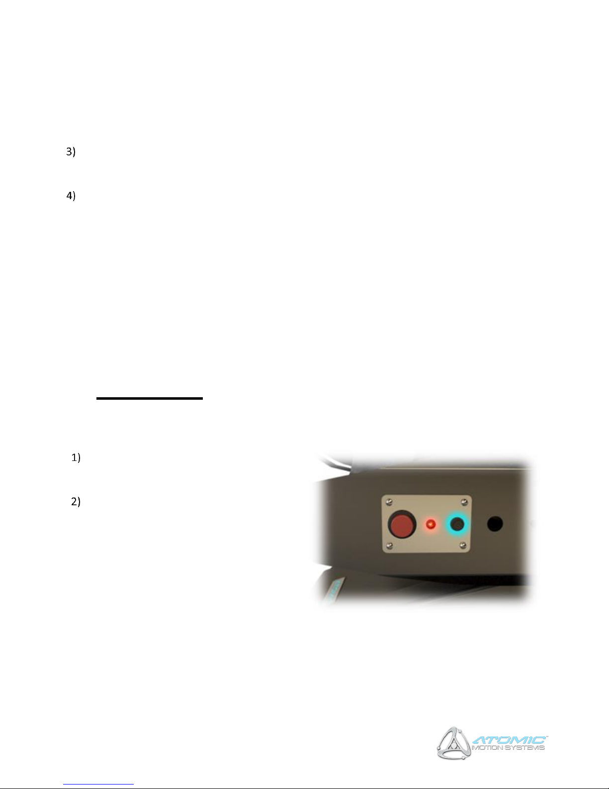
Once power is connected to the unit, ensure
the AC power switch is on ((1) Mains switch).
The AC switch will illuminate.
Ensuring the motion base is clear of any
hazards, press the small black
button depicted in the switch panel picture
right (Safety Interlock System). The ‘Atomic’
logo should light up blue and the unit home
to its centre-position, ready for operation. If
this does not happen, please read the Safety
Interlock System instructions below. You can
also refer to Appendix C - Troubleshooting.
Page 15
15
A3 Motion Simulators, Assembly & Instruction Manual, November 2018
10.2. Safety Interlock System
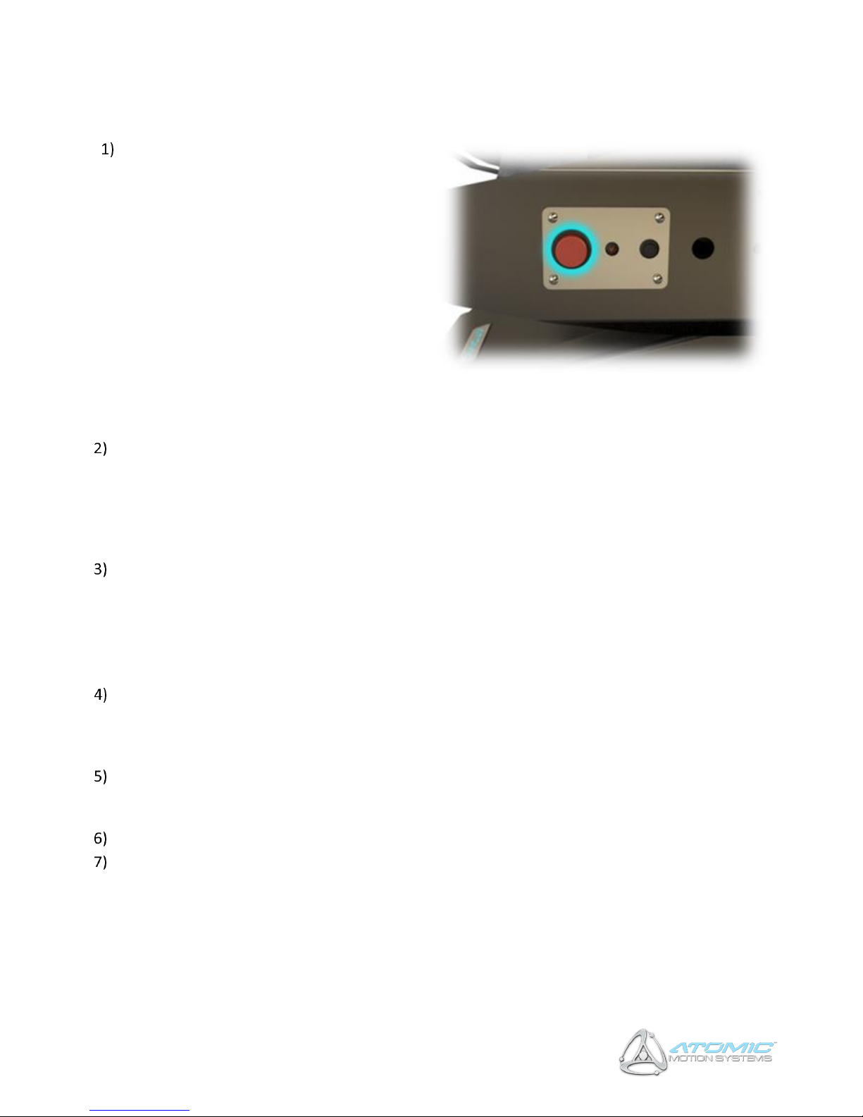
The unit has a number of safety features,
including a trap detection
mechanism and emergency stop button.
The trap detection mechanism consists of 4
switches, one at each corner of the base
(where the housing is attached) – in the event
a trapped foreign body is detected while
motion is active, this will push the housing
down and activate one or more of these
switches, stopping the motion and locking the
actuators in their place to prevent further
movement. The emergency stop button is the
big red button shown right, and when
pressed will also stop the actuators,
preventing further movement.
When either the trap detection mechanism or emergency stop button is activated, the system will go
into ‘safety interlock’, and this condition will be highlighted by the red LED next to the emergency
stop button (the ‘Atomic’ logo will also turn red). NOTE: pressing the emergency stop button quickly
will lock the actuators in their place, pressing and holding for longer than 4 seconds will disconnect
power to the actuators (and amplifier in a TTi-equipped unit) completely to allow safe removal of any
trapped object.
To exit the safety interlock mode and resume normal operation, press the black ON button shown in
section 11.1
10.3. Indicator LEDs
When USB power (but not mains power) is connected, the power LED on the rear IO panel will be
illuminated RED. When mains power (but not USB power) is connected, the power LED on the rear IO
panel will be illuminated GREEN. When both power sources are connected (required for use), the
power LED will be illuminated YELLOW and the unit is ON.
While in the ON state, pressing the black button will place the unit into the IDLING (awaiting data)
state - it will home to its centre-position and the status LED on the rear IO panel will blink slowly. The
Atomic logo will be lit up blue.
When the unit is ACTIVE (receiving motion data), the status LED will blink rapidly.
When the unit is in SAFETY INTERLOCK MODE, the red LED next to the emergency stop button will be
illuminated, and the ‘Atomic’ logo lit up red.
Page 16
16
A3 Motion Simulators, Assembly & Instruction Manual, November 2018
11 Driver Software Installation
The Atomic can be controlled using either a PC (via Actuate Motion software or similar), or DMX capable
controller (refer to Appendix B – DMX Network Setup).
11.1. Actuate Motion
A license to the Actuate Motion software is granted with your simulator. If you have not already received
your license and download instructions, contact [email protected]
https://actuate-motion.com/
12 Safety Precautions
Ensure power to the unit is switched off when not in use.
While not essential, it is recommended a harness is worn at all times for added safety.
Ensure spectators are kept at arms length when the unit is in operation, and there are no obstructions
in or around the base or foot rest.
Ensure loose clothing is not in the proximity of any moving parts to reduce the risk of trapping or
injury.
For maximum stability, the base should be mounted on a flat, level surface, with the front support
legs extended and all support feet making good contact with the ground when a user is seated. The
rear castors should be just above, or barely touching the ground.
As with any other highly-dynamic system, it is good practice to check all adjustment levers / fasteners
are tight and secure before each use. The Atomic is a highly-durable system, however it is necessary
to provide some user-releasable mechanisms to facilitate rapid comfort adjustment. It may be
preferable in heavy-use situations (e.g. commercial scenarios) to replace hand-adjustable levers and
fasteners will tooled alternatives.
Ensure users keep their feet on the foot rest / pedal mount at all times while the unit is active to
prevent trapping or injury.
Adjust the system for comfort prior to operation, ensuring the user’s limbs can move freely and easily.
It is strongly recommended the safety interlock mechanism is activated (via the emergency stop
button) when entering or exiting the seat, to reduce the risk of injury in case unexpected motion
occurs.
When in use, it is strongly recommended pitch/roll movement range settings do not allow the
actuators to hit their end-stops (indicated by a knocking sound when the pitch or roll reaches the end
of its travel). Under normal use there is a protection mechanism to prevent this, however if abnormal
Page 17

17
A3 Motion Simulators, Assembly & Instruction Manual, November 2018
loads are applied there is a slim possibility this can be defeated, potentially damaging the actuators
due to excessive shock. If you feel this is happening, reduce your pitch/roll movement range settings.
Take care when entering and exiting the seat, sudden impacts can result in excessive load / shock to
the actuators. The actuators feature an overload protection mechanism which quickly disconnects
power to the relevant actuator in these circumstances – should this happen, you will need to reset
the unit by disconnecting and reconnecting both power and the USB cable.
13 Hints & Tips
Adjust your system fully to find the perfect driving position before starting. The Atomic provides
extensive adjustment to simulate many different types of vehicle layout, which can greatly enhance
the feel of the system when configured properly.
Ensure the COG is configured correctly for the control set and user to maximise performance. If many
users are to be using the system (e.g. in commercial situations), configure the COG for an average
height person for optimum results.
Use of a harness does not only provide added safety, but when tightly secured can significantly
enhance the motion sensation. This is particularly applicable to highly-dynamic applications such as
racing or rallying, where road surface detail typically produces smaller movements, some of which
may not be perceived due to the natural shock-absorption of the upper-body with respect to the seat.
The Atomic can provide exceptionally fast motion response and use of the harness maximises this
benefit.
Experiment extensively with your software settings! to fine-tune your ride, in particular force level
and pitch/roll movement range. As with any other system, incorrect settings may yield disappointing
motion results, but a correctly tuned system can produce an incredible experience. Sometimes less is
more – excessive force settings can result in ‘overshoot’ (producing a jittery feeling in flight-type
applications), and excessive pitch/roll movement range settings can reduce the response of the
system to more subtle feedback such as road surface detail.
If you have a TTi unit, ensure your line level input (connected to the Audio IN port on the Atomic) has
a strong signal and the volume output on your computer is set to maximum for the best results.
If possible, secure your controllers firmly to their mounts using the mounting holes provided.
To enhance the feeling of forward acceleration, it is more advisable to tilt the seat inclination /
reclination further backwards using the mechanism described in the Seat Adjustment section, rather
than offsetting the centre position of the unit in your software. This allows the system to still be able
to respond to the greatest range of pitch motion possible for both acceleration and braking. If you are
unsure, it is recommended you set the seat inclination / reclination to about halfway for most
applications.
If you are using force-feedback controllers, use a high force setting – the Atomic gives a substantial
amount of force-feedback, so if your usual controller force settings are low they may get a little lost in
the experience.
For additional immersion and a better perceived motion experience it is highly recommended either
headphones or a loud audio system is used.
For increased immersion still, use a large 3D ready screen, projector, multi-screen surround or Virtual
Reality HMD setup. If possible, remember to switch off the lights!
Page 18

18
A3 Motion Simulators, Assembly & Instruction Manual, November 2018
14 Appendix A - Device Firmware Update
(DFU)
From time to time it may be necessary to update the firmware of your Atomic system as AMS introduce
additional functionality. This is done via the AMS DFU (Device Firmware Updater), which is a software
utility available freely from AMS for your Windows-compatible PC.
To update your device’s firmware:
Ensure the AMS DFU is correctly installed on your PC (this also installs the required drivers to update
your firmware).
Put the Atomic in ‘DFU’ mode:- Using a pair of pointed implements (e.g. Ballpoint pen), press and
hold the ‘F’ (function) button on the Atomic’s I/O panel.
Keeping the ‘F’ (function) button held down, press and release the ‘R’ (reset) button on the Atomic’s
I/O panel.
Finally, release the ‘F’ (function) button. The device is now in DFU mode.
Follow the on-screen instructions provided with the AMS DFU to perform the firmware update, and
once complete disconnect and reconnect both the power and USB leads to the Atomic.
15 Appendix B - DMX Network Setup
(Optional)
If you have a multiple units or devices you wish to link together to operate in unison, this is achieved via
the DMX networking capability. Devices can be controlled using either your PC or a DMX compatible
control desk (see the DMX Channel Assignments section).
Additional cables required (unsupplied):-
• 1 or more standard RJ-45 PC network cables.
• (Optional, control desk only) 1 x 3 or 5 pin XLR (depending on DMX control desk) > RJ-45 DMX cable.
15.1. PC Controlled
Connect the first motion system in the chain to your PC using the supplied USB cable as described
previously.
Connect one end of the RJ-45 cable to the DMX Out port ((7) DMX ports) on the first motion system in
the chain to the DMX In port on the second motion system.
For each subsequent system you wish to control simultaneously, connect another RJ-45 cable from
the DMX Out port of the previous unit to the DMX In port of the next.
Page 19

19
A3 Motion Simulators, Assembly & Instruction Manual, November 2018
15.2. DMX Desk Controlled
Connect the DMX In port ((7) DMX ports) of the first motion system in the chain to your DMX control
desk using the XLR > RJ-45 DMX cable.
Chain subsequent units together by following the second and third steps outlined in the ‘PC
Controlled’ section above.
15.2.1. Dip Switch Settings
The DMX512 address of the unit is set using switches 1-9 on the ADDR/TERM switch panel ((4) DMX
address). As with most DMX-compatible equipment, the addresses are set using a binary system,
by summating the values of all enabled (on) switches (1-9) to give the address. e.g. switch 1 enabled
(on) and 2-9 disabled (off) = Channel 1, switches 2 and 4 enabled (and all others disabled) =
Channel 10, and so on. Units set with the same address in the chain will operate in unison.
IMPORTANT: Switch 10 should only be enabled (on) in the LAST unit in the DMX chain - this
enables the termination resistor, and if left disabled (off) unexpected results may occur. If it is
enabled on a unit prior to the last in the chain, the subsequent units may not function correctly.
If you are unsure about DMX channel setup or will only be using a single motion system via PC
control, just set the unit to channel 1 by enabling switch 1 (on) and disabling all others (off).
Page 20
20
A3 Motion Simulators, Assembly & Instruction Manual, November 2018
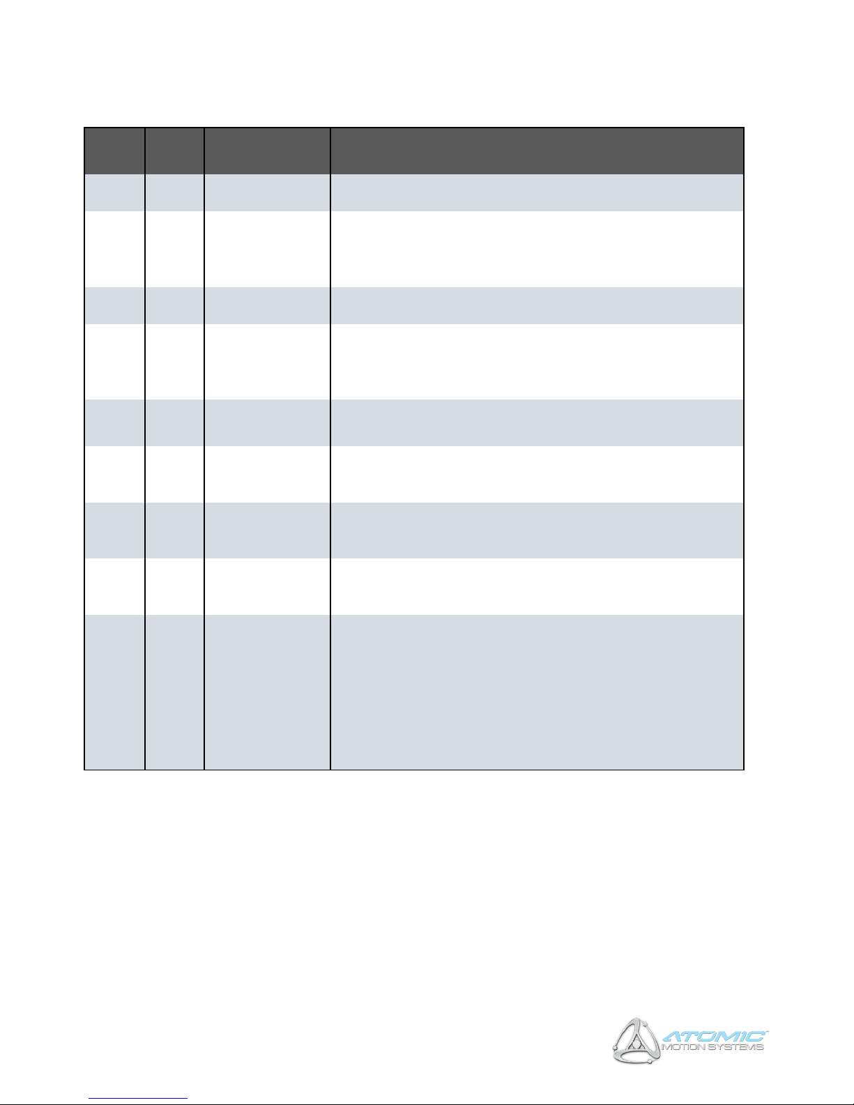
15.2.2. DMX Channel Assignments
Channel
Range
Title
Description
1
0 -255
Pitch (Coarse)
Coarse pitch position (0 = fully backward, 255 = fully forward)
2
0 -255
Pitch (Fine)
Fine pitch position. Used in conjunction with Pitch (Coarse) to form a
16-bit number, allowing 65536 possible positions. Pitch (Coarse) is
the high-order byte
3
0 -255
Roll (Coarse)
Coarse roll position (0 = fully left, 255 = fully right)
4
0 -255
Roll (Fine)
Fine roll position. Used in conjunction with Roll (Coarse) to form a
16-bit number, allowing 65536 possible positions. Roll (Coarse) is the
high-order byte
5
0 -255
Force
Movement force (0 = lowest, 255 = highest)
6
0-255
Max Speed
Movement maximum speed (0 = lowest, 255 = highest). If unsure,
set this to be permanently 255
7
0-255
TT Gain (TTi Units
only)
Sets the gain (volume) of the tactile transducers (0 = lowest, 255 =
highest)
8
0-255
TT LFC (TTi Units
only)
Sets the LFC (Low Frequency Cut-off) of the tactile transducers (0 =
lowest (20hz), 255 = highest (100hz))
9
0-255
Command
Used to issue one-shot commands to the unit. Must be set to 0 at
all other times. Commands are as follows:-
• 255 – Reset system
It is recommended the command channel is set to the desired value
for a minimum of 0.5 seconds before being reverted back to zero, to
ensure the command is transmitted correctly
Page 21
21
A3 Motion Simulators, Assembly & Instruction Manual, November 2018
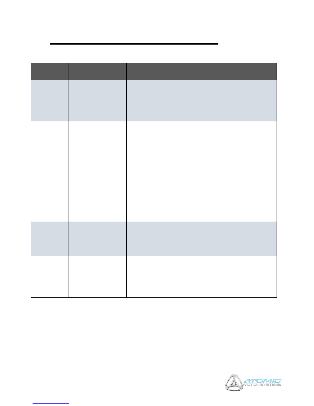
16 Appendix C – Troubleshooting
Probem
Possible Cause(s)
Possible Solution(s)
No motion, one
or more
actuators move
freely
• Power
disconnected
• Actuator overload
safety mechanism
defeated
• Check power is connected and AC power light is illuminated.
• If power is connected, disconnect power and USB, then
reconnect.
• Press the black ON button (marked ‘1’)
No motion,
actuators
locked in place
• Safety interlock
activated (LED on
switch panel and
‘Atomic’ logo will
be illuminated red).
• Incorrect software
settings.
• Incorrect DMX
channel setting.
• Disengage the safety interlock by pressing the black ON button
(marked ‘1’).
• If the red LED / ‘Atomic’ logo remains illuminated, check the
base plastic cover is free from obstruction and not pressing
down on any of the 4 safety switches.
• Ensure USB cable is correctly connected and system is present
in Windows Device Manager (refer to Windows manual).
• Check software settings to ensure system is enabled and force
or pitch/roll movement range settings are not 0 (refer to
software user manual).
• Check game has been recognised in software and motion
preview is showing movement.
• Check DMX channel is set correctly and corresponds with that
in software (refer to software user manual)
Poor motion
output
• Incorrect software
settings
• Incorrect COG
configuration
• Increase pitch / roll movement range and / or force setting in
software (refer to software user manual)
• Correctly configure the COG
No or poor
Tactile
Transducer
feedback (TTi
units only)
• Audio cables not
correctly
connected.
• PC sound output
low or muted.
• Ensure audio cables are properly connected, PC sound output
is set to full and audio cable is connected to correct port on
soundcard.
• Check TT Gain software settings (refer to software user
manual)
 Loading...