

Page 1
TILLER/MULCHER Electric Model 710
MULTI INTERNATIONAL GOLD MEDALS &
AWARD WINNING LAWN EDGERS & TILLERS
! NOTE
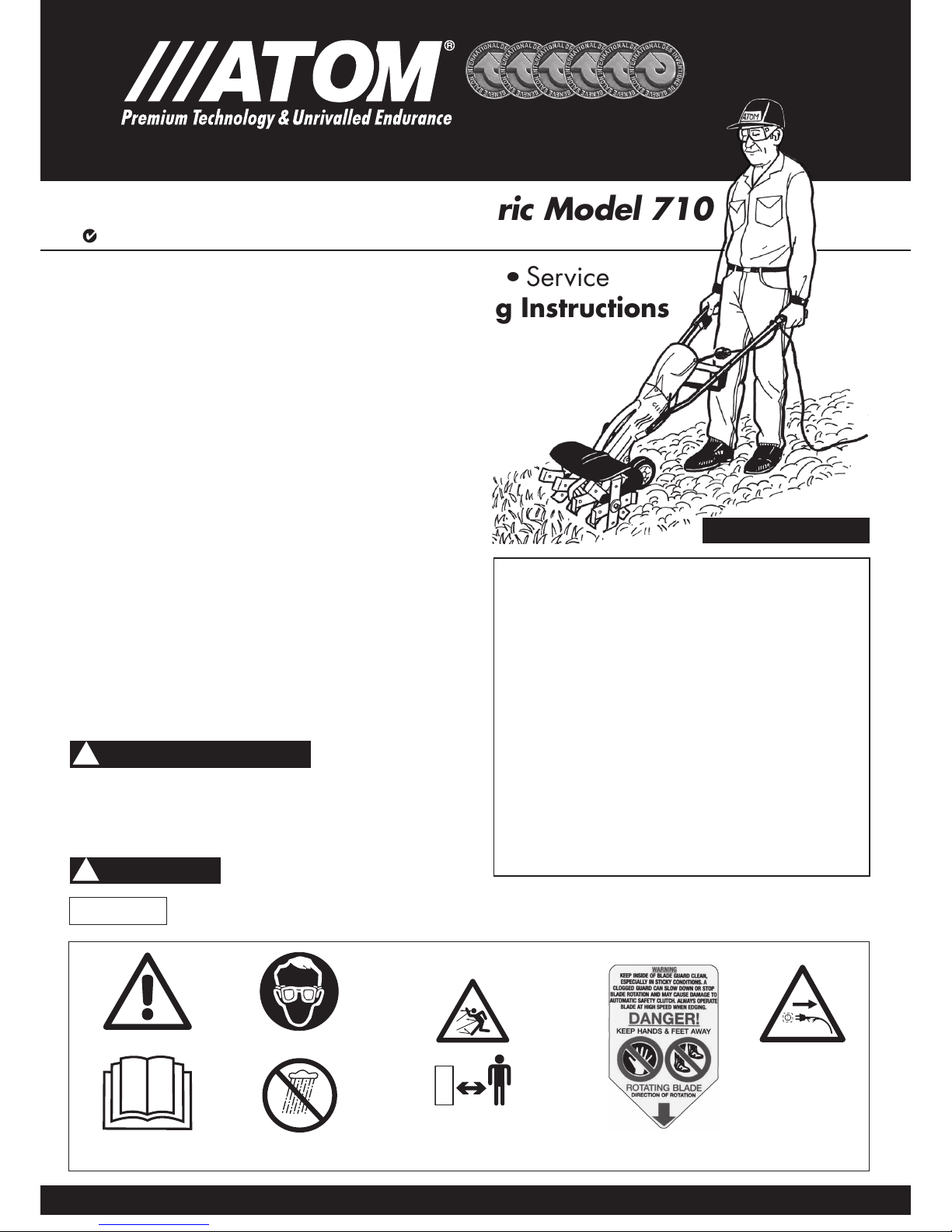
Read operators manual
Do not expose motor
to moisture
Wear eye protection
Keep bystanders away
15m (50 feet)
Blade cover label
SAFETY WARNING LABELS
ATOM Tillers have Australian and foreign Patents, Patent Pending, and Design Registrations.
FIG 2
Disconnect the
mains plug if the
cord is damaged or
entangled
ELECTRIC
PRODUCTS
ONL Y
ACN 000 583 924
160910
•
Safety Precautions
•
Assembling
•
Service
•
Operating and Tilling/Mulching Instructions
Important Manual – Do Not Throw Away
Manual always to be available for reference or
instructing new operators.
Introduction: Electric Tiller
This Atom Electric Tiller is designed to the highest standards
to ensure you many hours of uninterrupted service. Pay
special attention to the safety precautions. Only persons
who understand this Manual are to operate the Tiller.
To receive maximum performance and satisfaction from
your Tiller, it is important that you read and understand the
maintenance and safety precautions before using the unit.
Contact your Atom dealer or the Atom distributor in your
area if you do not understand or cannot carry out any of the
operating instructions in this Manual.
Atom’s philosophy is to continually improve all of its products.
As a result, engineering changes and improvements are made
from time to time. Appearances may differ between models.
This manual covers information required to operate, maintain
and service this electric Tiller.
AS WITH ANY POWER TOOL IMPROPER USE CAN CAUSE
SERIOUS INJURY. Make sure this manual is read and carefully
understood before starting or operating this equipment.
The purpose of Safety
Warnings and Notes in
this Manual is to attract your attention to possible dangers and
deserve your careful attention and understanding. The Safety
Warnings in this Manual and on the Tiller do not, by themselves,
eliminate any danger. The instructions or warnings they give are
not substitutes for proper accident prevention measures.
Failure to obey a safety warning can
result in injury to yourself and others.
Advises you of information or instructions vital
to the operation or maintenance of the equipment.
! SAFETY WARNING
! WARNING
MADE IN AUSTRALIA
FIG 1
Contents
Safety Warning Labels ....................................... 1
Safety Precautions ........................................ 2 - 3
Assembling the Tiller ...........................................3
Parts and Controls ............................................. 4
Starting and Stopping Instructions ....................... 4
Tilling & Mulching Instructions ........................ 4 - 5
Switch Adjustment ............................................. 6
Lubrication of Gears .......................................... 6
Warranty ......................................................... 6
Tine Installation & Removal ................................. 7
Parts List and Parts Illustration .......................... 7-8
The information contained in this manual is also
available at www.atomindustries.com
PAGE
Operator /
Owner Manual
63902MA-12
1711
Page 2
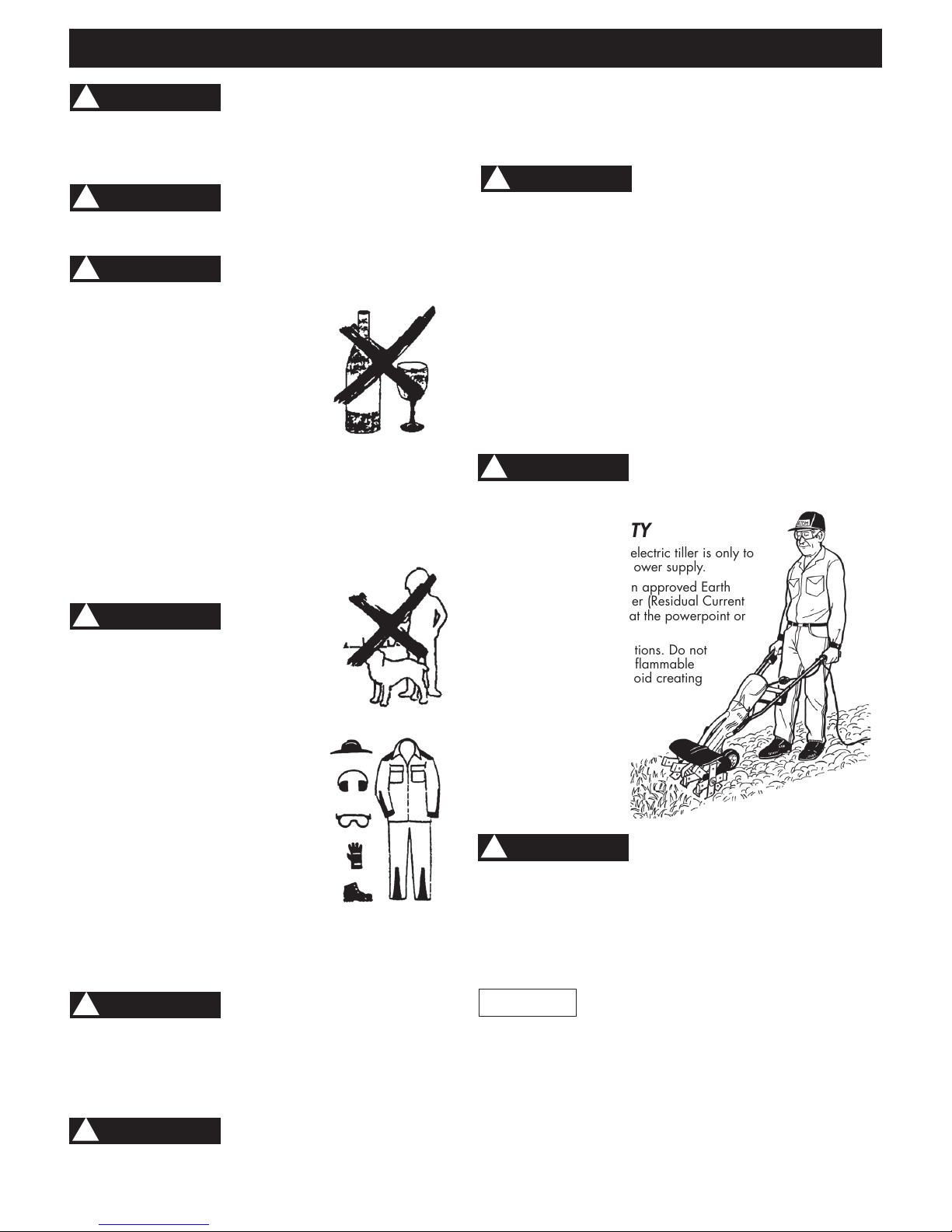
FIG 4
Proper eye protection is a
must. The blade cover may not
protect the operator from all moving foreign objects, even
though the discharge is directed away from the operator, as
ricochets and bouncebacks may occur during tiller operations.
Never operate an Atom Tiller unless wearing goggles or
properly fitting safety glasses with adequate front and side
protection which comply with ANSI Z 87.1.
Safe use of an Atom Tiller involves:
1.The Operator.
2.The Atom Tiller.
3.The use of the Atom Tiller.
THE OPERATOR
PHYSICAL CONDITION
Operator must be in good physical
condition and mental health, and not under the influence of
any substance (drugs, alcohol, etc.) which might impair vision,
dexterity or judgement (Fig 3).
Do not operate the Tiller when fatigued. Be alert – if you get tired
while operating the machine, take a break. Tiredness may result
in loss of control. Working with any power tool can be strenuous.
If you have any condition that might be aggravated
by strenuous work, check with your doctor
before operating the machine
FIG 3
PROPER CLOTHING
Clothing must be sturdy and snug-fitting,
but allow complete freedom of movement
(See Fig 5). Avoid loose-fitting jackets,
flared or cuffed pants, or anything that
could trip the operator. Wear overalls or
long pants to protect your legs. DO NOT
wear shorts. Use of gloves when working
with the Lawn Tiller is recommended.
Good footing is most important. Wear
sturdy shoes with nonslip soles. DO NOT
wear sandals, open footwear (flip-flops)
or operate with bare feet. In hot or sunny conditions, always
wear a hat and long sleeve shirt for protection against skin
cancers. Use of a good brand of sunscreen cream is also
recommended on exposed skin surfaces.
FIG 5
Replace immediately any worn or broken
debris deflector shield or blade cover.
Check from time to time that all screws are tight. Never operate
your machine if it is damaged, improperly adjusted or not
completely and securely assembled.
SAFE MAINTENENCE, REPAIR & STORING
Use only original Atom replacement parts for maintenance and
repair. Use of parts manufactured by others will void warranty
and/or may cause serious or fatal injury.
Always stop the motor, make sure
that the tines have stopped, before
adjusting tine height. Before doing any adjustment, maintenance
or repair work, or cleaning the unit or tines, disconnect extension
cord.
Follow the maintenance instructions in the appropriate section of
this manual. Any motor repairs should be carried out by a person
with suitable sevicing experience.
SAFE STARTING & WORKING CONDITIONS
Always inspect that the unit is in good working order before use.
When working with the Atom Tiller, always wrap your fingers
tightly around each handle grip. Keep your hands in this position
to have your machine under control at all times. NEVER attempt
to operate the Atom Tiller with one hand, as a loss of control may
result in serious or fatal injury. Make sure the handle grips are
in good condition and free of moisture, oil or grease. Use both
hands, one on each handle, to operate and control the tiller.
Do not overreach. Keep proper footing and balance at all times.
PAGE 2
SAFETY PRECAUTIONS
As with any power tool, the use of the
tiller with rotating blades may be
dangerous. It is important that you read, fully understand, and
observe the following safety precautions and warnings. Re-read
this operator’s manual and the safety instructions periodically.
Read and understand all labels attached to tiller.
! WARNING
Do not lend, rent or sell this machine
without the operator’s manual. Be sure
that anyone using this unit understands the information contained
in this manual before use.
! WARNING
! WARNING
This Tiller must
not be operated
by minors. Bystanders, especially children
and animals should not be allowed in the
area where a machine is in use and be at
least 15 metres (50 feet) away (Fig 4). If
approached switch off motor immediately.
When not in use store the tiller out
of reach of children.
! WARNING
! WARNING
! WARNING
As with any power tool, some special
safety precautions must be observed to
reduce the risk of personal injury. Careless or improper use may
cause serious or even fatal injury.
! WARNING
Tiller tines can cut extension cord. Keep
the extension cord away from
the cutting tines (Fig 6). A cut extension cord is
dangerous and can be fatal to you or others.
! WARNING
ELECTRICAL SAFETY
1. This double insulated electric tiller is only to
be used on 240 volt power supply.
2. Where possible use an approved Earth
Leakage Circuit Breaker (Residual Current
Device) safety switch at the powerpoint or
switchboard.
3. Avoid dangerous situations. Do not
use in the presence of flammable
liquids or gasses to avoid creating
a fire or explosion.
4. Do not attempt to use
unit if there is any
damage. Do
not use until
damage is
repaired by
an authorised
service centre.
Do not use in rain, in damp or wet
locations, or around swimming pools,
hot tubs etc. Do not expose to water, rain, or snow to avoid the
possibility of electrical shock.
5. Damaged supply cord (on Tiller motor). This must be replaced by
an authorised service agent or similarly qualified person in order
to avoid a hazzard.
6. Never carry the unit by the extension cord or yank the extension
cord to disconnect the unit.
! WARNING
! NOTE
Use extension cords specifically marked as
suitable for outdoor appliances. These have
minimum 1mm diameter copper wire. In Australia/NZ, these are
now yellow in colour. Do not use white coloured or light gauge
undersized extension cords as these will cause a drop in line
voltage resulting in loss of power and overheating. If in doubt,
use the next heavier guage.
Inspect the extension cord before each use and
do not use if damaged in any way.
FIG 6
Page 3
PAGE 3
SAFETY PRECAUTIONS
(
CONTINUED
)
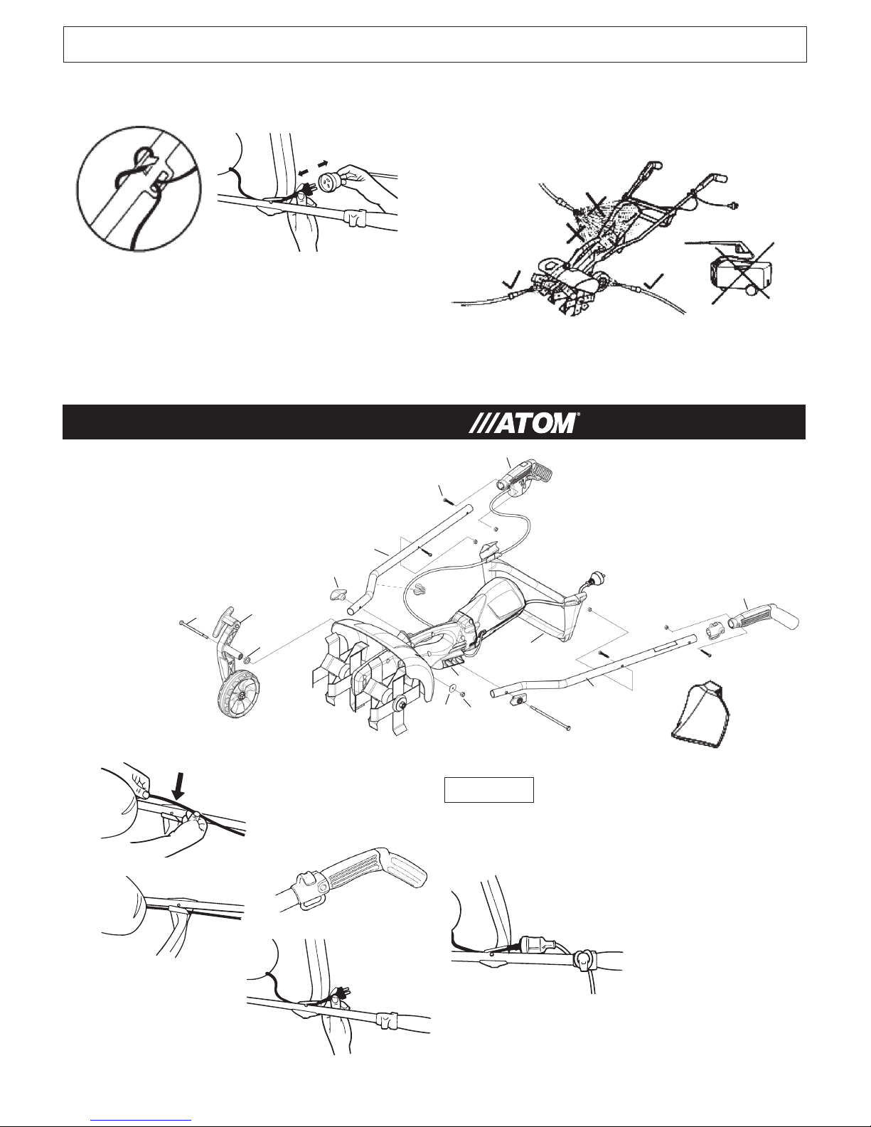
ASSEMBLING THE TILLER
Keep the extension cord clear of operator and obstacles at all times.
Do not expose the cords to heat, oil, water, or sharp edges.
Do not edge next to cord, or walk on or drive over cord.
Do not store unit outside but only indoors in secure dry place.
To reduce the possibility of the extension cord disconnecting
from the unit during operation, loop the extension cord to the
extension cord anchor as shown (Fig 8)
FIG 8
CLEANING UNIT AFTER USE
When cleaning, disconnect electrical cable (Fig 9) and do not use
water hose. Scrape dirt away. If motor accidentally wet by water,
allow to dry in the sun, inspect and ensure it is dry before use.
DO NOT USE hose water to clean machine as it could force
water into casing and motor.
Always disconnect motor power cable from extension cord
when removing tine cover, cleaning tines, adjusting wheel
depth, cleaning unit, etc.
Do not use the tiller if the switch does not turn the tiller on
and off properly. Repairs to the switch must be made by
qualified electrical service personnel.
Throttle cable #10 from motor must loop
under edger body and clip into place on
handle clip #17 then over top of cross brace #7 and clip into
place on RH top side of brace.
Attach extension cord to plug of motor and fit extension
cord to anchor (Fig 11E).
! NOTE
FIG 11A
FIG 11B
FIG 11C
FIG 11E
FIG 11D
FIG 9
TOP
VIEW
FIG 10
Slide O Ring #14 over wheel
arm #5 axle. Slide into Tiller
body. Slide Bolt #10 through
wheel arm, fitting washer #16
and screwing nylon nut #17
up tightly.
Fit cross brace #7 with base down as illustrated, to handle tubes
#3 & 5. Use 2 screws #8 and lock nuts #9 provided in
packet. Use straight blade screwdriver or torx 25
screwdriver. Screw on firmly.
Insert 175mm (6.5”) bolt #1 through the head
retainer #2 (note arrow points forward) then
through LH handle tube #3 then through edger
body #4 and RH handle tube #5.Handle tubes
are identical. Fit so label sits upwards.
Screw large wing nut #6 on
protruding bolt and
tighten.
Insert Trigger
Handle #11 onto
RH handle tube.
Use one screw #8
and one nut #9 to
fix handle to tube.
Clip throttle cable #10
into place, Fig 11A and
11B also through clip for handle #17.
FIG 11
1
8
4
12
17
5
7
9
9
8
11
2
10
9
13
Clip cord anchor #12 onto LH handle #13
and fit together onto LH handle tube #3
(Fig 11C). Fit screw #8 with nut #9. Clip
power plug cord of motor into place on LH
topside of cross brace #7 (Fig 11D).
16
15
14
8
6
17
16
3
FURROW
PLOW
ATTACHES TO
WHEEL ARM
Page 4

PARTS & CONTROLS
1+2.The handles of the Tiller are held by both hands.
3. The throttle interlock which releases the throttle trigger which switches on
motor for automatic safety clutch to engage and thus rotate tines.
4. Handle nut for holding handle tubes onto housing.
5. Depth adjustment for adjusting wheel to regulate tine depth.
6. Tine cover reduces the risk of flying debris
and direct contact with the feet or hands.
7. Handle to lift Tiller.
8. Tines rotate when motor is switched on.
9. Tine holding nuts RH (shown) & LH thread on each
end of tine shaft.
10. Wheel for moving and guiding tiller.
11. Cross Brace, attaches downward on
handle.
12. Left and right Handle Tubes.
13. Warning label.
14. Lift knob and twist to remove cover.
15. Cable clamp.
16. Electric motor assembly.
STARTING & STOPPING INSTRUCTIONS
PAGE 4
FIG 13
Switch motor on (Fig 13)
by pushing down safety
interlock with thumb
and pulling on
trigger. To
stop, release
trigger.
1
2
3
15
12
FIG 12
15
4
7
5
14
13
6
11
10
9
8
16
COMBINATION CULTIVATING, TILLING, ROTARY HOEING
1. The Atom Tiller is very easy and simple to use. It only takes a
few minutes to become an efficient user.
2. Thoroughly inspect the area where the tiller is to be used and
remove all long grass, stones, sticks, wires and other foreign
objects.
3. Adjust tine depth (Fig. 15A or 15B). Try the third hole closest
to operator.
4. Start motor and, with both arms fully extended downwards,
(Fig. 15C), hold both handle grips firmly.
5. As tilling action begins, the tines dig and move the tiller forward.
6. NOTE: to reduce “Forward Pull” of tiller, adjust wheel arm for
shallower depth.
7. Continue at a moderate pace until you are familiar with the
controls and handling of the Atom Tiller.
NOTE: after allowing the tiller to cultivate 500mm you can pull
it back towards you and then allow the unit to move forward
again. You can repeat this procedure over the area you are
cultivating. Always have a firm footing.
8. Mulching. The tiller is ideal to mix cut lawn clippings, leaves
etc into your garden bed. This method accelerates mulching/
composting process. See page 5.
9. To go deeper adjust wheel arm adjustment forward or lift
handles. To go shallower adjust wheel arm adjustment
rearwards or push handles down.
FIG 14B
Operate unit carefully. Be very careful
walking backwards as you may trip,
fall and injure yourself. Always have a firm footing.
! WARNING
FIG 14C
FIG 14A
Very hard ground, clay or rocky conditions: The Atom
rotary tiller is NOT DESIGNED for very hard ground, hard or rocky
conditions. These kinds of soil will not make a good garden bed.
NOT recommended for ground covered with palm leaves, vines,
wire or long grass as it will clog the tines and will not till ground.
8
8
8
8
8
FURROW
PLOW
ATTACHES TO
WHEEL ARM
! NOTE
The Atom Tiller is not
designed for large
areas where heavier duty equipment
should be used.
Page 5

PAGE 5
COMBINATION CULTIVATING, TILLING, ROTARY HOEING
(
CONTINUED
)
Operate unit carefully. Be very careful
walking backwards as you may trip,
fall and injure yourself. Always have a firm footing.
! WARNING
If tines jam or stop (tines no longer rotates) pull unit back as it
could release blockage. Switch motor off. Disconnect cable.
Place machine upright with handles on ground (Fig. 15) Remove
obstruction.
Failure to disconnect lead of motor to
clean tines could lead to very serious
injury of hands if unit accidently started. Always wear gloves to
clean.
! WARNING
FIG 15
Clutch: The Atom
Tiller is equiped with a
centrifugal clutch.
DO NOT run tiller
at low speeds
(or, if jammed) as
clutch shoes will
prematurely wear
and cause damage,
Fig. 16.
! NOTE
Keep inside of tiller guard clean, especially in
wet conditions. A clogged guard can slow
down or stop tine rotation and may cause damage to automatic
safety clutch.
REMOVE ANY TANGLED GRASS OR VINES AROUND TINES.
Clean tines of grass, rocks and sticks, always use gloves as
the tines are self sharpening and are very sharp. You could
cut yourself. Remove tine cover as follows. Lift knob Fig. 17A
twist and slide cover forward Fig. 17B. If jammed cover can
be tapped off with a soft hammer.
FIG 16
FIG 17B
FIG 17A
Levelling uneven ground: The tiller if used carefully can
level uneven ground for a good garden bed. Use your arms to
work the tiller forwards and backwards.
After levelling pre-work all surfaces to prepare the new flat bed.
Use a rake to smooth out and tidy up.
The tiller can be transported by pushing it on its wheel.
Very hard ground, clay or rocky conditions: The Atom
rotary tiller is NOT DESIGNED for very hard ground, hard
or rocky conditions. These kinds of soil will not make a good
garden bed.
TO AVOID PERSONAL INJURY,
NEVER CARRY THE TILLER
WHILE IT IS RUNNING.
The Tiller can be easily moved as shown below.
! WARNING
FIG 18 FIG 19
Stop the motor prior to lifting or carrying Fig. 19
AFTER FINISHING WORK
Storing: Keep the unit in a dry place until you need it again.
MULCHING
Using an Atom Tiller is a highly efficient method of creating a
compost heap in the corner of your garden. This nutrient rich
mulch and compost can be used to improve existing beds and
stimulate rapid earth worm activity.
It only takes a few minutes to produce compost. Make a pile of
leaves, lawn cuttings and other small leafy or vegetable matter,
about 500mm high. Place some soil on top and spray with
water. Use your Tiller to break it up into small pieces. Make the
pile as big as you like.
Repeat a week later. Leave for another week and it is ready for
use. You can add to the compost any time you wish.
Adding fertilizer, animal manure and thoroughly mixing will
make a very strong and nutrient rich mulch.
BEFORE AFTER
Page 6

PAGE 6
WORKSHOP INSTRUCTIONS
NOTE: This information is for persons with suitable servicing experience should this unit ever require workshop repair.
TO REMOVE & REPLACE CLUTCH DRUM
Remove motor. Hold tines down and spin off clutch nut
anti-clockwise with impact driver. Replace parts as required.
Reverse procedure to re-install.
TO REMOVE CLUTCH
1. Remove motor pod from tiller by removing the 3 screws
(Fig. 19). Place sideways on a bench and unscrew 2 cover
screws and remove cover #63373 (Fig. 20B).
2. Insert 5mm rod through body lug and turn clutch until rod
passes through shaft hole (Fig. 20B) to lock shaft.
3. Use screwdriver and tap end of clutch hub (left hand
looking at clutch) and spin clutch off (Fig. 21).
4. To replace clutch assembly, reverse procedure above.
TO REMOVE WHEEL ARM
Undo 1/4 hex bolt and pull wheel arm thru casing. Fig. 22.
FIG 20B
FIG 21
LUBRICATION OF GEARS
There is sufficient lubricant to last the lifetime of
the Tiller.
FIG 22
FIG 19
TO REMOVE MOTOR POD
1. Use a screwdriver or preferably a
No. 25 torx screwdriver, remove 3
screws located as shown Fig. 19.
2. Pull motor out from edger casing. It is
NOT necessary to remove handles.
Original sales docket must be shown as proof and date of purchase.
Warranty exclusions:Not using genuineAtom replacement parts,
eg Tines etc,not following operator manual instructions,accidental
damage,not following service instructions,normal wear and
tear,abuse and rough handling.
Home Owner Warranty: 12 months for parts and labour from
date of purchase.
Commercial Warranty: 3 months for parts and labour from date
of purchase.
WARRANTY FOR ATOM TILLERS
TO REPAIR THROTTLE TRIGGER ASSEMBLY
1. Remove 2 screws and remove cover and all parts. Re-assemble
as follows.
2. Fit throttle inter-lock compression spring (Fig 35).
3. Fit trigger compression spring then trigger. Front of Trigger
spring fits over retainer post (Fig 35 and 36). Fit throttle cable
(note position) (Fig 37).
4. Hold trigger in place with finger until throttle cover is fitted
(Fig 38). Ensure throttle cover rear tabs (arrowed Fig 38)
engages underside of handle wall. It is then ready for screwing
tight (with 2 screws).
IF SWITCH DOES
NOT WORK
Fig.37 shows normal position
throttle cable. If inner cable
stretches in use it may be
necessary to move outer
cable forward by loosening 2
cover screws 2-3mm and then
retighten so switch can
be activated.
FIG 36
NOTE: CORRECT POSITION
OF THROTTLE CABLE.
FIG 35
Spring retainer post
FIG 38
FIG 37
Page 7

PAGE 7
639021L 1711
MODEL 710 ELECTRIC TILLER PARTS LIST
ATOM INDUSTRIES
9 Fred St. Lilyfield 2040 Sydney Australia
Tel: +61(0)2 9810 0194 Fax: +61(0)2 9810 6691
Email: sales@atomindustries.com.au
www.atomindustries.com
ATOM INDUSTRIES (NZ) Limited
FREECALL 0800 174 753 Fax: 0800 603 403
Email: sales@atomindustries.com.au
www.atomindustries.com
KEY# PART # DESCRIPTION
1 40650 SCREW M5 X 36MM
2 40651 SCREW M6 X 16
3 40652 NUT NYLOC 5MM
4 42111 WHEEL SEAL 27.2 X 12.6
5 43172 NUT NYLOC 3/8” UNC
6 43173 NUT RH M12 X 1.75MM
7 43198 TRIGGER COMP SPRING
8 43199 SPRING SMALL
9 43218 WASHER FLAT 3/8”
10 43227 GREASE AND DISPENSER
11 43452 HT ADJ ARM COMP SPRING
12 43790 SCREW 5.5MM FOR PLASTIC
13 43868 BEARING 6003-2RS 4MM SHOULDER
14 44006 NUT 1/4 UNC
15 44060 UNIVERSAL HANDLE TUBE
16 44302 HEIGHT ADJ ARM PIN
17 44318 CLUTCH DRUM CUP 54MM
18 45112 NUT M12 X 1.75 L H
19 63277 CLUTCH WASHER
20 62795 WASHER 30 X 1.6 X 1/4 HOLE
21 62843 HEX BOLT 3.5 X 1/4 BSW
22 62844 HEX BOLT 3 X 3/8” BSW
23
62851WP
TINE SPACER LARGE 45.5MM
24
62852WP
TINE SPACER SMALL 10MM
25 62891 SHAFT TINE 250MM
26 62892 SHAFT TINE 350MM
27 62903 WHEEL SPACER 41.5MM
28 62912 FLANGE HUB
29 62919 NUT NYLOC 1/4” UNC
30 62921 TINE CUP
31 62948 TILLER TINE
32 62982 BEARING WASHER 32 X 18 X 1.6
33 62983 HARDENED WASHER 54 X 12 X 2
34 63002 CABLE THROTTLE
35 63471BP RH HANDLE DOMESTIC
36 63472BP LH HANDLE DOMESTIC
37
63020WE
CROSS BRACE
38 63021BP RH HANDLE THROTTLE COVER
39
63022WN
THROTTLE TRIGGER
40
63023WN
THROTTLE TRIGGER INTERLOCK
41
63032
NUT FLANGE 3/8” UNC
42 63049
HEX BOLT 6.5 X 1/4 BSW
43
63902MA
MANUAL ELECTRIC TILLERS
44 63065 WARNING LABEL TILLER GUARD
45
63187BN
CAPTIVE PLATE 1/4” HEX
46
63488A
HANDLE KNOB & NUT
47
63217BN
CLIP FOR HANDLE CABLE & WIRE
KEY# PART # DESCRIPTION
KEY# PART # DESCRIPTION
48
63261
SPACER SHAFT 10MM
49 63269 ROLL PIN 6 X 30
50 63440 ROLL PIN 5 X 18
51 63224 O’RING 20 X 2mm
52
63016WE
ELECTRIC CORD ANCHOR
53
63368 GEAR CROWN 10/1
54
55
56
63376WP
WHEEL ARM TILLER
57
63377WP
HEIGHT ADJ HANDLE TILLER
58
63378WP
TILLER COVER KNOB
59
63380WE
COVER TINE 250MM
60
63381WE
COVER TINE 350MM
61
63384 GEAR SEAL TILLER
62
63780NN
GEAR HELICAL 48T
63
63781NN
GEAR HELICAL 12T
64 63387 SHAFT DRIVE TILLER 275.5MM
65
63018WE
HANDLE PLUG BLOCK
66
69
70 63439 SEAL U GEAR BOX TILLER
71
63445BP
WHEEL BLACK
72 63466 LABEL HANDLE
73 63474 BEARING 32 X 10 X 12 WITH SEAL
74
63533WE
HOOK EDGER CABLE BODY
75
62972
SEAL
76
63772NN
SPACER
77 63867 NUT 3/8” HOLDING
78 63868 WASHER 25 X 17 X 2
79 63275 ROLL PIN 5 X 30
LOOSE TINES
Check that all tines are in correct position and are tight
together, no gaps or foreign material between them. Tighten
nut clockwise on LH side of unit (Fig.30A) and anti clockwise
on RH side (Fig. 30B) as shown on top of tine cover.
! NOTE
Tines are self tightening. Excessive tension is not
required.
RIGHT HAND SIDE
(Standing behind tine cover)
FIG 30A
LEFT HAND SIDE
(Standing behind tine cover)
FIG 30B
NOTE: Tine
assembly sequence.
WARNING: When using air tools to remove nut,
do not overtighten when refitting.
TILLER BODY LH + RH WITH 3 SCREWS63968GP
GEAR PINION WITH SHAFT 69 AND PIN 50
63411A
ELECTRIC POD MOTOR
12 43790 SCREW 5.5 FOR PLASTIC
73 63474 BEARING 32 X 10 X 12 SEALED
34 63002 THROTTLE CABLE 925mm
102 62944 NUT M8 X 1.25
103
63008GN
POD SWITCH LEVER
104 63015 ELECTRIC MOTOR
105
106
107 63079 DRIVE BELT
108
63080GN
POD SMALL PULLEY 14T
109
63083GN
BEARING NEST
110 63228 POD PULLEY SHAFT
50 63440 ROLL PIN 5 X 18
112
63373GN
AIR INTAKE COVER POD
113 63390 SPRING CLUTCH ELECTRIC
114
63365GN
ASSY BIG PULLEY WITH FLANGE
BODY UPPER/LOWER POD SET
63966GN
115 63458 LABEL COMPLIANCE
116 63466 LABEL ELECTRIC
*201 63871A ASSY WHEEL ARM AND WHEEL
*202 63812A ASSY RH HANDLE WITH CABLE
*203
63872AWE
ASSY COVER 250MM
*204
63873AWE
ASSY COVER 300MM
*205 63208 SET OF 8 TINES
*206 63209 SET OF 12 TINES
*208 63411A ASSY GEAR WORM & SHAFT
*209 63874A ASSY GEAR CROWN/250MM SHAFT
*210 63875A ASSY GEAR CROWN/350MM SHAFT
*213 63880A ASSY WHEEL SHAFT AND SEALS
*214 63881A
ASSY SHAFT GEAR AND CLUTCH DRUM
*215 63035A ASSY CLUTCH ELECTRIC
*216 63459A ASSY SWITCH, PLUG, CABLE & WIRES
*218 63978A ASSY SPIRAL GEAR AND SHAFT
*250 63222 FURROW ATTACHMENT KIT
*211
63876GP
ASSY MAIN CASE 250MM WITH ALL
PARTS GREEN COLOUR
*212 63877GP
ASSY MAIN CASE 350MM WITH ALL
PARTS GREEN COLOUR
*217 63446A
ASSY MOTOR POD COMPLETE WITH
CLUTCH AND CABLE (NO HAND GRIP)
SERVICE ASSEMBLIES NOTE
We recommend factory produced assemblies for
replacements as they are more economical by
substantially reducing labour costs and time to repair.
OPTIONAL EQUIPMENT
*251 63204
8 TINE COMBINATION AERATOR
AND DETHATCHING BLADE
*252 63205
12 TINE COMBINATION AERATOR
AND DETHATCHING BLADE
Page 8

ELECTRIC TILLER MODEL 710 – 4 or 6 TINE
= Factory made assembly module.
See parts list.
*
*
*
*
*
*
*
*
*
*
*
*
*
*
43
10
22
9
4
27
71
4
9
5
21
16
11
57
35
8
7
39
38
12
65
34
6
33
24
31
78
30
13
75
51
20
29
1
2
55
73
76
28
17
19
9
5
63
79
73
74
32
73
73
13
70
54
78
30
23
24
33
18
31
44
2
58
11
16
3
46
47
15
3
1
1
3
37
15
45
42
72
1
3
36
35
3
1
217
56
2
48
53
49
48
25
75
26
*
*
211
212
203
204
214
208
209
210
213
201
202
250
251
252
205
206
*
*
202
63902ME -010711A
59 (4T)
60 (6T)
ATOM ELECTRIC MOTOR POD IS ILLUSTRATED
IN UPSIDE-DOWN ASSEMBLY POSITION. ALL
PARTS DROP INTO TOP COVER. BOTTOM COVER
SCREWED DOWN TO CLAMP ALL PARTS.
ATOM ELECTRIC TILLER MODEL 710
*
115
112
12
105
106
7
34
103
73
109
107
104
108
102
113
102
215
73
110
114
79
216
105
106
116
52
*
*
205
206
12
41
*
215
*
*
207
 Loading...