

Page 1

User manual
Standing frame with power lift
models:
Vision jr., Vision, Vision Maxi
Standing aids
Edition 03/19
Page 2

Page 3

Page 3/36
Dear Customer!
We would like to thank you for your trust
extended to us and for purchasing our
product.
The standing frame with power lift Vision®,
Vision Jr., Vision Maxi, following named
VISION distinguishes itself by its quality,
security, easy operation and modern design.
For optimal use of this aid, we ask you and
possible other users to carefully read this
operating manual.
Please read through these instructions
carefully before first use and handle
equipment appropriately!
Foreword
Page 4

Page 4/36
2 Table of contents
Table of contents
Topic Page
1 Foreword ……………………………………… 3
2 Table of contents ……………………………… 4
3 Safety instructions …………………………… 5
4 Warranty and product liability ……………… 9
5 Position of CE label …………………………… 9
6 Indications and prophylaxis ………………… 10
7 Purpose of use ………………………………… 10
8 Product overview ……………………………… 11
8.1 Basic model ……………………………… 11
8.2 Accessories / Options ……………………… 12
9 Initial operation ……………………………… 12
10 Assembly and adjustment …………………… 13
10.1 Basic model ……………………………… 13
10.2 Accessories / Options ……………………… 20
11 Types and accessories
(models Vision jr., Vision, Vision Maxi) ……… 21
11.1 Basic model ……………………………… 21
11.2 Accessories / Options ……………………… 21
12 Technical details
(models Vision jr., Vision, Vision Maxi) ……… 24
13 Cleaning and disinfection …………………… 26
14 Maintenance and overhaul …………………… 27
15 Operating life and Re-use …………………… 27
16 Faults, Repairs, Spare parts …………………… 28
17 Storage ………………………………………… 28
18 Declaration of conformity ………………………30
Page 5

Page 5/36
3 Sicherheitshinweise
Sicherheitshinweise
The standing frame Vision (Models Vision
jr., Vision, Vision Maxi – following named
VISION) is CE-marked and fulfills the
requirements of the directive 93/42/EWG.
It was developed in line with most recent
findings. Production is subject to an ongoing quality control.
Please read this user manual carefully before
operating the standing frame.
The user manual is an integral part of
the Rehab aid. In case of loss, request a
new copy or download directly from our
download area on our homepage
www.ato-form.com.
Please keep the user manual in a safe place,
accessible to care and maintenance staff.
The user manual does not replace the
experience of supervisory staff with the
experience and knowledge of operators,
which they gained from (for example)
training courses.
In the event of specific or difficult
applications, the user manual represents a
guide to the most important handling.
Ensure all users of this aid understand its
handling and the meaning of the symbols
attached to the device.
Accidents can be prevented when technical
instructions according to the EWG
guidelines are followed.
Protective coverings, labels and warning
notices may not be removed.
The maximum load-bearing capacity of the
VISION is appending the model 150 kg.
Regular monitoring at your specialist
dealer (at least once a year) lengthens
the life time of the standing frame and
gives you security.
Please also see section: maintenance
and overhaul.
Page 6

Page 6/36
• Before mounting or using the standing
frame VISION carefully read all
instructions of this user manual, as these
have been drawn up for your safety
and as a guideline for the correct use
and maintenance of this product. This
operating manual is an indispensable
component of the delivery and should be
stored carefully for further use.
• The operating manual is intended for
retailers and users of the standing frame
VISION, (or their carers). It contains the
required information to secure the correct
use of the product, it cannot, however
replace the necessary experience of the
user or assistant in handling the device.
• The reseller has the duty to deliver the
device ready for operation and to explain
precisely the functions and technical
data of the device, as well as provide the
necessary support and briefing needed for
a correct and efficient use of the device.
• The given instructions of the operating
manual, refers to the point in time of
the device being placed on the market.
The manufacturer reserves the right to
introduce any modifications which prove
necessary to the device and associated
operating manual, without being bound
to change previous devices and associated
operating manuals.
• Use of the rehabilitation aid and its
accessories, must be administered under
medical supervision.
• The standing frame VISION must only be
operated under supervision of a qualified
person, or respectively a family member
of the user.
• Never leave the user of the aid
unattended.
• The VISION may only be operated by
persons who have familiarized themselves
with the standards and rules of the
present operating manual.
• The VISION may only be used by persons
of a suitable stature and physical aptitude.
• Never place a patient in an aid, which
is not coordinated with his or hers body
height and weight.
• Adjust settings only in the unloaded
condition.
• When using a standing aid, the overall
centre of gravity is always relatively high
up. A person who uses a standing aid is
dependent on the stability of the device
and support and guidance of the body as
well as the footprint of the device.
• The VISION is only intended for use in
dry areas.
• The VISION is not to be placed in front of
open fireplaces.
• Do not place any hot beverages or objects
onto the aid you have purchased, as this
would seriously damage the aid.
• Do not load any heavy objects onto the
aid, as this would impair the structure, the
centre of gravity and consequently impair
the balance.
• Always ensure there are no obstacles in
operating range of the rehab aid, such
as carpets, stairs or objects on the floor,
Safety instructions
3 Safety instructions
Page 7

Page 7/36
Safety instructions
which could lead to the standing frame
VISION overturning.
• Move all objects out of the way, which
could be hit or fall whilst operating the
aid.
• Never use the aid on rough terrain,
steeply sloping ground or stairs.
• Do not move the aid, if a person is
standing in the aid.
• Do not use the rehab aid before ensuring
a complete and correct fitting of the
safety belts, if available.
• Check all adjustable parts are locked,
before every use of the aid.
• The attendant or carer must ensure that
no part of the body can be squeezed or
crushed.
• In the event of a power failure
necessitating the patient being returned
manually to the wheelchair, support from
two assistants is necessary. Only then can
the belt be loosened.
• The brakes must be applied when the
device is switched off or not in use.
• Apply the lever brakes for a secure stand
when stopping.
• Always lock brakes before use, when
setting, adjusting functions or accessories.
• Please note the individual and overall
safety relevant information when using
several rehabilitation aids simultaneously.
• All aspects of spatial influences (uneven,
wet and smooth floors, steps or similar)
must be taken into consideration by the
carer or user.
• Do not use the VISION before checking
the wheels of the aid.
• Wet and dirtied wheels can decrease the
braking effect.
• Check regularly if all screws and handles
etc. are firmly tightened. Worn and
defect parts are to be repaired or replaced
immediately. This is especially important
to ensure a safe use of the rehab aid!
Carefully check the clamping jigs and the
like are securely fixed.
• Do not use the aid, if parts of it are
damaged or missing. Missing parts are
only to be replaced with original spare
parts.
• Do not carry out any interferences or
measurements if you are unsure of their
effects. For your own safety contact the
nearest service centre or contact the
dealer directly.
• In case of accidents or malfunctions,
contact the dealer or manufacturer from
whom you purchased the device.
• The manufacturer is not liable for damage
to persons, objects or animals resulting
from false usage of the equipment by the
user or third parties, through incorrect
mounting of parts and accessories, by
neglect or poor maintenance, neglect,
through unauthorized alterations and
modifications, usage of non-original
spare parts or accessories, through
unpredictable and exceptional events
Page 8

Page 8/36
resulting from non-compliance of the
regulations in the presented operating
manual.
• Clean the standing frame VISION in
accordance with the instructions given in
the chapter „cleaning”.
We constantly develop new aids and
improve existing products. We are happy
to receive your suggestions of every
description.
Safety instructions
Page 9
Page 9/36
ATO FORM grants the required by law
warranty of your country against defects in
workmanship and materials.
The warranty would be adversely affected
if the customer’s responsibility of servicing
and/or daily maintenance is not carried out
according to the guidelines and intervals
prescribed by the supplier and/ or stated in
the manual.
For further information, we refer to the
ATO FORM homepage/download www.
ato-form.com.
The warranty can only be sustained if the
ATO FORM product is in use in the same
country where it was purchased and if
the product can be identified by the serial
number. The warranty does not cover
accidental damage, including damage
caused by misuse or neglect.
The warranty does not extend to nondurable parts, which are subject to
normal wear and tear and need periodic
replacement.
The warranty is null and void if non-original
ATO FORM parts/accessories are used, or if
the product is repaired or altered by anyone
other than an authorized ATO FORM
representative or by trained personnel
officially recognized by ATO FORM for
repair and maintenance of ATO FORM
products.
ATO FORM reserves the right to inspect the
product being claimed for and the relevant
documentation before agreeing to the
warranty claim and to decide upon whether
to replace or repair the defective product. It
is the customer’s responsibility to return the
item being claimed for under warranty to
the address of purchase.
The warranty is given by ATO FORM or,
subsequently, an ATO FORM dealer.
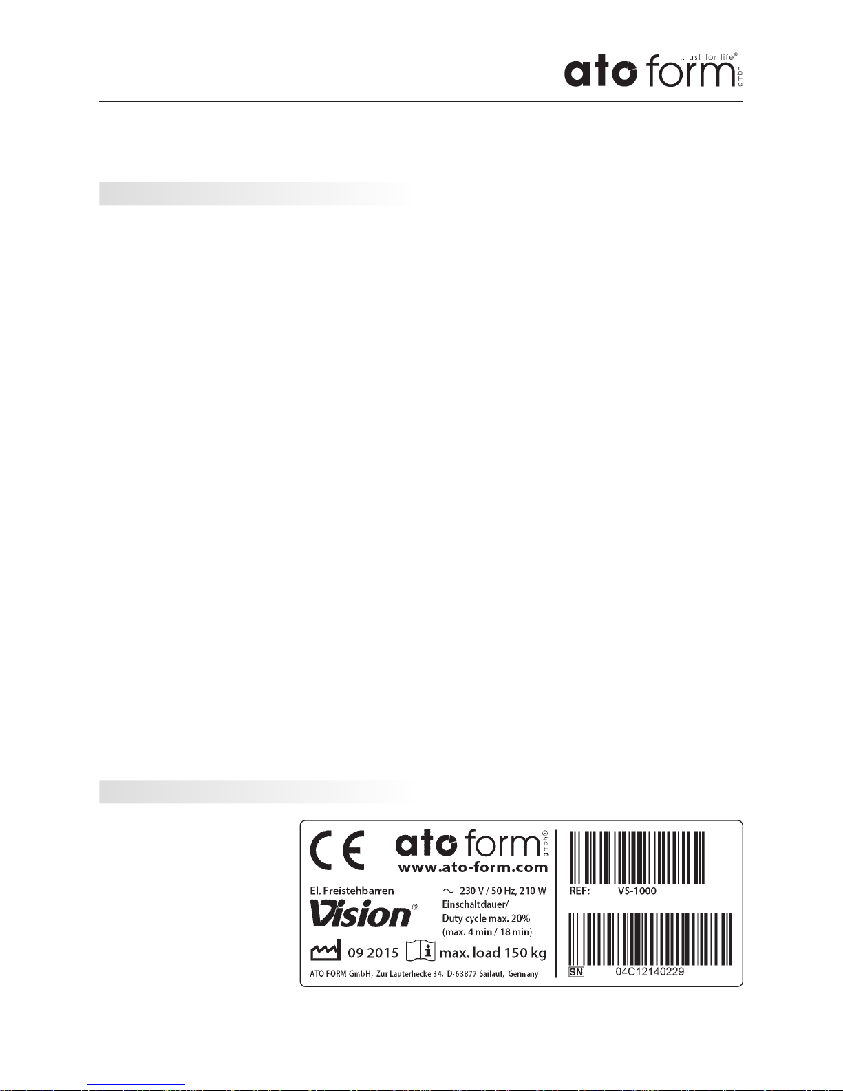
The CE label with details
of the manufacturer, article number, serial number
and production date is located on the inside of the
left vertical guiding post
for table adjustment.
Warranty and product liability
Position of CE-sign
4 Warranty and product liability
5 Position of CE-sign
Page 10

Page 10/36
The VISION consists of a platform with a
motorised system for raising a person.
The VISION was designed and built for:
• Exercise purposes for maintaining or independently upholding an upright standing
body position;
• Maintenance of upright posture by means
of a support belt running under the
coccyx, or optionally available accessories,
as an alternative to autonomous upright
posture.
• Posture is the relationship between
the body and the environment, which
corresponds to the maintenance of a
balance between the elastic forces of the
extensor and flexor muscles as well as the
internal body forces and the forces of the
environment.
The VISION is the aid by which this posture
or this interaction of forces is made possible
and facilitated.
The device must be prescribed by a medical
specialist, who has tested beforehand and
determined if the VISION is suitable for the
individual therapeutic goal of the patient.
Furthermore, the medical specialist has
determined the aid to be suitable according
to measurements, weight and willingness of
the patient to use the aid.
The aid is delivered via an authorised technician in compliance with the requirements
of the country where it is being used and in
strict accordance with the information and
instructions in this manual for adjustments
of the aid according to the measurements of
the user. Only compliance of the regulations
and instructions can lead to positive ergonomically effects.
We wish you every success when using the
standing frame VISION.
The standing frame VISION is an electrical
raising aid for adults.
The aid was developed to allow prolonged
standing where the ability to stand is restricted or lost altogether. Such standing is
indicated for, among other things, preparation for walking training and the recovery of
the ability to walk, balance training, thrombosis prophylaxis, decubitus prophylaxis and
metabolic stimulation. The standing aid can
be used for spacticity inhibition and contracture prophylaxis in cases of paralysis of the
legs; the legs and trunk; the legs, trunk and
arms e.g. due to paraplegia, cerebral palsy,
poliomyelitis or multiple sclerosis.
Indications and prophylaxis
Purpose of use
6 Indications and prophylaxis
7 Purpose of use
Page 11
Page 11/36
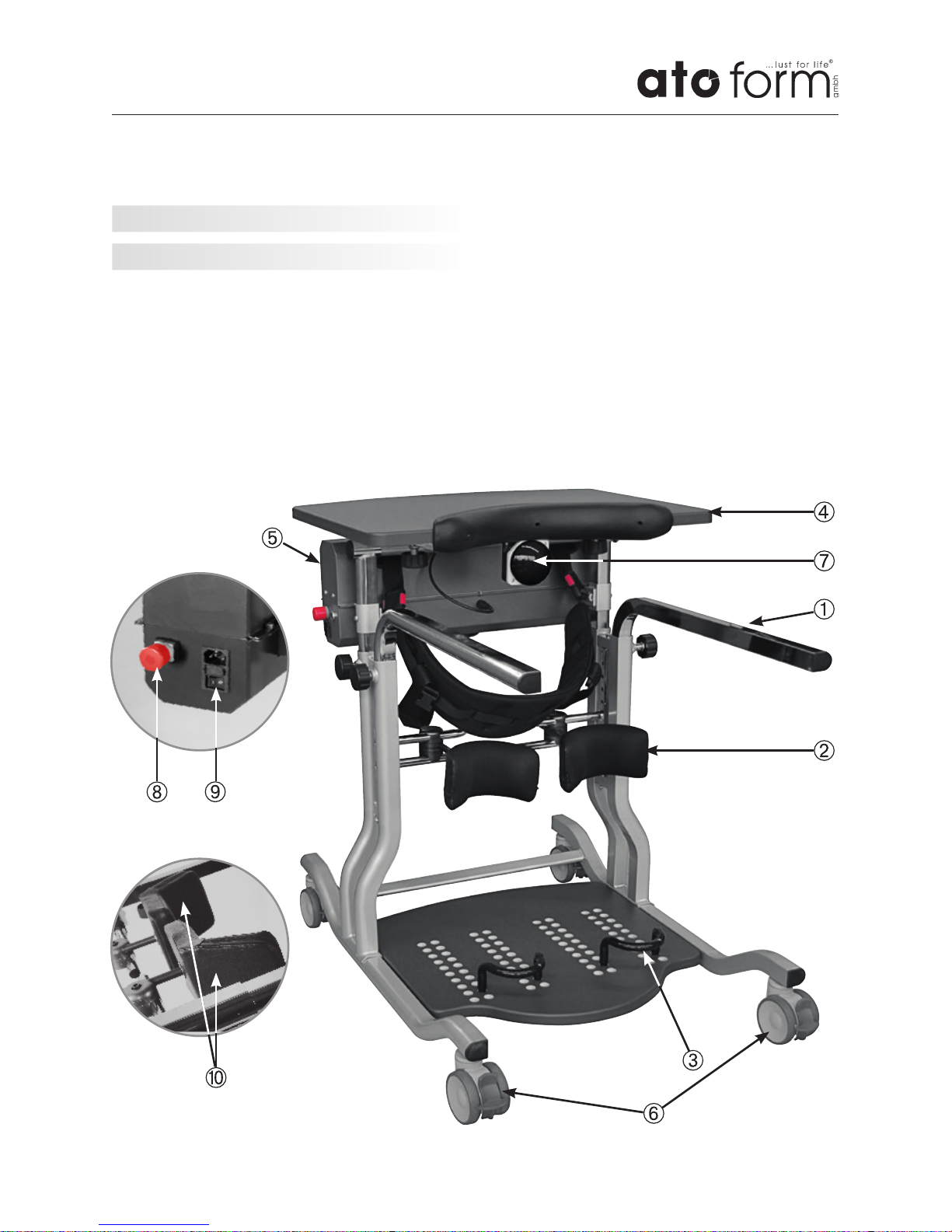
1 Handrail
2 Knee supports; multi-dimensionally
adjustable
3 Heel support
4 Therapy table, adjustable tilt
5 Housing with electrical raising aid
6 Wheels, lockable
7 Belly / limit switch (black button)
8 Emergency stop button
9 Electrical connection with fuse and
On/Off switch
10 Posterior support unit (left / right)
Individually adjustable depth, width and
angle, foldable (accessories)
Product overview
8 Product overview
8.1 Basic model
Page 12

Page 12/36
Product overview
Initial operation
You will find the most current overview of
our extensive offer of VISION accessories
and much more useful information on our
homepage www.ato-form.com.
Please contact us for special requirements of
accessories or for specific problems, which
are not illustrated or described here.
We may already have the right solution for
you.
8.2 Accessories /Options
9 Initial operation
The reseller is to unpack the unit, ensure
that the components and accessories listed
in the scope of delivery are all present and
undamaged, and give the buyer the initial
instructions on use of the aid. Above all the
reseller should read through the complete
present user manual carefully, in order to
then explain it to the customer in detail.
This way, with help of the reseller, the user
as well as the attendant must become familiar with the correct operation of the aid.
Once the demonstration has been completed, the reseller must ensure the user and/or
the assistant have fully understood the basic
functions of the equipment. This is the only
way to prevent the user from dangerous
situations.
The above mentioned requirements must be
observed for first use and also for reuse.
The seller must give instruction for use, as
well as explain the basic functions of the
device according to MPG (medical products
law) to qualified staff.
Page 13

Page 13/36
Assembly and adjustment
First adjustment of device settings
without the patient
To be regulated:
• Height of the electronic device and the
tabletop as well as the handrails
• Knee pads, in height as well as in depth,
width and inclination (multi-dimensionally
adjustable). Reference point: knee.
Following adjustment with the
patient
To be regulated:
• Depth and angle of the therapy table
• Position of the knee pads
• Position of the heel supports (depth)
• Adjustment of the posterior support unit
(multi-dimensionally adjustable) (accessory)
Use
• The settings must be made according to
doctor‘s instructions and according to
indication.
• If possible, hold the remote control in the
direction of the device or motor housing
to operate the up / down function
10 Assembly and adjustment
10.1 Basic model
Preparation:
Unpack the product and remove the packing materials.
The device is completely assembled.
Ensure that the product is complete and
undamaged.
When positioning the limbs or the
patient as shown in the instructions for
use, we point out that we can only provide instructions for device settings.
Concrete statements and instructions
for positioning cannot be derived from
this. This is done by the responsible
therapist or their specialist dealer who,
together with the user, adjusts the
device to suit individual needs. For this
purpose, the described manual adjustment options of the device elements are
used as well as the electrical functions,
which are done in part by means of
remote control or wireless control units.
Page 14
Page 14/36
Assembly and adjustment
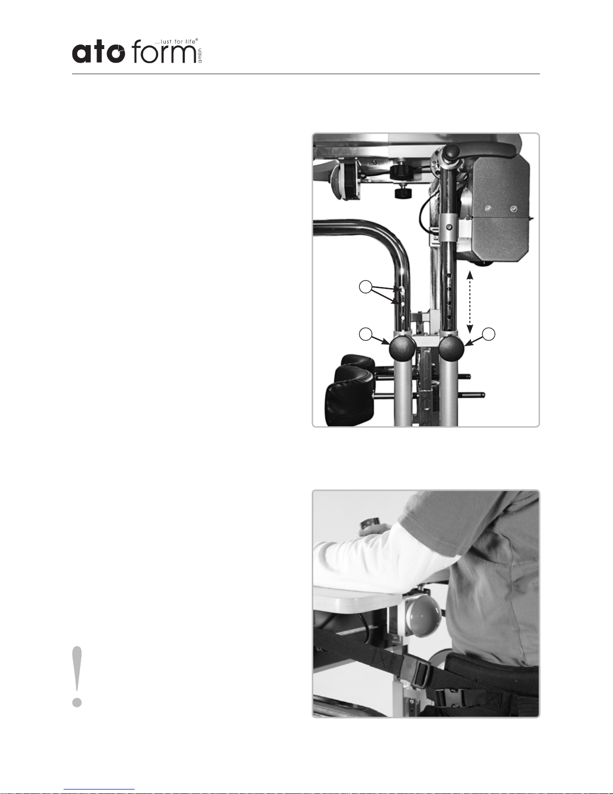
Adjustment of the height of the
handrails
The height of the table surface and the
handrails can be adjusted separately.
• To adjust the handrails loosen the locking
screws (1) on both sides of the Vision
(see illustration) with one turn and pull
the locking screws outwards.
• Adjust the required height with the lock-
ing screws pulled out.
• Make sure that the locking screws click
back into place in the holes (3) and turn
them firmly.
Setting the height of electronic device
and therapy table
The height adjustment of the therapy table
is supported by mounted gas springs.
• The height adjustment of the therapy ta-
ble is supported by mounted gas springs.
• Loosen the locking screws as described
above (2) on both sides of the Vision (see
illustration) for the table.
• Set the required height.
• Make sure that the locking screws click
back into place in the holes and turn them
firmly.
1 2
3
Caution!
In order to ensure sufficient comfort
and support for the user, the work
surface should, in most cases, be set so
that it is below the user‘s elbows.
Page 15
Page 15/36
Assembly and adjustment
C
D
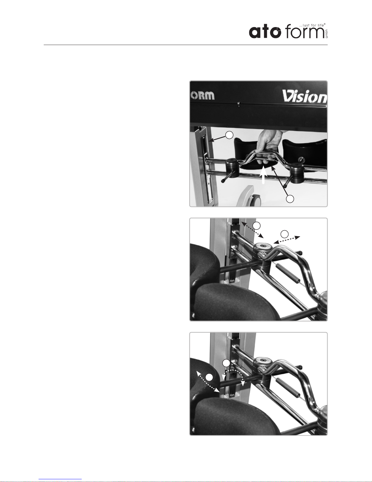
Adjustment of knee supports
Setting height
• The height adjustment is made via the
central handle (1) (see illustration)
• Adjust the height of the knee supports
with the cable pull lifted up to the handle.
• Release the cable pull and ensure that the
bracket for the knee supports securely
clicks into place in the side holes (2).
• Make sure the pads support the knees
below the kneecap.
Setting depth, distance, inclination and
rotation
• Use the hexagonal wrench to loosen the
screws in the discus elements connected
to the knee supports. Hold the knee pad
so that it does not tilt.
• Adjust the depth (A) and/or distance
(B) of the respective knee support and
retighten the screws in the discus elements.
• If necessary, the knee supports on the
discus element can also be individually
tilted (C) or rotated (D).
• When adjusting the knee supports and
the heel rests, ensure that the patient‘s
lower legs are largely vertical after they
have been raised.
A
B
1
2
Page 16
Page 16/36
Assembly and adjustment
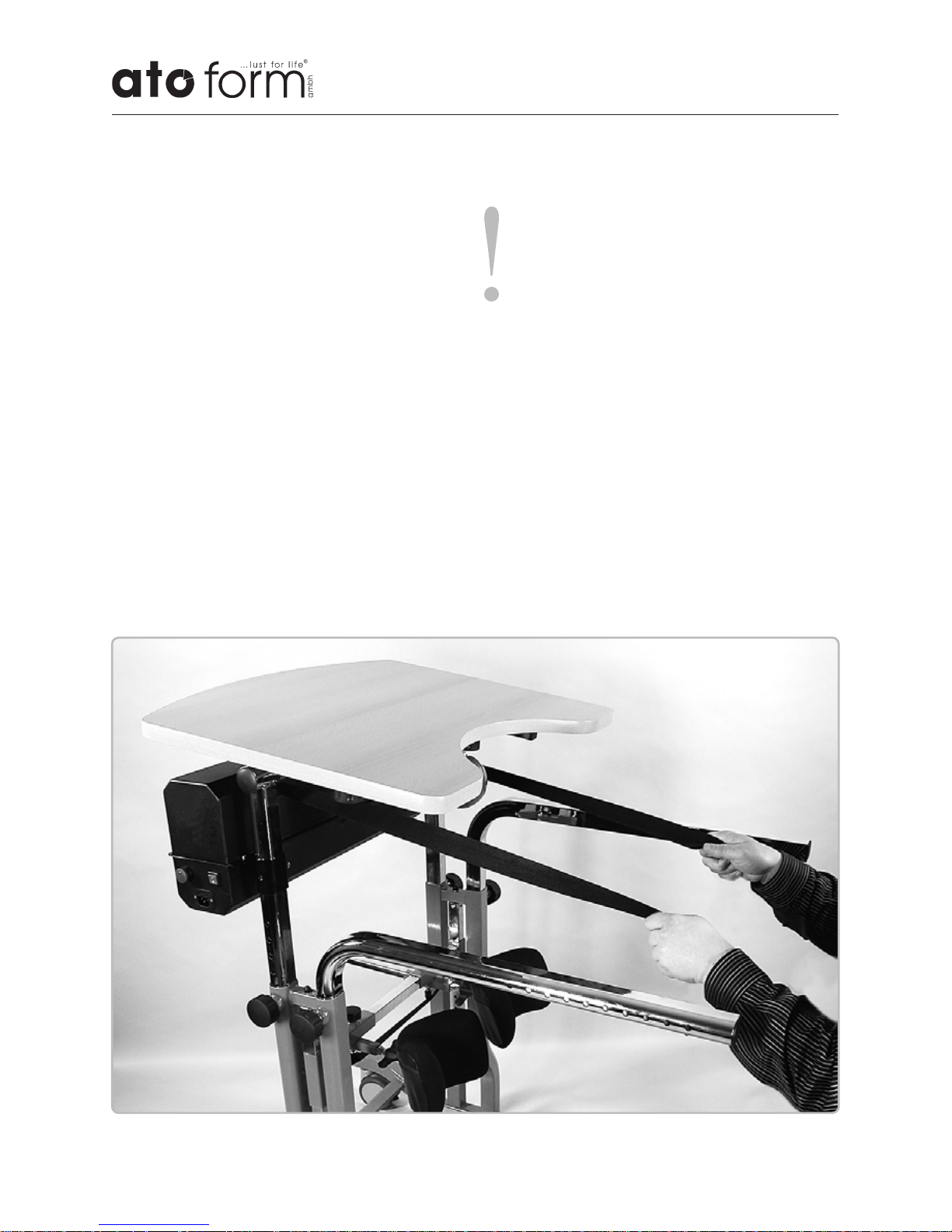
Raising belts
When rolling up the raising belts, it may
happen that they are not pulled in evenly
and are not the same length at the end.
This can happen if the raising belts are
not rolled up with a certain resistance. To
correct this, pull the raising belts out completely and hold them tight as they rewind.
Caution!
When unrolling the raising belts, make
sure that the they are fully extended.
Position the seating belt and attach it
to the rolled up raising belts .
Be careful not to wind the belts without load when the engine is running.
Possible errors due to incorrect rolling
up are uasge errors and are not subject
to the warranty.
Page 17
Page 17/36
Assembly and adjustment
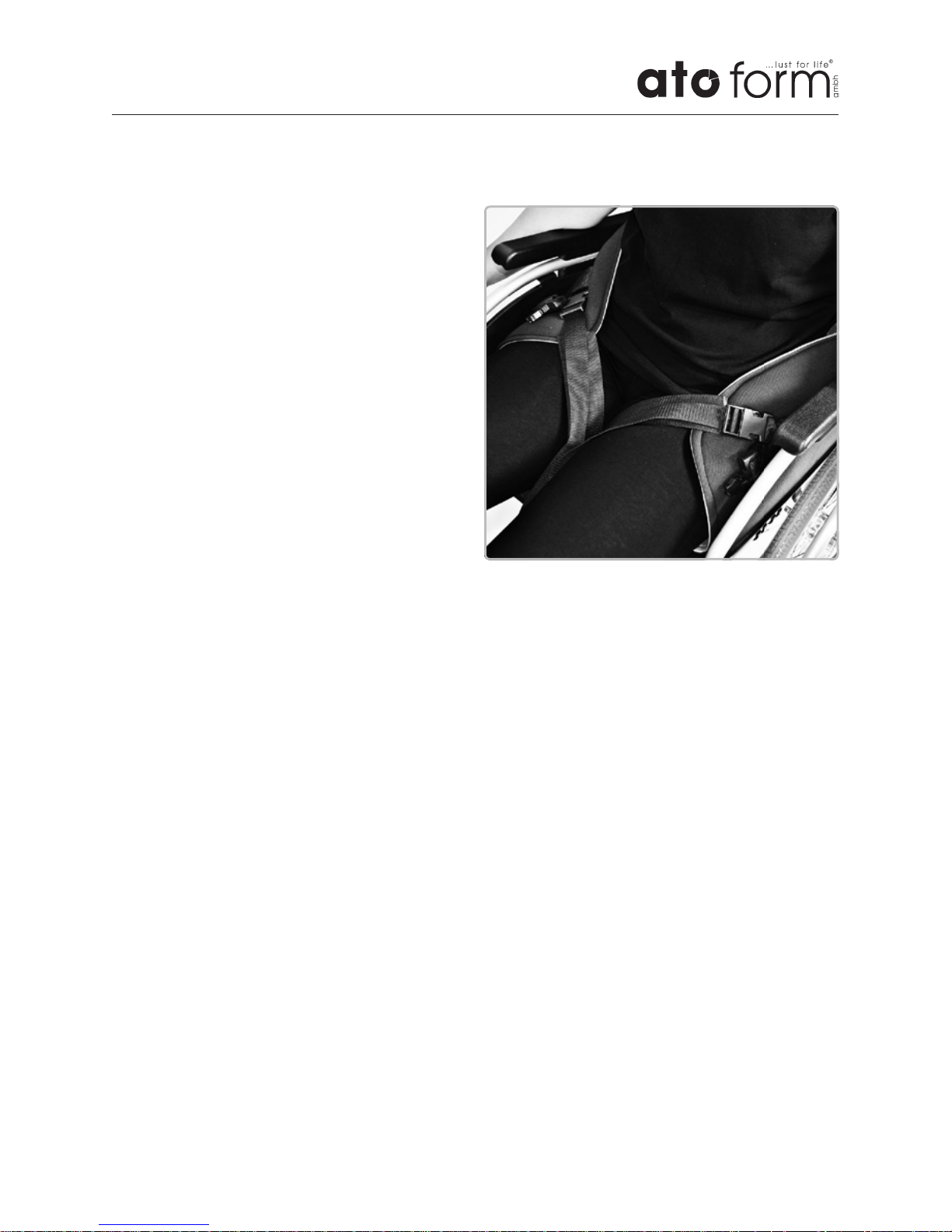
Attaching the sling to the user
• Bring the belt under the buttocks
• Bring the patient‘s upper body forward to
arrange the strap.
• Attaching the groin straps: Pull the straps
under the thighs until they close with the
velcro fastening.
• This process can be done in two ways:
1. Raise the thigh and pull the strap
through.
2. Press the lifting mechanism on the
remote control, lift the person slightly
and then pull the strap under the
thigh.
• The attachment and closing of the
tensioning straps by means of the corresponding safety-tested plastic buckle
[tested to UK Res. M.S.C. 81 (70) § 2.6,
approved for 165 kg/buckle].
Page 18
Page 18/36
Assembly and adjustment
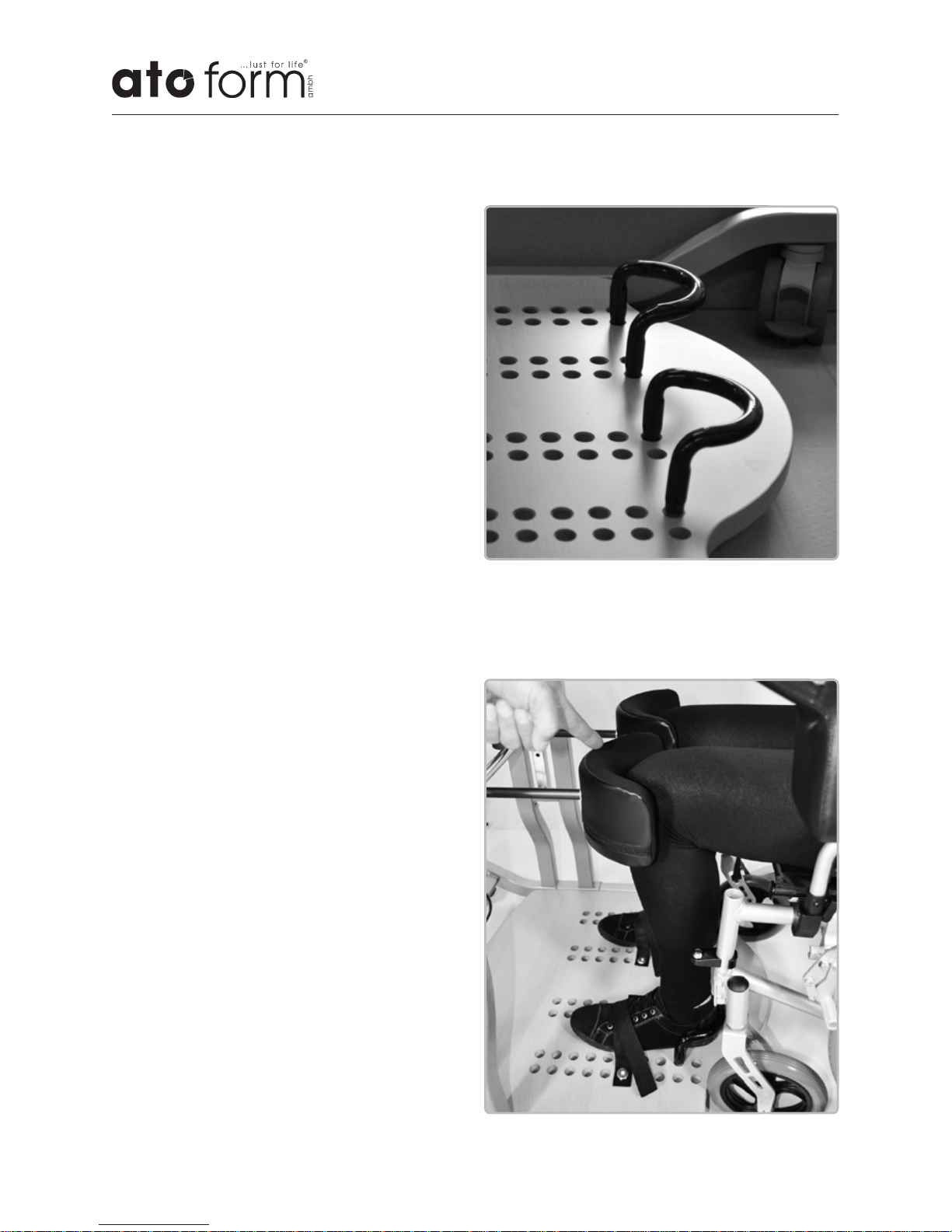
Positioning the wheelchair
• Move the wheelchair close enough to the
unit so that the front wheels touch the
footrest of the VISION.
• Lock the wheels of the wheelchair.
• Always make sure that the wheels of the
VISION are securely locked in place with
the brakes.
Positioning the lower limbs
• Position the patient‘s feet and secure
them with the heel supports.
• When placing the feet, make sure that
the back of the heels are properly placed
in the heel supports and that the knee
supports allow for a slightly bent posture of the knees. The lower legs of the
patient should stand, as far as possible,
vertically after the patient is raised.
• The free play of the knee supports can
be increased or decreased depending on
more or less upright posture (see „Adjustment of the knee supports“).
Mounting the heel support
In most cases, both heel supports should be
placed at the same depth and distance to
the centre.
Page 19
Page 19/36
Assembly and adjustment
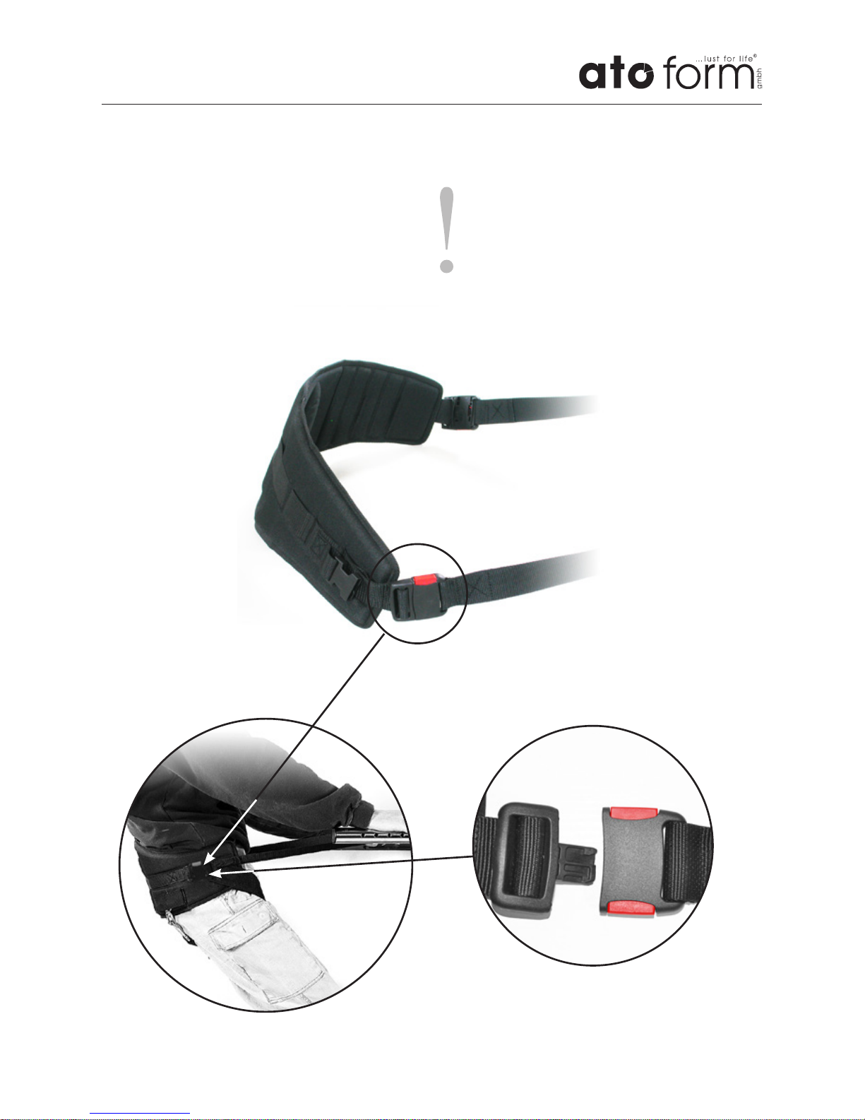
Attaching the sling
The sling is attached to the extended raising belt as shown in the illustration.
Caution!
Before the patient is raised, be sure to
check that the sling is sitting correctly
and properly attached to the raising
belt.
Page 20
Page 20/36
Connection to the electrical power
supply
Make sure that the mains voltage corresponds to the information on the device
label and that the power supply is safely
earthed.
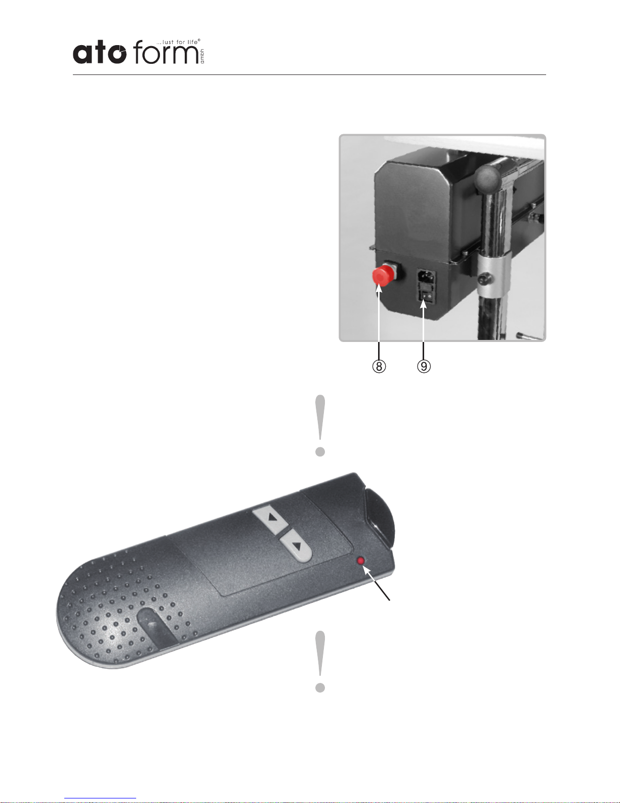
Connect the device to the mains using the
supplied cable. Do not use other cables.
• Switch on the freestanding VISION by
pressing the on / off switch (9) on the left
side of the motor box to „I“ and unlock
the red emergency stop switch (8) by
pulling it.
• Attach the seat belt to the plastic fasteners.
• Bring the belt to approximately the
correct position by using the button
▼(DOWN) on the remote control.
• Lift / lower by remote control.
• End the lifting or lowering process by
releasing the corresponding button.
Front
LED
Down
Up
Caution!
The emergency stop button completely
stops the system. Just push the button
in completely.
Assembly and adjustment
Caution!
In very rare cases, disturbance of the
built-in infrared receiver is possible in
the vicinity of devices with strong light
emission or interference signals. It may
be advantageous in such a situation to
use the wired handset.
Page 21
Page 21/36
Assembly and adjustment
Caution:
During the raising and lowering of the
user and during adjustment, the wheels
absolutely must be locked using the
brakes.
Caution:
When raising or lowering the user,
make sure that the sling is sitting correctly and cannot slip.
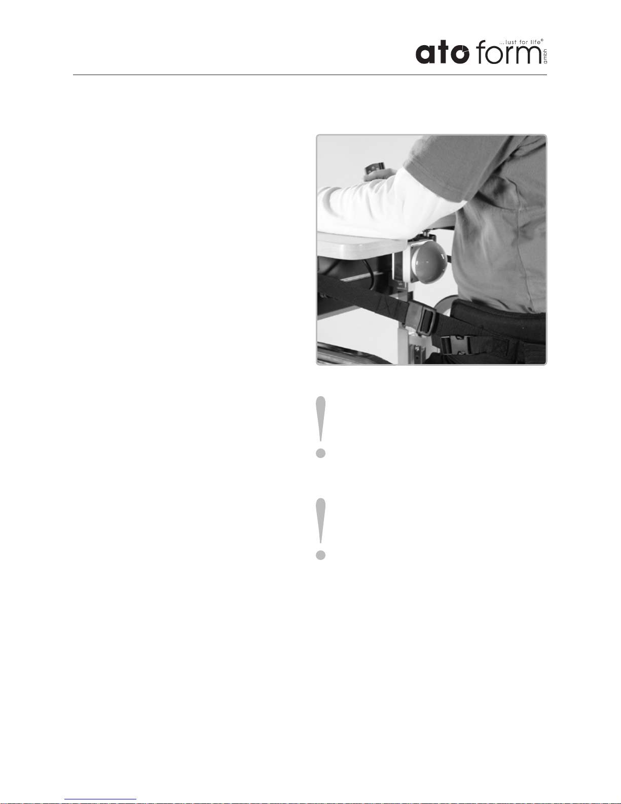
Raising
When the erect position is reached, the
user‘s raising process is stopped by the
belly / limit switch (large button below the
tabletop).
The belly / limit switch is activated by the
body.
Page 22
Page 22/36
Assembly and adjustment
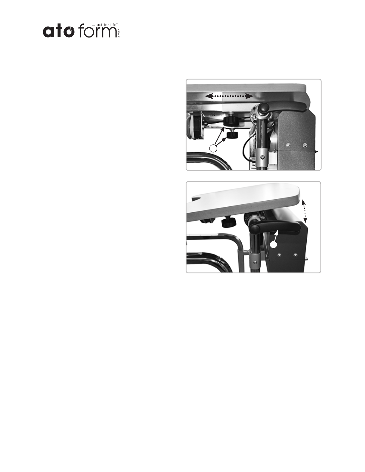
Depth and inclination of the tabletop
Setting the depth
• Release star knobs (1) below the tabletop.
• Set appropriate depth of the therapy
table.
• Retighten star knobs.
Setting the inclination
• Release the lever (2) on the right side
below the table surface.
• Set the desired inclination of the therapy
table.
• Secure the inclination of the therapy table
by locking the lever.
1
2
Page 23
Page 23/36
Assembly and adjustment
10.2 Accessories / Options
Mounting and adjusting
the posterior supports
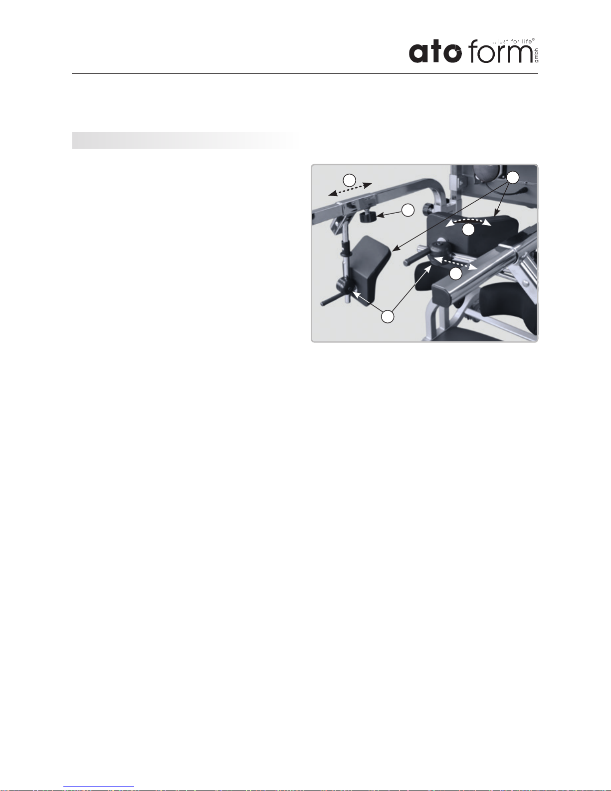
The posterior supports (1) are mounted via
the discus elements (2) on the articulated
transverse guide, which is slid onto the
support bar.
For this purpose, the screws of the discus
elements (2) are removed, the two halfshells are each placed around the tube of
the transverse guide and connected again
by means of the cylinder screw.
The discus element is clamped at the desired
position on the transverse guide by means
of the cylinder screw.
By clamping the discus element on the
transverse guide, the posterior support is
simultaneously held in the desired position.
Setting on the handrail
– Height
• The height of the supports is adjusted
with the height adjustment of the handrails
– Depth (A)
• Loosen the locking screw (3) under the
handrail with one turn and remove.
• Slide the posterior support along the
frame to the position where the patient
needs help.
• Make sure that the locking screws (3)
click back into place in the holes and turn
them firmly.
Settings on the discus element
– Depth
• If necessary, the depth can be readjusted
on the discus element
– Width (B) and angle (C)
• Loosen screw on discus element (2)
• Set necessary distance and angle of the
supports on both sides
• Retighten the screws to secure the position of the supports
3
1
2
A
B
C
Page 24
Page 24/36
Assembly and adjustment
You will find the most current overview of
our extensive offer of VISION accessories
and much more useful information on our
homepage www.ato-form-com.
Belt systems
The different belt systems are used as
described in Section 10.1 („Mounting and
adjusting“) on page 19.
Foot fixation, velcro
Velcro fastening including screw connection
Forefoot fixation
Including retention stop and foot loops
In many cases, it is necessary that the foot
securing system or sockets are placed at the
same depth and distance from the centre.
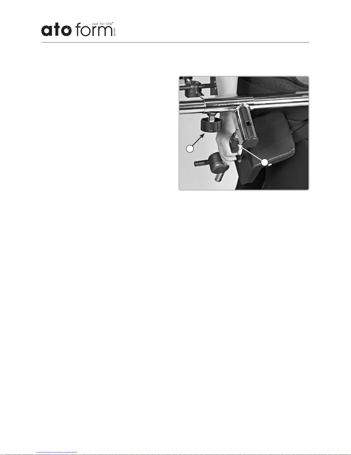
Swivelling the posterior supports
• For patient access, push the plastic handles (D) towards the support and swing
the support down.
D
C
Page 25

Page 25/36
VSJ-1000 Standing frame VISION Junior,
incl. electric belt retractor and wireless remote control
Types and accessories
For the standing frame VISION Junior are currently following accessories available:
VS-0140 Cable remote control
VSJ-0501 Pressure relieving stand up belt
VSJ-0502 Pressure relieving stand up belt, suede inside cover
VSJ-0503 Extended belt system
(composed of stand up belt and abdominal belt)
VSJ-0050 Posterior support unit, left / right
each individually width-, depth- and angle adjustable, hinged
VSJ-0060 Back support with side support and headrest
VS-0070 Forefoot fixations
Including retention stop and foot loops (pair)
VSJ-0080 Cushion for abdomen cut-out „Soft“
VS-0090 Foot fixations, velcro incl. screw connection
11 Types and accessories
11.1 Basic model Vision Junior
11.2 Accessories / Options Vision Junior
Page 26

Page 26/36
Types and accessories
VS-1000 Standing frame VISION,
incl. electric belt retractor and wireless remote control
For the standing frame VISION are currently following accessories available:
VS-0140 Cable remote control
VSJ-0501 Pressure relieving stand up belt
VSJ-0502 Pressure relieving stand up belt, suede inside cover
VSJ-0503 Extended belt system
(composed of stand up belt and abdominal belt)
VSJ-0050 Posterior support unit, left / right
each individually width-, depth- and angle adjustable, hinged
VSJ-0060 Back support with side support and headrest
VS-0070 Forefoot fixations
Including retention stop and foot loops (pair)
VSJ-0080 Cushion for abdomen cut-out „Soft“
VS-0090 Foot fixations, velcro incl. screw connection
11.1 Basic model Vision
11.2 Accessories / Options Vision
Page 27

Page 27/36
VSM-1000 Standing frame VISION Maxi,
incl. electric belt retractor and wireless remote control
Types and accessories
For the standing frame VISION Maxi are currently following accessories available:
VS-0140 Cable remote control
VSJ-0501 Pressure relieving stand up belt
VSJ-0502 Pressure relieving stand up belt, suede inside cover
VSJ-0503 Extended belt system
(composed of stand up belt and abdominal belt)
VSJ-0050 Posterior support unit, left / right
each individually width-, depth- and angle adjustable, hinged
VSJ-0060 Back support with side support and headrest
VS-0070 Forefoot fixations
Including retention stop and foot loops (pair)
VSJ-0080 Cushion for abdomen cut-out „Soft“
VS-0090 Foot fixations, velcro incl. screw connection
11.1 Basic model Vision Maxi
11.2 Accessories / Options Vision Maxi
Further information can be found in our
current product information.
Page 28

Page 28/36
Standing frame VISION Junior VISION VISION Maxi
Article number VSJ-1000 VS-1000 VSM-1000
Footplate ↔ Therapy table
cm 87-10 0 93-120 113-140
Footplate ↔ knee support
cm 30-50 38-56 38-56
Height of handrails (from footplate) cm 69-90 80 -104 10 0-127
Floor ↔ upper edge footplate
cm 8 8 8
Chassis length cm 93 103 126
Overall length (including wheels) cm 99 110 150
Outer frame width (including wheels) cm 68 78 78
Therapy table (breadth x depth) cm 65x60 75x60 75x60
Maximum capacity for the Therapy table kg 50 50 50
Product weight without motor kg 49 49 49
Product weight kg 62 62 62
Maximum load kg 150 150 150
Power supply V 230 230 230
IP Protection IPX4 / I IPX4 / I IPX4 / I
Duty cycles 20% 4min/18 min 20% 4min/18 min 20% 4min/18 min
Fuse control board T 3, 15 A/250 VG T 3, 15 A/250 VG T 3, 15 A/250 VG
Technical changes reserved!
Technical details
12 Technical details
Page 29

Page 29/36
Technical details
Cleaning and disinfection
Construction
The freestanding Vision consists of:
a powder-coated tubular steel frame,
chrome-plated adjustable metal
components, easy-to-clean foam padded
supporting elements, therapy table and
base of beechwood-look MDF, 4 polyamide
double safety castors, each with full brake.
Operating conditions:
Temperature: +5 °C to +40 °C
Relative humidity: 20% bis 90% –
noncondensing
Air pressure: 800 bis 1060 hPA
(Operation in an
estimated height
≤ 2000 m)
13 Cleaning and disinfection
Leftovers, dirt and dust are always to be
removed. Moving parts work easier, if you
apply one drop of oil after cleaning.
Cleaning the metal parts:
The painted and chromed parts of the
standing frame should only be cleaned
using a soft cloth and mild and alcohol
based customary cleaning agents.
Cleaning the wooden surfaces:
The wooden surfaces should be cleaned
using a damp cloth.
Cleaning the rollers/wheels and joints:
Keep these clean at all times; regularly
remove dust, hairs and other accumulating
dirt from rollers.
Cleaning of textiles and imitation leather:
These are best cleaned using water and a
mild detergent.
When using the cleaning agents the
instructions of the manufacturer must be
observed.
Warning
Do not use strong solvents, which
could damage the surface of the device.
The use of a high-pressure cleaner is
not recommended.
Disinfection:
For disinfecting, use household disinfectants
and consider the following indications:
The assistant must wear suitable protective
clothing (for example gloves) in order to
avoid infections.
When using disinfecting agents always
follow the instructions of the manufacturer.
Ensure that the upholstery and wooden
surfaces are kept clean. Urine and
sweat can damage the product.
Page 30

Page 30/36
Maintenance and overhaul
For the protection of the warranty and
safety, it is especially important that the
standing frame with power lift is serviced
regularly once a year from the date of
purchase.
It is recommended to make service
arrangements. The manufacture will gladly
provide the maintenance check list to your
specialist dealer on request.
Please contact your specialist dealer to carry
out corrective maintenance works for your
VISION.
The device should be checked by the
manufacturer at the latest after 5 years.
14 Maintenance and overhaul
Maintance Checklist
Wheels
• No damage or wear
• Fixed seat
Brakes
• Grease and dirt free
• Full braking effect
• No signs of damage or wear
Frame
• Metal parts; no signs of damage or wear,
especially on adjustable parts
• Welds intact
• Fasteners, screws, nuts and springs safely
• Replacement of parts in case of signs of
wear
• No signs of wear or damage to the safety
components for the patient
Upholstery
• No sign of wear
Page 31
Page 31/36
Maintenance and overhaul
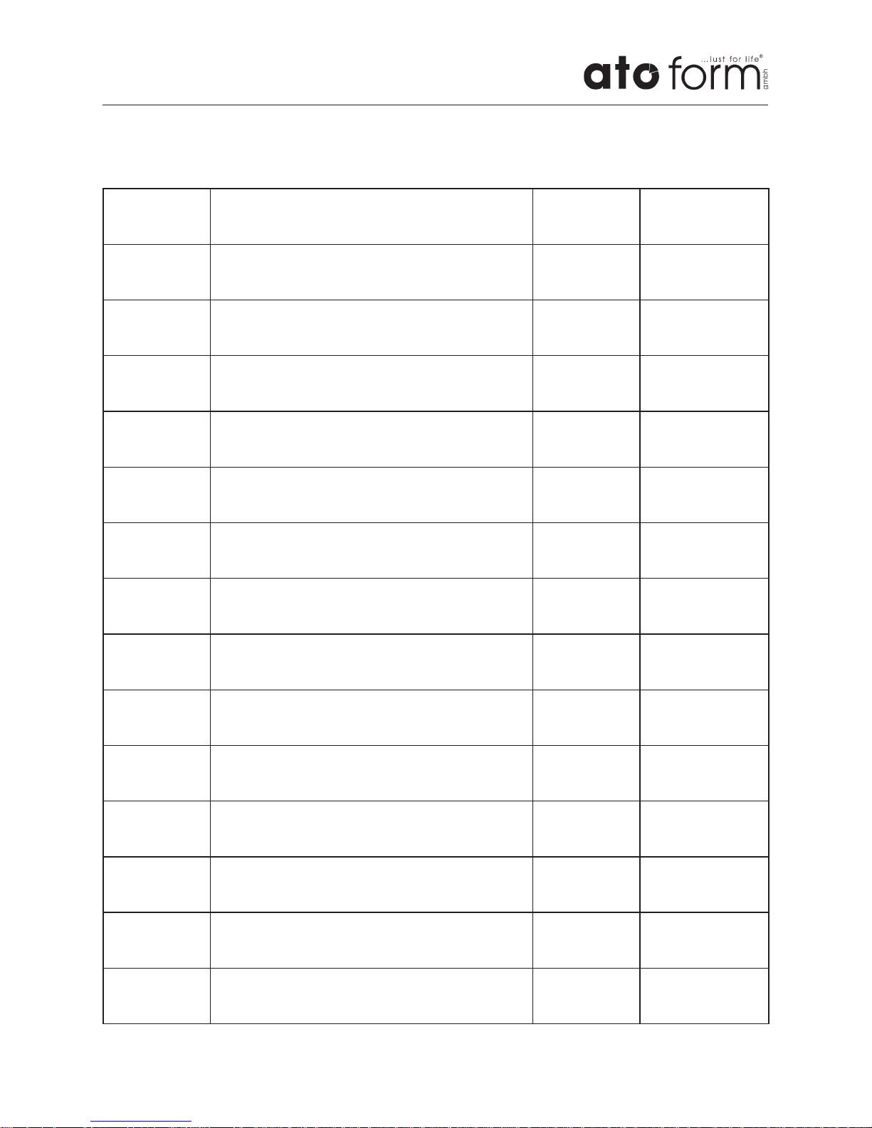
Date Service performed Name Sign
Page 32

Page 32/36
Operating life and Re-use
The VISION is made from high quality
materials and is subject to a continuous
quality control in our house. Because of this
and the solid construction, the expected
operating life of our product is up to 8 years,
depending on the usage intensity and number of re-uses, under normal and compliance with its intended use (according to the
instructions given in our user manual).
The expected operating life does not apply
to wear parts.
The product VISION was designed so it
could be reused after the application of
various measures.
Following measures should be followed:
• Thorough cleaning and disinfecting using
appropriate cleaning agents.
• Replacement of wear parts
• Maintenance, following the maintenance
schedule of the manufacturer or
authorized specialist dealer.
• Preparing accompanying documents and
release for re-use.
15 Operating life and Re-use
Page 33

Page 33/36
If your toilet seat lift VISION cannot be
operated?
Please ensure…..
• The plug is plugged in the socket and is
supplied with power.
• The main switch is activated and there are
batteries in the remote control.
• The emergency-stop-button on the left
side of the Housing is not depressed.
• All plug connections are plugged in
correctly and secured.
Try and shut down the fault.
Failing that, contact your specialist dealer /
reseller.
Spare parts
Only original accessories and original spare
parts may be used. Non-compliance with
these instructions and repairs carried out
or modifications made to the Name or its
parts by unauthorized persons, voids any
warranties.
In these cases, any product liability granted
by the manufacturer (ATO FORM GmbH,
Zur Lauterhecke 34, 63877 Sailauf,
Germany) is voided in advance.
For all questions about spare parts and
accessories contact your specialist dealer or
the ATO FORM-Service +49 6093 944-0.
Spare parts and accessories must not be
removed or replaced while the patient is
using the standing frame!
Keep this operating manual in a safe place,
where you or care and maintenance staff
have access to it.
17 Storage
16 Faults, Repairs, Spare parts
Faults, Repairs, Spare parts
Page 34
Page 34/36
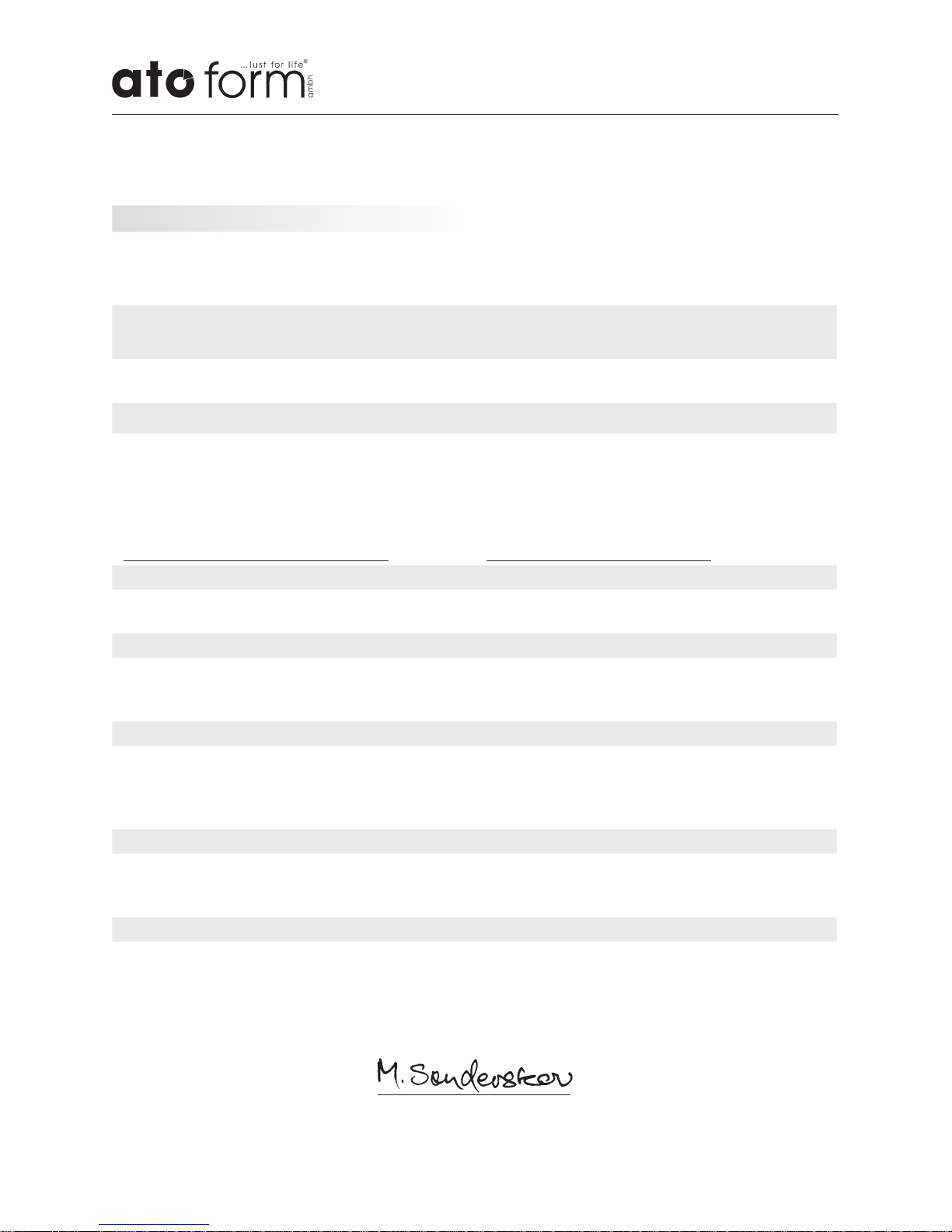
18 Konformitätserklärung / Declaration of conformity
Declaration of conformity
gemäß den Bestimmungen der Richtlinie
93/42/EWG über Medizinprodukte.
According to the regulations of the Council
Directive 93/42/EEC concerning medical devices
Hersteller / Manufacturer:
ATO FORM GmbH, Zur Lauterhecke 34, D-63877 Sailauf
Erklärt, dass das nachfolgend genannte
Medizinprodukt
Declares, that the following medical device
Vision, Freistehbarren Vision, Standing frame
den grundlegenden Anforderungen der
Richtlinie 93/42/EWG über Medizinprodukte
der Klasse I entspricht:
meets the regulations of the Council Directive
93/42/EEC concerning medical devices class I.
Konformitätsbewertungsverfahren gem.
Anhang VII
Conformity Assessment Procedures according
to Annex VII
Angewandte harmonisierte Normen: Harmonised standards applied:
DIN-EN12182:2012
Technische Hilfen für behinderte Menschen –
Allgemeine Anforderungen und Prüfverfahren
Technical aids for disabled persons; General
requirements and test methods
EN ISO 10535:2007
Lifter zum Transport von behinderten Menschen
- Anforderungen und Prüfverfahren (ISO
10535:2006)
Hoists for the transfer of disabled persons Requirements and test methods
(ISO 10535:2006)
EN ISO 60601-1:2006
Medizinische elektrische Geräte;
Teil 1: Allgemeine Festlegungen für die
Sicherheit einschließlich der wesentlichen
Leistungsmerkmale
Medical electrical equipment -
Part 1: General requirements for basic safety
and essential performance
DIN-EN 62366:2008+A1
Medizinprodukte - Anwendung der
Gebrauchstauglichkeit auf
Medizinprodukte (IEC 62366:2007)
Medical devices - Application of usability
engineering to medical devices
(IEC 62366:2007)
EN-ISO 14971:2013
Medizinprodukte - Anwendung des Risikomanagements auf Medizinprodukte
(ISO 14971:20 07, korrig ier te Fa ssung 20 07-10 - 01)
Medical devices; Application of risk
management to medical devices
(ISO 14971:2007, Corrected version 2007-10-01)
Sailauf, 19 Januar 2015 / Januar 19, 2015
Morten Sønderskov / CEO
Page 35
2019-03/St.I-2016-42
In environmental protection matters:
All packaging parts are re-useable. The
cardboard packaging is to be recycled
as waste paper. We therefore use paper
as filler material. Possible used plastic
film of the packaging are made out of
PE and are therefore low in pollutant
and can either be recycled or burnt.
Disposal of battery operated devices
The battery pack must not be
disposed of together with normal
household waste at the end of
its service life. Please observe
the legal requirements in your
area. Your municipal government
and locally based waste disposal
companies will be happy to
provide you with information in
this regard.
Page 36

Complete Range:
■ Walking aids
■ Gait trainer
■ Standing aids
■ Seating aids
■ Hoists
■ Body protection
■ Customized solutions
Thank you for your interest in our products.
For questions please contact ATO FORM GmbH
or your specialist dealer.
Your ATO FORM Team
ATO FORM GmbH, Zur Lauterhecke 34, 63877 Sailauf, GERMANY
Your specialist dealer
 Loading...