

Page 1

V.92 56K Internal Modem User’s Guide
TOSHIBA
C6628-0702M1
Page 2

2
FCC Notice “Declaration of Conformity Information”
This equipment has been tested and found to comply with the limits for a
Class B digital device, pursuant to Part 15 of the FCC rules. These limits
are designed to provide reasonable protection against harmful interference
in a residential installation.
This equipment generates, uses and can radiate radio frequency energy and,
if not installed and used in accordance with the instructions, it may cause
harmful interference to radio communications. However, there is no
guarantee that interference will not occur in a particular installation. If this
equipment does cause harmful interference to radio or television reception,
which can be determined by turning the equipment off and on, the user is
encouraged to try to correct the interference by one or more of the
following measures:
❖ Reorient or relocate the receiving antenna.
❖ Increase the separation between the equipment and receiver.
❖ Connect the equipment to an outlet on a circuit different from that to
which the receiver is connected.
❖ Consult the dealer or an experienced radio/TV technician for help.
NOTE: Only peripherals complying with the FCC Class B limits may be attached
to this modem. Operation with non-compliant peripherals or peripherals not
recommended by Toshiba is likely to result in interference to radio and TV
reception. Changes or modifications made to this equipment not expressly
approved by Toshiba or parties authorized by Toshiba could void the user
authority to operate the equipment.
’s
This device complies with Part 15 of the FCC Rules. Operation is subject to
the following two conditions:
❖ This device may not cause harmful interference.
❖ This device must accept any interference received, including
interference that may cause undesired operation.
Contact:
Toshiba America Information Systems, Inc.
9740 Irvine Blvd.
Irvine, CA 92618-1697
(949) 583-3000
Page 3

Industry Canada Requirement
This Class B digital apparatus complies with Canadian ICES-003.
Cet appareil numérique de la classe B est conformé à la norme NMB-003
du Canada.
Pursuant to FCC CFR 47, Part 68:
When you are ready to install or use the modem, call your local telephone
company and give them the following information:
❖ The telephone number of the line to which you will connect the
modem
❖ The registration number that is located on the device
The FCC registration number of the modem will be found on either
the device which is to be installed, or, if already installed, on the
bottom of the computer outside of the main system label.
❖ The Ringer Equivalence Number (REN) of the modem can vary.
For the REN of your modem, refer to your computer’s user’s guide.
The modem connects to the telephone line by means of a standard jack
called the USOC RJ11C.
Type of service
Your modem is designed to be used on standard-device telephone lines.
Connection to telephone company-provided coin service (central office
implemented systems) is prohibited. Connection to party lines service is
subject to state tariffs. If you have any questions about your telephone line,
such as how many pieces of equipment you can connect to it, the telephone
company will provide this information upon request.
3
Telephone company procedures
The goal of the telephone company is to provide you with the best service it
can. In order to do this, it may occasionally be necessary for them to make
changes in their equipment, operations, or procedures. If these changes
might affect your service or the operation of your equipment, the telephone
company will give you notice in writing to allow you to make any changes
necessary to maintain uninterrupted service.
If problems arise
If any of your telephone equipment is not operating properly, you should
immediately remove it from your telephone line, as it may cause harm to
the telephone network. If the telephone company notes a problem, they
may temporarily discontinue service. When practical, they will notify you
Page 4

4
in advance of this disconnection. If advance notice is not feasible, you will
be notified as soon as possible. When you are notified, you will be given
the opportunity to correct the problem and informed of your right to file a
complaint with the FCC. In the event repairs are ever needed on your
modem, they should be performed by Toshiba Corporation or an authorized
representative of Toshiba Corporation.
Disconnection
If you should ever decide to permanently disconnect your modem from its
present line, please call the telephone company and let them know of this
change.
Fax branding
The Telephone Consumer Protection Act of 1991 makes it unlawful for any
person to use a computer or other electronic device to send any message via
a telephone fax machine unless such message clearly contains in a margin
at the top or bottom of each transmitted page or on the first page of the
transmission, the date and time it is sent and an identification of the
business, other entity or individual sending the message and the telephone
number of the sending machine or such business, other entity or individual.
In order to program this information into your fax modem, you should
complete the setup of your fax software before sending messages.
Instructions for IC CS-03 certified equipment
1 NOTICE: The Industry Canada label identifies certified equipment.
This certification means that the equipment meets certain
telecommunications network protective, operational and safety
requirements as prescribed in the appropriate Terminal Equipment
Technical Requirements document(s). The Department does not
guarantee the equipment will operate to the user’s satisfaction.
Before installing this equipment, users should ensure that it is
permissible to be connected to the facilities of the local
telecommunications company. The equipment must also be installed
using an acceptable method of connection. The customer should be
aware that compliance with the above conditions may not prevent
degradation of service in some situations.
Repairs to certified equipment should be coordinated by a
representative designated by the supplier. Any repairs or alterations
made by the user to this equipment, or equipment malfunctions, may
give the telecommunications company cause to request the user to
disconnect the equipment.
Users should ensure for their own protection that the electrical ground
connections of the power utility, telephone lines and internal metallic
Page 5

2 The user’s guide of analog equipment must contain the equipment’s
3 The standard connecting arrangement (telephone jack type) for this
Copyright
This user’s guide is copyrighted by Toshiba Corporation with all rights
reserved. Under the copyright laws, this user’s guide cannot be reproduced
in any form without the prior written permission of Toshiba. No patent
liability is assumed, however, with respect to the use of the information
contained herein.
© 2002 by Toshiba Corporation. All rights reserved.
5
water pipe system, if present, are connected together. This precaution
may be particularly important in rural areas.
Caution: Users should not attempt to make such connections
themselves, but should contact the appropriate electric inspection
authority, or electrician, as appropriate.
Ringer Equivalence Number (REN) and an explanation notice similar
to the following:
The Ringer Equivalence Number (REN) of this device can vary.
For the REN number of your modem, refer to your computer’s user’s
guide.
NOTICE: The Ringer Equivalence Number (REN) assigned to each
terminal device provides an indication of the maximum number of
terminals allowed to be connected to a telephone interface. The
termination on an interface may consist of any combination of devices
subject only to the requirement that the sum of the Ringer Equivalence
Numbers of all the devices does not exceed 5.
equipment is jack type(s): USOC RJ11C.
Export Administration Regulation
This document contains technical data that may be controlled under the
U.S. Export Administration Regulations, and may be subject to the
approval of the U.S. Department of Commerce prior to export. Any export,
directly or indirectly, in contravention of the U.S. Export Administration
Regulations is prohibited.
Disclaimer
This user’s guide has been validated and reviewed for accuracy. The
instructions and descriptions it contains are accurate for the Toshiba
internal modem at the time of this user’s guide
succeeding products and user’s guides are subject to change without notice.
’s production. However,
Page 6

6
Toshiba assumes no liability for damages incurred directly or indirectly
from errors, omissions or discrepancies between the modem and the user’s
guide.
Trademarks
Microsoft and Windows are registered trademarks of Microsoft
Corporation.
Microcom and Microcom Networking Protocol are registered trademarks
of Microcom, Inc.
Hayes is a registered trademark of Hayes Microcomputer Products Inc.
MNP is a trademark of Microcom Systems, Inc.
Page 7

Contents
Introduction ..............................................................12
Conventions........................................................... 12
Features ................................................................. 14
Function charts ...................................................... 17
Chapter 1: Modem On Hold....................................... 19
Using Modem On Hold........................................... 20
Answering an incoming voice call.................... 20
Placing an outgoing voice call.......................... 22
Viewing Call History ......................................... 25
Configuring Modem On Hold ................................. 25
Configuring Modem On Hold settings.............. 26
Enabling/Disabling the Modem On Hold
autorun status............................................ 28
Adding and removing the Modem On Hold
icon from the system tray .......................... 28
Locating the Modem On Hold application version.. 29
Chapter 2: Function Check ........................................ 31
Running diagnostics .............................................. 31
Determining current connection protocol .............. 38
7
Page 8

Contents
8
Chapter 3: Using the Internal Modem ....................... 44
Connection procedures .......................................... 44
Analog or digital?............................................. 45
Connecting the internal modem ....................... 45
Disconnecting the internal modem .................. 46
Basic operation ...................................................... 47
Connecting to a telephone line ......................... 47
Direct access line ............................................. 47
Extension line................................................... 48
Receiving a call ................................................ 49
Terminating a call............................................. 49
Setting the data flow control ............................ 49
Facsimiles ........................................................ 50
Chapter 4: AT Commands ......................................... 51
AT command formats ............................................ 51
+++ Escape sequence ...................................... 52
A/ Repeat last command.................................. 52
A Answer command......................................... 52
Bn Communication standard setting................ 52
Dn Dial ............................................................. 53
En Echo command........................................... 54
Hn Hook control............................................... 55
In Request ID information................................ 55
Ln Monitor speaker volume ............................. 60
Mn Monitor speaker mode............................... 60
Nn Modulation handshake ............................... 61
On Return online to data mode ........................ 61
P Select pulse dialing....................................... 62
Qn Result code control .................................... 62
T Select tone dialing......................................... 62
Vn DCE response format.................................. 62
Wn Result Code Option.................................... 63
Page 9

Contents
9
Xn Result code selection, call progress
monitoring ................................................. 63
Extended result codes...................................... 64
Dial tone detect ................................................ 64
Busy tone detect .............................................. 64
Zn Recall stored profile .................................... 65
&Cn Data Carrier Detect (DCD) control ............ 65
&Dn Data Terminal Ready (DTR) control ......... 66
&F Load factory settings.................................. 66
&Gn V.22bis guard tone control....................... 67
&Kn Local flow control selection ..................... 67
&Pn Select Pulse Dial Make/Break Ratio ......... 68
&Tn Self-test commands ................................. 68
&V View active configuration and stored
profile ........................................................ 69
&W Store current configuration....................... 69
&Y Select stored profile for hardware reset ..... 69
&Zn=x Store telephone number ....................... 70
\Nn Error control mode selection ..................... 70
Qn Local flow control selection........................ 71
\Vn Protocol result code .................................. 71
%Cn Data compression control ....................... 72
-V.90=<n> ........................................................ 72
+DS44 V.44 Data Compression Command....... 73
+MS Command................................................ 74
+PCW Command ............................................. 77
+PIG Command ............................................... 78
+PMH Command ............................................. 79
+VCID Command ............................................. 79
Chapter 5: S-Registers .............................................. 81
S-Register values................................................... 82
S0 Auto answer ring number ........................... 82
S1 Ring counter............................................... 82
Page 10

Contents
10
S2 AT escape character (user-defined) ............ 83
S3 Command line termination character
(user-defined) ............................................ 83
S4 Response formatting character
(user-defined) ............................................ 83
S5 Command line editing character
(user defined) ............................................ 84
S6 Wait before dialing...................................... 84
S7 Connection completion time-out................. 85
S8 Comma pause time..................................... 85
S11 DTMF dialing speed .................................. 85
S12 Escape guard time .................................... 86
S37 Dial line rate.............................................. 86
AT command set result codes................................ 87
Chapter 6: Test Function ........................................... 92
Test description...................................................... 92
Testing procedure .................................................. 93
Chapter 7: MNP and V.42.......................................... 95
Error-correction overview ...................................... 95
MNP error correction ....................................... 95
V.42 error correction ........................................ 96
Operation modes ................................................... 96
Normal mode ................................................... 96
Reliable mode .................................................. 96
Commands (\Nn) ............................................. 97
Flow control ........................................................... 97
Serial port flow control .................................... 98
XON/XOFF flow control (software) ................... 98
CTS/RTS two-way flow control (hardware)...... 99
Commands (\Qn, &Kn) .................................... 99
Modem port flow control ............................... 100
Data compression ................................................ 100
Page 11

Contents
11
Commands (%Cn) ......................................... 100
Appendix A: Specifications...................................... 101
Network control unit (NCU) ................................. 101
Communication specifications ............................. 102
Appendix B: Communication Conditions ................. 103
Communication parameters................................. 103
Telephone line types............................................. 103
Connectable lines (2-wire) ............................. 104
Unconnectable lines (4-wire) ......................... 104
Dial modes........................................................... 104
Glossary .................................................................. 105
Index .......................................................................117
Page 12

Introduction
Congratulations on becoming the owner of a V.92 56K-compliant
internal modem offering advanced functions for fax and data
communication. This user’s guide provides detailed information
on features, operation and technical specifications of your internal
modem.
Conventions
This user’s guide uses the following formats to describe, identify,
and highlight terms and operating procedures.
Abbreviations
On first appearance, and whenever necessary for clarity,
abbreviations are enclosed in parentheses following their
definition; for example: Read Only Memory (ROM). Acronyms
are also defined in the Glossary.
12
Page 13

Introduction
Conventions
13
Keys
The keyboard keys are used in the text to describe many computer
operations. A distinctive typeface identifies the key top symbols as
they appear on the keyboard. For example,
Enter key.
Enter identifies the
Key operation
Some operations require you to simultaneously use two or more
keys. We identify such operations by the key top symbols
separated by a plus sign (+). For example,
hold down
hold down the first two and at the same time press the third.
Ctrl and at the same time press C. If three keys are used,
ATD T Text you are to type in is represented in the type
face you see to the left.
Ctrl + C means you must
Display
ABC Text generated by the computer that appears on
its display screen is presented in the type face
you see to the left (bold).
Page 14

14
Messages
Messages are used in this user’s guide to bring important
information to your attention. Each type of message is identified
as shown below.
Features
Introduction
Features
CAUTION: This icon indicates the existence of a hazard that could
result in damage to equipment or property if the safety instruction
is not observed.
NOTE: This icon indicates information that relates to the safe
operation of the equipment or related items.
The V.92 56K internal modem provides capability for facsimile
transmissions and standard computer-to-computer data
communications, at a rate of up to 53,000 bits per second
(downstream). It supports the following V.92 features:
❖ Fast Connect—shortens connection times up to 25 percent, by
storing phone line characteristics.
❖ Modem On Hold (MOH)—enables you to talk on the
telephone while connected to the Internet, using the same
telephone line. This feature requires ISP support and Call
Waiting/Caller ID Service. It also requires the Modem On
Hold application, which comes preinstalled on your
computer.
❖ PCM Upstream—transmits up to 48,000 bits per second
upstream to host modems that support the V.92 protocol.
Page 15

Introduction
Features
❖ Data Compression—increases transmission speeds using the
new V.44 compression algorithm, which is optimized for
World Wide Web browsing. The modem also supports MNP5
and V.42bis data compression protocols.
The internal modem has a modem port (RJ11) for connecting to an
analog telephone line.
CAUTION: Connect the internal modem ONLY to an analog line,
not to a digital line. For more information, see “Connection
procedures” on page 44.
Due to FCC limitations, speeds of 53 kbps are the maximum
permissible transmission rates during downloads. Actual data
transmission speeds will vary depending on line conditions. Many
users will experience throughput in the range of 32 to 44 kbps
under normal conditions, depending on telephone line quality.
To achieve a V.92 56K connection, both your modem and the host
modem (typically at an ISP) must be V.92 56K modems. As many
ISPs do not yet support the V.92 protocol, most connections will
be V.90 56K connections.
15
V.92 connections also require a phone line that supports the V.92
protocol. Some phone lines will not support V.92 or V.90 56K
connections at all, either because of quality impairments or
additional analog-to-digital conversions (for example, PBX
systems).
When a PCM upstream connection is not possible, the modem
automatically uses the default V.34 protocol for “upstream” data
transmission, which supports connection rates of up to 33,600 bits/
second.
Page 16

16
Introduction
Features
56K data communication
Fax capability You can use the internal modem to transmit
Standard commands
Error control This feature assures accurate data transmis-
The internal modem uses the V.92 protocol to
connect to host V.92 modems at data rates of
up to 53,000 bits per second (bps). It uses the
V.90 protocol to connect at data rates of up to
53,000 bps when connecting to a V.90 host
modem. For connections that do not support
either the V.90 or V.92 protocol, the internal
modem uses the ITU standard V.34 protocol
to connect at rates of up to 33,600 bits per
second. The internal modem also supports all
of the earlier, lower-speed ITU/CCITT
modem protocols.
and receive facsimiles at rates of up to 14,400
bps. The internal modem supports Class 1 fax
transmission.
The internal modem is compatible with the
industry standard Hayes
S-Register settings.
sion even over telephone lines subject to
noise interference. The internal modem uses
Microcom Networking Protocol
and V.42 error correction.
®
AT commands and
®
4 (MNP4)
Data compression Compression can greatly increase data
throughput. The internal modem supports the
new V.44 compression protocol, which is
optimized for World Wide Web browsing. It
also supports MNP5 and V.42bis data compression protocols.
Serial port access The internal modem frees your computer’s
serial port for connection of a serial mouse,
serial printer or other serial device.
Page 17

Introduction
Function charts
Ring indicator The computer can be powered on automati-
cally when the modem answers a call. This
feature is available only when the computer is
in Resume/Standby mode. Refer to your computer’s documentation for details on ring
indicator power on.
17
Standby/Hibernate
Modem On Hold Enables you to talk on the telephone while con-
Fast Connect Shortens connection times up to 25 percent, by
PCM upstream Transmits up to a maximum rate of 48,000 bits
When the computer is set to Standby or
Hibernate, the modem settings automatically
resume when you turn on the power. Refer to
your computer’s documentation for details on
Standby/Hibernate modes.
nected to the Internet, using the same telephone
line. This feature requires ISP support and Call
Waiting/Caller ID Service. The phone line must
support Type 2 Caller ID (CID).
storing phone line characteristics.
per second upstream to host V.92 modems that
support this feature.
Function charts
The modem supports these communication protocols:
Functions available in all operating systems
Function Remarks
Data V.92/V.90 From 32 Kbps to 56 Kbps
V.34 From 2400 bps to 33.6 Kbps
V.32bis 4800, 7200, 9600 bps, 12, 14.4 Kbps
Page 18

18
Introduction
Function charts
Functions available in all operating systems (Continued)
Function Remarks
V.32 4800, 9600 bps
V.22bis 1200, 2400 bps
V.22 1200 bps
V.23 75, 600, 1200 bps
V.21 300 bps
BELL212A 1200 bps
BELL103 300 bps
MNP5 Data compression
MNP4 Error control
V.44 Data compression
V.42bis Data compression
V.42 Error control
Fax V.17 7200, 9600 bps, 12, 14.4 Kbps
V.29 7200, 9600 bps
V.27ter 2400, 4800 bps
V.21 ch2 300 bps
EIA-578 Class 1 command set for fax
Definition: bps stands for bits per second.
Page 19

Chapter 1
Modem On Hold
Your computer comes with the Modem On Hold application
preinstalled. This application enables you to answer
incoming voice calls or make outgoing voice calls while
maintaining your Internet connection, by putting the Internet
connection on hold.
To use the Modem On Hold feature, you must have Call
Waiting service and an ISP that supports the V.92 modem
protocol. You must also have Caller ID service, if you want
the application to display the identity of incoming calls. The
phone line must support Type 2 Caller ID.
For V.90 connections, which do not support the Modem On
Hold feature, the Modem On Hold application displays the
incoming call information so that you can choose to either
ignore it, or disconnect the Internet connection to answer the
call. The application can also be configured to automatically
disconnect your Internet connection so that you can answer
incoming voice calls, in case you do not have Call Waiting
service.
19
Page 20
Modem On Hold
20
Using Modem On Hold
The Modem On Hold application comes configured to
automatically launch when you start the computer, displaying
an icon on the system tray. However, you can change this
configuration. See “Configuring Modem On Hold” on
page 25 for instructions.
Using Modem On Hold
The Modem On Hold application pops up the V.92 Modem
On Hold dialog whenever an incoming voice call is detected,
or you place an outgoing voice call while connected to the
Internet. This dialog displays information about the call in a
Call Status box.
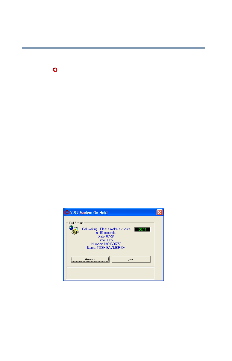
Answering an incoming voice call
When the modem detects an incoming voice call during an
Internet connection, the V.92 Modem on Hold dialog appears.
The Call Status box indicates that a call is waiting. If you
have Caller ID, the dialog also displays the phone number
and identity of the incoming call.
Sample Incoming voice call dialog box
1 To ignore an incoming call, click Ignore, or simply
ignore the call.
If you ignore the call, it will continue to ring until the
timer expires in 15 seconds.
Page 21
Modem On Hold
Using Modem On Hold
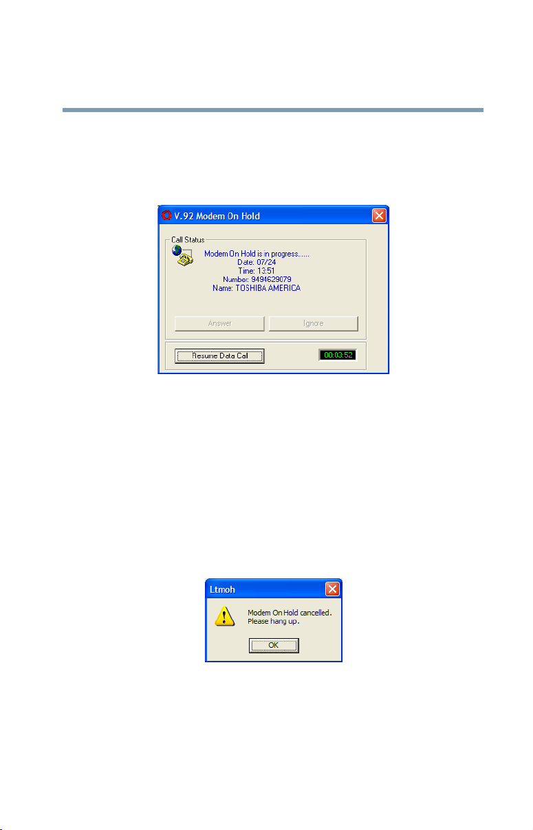
2 To answer an incoming call, click Answer, then pick up
your telephone handset.
The Call Status box indicates that the Internet connection
is on hold while you complete your voice call.
Sample Modem On Hold in progress dialog box
3 To maintain the Internet connection, you must complete
the voice call before the Modem On Hold timer expires.
21
The application displays the timer in the lower right
corner. The timeout value is determined by your ISP.
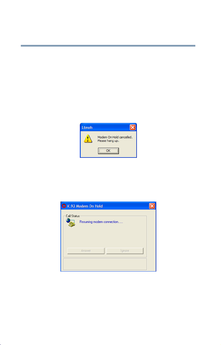
4 To end your voice call and resume your Internet
connection, click Resume Data Call.
A dialog displays, indicating that the Modem On Hold
has been cancelled and instructing you to hang up.
Sample Modem On Hold cancelled dialog box
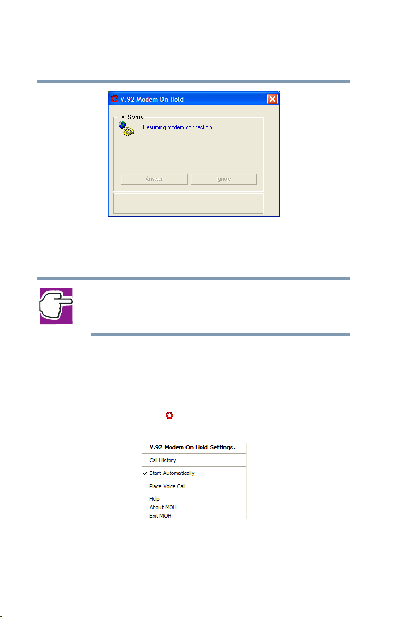
5 Click OK.
The Call Status box indicates that it is resuming the
modem (Internet) connection.
Page 22
22
Modem On Hold
Using Modem On Hold
Sample Resuming modem connection dialog box
The modem connection is automatically renegotiated and
your Internet connection resumes.
NOTE: A “Call Canceled” message may display. If this occurs, wait
a few seconds while the modem automatically redials and
reestablishes your Internet connection.
Placing an outgoing voice call
To use this function, your phone line must support three-way
calling service.
1 Right-click the icon, located on the system tray, to
display the modem popup window.
Sample modem popup window
2 Click Place Voice Call.
Page 23
Modem On Hold
Using Modem On Hold
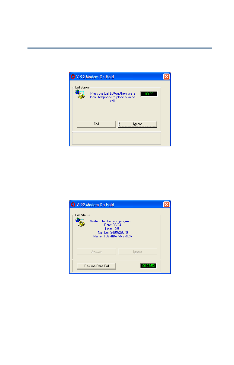
The V.92 Modem On Hold dialog appears, instructing
you to click the Call button.
Sample Placing a voice call dialog box
3 Before the 15-second timer runs out, click Call.
Otherwise, click Ignore to cancel the call.
The Call Status box indicates that the Internet connection
is on hold while you complete your voice call.
23
Sample Modem On Hold in progress dialog box
4 Pick up your telephone handset and place your voice call.
5 To maintain the Internet connection, you must complete
the voice call before the Modem On Hold timer expires.
The application displays the timer in the lower-right
corner. The timeout value is determined by your ISP.
Page 24
24
Modem On Hold
Using Modem On Hold
6 To end your voice call and resume your Internet
connection, wait until the incoming caller has hung up,
then click Resume Data Call.
If you hang up before the incoming caller, a “Call
Cancelled” message may display. If this occurs, wait a
few seconds while the modem automatically redials and
reestablishes your Internet connection.
A dialog displays, indicating that the Modem On Hold
has been cancelled and instructing you to hang up.
Sample Modem On Hold cancelled dialog box
7 Click OK.
The Call Status box indicates that it is resuming the
modem connection.
Sample Resuming modem connection dialog box
The modem connection is automatically renegotiated and
your Internet connection resumes.
Page 25
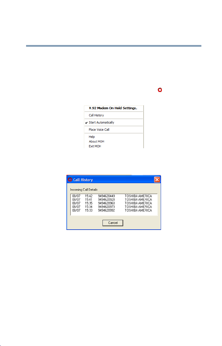
Viewing Call History
The Modem On Hold application provides a log of the last
ten incoming calls. The log includes the date, time, phone
number, and Caller ID (if you have Caller ID service).
1 To view the call history, right-click the icon, located
on the system tray, to display the modem popup window.
Sample modem popup window
2 Click Call History to display the Call History log.
Modem On Hold
Configuring Modem On Hold
25
Sample Call History log
Configuring Modem On Hold
The Modem On Hold application comes preconfigured with
Call Waiting, Caller ID, and the Modem On Hold Feature
enabled. If your configuration does not match this, you can
change the default configuration. You can also configure the
application so that it does not automatically run when you
start your computer.
Page 26
Modem On Hold
26
Configuring Modem On Hold
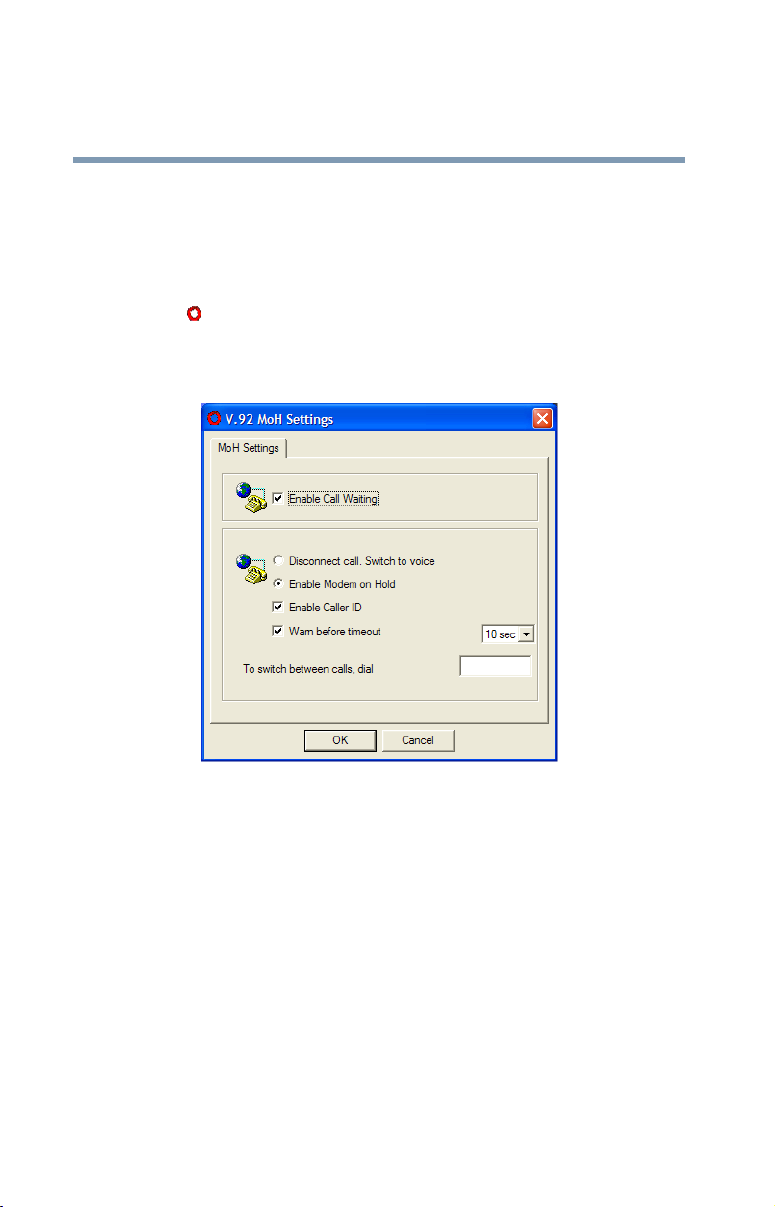
Configuring Modem On Hold settings
You configure Modem On Hold settings from the V.92 MoH
Settings dialog.
1 To open the V.92 MoH Settings dialog, double-click the
icon, located on the system tray in the lower-right
corner of your desktop.
The V.92 MoH Settings dialog appears.
Sample V.92 MoH Settings dialog box
2 If you do not have Call Waiting service, clear the Enable
Call Waiting check box.
All of the other settings in this dialog become
unavailable. If you do not have Call Waiting, the modem
will still display a message when it detects an incoming
call during an Internet connection, however you will not
be able to use the Modem On Hold feature to answer that
call without losing the Internet connection.
Page 27

Modem On Hold
Configuring Modem On Hold
3 If you do not want the Modem On Hold feature enabled,
select Disconnect call. Switch to voice.
When the modem detects an incoming voice call during
an Internet connection, it disconnects the Internet
connection so that you can answer the voice call.
4 If Modem On Hold is enabled, you can select or clear the
Enable Caller ID check box to match your telephone
service.
5 To disable the warning that displays before the Modem
On Hold timer expires (disconnecting an incoming or
outgoing voice call if not completed), clear the Warn
before timeout check box.
6 To change the Modem On Hold warning timer value,
select a value from the Warn before timeout dropdown
box.
You can set the timer from 10 to 60 seconds, in intervals
of 10 seconds.
27
7 If your phone system requires a number to be dialed to
switch between voice and data calls, enter that number in
the To switch between calls, dial box.
If your phone system requires one number to switch from
voice to data and a different number to switch from data
to voice, enter both numbers in the box, separated by a
comma.
8 Click OK to close the dialog and save your changes.
Page 28

Modem On Hold
28
Configuring Modem On Hold
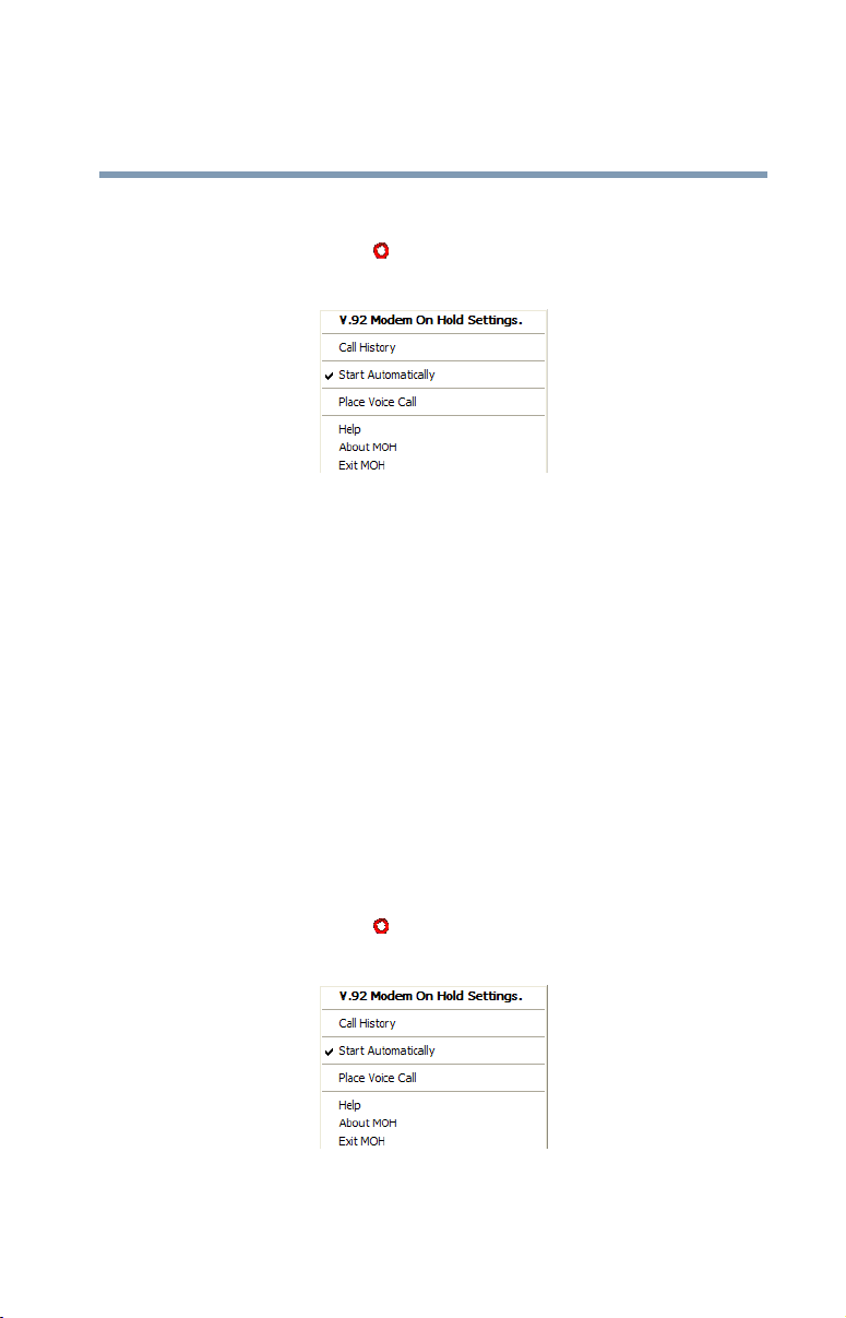
Enabling/Disabling the Modem On Hold autorun status
1 Right-click the icon, located on the system tray, to
display the modem popup window.
Sample modem popup window
2 If Start Automatically is checked, you can click it to
clear the check mark.
The Modem On Hold application no longer launches
automatically when you start your computer.
3 If Start Automatically is not checked, you can click it to
select this option.
A check mark appears next to the option. The Modem On
Hold application now launches automatically when you
start your computer.
Adding and removing the Modem On Hold icon from the system tray
If you no longer wish to use the Modem On Hold application,
you may want to remove it from your system tray. You can
add the icon to the system tray at a later time.
Page 29
Modem On Hold
Locating the Modem On Hold application version
29
Removing the icon
1 Right-click the icon, located on the system tray, to
display the modem popup window.
Sample modem popup window
2 Click Exit MOH.
A confirmation dialog appears.
3 Click OK to remove the icon from the system tray.
Adding the icon
From your desktop, click Start, Programs, Tos hib a
Internal Modem, Modem on Hold. The icon is added to the
system tray.
Locating the Modem On Hold application
version
1 Right-click the icon, located on the system tray, to
display the modem popup window.
Sample modem popup window
Page 30

30
Modem On Hold
Locating the Modem On Hold application version
2 Click About MOH to display the application version.
Sample About MOH
Page 31

Chapter 2
Function Check
This chapter describes how to check the internal modem’s
functions. Use this procedure when the modem is not
working properly, to help identify the problem and, in many
cases, the solution.
Running diagnostics
If the modem is not working properly, running some simple
diagnostics can help you determine if the modem drivers are
installed correctly, or if the modem is not working due to a
conflict with another application using the communications
port.
To run modem diagnostics:
1 Double-click Control Panel on your computer’s desktop
to open the Control Panel.
31
Page 32

32
Function Check
Running diagnostics
Sample Control Panel
2 Double-click Phone and Modem Options to open the
Phone and Modem Options window.
Page 33

Function Check
Running diagnostics
Sample Phone and Modem Options window
33
3 Click the Modems tab to display the installed modems.
Page 34

34
Function Check
Running diagnostics
Sample Modems tab dialog box
4 If it is not already selected, click Tos h ib a So ft w are
Modem, then click Properties to open the Toshiba
Software Modem Properties window.
Page 35

Function Check
Running diagnostics
Sample Toshiba Software Modem Properties window
35
5 Click the Diagnostics tab.
Page 36

36
Function Check
Running diagnostics
Sample Diagnostics tab
6 Click Query Modem.
The system executes an automatic operations test,
displaying the following message while the test is in
progress.
Sample Diagnostics test in progress message
If the diagnostic test runs successfully, a series of
commands and the modem’s response displays in the
Modem Information box. The modem drivers are
installed correctly.
Page 37

Sample Diagnostics results
Function Check
Running diagnostics
37
If the diagnostics test fails, you may see a “Can’t Open
Port” message. This indicates that another application is
using the COM port, or the modem driver is not properly
installed.
7 If the diagnostic test fails, and this is the first time you’ve
run the test, restart the computer and repeat step 1
through step 6.
8 If the diagnostic test fails a second time, double-click
Control Panel on your computer’s desktop to open the
Control Panel.
9 Double-click Add/Remove Programs to open the Add/
Remove programs window.
10 Select and remove the Toshiba Software Modem.
11 If prompted to do so, restart the computer.
Page 38

Function Check
38
Determining current connection protocol
12 Reinstall the Toshiba Software Modem driver.
If you do not have the latest driver, you can download it
from www.toshiba.com.
13 Repeat step 1 through step 6 to run diagnostics again.
The issued AT commands, and the modem’s response,
appear in the Modem Information box. Use the scroll bar,
if necessary, to locate the ATI3 command and its
response.
14 Verify that the driver you installed in step 12 is the
currently installed driver.
Determining current connection protocol
If V.92 features do not appear to be functioning, verify that
the connection is a V.92 connection using the following
procedure.
1 Double-click Control Panel on your computer’s desktop
to open the Control Panel.
Page 39

Determining current connection protocol
Sample Control Panel
Function Check
39
2 Double-click Phone and Modem Options to open the
Phone and Modem Options window.
Page 40

40
Function Check
Determining current connection protocol
Sample Phone and Modem Options window
3 Click the Modems tab to display the installed modems.
Page 41

Determining current connection protocol
Sample Modems tab
Function Check
41
4 If it is not already selected, click Tos h ib a So ft w are
Modem, then click Properties to open the Toshiba
Software Modem Properties window.
Page 42

42
Function Check
Determining current connection protocol
Sample Toshiba Software Modem Properties window
5 Click the Diagnostics tab.
Page 43

Determining current connection protocol
Sample Diagnostics tab
Function Check
43
6 Click View log to display connection information about
the last call.
7 Locate the data compression format in the log. If it lists
V.44 data compression, the connection was a V.92
connection.
8 To append connection information for future calls to the
existing call log, on the Diagnostics tab select the
Append to Log check box.
Page 44

Chapter 3
Using the Internal
Modem
This chapter describes connection procedures and basic
operations.
Connection procedures
This section describes how to connect the internal modem to,
and disconnect it from, a telephone jack.
CAUTION: The modem is designed for use with a standard analog
telephone line. Do not connect the modem to a digital telephone
line. A digital line may damage the modem. If you connect the
modem to a digital telephone line, the modem will not dial, and
will display the message NO DIAL TONE at the AT command line.
44
Page 45

Analog or digital?
❖ If you are not sure which type of line a particular line
jack offers, assume that it is digital and do not connect
the internal modem to it.
❖ If the wall jack is known to be connected to a PBX
(Private Branch Exchange) system, then the line is
digital. Do not connect the modem to it.
❖ If a (working) telephone connected to the wall jack has
an REN (Ringer Equivalency Number) printed on its
label, then it is an analog phone. If the phone is working
correctly, then the wall jack itself is analog.
❖ Telephones in an office environment are commonly
connected to digital phone lines.
❖ Unfortunately, the wall jacks for both analog and digital
phone lines use the familiar RJ11 connector as shown on
page 46. If you are not sure that an RJ11 jack terminates
an analog phone line, do not connect the modem to it.
Using the Internal Modem
Connection procedures
45
Connecting the internal modem
CAUTION: In the event of a lightning storm, unplug the modem
cable from the telephone jack.
A standard modular cable is supplied with the internal
modem. Follow the steps below to connect the internal
modem to a telephone jack.
1 Turn the connector so that the small connecting lever
faces down.
2 Squeeze the lever and plug the connector into the
computer’s modem port.
3 Plug the other end of the cable into an RJ11 wall jack.
Page 46

Using the Internal Modem
46
Connection procedures
Connecting the internal modem
NOTE: When you connect the RJ11 jack, insert it until you hear a
click.
Disconnecting the internal modem
When you need to disconnect the internal modem’s modular
cable:
1 Pinch the connecting lever on the connector in the
telephone wall jack and pull out the connector.
Squeeze here
Disconnecting the cable from the wall jack
2 Disconnect the modular cable from the computer’s
modem port.
Page 47

Basic operation
After you connect the modular cable to your internal modem
and a telephone line, you are ready to run your
communication software. Refer to your software
documentation for instructions on operating your internal
modem.
As examples, this section describes how to execute basic
modem operations by typing AT commands directly into the
communication software program. You must be in terminal
mode to enter the AT commands. Refer to your software
documentation or online help.
Connecting to a telephone line
The AT commands for connecting to a telephone line depend
on whether you are using a direct line or an extension line,
such as in an office building.
Direct access line
Using the Internal Modem
Basic operation
47
❖ To place a call using tone dialing, enter:
ATD T******* and press Enter.
The asterisks * indicate the number you are calling.
❖ To place a call using pulse dialing, enter:
ATD P******* and press Enter.
The asterisks * indicate the number you are calling.
Page 48

Using the Internal Modem
48
Basic operation
Extension line
If you are calling from an extension line, such as in an office
building, and need to dial nine or another number to gain
external access, follow the steps below.
❖ To place a call using tone dialing, enter:
ATD T 9, ******* and press Enter.
The nine or other number is for line access; the comma
(,) is for a pause (about 2 seconds with the default
setting) to give time for a connection. The asterisks *
indicate the number you are calling.
❖ To place a call using pulse dialing, enter:
ATD P 9, ******* and press Enter.
The nine or other number is for line access; the comma is
for a pause (about 2 seconds with the default setting) to
give time for a connection. The asterisks * indicate the
number you are calling.
You can enter as many commas as you need. The
following example will result in a six-second pause:
ATD T 9,,, ******* and press Enter.
NOTE: If you are using a PBX connection that does not wait for a
dial tone, add the X0, X1 or X3 to the AT command line. For
example:
Actual usage will vary according to the host system, so please
check with the system manager.
ATX 3DP 9, ******* and press Enter.
Page 49

Receiving a call
To set the number of rings before the internal modem
automatically answers the phone, set the S0 register as
follows:
ATS 0=* and press Enter.
The asterisk * indicates the number of rings.
See “S-Register values” on page 82 for more details.
Terminating a call
The methods for terminating a call depend on the status of the
connection.
❖ If the internal modem is dialing or has not yet gone
online, you can terminate a call by pressing any key.
❖ If the terminal is online, enter the escape code (+++), then
ATH and press Enter.
type:
❖ If the remote party disconnects, the call will be
automatically cut off.
Using the Internal Modem
Basic operation
49
❖ If the power to the computer is cut off, the call is
terminated.
Setting the data flow control
Data flow control is used to start and stop data transmission
according to the status of the data buffer (full or empty). The
following describes how to set the data flow control method:
❖ CTS/RTS (hardware control)
❖ XON/XOFF (software)
Also, see “MNP and V.42” on page 95.
Page 50

50
CTS/RTS control
This control method is hardware-dependent. To control data
flow, the modem and computer transmit Clear To Send/
Request To Send signals to each other. To set CTS/RTS
control, enter the following AT command:
AT\ Q3
XON/XOFF control
This control method is managed by software. The start/stop
signals, that is transfer on/transfer off, are included in the data
stream. To set XON/XOFF control, enter the following AT
command:
AT\ Q1
Please use any settings recommended in your
communications software manual.
Facsimiles
Using the Internal Modem
Basic operation
Fax communication uses EIA-578 Class 1 commands and
requires fax software. Communication is controlled by the
fax software.
NOTE: Use only software compatible with EIA-578 Class 1. Do not
use EIA-592 Class 2-compatible software.
Page 51

Chapter 4
AT Commands
In most cases, you will not need to type AT commands
manually. However, there may be some occasions when you
will need to do so.
This chapter describes AT commands for data mode. Fax
commands are issued by application software.
AT command formats
The format for entering AT commands is:
ATX n
where X is the AT command, and n is the specific value for
some of the commands. After you type in the command,
press
Enter.
Any command issued is acknowledged with a response in
either text or numeric values known as result codes.
All commands and command-values accepted by the modem
are described in this section; any entry other than those listed
results in an error.
If no value is entered for n, then the command defaults to a
value of n=0.
51
Page 52

AT Commands
52
AT command formats
+++ Escape sequence
The escape sequence allows the modem to exit data mode
and enter online command mode. While in online command
mode, you can communicate directly with your modem using
AT commands. When you finish, you can return to data mode
using the ATO command.
There must be a pause after you enter an escape sequence
before any additional characters can be sent to the modem.
The length of this pause is set by Escape Guard Time (S12).
The pause prevents the modem from interpreting the escape
sequence as data.
The value of the escape sequence character may be changed
using register S2.
A/ Repeat last command
This command repeats the last command string entered. Do
not precede this command with an AT prefix nor conclude it
by pressing
Enter.
A Answer command
This command instructs the modem to go off-hook and
answer an incoming call.
Bn Communication standard setting
This command determines the communication standard—
either CCITT or Bell.
NOTE: This command is only useful for matching the modem to
slower modems. It is rarely used today.
B0 Selects CCITT V.22 mode when the modem is
at 1200 bps.
Page 53

Dn Dial
AT Commands
AT command formats
B1 Selects Bell 212A when the modem is at 1200
bps.
B2 Unselects V.23 reverse channel.
B3 Unselects V.23 reverse channel.
B15 Selects V.21 when the modem is at 300 bps.
B16 Selects Bell 103J when the modem is at 300
bps.
Result Codes:
OK n = 0,1,2,3,15,16
ERROR Otherwise
This command instructs the modem to dial a telephone
number. Enter n (the telephone number and any modifiers)
after the ATD command.
53
Any digit or symbol (0-9, *, #, A, B, C, D) may be dialed as
touch-tone digits. Characters such as spaces, hyphens, and
parentheses do not count. They are ignored by the modem,
but you may want to include them to make the number and
modifiers easier to read.
The following may be used as phone number modifiers:
P Pulse dialing.
S=n Dial using the string saved by &Zn command.
T Touch-tone dialing (default).
, Pause during dialing. Pause for time specified
in Register S8 before processing the next
character in the dial string.
W Wait for dial tone. Modem waits for a second
dial tone before processing the dial string.
Page 54

AT Commands
54
AT command formats
@ Wait for quiet answer. Wait for five seconds of
! Hook flash. Causes the modem to go on-hook
; Return to command mode. Causes the modem
L Redials last number. Should be the first
$ Bong tone detection
En Echo command
This command controls whether or not the characters entered
from your computer keyboard are displayed on your monitor
(echoed) while the modem is in command mode.
silence after dialing the number. If silence is not
detected, the modem sends a NO ANSWER
result code back to the caller.
for 0.5 seconds and then return to off-hook.
to return to command mode after dialing a
number, without disconnecting the call.
character following ATD; ignored otherwise.
E0 Disables echo to the computer.
E1 Enables echo to the computer (default).
Result Codes:
OK n=0,1
ERROR Otherwise
Page 55

Hn Hook control
This command instructs the modem to go on-hook to
disconnect a call, or off-hook to make the phone line busy.
H0 Modem goes on-hook (default).
H1 Modem goes off-hook.
Result Codes:
OK n=0,1
ERROR Otherwise
In Request ID information
This command displays product information about the
modem.
I0 or I3Returns the modem identity string and driver
version number.
AT Commands
AT command formats
55
I1 Returns OK (no function).
I2 Returns OK (no function).
I4 Returns the driver build date.
I5 Returns the driver version, bus type (PCI,
AC97), codec type, and country.
I6 Returns OK (no function).
I7 Returns the hardware version.
I8 Returns the codec type.
I9 Returns the country ID in English.
I10 Returns OK (no function).
I11 Returns connection information.
Page 56

56
AT Commands
AT command formats
The following table contains an example of the connection
information returned by the I11 command:
Description Status
Last Connection V.92
Initial Transmit Carrier Rate 24000
Initial Receive Carrier Rate 49333
Final Transmit Carrier Rate 24000
Final Receive Carrier rate 49333
Protocol Negotiation Result LAPM
Data Compression Result V.44
Estimated Noise Level 199
Receive Signal Power Level (-dBm) 26
Transmit Signal Power Level (-dBm) 13
Round Trip Delay (msec) 0
Near Echo Level (-dBm) 13
Far Echo level (-dBm) 73
Transmit Frame Count 0
Transmit Frame Error Count 0
Receive Frame Count 0
Receive Frame Error Count 0
Retrain by Local Modem 0
Retrain by Remote Modem 0
Rate Renegotiation by Local Modem 0
Rate Renegotiation by Remote Modem 0
Call Termination Cause 1
Robbed-Bit Signaling 0
Digital Loss (dB) 03
Remote Server ID NA
Page 57

AT Commands
AT command formats
Connection Time (sec) 19.968
OK
The ATI11 command may be issued from online command
mode or after the end of a call. After a call, some of the
values are no longer valid. The following table defines each
command result, and indicates if the result is valid only
during the call:
Description Definition
Last Connection V.92, V.90, V.34, or V.32,
depending on the type of connection
negotiated.
57
Initial Transmit
Carrier Rate
Initial Receive
Carrier Rate
Final Transmit
Carrier Rate
Final Receive
Carrier rate
Protocol
Negotiation
Result
Data Compre ssion
Result
Estimated Signal/
Noise Level
Receive Signal
Power Level
(-dBm)
Initial upstream rate.
Initial downstream rate.
Current or final upstream rate.
Current or final downstream rate.
LAPM, MNP, or NONE, depending
on V.42 negotiation.
V.44, V.42bis, MNP5 or NONE.
Signal-to-noise ratio with implied
negative. Higher values indicate
better conditions.
The received signal power which,
although labeled in -dBm, is only a
relative measure for comparing
calls to and from different locations.
This value is valid only during a
call.
Page 58

58
AT Commands
AT command formats
Transmit Signal
Power Level
(-dBm)
Round Trip Delay
(msec)
Near Echo Level
(-dBm)
Far Echo level
(-dBm)
Transmit Frame
Count
Transmit Frame
Error Count
Receive Frame
Count
Receive Frame
Error Count
Retrain by Local
Modem
The signal power transmitted
upstream.
The round trip delay, in
milliseconds.
Near echo levels only.
Far echo levels only.
The number of LAPM frames sent
upstream during this call. The count
wraps around at 65,535.
The number of REJ frames received
at the analog client modem.
The number of LAPM frames
received by the client modem
during this call. The count wraps
around at 65,535.
Number of frames received in error
by the client modem.
Number of retrains requested by the
client modem.
Retrain by
Remote Modem
Rate
Renegotiation by
Local Modem
Rate
Renegotiation by
Remote Modem
Number of retrains requested by the
remote modem.
Number of renegotiations requested
by the client modem.
Number of renegotiations requested
by the remote modem.
Page 59

AT Commands
AT command formats
59
Call Termination
Cause
Robbed-Bit
Signaling
Digital Loss (dB) For PCM connection only, the
Remote Server ID NA
Connection Time
(sec)
The reason the call ended. This
value is valid only after the call
ends.
0 local modem
command; ATH, DTR
drop.
1 remote modem
command: cleardown,
loss of signal.
2 no answer, busy, etc.
3 training failure (V.90 or
V.34).
4 protocol failure, for
example if required
by \N4.
For PCM connection only, a
hexadecimal 6-bit pattern of T1
frames with robbed-bit signaling.
downstream digital loss.
The time between the remote
answer and the connect result, in
seconds.
Result Codes:
As
described n=0,1,2,3,4,5,6,7,8,9,11
ERROR Otherwise
Page 60

AT Commands
60
AT command formats
Ln Monitor speaker volume
This command sets speaker volume to low, medium, or high.
L0 Low volume
L1 Low volume (Same as L0)
L2 Medium volume (default)
L3 High volume
Result Codes:
OK n=0,1,2,3
ERROR Otherwise
Mn Monitor speaker mode
This command turns the speaker on or off.
M0 The speaker is off.
M1 The speaker is on until the modem detects the
carrier signal (default).
M2 The speaker is always on when modem is off-
hook.
M3 The speaker is on until the carrier is detected,
except when dialing.
Result Codes:
OK n=0,1,2,3
ERROR Otherwise
Page 61

Nn Modulation handshake
This command controls whether or not the local modem
performs a negotiated handshake at connection time with the
remote modem when the communication speed of the two
modems is different.
N0 When originating or answering, this is for
handshake only at the communication standard
specified by S37 and the ATB command.
N1 When originating or answering, begin the
handshake at the communication standard
specified by S37 and the ATB command
(default).
During handshake, a lower transmission speed
may be selected.
Result Codes:
OK n=0,1
AT Commands
AT command formats
61
ERROR Otherwise
On Return online to data mode
O0 Instructs the modem to exit online command
mode and return to data mode (see AT escape
sequence, +++).
O1 This command issues a retrain before returning
to online data mode.
O3 This command issues a rate renegotiation before
returning to online data mode.
Result Codes:
OK n=0,1,3
ERROR Otherwise
Page 62

AT Commands
62
AT command formats
P Select pulse dialing
This command configures the modem for pulse (non-touchtone) dialing. Dialed digits are pulsed until a T command or
dial modifier is received. Tone dial is the default setting.
Qn Result code control
Result codes are informational messages sent from the
modem and displayed on your monitor. Basic result codes are
OK, CONNECT, RING, NO CARRIER, and ERROR. The
ATQ command allows the user to turn result codes on or off.
Q0 Enables modem to send result codes to the
computer (default).
Q1 Disables modem from sending result codes to
the computer.
Result Codes:
OK n=0,1
ERROR Otherwise
T Select tone dialing
This command instructs the modem to send DTMF tones
while dialing. Dialed digits are tone dialed until a P command
or dial modifier is received. This is the default setting.
Vn DCE response format
This command controls whether result codes (including call
progress and negotiation progress messages) are displayed as
words or their numeric equivalents.
V0 Displays result codes as digits.
V1 Displays result codes as text (default).
Page 63

Result Codes:
OK n=0,1
ERROR Otherwise
Wn Result Code Option
W0 CONNECT result code reports DTE speed.
Disable protocol result codes.
W1 CONNECT result code reports DTE speed.
Enable protocol result codes.
W2 CONNECT result code reports DCE speed.
Enable protocol result codes (default).
Result Codes:
OK n=0,1,2
ERROR Otherwise
AT Commands
AT command formats
63
Xn Result code selection, call progress monitoring
This command sets detection options for dial tones and busy
signals, which is its primary function. However, it also
enables or disables extended result codes.
Extended
Command
X0 Disable Disable Disable
X1 Enable Disable Disable
X2 Enable Enable Disable
X3 Enable Disable Enable
X4
(default)
X5 Enable Enable Enable
Result code
Enable Enable Enable
Dial tone
Detect
Busy signal
Detect
Page 64

AT Commands
64
AT command formats
Extended result codes
Disabled: Displays only the basic result codes: OK,
Enabled: Displays basic result codes, along with the
Dial tone detect
Disabled: The modem dials a call regardless of
Enabled: The modem dials only upon detection of a
CONNECT, RING, NO CARRIER, and
ERROR.
connect message and the modem’s data
rate, and an indication of the modem’s error
correction and data compression operation.
whether it detects a dial tone.
dial tone, and disconnects the call if the dial
tone is not detected within the specified
time. The period of time the modem waits
before dialing is specified in register S6.
Busy tone detect
Disabled: The modem ignores any busy tones it
Enabled: The modem monitors for busy tones.
Result
Codes:
OK n=0,1,2,3,4,5
ERROR Otherwise
receives.
Page 65

AT command formats
Zn Recall stored profile
The modem performs a soft reset and restores (recalls) a
configuration profile according to the parameter supplied.
You can store two configuration profiles. If no parameter is
specified, zero is assumed.
Z0 Reset and restore stored profile 0.
Z1 Reset and restore stored profile 1.
Result Codes:
OK n=0,1
ERROR Otherwise
&Cn Data Carrier Detect (DCD) control
Data Carrier Detect is a signal from the modem to the
computer indicating that a carrier signal is being received
from a remote modem. DCD normally turns off when the
modem no longer detects the carrier signal.
AT Commands
65
&C0 The state of the carrier from the remote modem
is ignored. DCD circuit is always on.
&C1 DCD turns on when the remote modem’s carrier
signal is detected, and off when the carrier
signal is not detected (default).
Result Codes:
OK n=0,1
ERROR Otherwise
Page 66

AT Commands
66
AT command formats
&Dn Data Terminal Ready (DTR) control
This command interprets how the modem responds to the
state of the DTR signal and changes to the DTR signal.
&D0 Ignore. The modem ignores the true status of
DTR and treats it as always on. This should
only be used if your communication software
does not provide DTR to the modem.
&D1 If the DTR signal is not detected while in online
data mode, the modem enters command mode,
issues an OK result code, and remains
connected.
&D2 If the DTR signal is not detected while in online
data mode, the modem disconnects (default).
&D3 Reset the modem on the on-to-off DTR
transition.
Result Codes:
OK n=0,1,2,3
ERROR Otherwise
&F Load factory settings
This command loads the configuration stored and
programmed at the factory. This operation replaces all of the
command options and the S-Register settings in the active
configuration with factory values.
&F Recall factory setting as active configuration.
Page 67

&Gn V.22bis guard tone control
This command determines which guard tone, if any, to
transmit while transmitting in the high band (answer mode).
This command is only used in V.22 and V.22bis mode. This
option is not used from North America and is for
international use only.
&G0 Guard tone disabled (default).
&G1 Sets guard tone to 550 Hz.
&G2 Sets guard tone to 1800 Hz.
Result Codes:
OK n=0,1,2
ERROR Otherwise
&Kn Local flow control selection
AT Commands
AT command formats
67
&K0 Disables flow control.
&K3 Enables RTS/CTS flow control (default).
&K4 Enables XON/XOFF flow control.
Result Codes:
OK n=0,3,4
ERROR Otherwise
Page 68

AT Commands
68
AT command formats
&Pn Select Pulse Dial Make/Break Ratio
&P0 Selects 39% - 61% make/break ratio at 10
pulses per second.
&P1 Selects 33% - 67% make/break ratio at 10
pulses per second.
&P2 Selects 33% - 67% make/break ratio at 20
pulses per second.
Result Codes:
OK n=0 to 2
ERROR Otherwise
&Tn Self-test commands
These tests can help to isolate problems if you experience
periodic data loss or random errors.
&T0 Abort. Stops any test in progress.
&T1 Local analog loopback test, V.56 Loop 3. This
test verifies modem operation, as well as the
connection between the modem and computer.
If the modem is online when this command is
issued, the modem hangs up.
Result Codes:
OK n=0
CONNECT n=1
ERROR Otherwise
Page 69

AT Commands
AT command formats
&V View active configuration and stored profile
The modem maintains two stored profiles, in addition to the
active profile. This command is used to display all three
modem configurations, and any stored telephone numbers.
&V View all three configurations and any stored
telephone numbers.
&W Store current configuration
This command saves the current (active) configuration
(profile), including all S-Registers except S3, S4 and S5.
The current configuration comprises a list of storable
parameters, which you can view using the &V command.
These settings are restored to the active configuration upon
receiving a Zn command or at power-up. Refer to “&V View
active configuration and stored profile” on page 69.
&W0 Stores the current configuration as profile 0.
69
&W1 Stores the current configuration as profile 1.
Result Codes:
OK n = 0,1.
ERROR Otherwise
&Y Select stored profile for hardware reset
This command does not change the modem behavior, but is
included for compatibility with applications that issue the
&Y command.
Result Codes:
OK n = 0,1.
ERROR Otherwise
Page 70

AT Commands
70
AT command formats
&Zn=x Store telephone number
This command is used to store up to four dialing strings in the
modem’s nonvolatile memory for later dialing. The format
for the command is &Zn=“stored number” where n is the
location 0-3 to which the number should be written. The dial
string may contain up to 34 characters. The ATDS=n
command dials using the string stored in location n.
Result codes:
OK n = 0,1,2,3
ERROR Otherwise
\Nn Error control mode selection
This command determines the type of error control used by
the modem when sending or receiving data.
\N0 Buffer mode. No error control. (Also known as
Normal Mode.)
\N1 Direct mode.
\N2 MNP or disconnect mode. The modem attempts
to connect using MNP2-4 error control
procedures. If this fails, the modem disconnects.
This is also known as MNP-reliable mode.
\N3 V.42, MNP, or buffer (default).
The modem attempts to connect in V.42 error
control mode. If this fails, the modem attempts
to connect in MNP mode. If this fails, the
modem connects in buffer mode and continues
operation. This is also known as V.42/MNP
auto-reliable mode.
\N4 V.42 or disconnect. The modem attempts to
connect in V.42 error control mode. If this fails,
the call will be disconnected.
\N5 V.42. MNP or Buffer (same as \N3).
Page 71

\N7 V.42. MNP or Buffer (same as \N3).
Result Codes:
OK n = 0,1,2,3,4,5,7
ERROR Otherwise
Qn Local flow control selection
\Q0 Disable flow control.
\Q1 XON/XOFF software flow
control.
\Q3 RTS/CTS to DTE (default).
Result Codes:
OK n = 0,1,3
AT Commands
AT command formats
71
ERROR Otherwise
\Vn Protocol result code
\V0 Disable protocol result code appended to DCE
speed.
\V1 Enable protocol result code appended to DCE
speed (default).
Result Codes
OK n = 0,1
ERROR Otherwise
Page 72

AT Commands
72
AT command formats
%Cn Data compression control
This command determines the operation of V.42bis and MNP
class 5 data compression. Online changes do not take effect
until a disconnect occurs first.
%C0 V.42bis/MNP 5 disabled. No data compression.
%C1 V.42bis/MNP 5 enabled. Data compression
enabled (default).
Result Codes:
OK n = 0, 1
ERROR Otherwise
-V.90=<n>
This command enables/disables V.90 and changes the
downstream rate.
-V90=0 Disables V.90
-V90=1 Enables V.90 Auto rate (default value)
-V90=X Controls the downstream rate
-V90? Shows the current value
-V90=? Shows the range [0-21]
Possible values of n:
“AT-V90=X” Downstream Rate
0 V.90 disabled
1 Auto rate (Default)
2 28000 bps
3 29333 bps
4 30666 bps
Page 73

5 32000 bps
6 33333 bps
7 34666 bps
8 36000 bps
9 37333 bps
10 38666 bps
11 40000 bps
12 41333 bps
13 42666 bps
14 44000 bps
15 45333 bps
16 46666 bps
17 48000 bps
18 49333 bps
AT Commands
AT command formats
73
19 50666 bps
20 52000 bps
21 53333 bps
+DS44 V.44 Data Compression Command
This command configures the V.44 data compression
direction used by the modem. It can also be used to display
the current data compression configuration, and the
supported <direction> parameter values.
+DS44 = <direction>
Valid <direction> values are as follows:
0 Modem does not negotiate V.44 compression.
Page 74

74
AT Commands
AT command formats
1 Modem negotiates V.44 compression for
transmit only.
2 Modem negotiates V.44 compression for
receive only.
3 Modem accepts V.44 compression in both or
either direction (default).
Result Codes:
OK <direction> = 0,1,2,3
ERROR Otherwise
+DS44?
This command displays the current V.44 compression
configuration.
+DS44=?
This command displays the supported +DS44 <direction>
parameter values.
+MS Command
This command can be used to set protocol and connection
speed parameters for the modem. Instead of having to change
multiple S registers, this single command produces the same
effect. The command can also be used to display the current
modem protocol and maximum connection speed settings. In
addition, it can be used to display all the supported +MS
command parameter values.
+MS= <carrier>, <automode>, <min_rate>, <max_rate>,
Page 75

AT Commands
AT command formats
This command is used to set the various parameters described
below:
<carrier> The modem protocol. Valid values are:
Value Meaning
V92 V.92 (default)
V90 V.90
V34 V.34
V32T V.32ter
V32B V.32bis
V32 V.32
V22B V.22bis
V22 V.22
Bell212A Bell 212A
V23C V.23, constant carrier,
asymmetric FDM
V21 V.21
Bell103 Bell 103
<automode> 0 Disables automatic modulation
negotiation
75
1 Enables automatic modulation
negotiation (default)
If a <max_rate> value is specified,
<automode> is automatically disabled.
<min_rate> The minimum receive rate. Valid
<min_rate> values are from 300 to
57333.
Page 76

76
AT Commands
AT command formats
<max_rate> The maximum receive rate. If set to 0,
then the max rate will be determined by
the modulation means selected in the
<carrier> and <automode> settings. Zero
is the default. Valid <max_rate> values
are from 300 to 57333. Maximum receive
rates for each valid <carrier> are as
follows, in bits per second:
V92 28000—57333 / steps of 1333
V90 28000—57333 / steps of 1333
V34 2400—33600 / steps of 2400
V32B 4800—19200 / steps of 2400
V32 4800—14400 / steps of 2400
V22bis 2400
V22 2200
Bell212A 1200
V23C 1200
V.21 300
Bell103 300
Example: +MS=V92,1,0,0
This sets the modulation to be V.92 and the speed
negotiations to use automode. This is the modem default.
Example: +MS=V90,0,0,45333
This will limit the maximum speed to 45,333 bps in V.90
mode.
+MS?
This command displays the current +MS command
configuration.
+MS=?
This command displays all supported values for each +MS
command parameter.
Page 77

+PCW Command
This command configures how the modem responds to a call
waiting signal. The modem’s response is also determined by
the current configuration of the +VCID caller ID command
(See “+VCID Command” on page 79 for information on this
command). You can also use the +PCW command to display
the current call waiting configuration, and to display the
supported <call waiting> parameter values.
+PCW=<call waiting>
Valid <call waiting> parameter values are as follows:
0 Enables the call waiting detector. When a call
1 Enables the call waiting detector. When a call
AT Commands
AT command formats
waiting signal is detected, the modem responds
to it according to the +VCID caller ID
command configuration. This is the default.
waiting signal is detected, the modem hangs up
the current call and answers the waiting call.
77
2 Disables the call waiting detector.
Result Codes:
OK <call_waiting> = 0,1,2
ERROR Otherwise
+PCW?
This command displays the current call waiting
configuration.
+PCW=?
This command displays the supported <call_waiting>
parameter values.
Page 78

AT Commands
78
AT command formats
+PIG Command
This command enables or disables PCM upstream. You can
also use this command to display the current PCM upstream
configuration, and to display the supported +PIG command
parameter values.
+PIG=<value>
Valid <value> parameter values are as follows:
0 Enables PCM upstream.
1 Disables PCM upstream. This is the default.
Result Codes:
OK <value> = 0,1
ERROR Otherwise
+PIG?
This command displays the current +PIG command
configuration.
+PIG=?
This command displays the supported +PIG <value>
parameter values.
Page 79

+PMH Command
This command enables or disables the Modem On Hold
feature. You can also use this command to display the current
Modem on Hold configuration, and to display the supported
+PMH command parameter values.
+PMH=<value>
Valid <value> parameter values are as follows:
0 Enables Modem On Hold. This is the default.
1 Disables Modem on Hold.
Result Codes:
OK <value> = 0,1
ERROR Otherwise
AT Commands
AT command formats
79
+PMH?
This command displays the current +PMH command
configuration.
+PMH=?
This command displays the supported +PMH <value>
parameter values.
+VCID Command
This command enables or disables caller ID. You can also use
this command to display the current caller ID configuration,
and to display the supported +VCID command parameter
values.
Page 80

80
AT Commands
AT command formats
+VCID=<value>
Valid <value> parameter values are as follows:
0 Disables caller ID. This is the default.
1 Enables caller ID, with formatted presentation.
2 Enables caller ID, without formatting.
Result Codes:
OK <value> = 0,1,2
ERROR Otherwise
+VCID?
This command displays the current caller ID configuration.
+VCID=?
This command displays the supported +VCID <value>
parameter values.
Page 81

Chapter 5
S-Registers
S-Registers contain the settings that determine how several
functions of the internal modem operate, such as choosing
how many times to let the telephone ring before the modem
answers and how long to wait before it hangs up if a
connection fails. You can also customize certain AT
commands, such as the escape sequence and command line
termination.
The contents of the registers are changed automatically when
you modify corresponding settings in your communication
software. If you choose, however, you can display and edit
the contents of the registers manually when the modem is in
command mode. If the value is outside the acceptable range,
an error is generated.
This chapter describes the settings for each S-Register.
81
Page 82

S-Registers
82
S-Register values
S-Register values
❖ The format for displaying the value of an S-Register is:
ATS n?
where n is the register number. After you type in the
register press
❖ The format for modifying the value of an S-Register is:
ATS n=r
where n is the register number, and r is the new register
value. After you type in the register number and its new
value press
S0 Auto answer ring number
This register determines the number of rings the modem will
count before automatically answering a call. Enter
you do not want the modem to automatically answer at all.
When disabled, the modem can only answer with an ATA
command.
Enter.
Enter.
0 (zero) if
Range: 0-255
Default: 0
Units: rings
S1 Ring counter
This register is read-only. The value of S1 is incremented
with each ring. If no ring occurs over a six-second interval,
the register is cleared.
Range: 0-225
Default: 0
Units: rings
Page 83

S-Registers
S-Register values
S2 AT escape character (user-defined)
This register determines the ASCII value used for an escape
sequence. The default is the + character. The escape sequence
allows the modem to exit data mode and enter command
mode when online. Values greater than 127 disable the escape
sequence.
Range: 0-255
Default: 43
Units: ASCII
S3 Command line termination character (user-defined)
This register determines the ASCII values as the carriage
return character. This character is used to end command lines
and result codes.
Range: 0-127, ASCII decimal
Default: 13 (carriage return)
83
Units: ASCII
S4 Response formatting character (user-defined)
This register determines the ASCII value used as the line feed
character. The modem uses a line feed character in command
mode when it responds to the computer.
Range: 0-127, ASCII decimal
Default: 10 (line feed)
Units: ASCII
Page 84

S-Registers
84
S-Register values
S5 Command line editing character (user defined)
This register sets the character recognized as a backspace and
pertains to asynchronous transmission only. The modem will
not recognize the backspace character if it is set to an ASCII
value greater than 32. This character can be used to edit a
command line. When the echo command is enabled, the
modem echoes back to the local DTE the backspace
character, an ASCII space character, and a second backspace
character. This means a total of three characters are
transmitted each time the modem processes the backspace
character.
Range: 0-127, ASCII decimal
Default: 8 (backspace)
Units: ASCII
S6 Wait before dialing
This register sets the length of time, in seconds, that the
modem must wait (pause) after going off-hook before dialing
the first digit of the telephone number. The modem always
pauses for a minimum of two seconds, even if the value of S6
is less than two seconds. The wait for dial tone call progress
feature (W dial modifier in the dial string) will override the
value in register S6.
Range: 2-65
Default: 3
Units: seconds
Page 85

S7 Connection completion time-out
This register sets the time, in seconds, that the modem must
wait before hanging up because the carrier is not detected.
The timer is started when the modem finishes dialing
(originate), or goes off-hook (answer). In originate mode, the
timer is reset upon detection of an answer tone if allowed by
county restriction. The timer also specifies the wait for
silence time for the @ dial modifier in seconds. S7 is not
associated with the W dial modifier.
Range: 1-255
Default: 50
Units: seconds
S8 Comma pause time
This register sets the time, in seconds, that the modem must
pause when it encounters a comma (,) in the dial command
string.
S-Registers
S-Register values
85
Range: 0-65
Default: 2
Units: seconds
S11 DTMF dialing speed
This register determines the dialing speed.
Range: 50-150
Default: 95
Units: .001 seconds
Page 86

S-Registers
86
S-Register values
S12 Escape guard time
This register sets the value (in 20 ms increments) for the
required pause after the escape sequence (default 1 second).
Range: 0-255
Default: 50
Units: .02 seconds
S37 Dial line rate
S37 = 0 (default) maximum modem speed
S37 = 1 reserved
S37 = 2 1200/75 bps
S37 = 3 300 bps
S37 = 4 reserved
S37 = 5 1200 bps
S37 = 6 2400 bps
S37 = 7 4800 bps
S37 = 8 7200 bps
S37 = 9 9600 bps
S37 = 10 12000 bps
S37 = 11 14400 bps
S37 = 12 16800 bps
S37 = 13 19200 bps
S37 = 14 21600 bps
S37 = 15 24000 bps
S37 = 16 26400 bps
S37 = 17 28800 bps
S37 = 18 31200 bps
S37 = 19 33600 bps
Page 87

S-Registers
AT command set result codes
87
AT command set result codes
The following table shows the result codes:
Command Set Result Codes Table
Result Code Numeric Description
OK 0 Command executed
CONNECT 1 Modem connected to line
RING 2 A ring signal has been
detected
NO CARRIER 3 Modem lost carrier signal, or
does not detect carrier signal,
or does not detect answer
tone
ERROR 4 Invalid command
CONNECT 1200 EC
NO DIAL TONE 6 No dial tone detected
*
5 Connection at 1200 bps
BUSY 7 Busy signal detected
CONNECT 2400 EC
CONNECT 4800 EC
* EC appears only when the Extended Result Codes
configuration option is enabled. EC is replaced by one of the
following symbols, depending upon the error control method
used:
V.44 - V.44 data compression with V.42 error control
V.42bis - V.42 error control and V.42bis data compression
V.42 - V.42 error control only
MNP 5 - MNP class 4 error control and MNP class 5 data
compression
MNP 4 - MNP class 4 error control only
NoEC - No error control protocol
*
*
10 Connection at 2400 bps
11 Connection at 4800 bps
Page 88

S-Registers
88
AT command set result codes
Command Set Result Codes Table (Continued)
Result Code Numeric Description
CONNECT 9600 EC
CONNECT 14400 EC
CONNECT 19200 EC
CONNECT 7200 EC
CONNECT 12000 EC
CONNECT 16800 EC
CONNECT 300 EC
CONNECT 21600 EC
CONNECT 24000 EC
CONNECT 26400 EC
CONNECT 28800 EC
CONNECT 31200 EC
CONNECT 33600 EC
CONNECT 38400 EC
*
*
*
*
*
*
*
*
*
*
*
*
*
*
12 Connection at 9600 bps
13 Connection at 14400 bps
14 Connection at 19200 bps
24 Connection at 7200 bps
25 Connection at 12000 bps
86 Connection at 16800 bps
40 Connection at 300 bps
55 Connection at 21600 bps
56 Connection at 24000 bps
57 Connection at 26400 bps
58 Connection at 28800 bps
59 Connection at 31200 bps
60 Connection at 33600 bps
28 Connection at 38400 bps
(DTE rate)
* EC appears only when the Extended Result Codes
configuration option is enabled. EC is replaced by one of the
following symbols, depending upon the error control method
used:
V.44 - V.44 data compression with V.42 error control
V.42bis - V.42 error control and V.42bis data compression
V.42 - V.42 error control only
MNP 5 - MNP class 4 error control and MNP class 5 data
compression
MNP 4 - MNP class 4 error control only
NoEC - No error control protocol
Page 89

S-Registers
AT command set result codes
Command Set Result Codes Table (Continued)
Result Code Numeric Description
CONNECT 57600 EC
*
18 Connection at 57600 bps
(DTE rate)
CONNECT 115200 EC* 87 Connection at 115200 bps
(DTE rate)
CONNECT 32000 EC
CONNECT 34000 EC
CONNECT 36000 EC
CONNECT 38000 EC
CONNECT 40000 EC
CONNECT 42000 EC
CONNECT 44000 EC
CONNECT 46000 EC
CONNECT 48000 EC
CONNECT 50000 EC
CONNECT 52000 EC
CONNECT 54000 EC
*
*
*
*
*
*
*
*
*
*
*
*
70 Connection at 32000 bps
71 Connection at 34000 bps
72 Connection at 36000 bps
73 Connection at 38000 bps
74 Connection at 40000 bps
75 Connection at 42000 bps
76 Connection at 44000 bps
77 Connection at 46000 bps
78 Connection at 48000 bps
79 Connection at 50000 bps
80 Connection at 52000 bps
81 Connection at 54000 bps
* EC appears only when the Extended Result Codes
configuration option is enabled. EC is replaced by one of the
following symbols, depending upon the error control method
used:
89
V.44 - V.44 data compression with V.42 error control
V.42bis - V.42 error control and V.42bis data compression
V.42 - V.42 error control only
MNP 5 - MNP class 4 error control and MNP class 5 data
compression
MNP 4 - MNP class 4 error control only
NoEC - No error control protocol
Page 90

S-Registers
90
Command Set Result Codes Table (Continued)
Result Code Numeric Description
CONNECT 56000 EC
CONNECT 28000 EC* 100 Connection at 28000 bps
CONNECT 29333 EC* 101 Connection at 29333 bps
CONNECT 30666 EC* 102 Connection at 30666 bps
CONNECT 33333 EC* 103 Connection at 33333 bps
CONNECT 34666 EC* 104 Connection at 34666 bps
CONNECT 37333 EC* 105 Connection at 37333 bps
CONNECT 38666 EC* 106 Connection at 38666 bps
CONNECT 41333 EC* 107 Connection at 41333 bps
CONNECT 42666 EC* 108 Connection at 42666 bps
CONNECT 45333 EC* 109 Connection at 45333 bps
CONNECT 46666 EC* 110 Connection at 46666 bps
AT command set result codes
*
82 Connection at 56000 bps
CONNECT 49333 EC* 111 Connection at 49333 bps
CONNECT 50666 EC* 112 Connection at 50666 bps
CONNECT 53333 EC* 113 Connection at 53333 bps
* EC appears only when the Extended Result Codes
configuration option is enabled. EC is replaced by one of the
following symbols, depending upon the error control method
used:
V.44 - V.44 data compression with V.42 error control
V.42bis - V.42 error control and V.42bis data compression
V.42 - V.42 error control only
MNP 5 - MNP class 4 error control and MNP class 5 data
compression
MNP 4 - MNP class 4 error control only
NoEC - No error control protocol
Page 91

S-Registers
AT command set result codes
Command Set Result Codes Table (Continued)
Result Code Numeric Description
CONNECT 54666 EC* 114 Connection at 54666 bps
* EC appears only when the Extended Result Codes
configuration option is enabled. EC is replaced by one of the
following symbols, depending upon the error control method
used:
V.44 - V.44 data compression with V.42 error control
V.42bis - V.42 error control and V.42bis data compression
V.42 - V.42 error control only
MNP 5 - MNP class 4 error control and MNP class 5 data
compression
MNP 4 - MNP class 4 error control only
NoEC - No error control protocol
91
Page 92

Chapter 6
Test Function
Normally, data communications are executed by connecting
your computer and modem to those of a remote station with a
communication line. If any errors or malfunctions are
encountered, it is necessary to check whether the cause is in
the local station, the remote station or the communication
line.
Test description
This internal modem has a local/analog/loopback test
function that identifies the cause of a malfunction. You can
use the test to check errors in data communications or to
check operation following modem connection.
When conducting a test, use the &T command to select test
mode and control. For details on the &T command, refer to
“&Tn Self-test commands” on page 68.
In this test, data is transmitted from the computer, is looped
back (analog/loopback) within the modem from the
transmitter to the receiver, then sent back to the computer.
The test enables you to check whether the computer and
modem are working properly.
92
Page 93

Test Function
Testing procedure
93
Computer
Local/analog/loopback test
Testing procedure
To conduct the loopback test:
1 Enter the following AT commands to set the modem to
normal mode:
AT& F\N 0
Receive OK
Transmission
Reception
Modem
Transmitter
Receiver
2 Enter the following AT commands to select the local/
analog/loopback test:
AT& T1
You are now in the online state.
3 Enter characters from the keyboard as desired.
The characters you enter should be displayed on the
screen.
Page 94

94
Test Function
Testing procedure
4 Enter the escape code as follows to return to the
command state from the online state.
+++
Receive OK.
5 Enter the following AT commands to terminate the test:
AT& T0
Receive OK.
Page 95

Chapter 7
MNP and V.422
The internal modem has built-in protocols MNP (Microcom
Networking Protocol) Class 4 and V.42 for error correction
and MNP class 5 and V.42bis for data compression.
Error-correction overview
Telephone line noise, or electrical interference, can cause
errors in data communication. Noise is especially a problem
at high speeds of 14,400 bps or greater.
The MNP and V.42 protocols were developed to ensure
reliable data communications despite the high probability of
error generation from line noise.
MNP error correction
MNP was developed by Microcom. MNP class 4 enables data
correction of full-duplex communications and also provides
asynchronous/synchronous conversion and data packet-size
negotiation to increase throughput.
95
Page 96

MNP and V.42
96
Operation modes
The protocol of both modems must be the same. Therefore, if
the remote modem supports only class 3 or below, the
protocol for the remote modem will be used. If the remote
modem does not use MNP, the communication will be made
at the speed of the remote modem.
V.42 error correction
The V.42 (ITU-T-Rec V.42) protocol is recommended by the
ITU (International Telecommunications Union). V.42
specifies two kinds of protocols, LAP-M (Link Access
Procedure for Modem) and MNP classes 2, 3, and 4. This
protocol first tries to establish a link to the remote modem
with LAP-M. If it is unsuccessful, it tries to connect with
MNP. Although this modem uses class 4 correction, it can
connect in class 5 to remote modems that support class 5.
Operation modes
The operation mode depends on whether an error-correction
protocol is being used.
Normal mode
Errors are not corrected, even if communication speed is
different between a personal computer and modem, or
between modems, the buffers in the modem and the flow
control function permit communication without changing
communication speed.
Reliable mode
This mode is used with MNP or V.42 protocols to ensure
error-free communication.
Page 97

Commands (\ Nn)
The following N modulation handshake commands are used
to set the communication mode:
\N0, \N1 Remote modem unable to use MNP or V.42
\N2 Remote modem uses MNP
\N3 Uncertain if remote modem can use MNP or
\N4 Remote modem uses V.42
\N5, \N7 Same as \N3
For details, refer to “AT Commands” on page 51.
Flow control
V. 4 2
MNP and V.42
Flow control
97
In both normal mode and reliable mode, the buffers in the
modem and its flow control function permit communication
even if the speed is different between a personal computer
and modem (serial port) or between modems (modem port).
If there is a speed difference between the serial port and
modem port, the buffers in the modem will become full
periodically. Therefore, the communication activity is
controlled so that data transmission or reception is
temporarily halted before the data exceeds buffer capacity,
and transmission is resumed when the receiving buffers have
room. This is the flow control function.
The modem card has two kinds of flow control:
❖ Serial port flow control
❖ Modem port flow control (only in reliable mode)
Page 98

98
MNP and V.42
Flow control
Computer
DTE
Transmi
Receive
Flow control
Serial port flow control
Serial port data flow is controlled by the modem in its
communication with a personal computer.
If the serial port speed is higher than the modem port speed,
this control function sends a transmission halt request to the
personal computer before the buffers in the modem are about
to become full. When the buffers have room to receive data
again, the transmission halt request is canceled and data
transmission from the personal computer is resumed.
t
Serial port
flow control
Modem
Buffer
Buffer
DCE
Phone line
Modem port
flow control
Phone
Circuit
The internal modem provides three kinds of serial port flow
control: one determined by software and two determined by
hardware.
XON/XOFF flow control (software)
Flow control is performed by sending XON and XOFF
control codes in the data stream. The XOFF code makes a
transmission halt request. The XON code makes a
transmission restart request.
Page 99

MNP and V.42
Flow control
Since these two codes, XON and XOFF, are used as flow
control characters, binary data that includes these two codes
cannot be transmitted or received.
CTS/RTS two-way flow control (hardware)
Flow control is performed by turning on and off the control
lines CTS (clear to send) and RTS (request to send) between
the modem and the computer. A transmission halt or restart
request is made from the modem to the computer using the
CTS signal.
A transmission halt or restart request is made from the
personal computer to the modem using the RTS signal.
Commands (\Qn, &Kn)
Select flow control between the modem and computer (serial
port) as follows:
❖ When CTS/RTS flow control is supported by the
communication software
99
\Q3, &K3 Communication in reliable mode or normal
mode
❖ When XON/OFF flow control is only supported by the
communication software
\Q1, &K4 Communication in reliable mode or normal
mode
For details, refer to “AT Commands” on page 51.
Page 100

MNP and V.42
100
Data compression
Modem port flow control
Modem port flow control refers to flow control between the
modems of the local station and remote station.
If data transmission from the modem under serial port flow
control is interrupted because the computer cannot catch up
with it, modem port flow control is applied to the remote
modem so that transmitted data will not exceed buffer
capacity. This flow control functions in normal mode only.
Data compression
Protocols MNP class 5 and V.42bis are included in the
modem to compress data received from the computer. The
receiving modem decompresses the received data and sends it
to its own computer. This data compression function
increases actual transmission speed up to twofold in
communications using MNP5 or up to three or fourfold in
communications using V.42bis. The compression ratio varies
depending on the data. Actual speed will not always be raised
close to the maximum compression ratio.
The V.44 compression standard provides more efficient data
compression than V.42bis, significantly increasing the
received throughput and reducing the download time for Web
pages.
Commands (%Cn)
Select whether or not to compress data in communications by
MNP class 5 or V.42bis as follows:
%C1 Enables data compression
For details, refer to “AT Commands” on page 51.
 Loading...