

Page 1
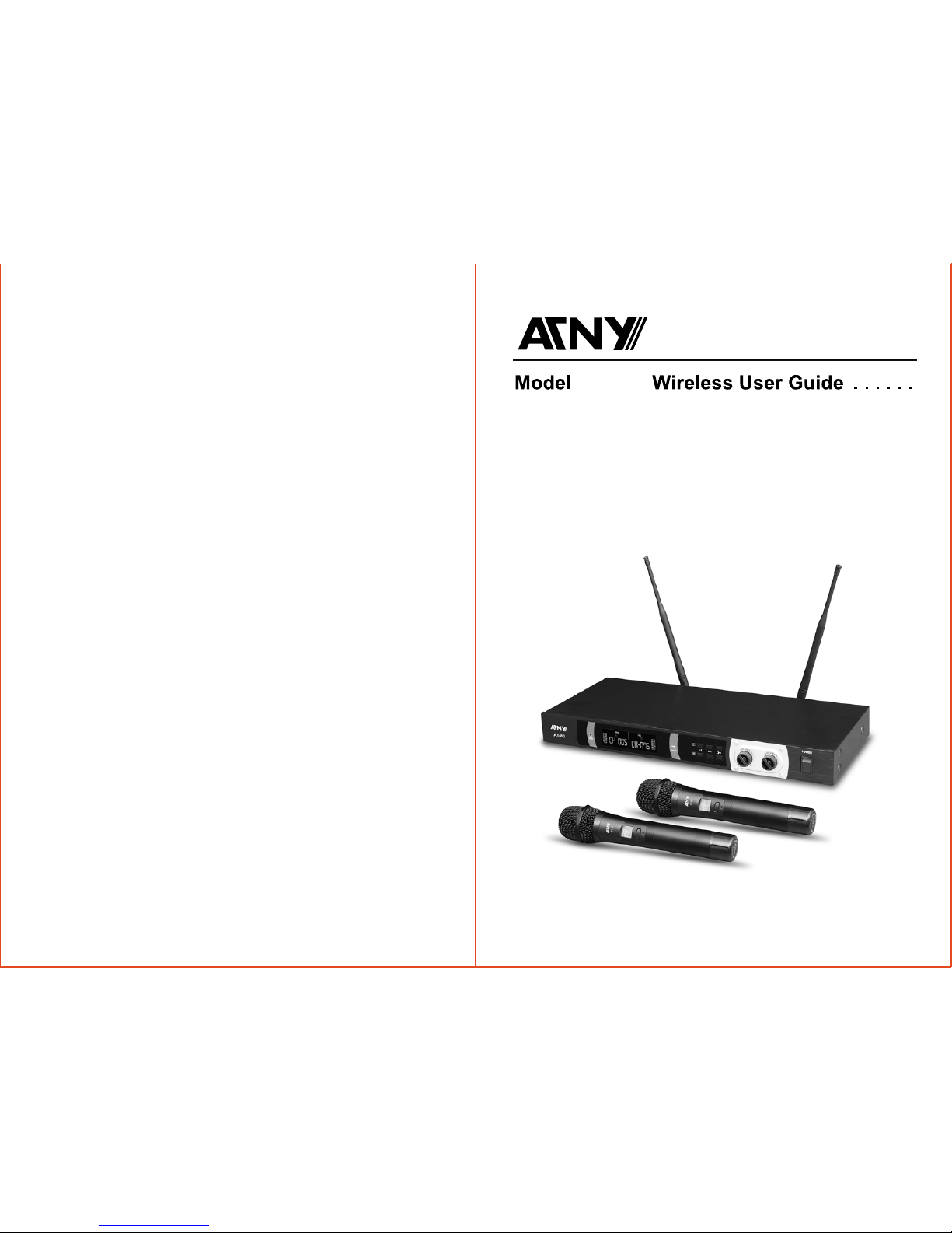
AT-80
UHF Wireless Microphone System
Address: 6005 7th Ave Brooklyn, NY 11220
TEL: 1-866-828-6886
www.atnypro.com
ATNY INTERNATIONAL INC.
Page 2

1
English
2
System Features
Wireless Receiver
TABLE OF CONTENTS
INTRODUCTION
Thank you for choosing the wireless system, we know you will be very pleased with its performance and
features. The wireless system is a professional 2-channel UHF PLL wireless system which offers the
clearest, most natural sound available in wireless today. The wireless system delivers eight discrete
channels on selected frequency bands for interference-free performance in any application or locale. It also
features ATNY proprietary companding and low noise circuit for an industry best 105dB dynamic range.
USING THIS MANUAL
This booklet provides information regarding the use of the wireless systems: wireless microphone receiver,
Handheld microphone transmitter and the bodypack microphone transmitter. It includes a description of
features and a step-by-step guide to operation of the unit. This manual should answer any questions you may
have about the operation and servicing of your wireless system.
TABLE OF CONTENTS .............................................................................................................................. 1
INTRODUCTION ........................................................................................................................................ 1
USING THIS MANUAL ............................................................................................................................... 1
SYSTEM FEATURES ................................................................................................................................. 2
RECEIVER OPERATION INSTRUCTIONS ............................................................................................... 3
HANDHELD TRANSMITTER ........................................................................................................................... 4
BODYPACK TRANSMITTER...................................................................................................................... 5
SYSTEM OPERATION .............................................................................................................................. 6
SPECIFICATIONS ..................................................................................................................................... 9
CAUTIONS AND TROUBLESHOOTING ................................................................................................. 10
Unsurpassed state-of-the-art PLL UHF performance with 105dB dynamic range and operation up to 500
feet line-of sight
Two complete and independent wireless receivers with 100 user-selectable UHF frequencies for simultane-
ous operation of two transmitters
AUTO-SCAN for easily locating clear channels and Auto-Sync Channel IR download feature which sends
selected Channel information to transmitter via IR sender for easy frequency synchronization
Sophisticated IF filtering for simultaneous operation of multiple systems in the same location
Front panel touch control buttons and user-friendly LCD configuration menus
Front panel backlit LCD display indicates selected Channel, RF signal strength meter; Audio Output
Volume level; Separate audio LED bar graph display providing instantaneous audio level status easily seen
from a distance
Back panel Balanced XLR Mic level and Unbalanced ¼” SUM Line level audio output jacks, squelch
control, RF BNC connectors for dual removable ½ wave antennas, and DC power input jack supply
Externally powered (adapter included)
Rugged all-metal housing— 1U rack mountable with supplied rack ears
Works with any two combinations of available instrument, handheld and lavalier UHF transmitters
•
•
•
•
•
•
•
•
•
•
Choice of transmitters: HT or BT, all with 100 easily selectable channels: manually with up/down buttons on
units or via IR Sync download of selected channel for easy synchronization with receiver
HT Handheld transmitter features a sleek, durable all-metal housing; power Off/On switch; internal antenna
system; and superior neodymium cartridge for clear, powerful audio, maximum feedback rejection, and
minimal handling noise
BT bodypack transmitter (choice of three versions: LT, LT/HM, or GT) features road worthy all-metal case;
power Off/On switch; flexible external antenna rod; and mini locking connector for lapel (LT), Headmic
(LT/HM), or instrument (GT) applications
HT and BT transmitters feature LCD displays indicating selected Channel, and Battery level status; and
operation with two AA batteries (alkaline or rechargeable NiMH) for longest reliable, economical battery life
•
•
•
•
Handheld/Bodypack Microphone Transmitter
Page 3
3
EnglishEnglish
4
Quick User Controls Guide
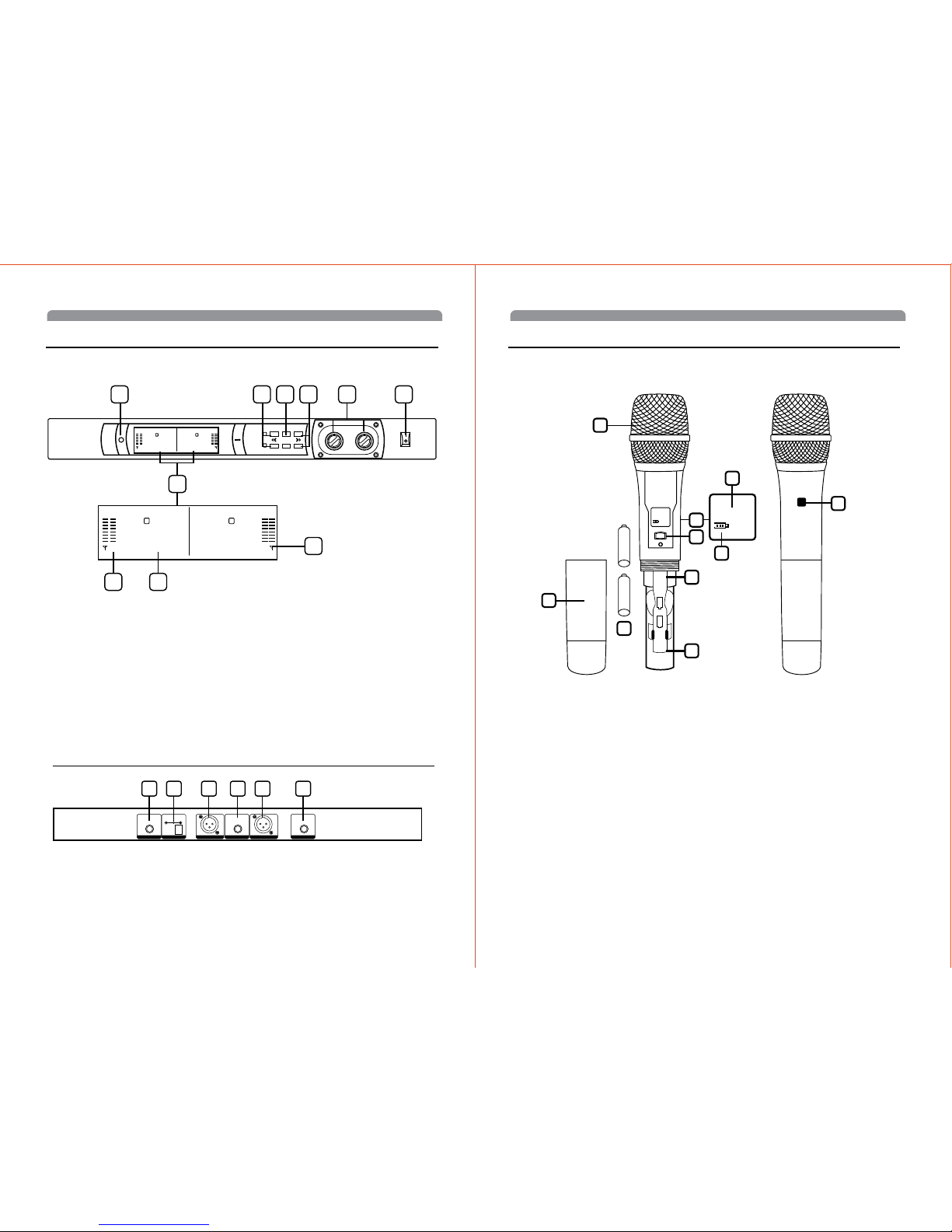
1. IR Infrared LED transmitter window for linking the RX to the TX for frequency download
2. LCD DISPLAYS For indication of frequency, AF/RF signal strength indica tor 1-8 bars, and Battery
meter indica tor 1-3 bars
3. RF SIGNAL METER Indicates received signalstrength level from 1-8 bars, (full 8 bars shows strongest
incoming RF signal)
4. AF SIGNAL METER Indicates received signalstrength level from 1-8 bars, (full 8 bars shows strongest
output AF signal)
5. FREQUENCY Indicates selected frequency
6. DOWN BUTTON To change the receiver channel down by one step at a time, lock/unlock the
setting(hold 5 seconds)
7. SET BUTTON To scroll through the LCD menu and set the selected program/function
8. UP BUTTON To change the receiver channel down by one step at a time, start the sync function
9. VOLUME LEVEL KONB To change the receiver LINE output VOL level
10. POWER BUTTON Press for one second to turn both receivers ON-OFF
Receiver: Back View
1. RF CONNECTORS A/B Antenna jacks for RF reception
2. UNBALANCED AUDIO OUT Volume Level audio output for one receiver—adjustable LINE level
3. BALANCED MIC OUT Audio output connection for each receiver—fixed mic level, not adjustable
4. DC INPUT JACK For using supplied external DC adapter to power the receivers
AF OUTPUT
UNBALANCED
AF OUTPUT
UNBALANCED
334 21 1
MIX
DC INPUT
12-15V/800mA
ANT.B ANT.A
POWER
set
CH-005 CH-075
L
A B
R
AF AF
syn c control
CH-005 CH-075
A B
AF AF
3
4 5
2
1 8 7 6 9 10
L
Quick User Controls Guide
Receiver: Back View
3
6
8
2
1
5
5
9
7
10
+
+
CH-005
CH-005
1. BATTERY COVER Unscrew to insert two AA alkaline batteries
2. MIC BALL Windscreen/dust cover
3. LCD DISPLAY For indication of channel, battery mete
4. CHANNEL Indicates selected channel
5. BATTERY METER Indicates battery status (3 bars=100%, 1 bar=33.3%). Change batteries when flashing
6. POWER ON/OFF SWITCH Press power switch to turn ON-OFF
7. INTERNAL ANTENNA Built-in antenna
8. IR RECEPTOR SENSOR/WINDOW Infrared LED sensor for linking the TX to the RX during IR frequency
download.
9. BATTERY COMPARTMENT
10. TWO AA ALKALINE BATTERIES
Page 4
5
EnglishEnglish
6
System Operation
Quick User Controls Guide
Bodypack Transmitter
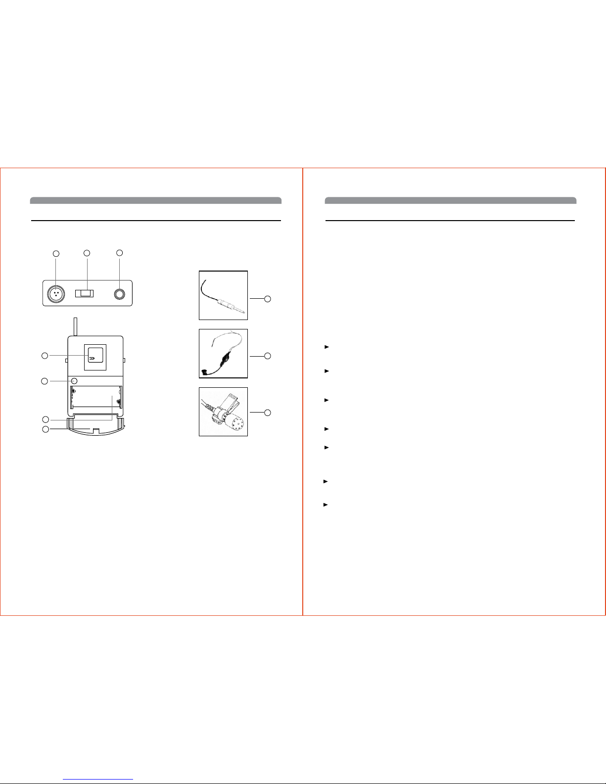
1. Audio input socket(3pin), can be connected to various
kind of lavalier microphone or head-set microphone.
2. Power switch: turn on/off the transmitter power supply.
3. Transmit antenna.
4. LCD screen.
5. Infrared frequency window
6. Cell box, for 2 x 1.5V battery
7. Battery cover
8. INSTRUMENT CORD GT cable—connects instrument’s audio output to TX input jack
9. HEADMIC Headworn microphone (choice of models)—connects to transmitter input jack
10. LAVALIER MIC Lavalier (lapel) microphone (choice of models)—connects to transmitter input jack
1
2
5
6
7
8
9
10
3
4
CH-005
1. Key functions and operations
1. Press the middle button "SET" can select menu and
confirm your Settings
2. Press "▲" "▼" button to select or adjust the current menu,
and then "SET" key set to store your settings.
3.Long press "▲" "▼" key to select frequency and channel
quickly
Receiver
OPERATION MENU OF LCD
Volume
Adjust the volume knobs the add or reduce the volume level.
Note: Do not mount the receiver on a rack directly
above an amplifier or other source of high heat. This could
degrade the performance of. Always ensure adequate airflow
and heat dissipation in any rack configuration.
Installing Antennas
Install antennas by connecting the two Antennas included
with your system onto the two RF Connectors located on
the back of the receiver. The two antennas must be installed.
The optimal positions of the antennas are 45° from the
receiver and 90° from each other. For maximum range, it is
always best to maintain a line-of-sight (no obstructions)
between the receiver antennas and the transmitter at all
times whenever possible.
Powering the Receivers
To power the receivers, plug the supplied AC/DC Power
Supply adapter into the DC Input Jack on the back of the
receivers, then plug the adapter into an AC outlet.
Note: Any 12-16VDC power source with 800mA minimum
capacity can also be used. To turn on, press down the Power
Button The LCD Display will light up. To turn off, press the
Power button up. The LCD will display “OFF” then the
backlight will turn off indicating the receivers are off.
Connect either the ¼” Unbalanced SUM Line Out or ¼”
each Unbalanced Line Out or each XLR Balanced Mic
Outs to your mixing board, effect, or amplifier inputs (See
Connecting the Audio Outputs section).
Connecting the Audio Outputs
The receiver has one Unbalanced Audio SUM Out
adjustable line level audio output and two Balanced XLR Mic
Out fixed level jacks and each works independently per
channel. The Unbalanced Audio Out is controlled by volume
knobs. For unbalanced output, plug a ¼” mono (Tip/Sleeve)
audio cable into the Unbalanced Audio Out jack and plug the
other end into your mixing board or amplifier. When using the
instrument transmitter system, connect the Unbalanced
Audio SUM Out directly to your instrument amp or preamp. At
maximum receiver volume setting, as indicated by the
Volume display, the system output is approximately +4dB
higher than a direct cord-to-amp connection.
B. Getting into the operating menu
Display
Press the SET button to get into the standard display into the
operating menu. 2-3 seconds later, CHANNL or FRE QU
appears.
CHANNEL DISPLAY
Press the SET button and select the CHANNEL mode. This
menu shows the current channel.
Press the ▲/▼ button can change the channel, If you hold
down a bu
tton, the display cycles continuously. The “fast search”
function allows you to get fast and easily to your desired
setting.
The new setting flashes on the display until it is stored, or the
transmitter will work at the previous channel.
2.LCD display
A.Infrared frequency
Press the “SET” button when the LCD display “IR-TX”,2-3
seconds later, transmitting the infrared frequency to the
transmitter.
FREQUENT DISPLAY
Press the SET button and select the FRE QU mode. This
menu shows the current frequency.
Press the ▲/▼ button to adjust the setting. By briefly
pressing the ▲/▼ buttons, the display jumps either forwards
or backw-ards to the
next settin continuously. (Illustration:
To
display whi-ch menu depend on the previous SET status.)
Press the ▲/▼ button can change the frequency, If you hold
down a button, the display cycles continuously, The
“fastsearch”function allo
ws you to get fast and easily to your
desired setting. The new setting
flashes on the display until it
to stored,
or the tran-smitter will work at the previous
frequency.
Press the SET button to store the setting, orthe screen
flashing after 2-3 seconds indicating that the settings are not
available, the transmitter still work at previous setting.
Page 5

7
EnglishEnglish
8
Note: Both receivers’ output will be mixed together as per the
individual receivers’ volume settings controlled by volume
knobs. If separate signals are required for each instrument
then the XLR outputs must be used, however, note they are
not line level or adjustable. The SUM out is best utilized for
switching between separate transmitters during performance
with only one audio signal
at a time fed to the instrument amplifier. For balanced output,
plug an audio cable with an XLR connector into the XLR
Balanced Mic Out socket for each receiver and plug the other
end into your mixing board or amplifier inputs accordingly As
when making any connection, make sure the amplifier or
mixing board volume is at the
minimum level before plugging in the receiver to avoid
possible sound system damage.
Your receiver is now operational and ready to use. Once you
have completed the above steps, proceed to the following
instructions for the handheld or instrument transmitter.
Note: Only one transmitter can be used with one receiver. It
is not possible to use two transmitters on the same frequency
and mix the output of these transmitters into one wireless
receiver. However, as this is a two receiver unit, two transmitters on separate frequencies can be utilized, one with each
receiver.
Setting up the Transmitter
The BT bodypack requires two AA size batteries to operate.
To install the batteries into the battery compartment, lift the
Battery Compartment Door by grabbing the two
spring-loaded locking tabs and pull out, exposing the Battery
Compartment. Insert two fresh AA batteries according to the
correct polarity as indicated on the transmitter body. Close
the battery cover, ensuring the cover is snapped shut. Fresh
alkaline batteries can last provide up to 8-10 hours of
operation, but in order to ensure optimum performance it is
recommended that the batteries be replaced after 6-8 hours
of use or as indicated necessary by the flashing Battery
Meter “BATT” Icon.
Connecting Input Audio Source
Use the Audio Input 3 pin三 locking mini jack for connecting
the audio input cord from lapel mic (LT), Headmic (LT/HM), or
instrument (GT), depending on which version transmitter is
being used. Secure the connection to the cable by lining up
the slot of the mini connector and turning the ring to securely
lock in.
Powering the Transmitter On/Off
To turn on the transmitter, slide the Power Off/On Switch .
The LCD backlight will light up. The unit is now on. After ten
seconds the backlight will automatically turn off. The
Channel) and Battery Meter remain on in normal operation.
As many of the LCD battery levels should stay lit as possible,
indicating usable battery strength. As the batteries weaken,
fewer of the level indicators stay lit until only one bar shows,
which will then flash to warn that the batteries are now too
low andshould be replaced as soon as possible. To preserve
battery life, turn the transmitter off when not in use. To turn
the transmitter off, slide the Off/On switch and then “OFF”.
The LCD will display “OFF”, no LCD or backlight is lit up and
the unit will be off. At Power Off the transmitter will store the
last settings entered and re-display
them at the next power on where it can be reprogrammed to
any new Channel or Volume level at the first time of use or
anytime later. The factory default setting for Volume 0dB is
same for all transmitters. These settings are optimal for most
applications.
Setting up the Transmitter
The requires two AA size batteries to operate. To install the
batteries onto the battery compartment, unscrew the Battery
Compartment Cover by turning counterclockwise until
loose and slide down
the cover, exposing the Battery Compartment . Insert two
fresh AA batteries according to the correct polarity as
indicated on the transmitter body. Screw the battery cover
back onto the microphone, making sure it is securely
tightened. Fresh alkaline batteries can provide up to 8-10
hours of operation, but in order to ensure optimal
performance it is recommended that the batteries be
replaced after 6-8 hours of use or as indicated to be
necessary by the flashing Battery “BATT” Meter Icon.
Powering the Transmitter On/Off
To turn on the transmitter, slide the Power On/Off Switch to
the “ON” position. The LCD backlight will light up, indicating
the unit is now on. After ten seconds the backlight will
automatically turn off to conserve battery life. The Channel
and Battery Meter indicator icons stay on for normal
operation.
As many of the LCD battery levels should stay lit as possible,
as they indicate usable battery strength. As the batteries
weaken, fewer of the level indicators will stay lit until only one
bar shows, which will then flash to warn that the batteries are
now too low and should be replaced as soon as possible with
fresh ones.
To preserve battery life, turn the transmitter off when not in
use. To turn the transmitter off, slide the power on/off switch
to the “OFF” position. The LCD will display “OFF,” no LCD or
backlight is lit up and the unit will be off.
At Power Off the transmitter will store the last settings
entered and re-display them at the next power on where it
can be reprogrammed to any new frequency at the first time
of use or anytime later.
Programming the Transmitter to the Selected channel
The transmitter can be programmed to the same channel as
selected for the receiver, either via automatic synchronization
using the IR Sync function or manually on the transmitter
itself.
IR Sync Programming:
Use the wireless IR LED Receptor Sensor to download
pre-programmed channel from the receiver. Start programming
by holding the IR LED Receptor about 6-12” from the
receiver’s IR LED Window , then press the IR Sync Button
on the receiver to be used, the IR LED will light up red and
stay for about five seconds. This indicates IR transmission is
in progress and IR data is transferring during this period.
Upon successful data transfer (usually in about three
seconds) the IR LED stops and the transmitter’s backlight will
light up and the transmitter will transmit a radio signal on the
same frequency as the receiver. The Signal Strength on the
receiver’s LCD display will then light up, indicating that the IR
link is completed.
Note: If procedure is not done correctly during the five
seconds of active data transfer, the receiver and the transmitter do not link and transmitter’s previous programmed
channel remains unchanged.
The IR link is infrared light and thus works best when this
data transfer is accomplished in a light-shielded or darker
environment. It may not be successful in a brightly lit area. If
the transfer fails, repeat the procedure in a darker location or
somehow shield the link from outside light to successfully
program the transmitter with the pre-programmed group and
channel info from the receiver.
Operating the Handheld Transmitter
During normal operation with the unit powered ON, the
transmitter power level can be changed by sliding the On/Off
switch to the “ON” position and the microphone is now ready
to use. The receiver’s RF Signal Meter should now be on,
indicating a received signal from the transmitter. Adjust the
volume of the receiver per Connecting the Audio Output
section above.
Note: Avoid acoustic feedback (howling or screeching) by
taking care in selecting PA volume, transmitter location and
speaker placement.
The RF Signal meter on the receiver’s LCD display should be
“ON” in normal operation.
Programming the Transmitter to the Selected Channel
The transmitter can be programmed to the same channel as
selected for the receiver, either via automatic synchronization
using the IR Sync function or manually on the transmitter
itself.
IR Sync Programming:
Use the wireless IR LED Receptor Sensor to download
pre-programmed frequency from the receiver. Start programming by holding the IR LED Receptor about 6-12” from the
receiver’s IR LED Window , then press the IR Sync Button
on the receiver to be used, the IR LED will light up red and
stay for about five seconds. This indicates IR transmission is
in progress and IR data is transferring during this period.
Upon successful data transfer (usually in about three
seconds) the IR LED stops and the transmitter’s backlight will
light up and the transmitter will transmit a radio signal on the
same frequency as the receiver. The Signal Strength on the
receiver’s LCD display will then light up, indicating that the IR
link is completed.
Note: If procedure is not done correctly during the five
seconds of active data transfer, the receiver and the transmitter do not link and transmitter’s previous programmed
channel remains unchanged.
The IR link is infrared light and thus works best when this
data transfer is accomplished in a light-shielded or darker
environment. It may not be successful in a brightly lit area. If
the transfer fails, repeat the procedure in a darker location or
somehow shield the link from outside light to successfully
program the transmitter with the pre-programmed group and
channel info from the receiver.
Handheld Microphone Transmitter
Bodypack Transmitter
Page 6

9
EnglishEnglish
10
Specifications
Harmonic and Spurious Emission
Audio Input Levels
Input Impedance
Controls
Input Connector
LCD Display
Antenna Type
Battery Type
Battery Life
Feedback
Avoid acoustic feedback (howling or screeching) by taking care in selecting PA volume, transmitter location and speaker
placement. Please also note the pickup pattern characteristics of the microphone selected. Unidirectional mics are more
resistant to feedback. However, they pick up sound sources best that are directly in front of the mic. Also mics that are farther
from the sound source require more acoustic gain and thus are also more prone to feed back than close-source mics such as
handheld.
No or Low Audio
If you are not getting audio through the system, carefully re-check all setups. Especially note that the receiver and transmitter
must be set to operate on the same RF channel. The receiver’s Unbalanced Line Level Out is adjustable so make sure the
Volume is set properly. RF Interference and Finding Open Channels If you encounter slight receiving interference when the
transmitter is far from the receiver (from other than an operating TV station on the same frequency), If receiving interference on
a selected channel with the transmitter off, you must reprogram the receiver and transmitter to a different channel.
See: Selecting the Receiver Volume Level / Channel Programming the HT/BT to the Selected Channel
To reprogram, you must first find an open channel. To do this, follow the operating procedure outlined in Selecting the Receiver
Volume Level / Channel. With the associated transmitter off, scroll through the groups/channels to find one that shows no
received signal on the receiver’s RF Signal Meter (no bars). Also, there must be no bars either on each of the three immediately
adjacent channels both above and below the selected channel for optimum interference-free operation (i.e. in a field of seven
adjacent channel total—with the channel used in the middle). If operating multiple Series systems simultaneously, repeat this
procedure with every new channel being selected, with previously tuned systems all on, both transmitters and receivers.
Please note that wireless frequencies are shared with other radio services. According to FCC regulations, wireless microphone
operations are unprotected from interference from other licensed operations in the band. If any interference is received by any
Government or non-government operation, the wireless microphone must cease operation or change frequencies. The above
statement is valid only for use in the U.S.A.
Note: More bars in the Received Signal icon indicate good signal strength in operation with the transmitter on, but more than 1
bar showing with the transmitter off also indicates the presence of likely RF interfering signals at that location. If this happens,
select a different channel. One bar or less is ideal for interference-free operation.
-50dBc normal
(Lapel/Lavaliere—LT)/ (Headmic LT/HM)/ (Instrument—GT)
5kΩ (Lav Mic), 500 kΩ (Instr.)
Power OFF/ON
Mini 3 pins with locking nut
Channels Battery Levels
External fixed
2 x AA alkaline batteries operation
8-10 Hours typical
BODYPACK TRANSMITTER SPECIFICATIONS
Cautions and Troubleshooting
Operating Frequency Range
Freq. Synthesized
PLL System Frequency Stability
Frequency Response
Dynamic Range
Harmonic Distortion
Modulation
Operating Range
SYSTEM OVERALL SPECIFICATIONS
Receiver System
Selectivity
Image Rejection
Sensitivity
Spurious Rejection
Mute Threshold
Controls
LCD Display
AF/PEAK LED Display
Audio Output Level
Output Impedance
Power Requirement
Antennas
Housing Construction
RECEIVER SPECIFICATIONS
RF Output Power
Harmonic and Spurious Emission
Audio Input Levels
Impedance
Controls
LCD Display
Antenna Type
Battery Type
Battery Life
Housing Construction
HANDHELD TRANSMITTER SPECIFICATIONS
614.00-698.00 MHz according to the final product
(100 channels switchable) 250 kHz/step
<0.005%
30Hz-18kHz +/-3dB
105dB
<0.5%
FM (F3E) +/-25kHz normal, +/-75kHz max
40m typical
Dual conversion Super Heterodyne
60dB, normal +/-75kHz offset
-70dB, minimum
-107dBm, norma
65dB, normal
-65dBm to -95dBm (adjustable)
UP/DOWN selects, SET, IR Sync, Power ON/OFF buttons
Dual backlight LCD panels indicating selected Frequency, Received RF levels
8-segment LED tree indicating received audio levels from transmitter
Unbalanced output: LINE Level output adjustable
Balanced output: MIC level output fixed
Balanced and unbalanced: 600 Ω
12-16VDC/0.8A
Dual TNC right angle
Metal
+10dBm
-50dBc normal
24mV for +/- 25 KHz deviation
0.6 kΩ
Power ON/OFF
Channel Battery Levels
Integral
2 x AA alkaline batteries operation
8-10 hours typical
Metal
Specifications subject to change at any time without prior notice for purposes of product improvement
 Loading...