

ATN ThOR-HD 384 9 - 36x, ThOR-HD 640 1.5 - 15x, ThOR-HD 384 1.25 - 5x, ThOR-HD 384 4.5 - 18x, ThOR-HD 640 2.5 - 25x User Manual
...Page 1
ThOR-HD Series
THERMAL SMART HD RIFLESCOPE
MANUAL
THOR-HD USER’S GUIDE (REV. 4, AUGUST, 2017)
AMERICAN
TECHNOLOGIES
NETWORK
CORP.
Page 2
2
THIS PRODUCT CONTAINS NATURAL RUBBER LATEX, WHICH MAY CAUSE ALLERGIC REACTIONS
CAUTION!
The instructions in this manual are for informational use only and subject to change without notice,
this manual is not to be construed as a commitment by ATN Corp.
ATN Corp. assumes no responsibility or liability for any errors or inaccuracies that may appear in this book.
©2017 ATN Corp. All rights reserved.
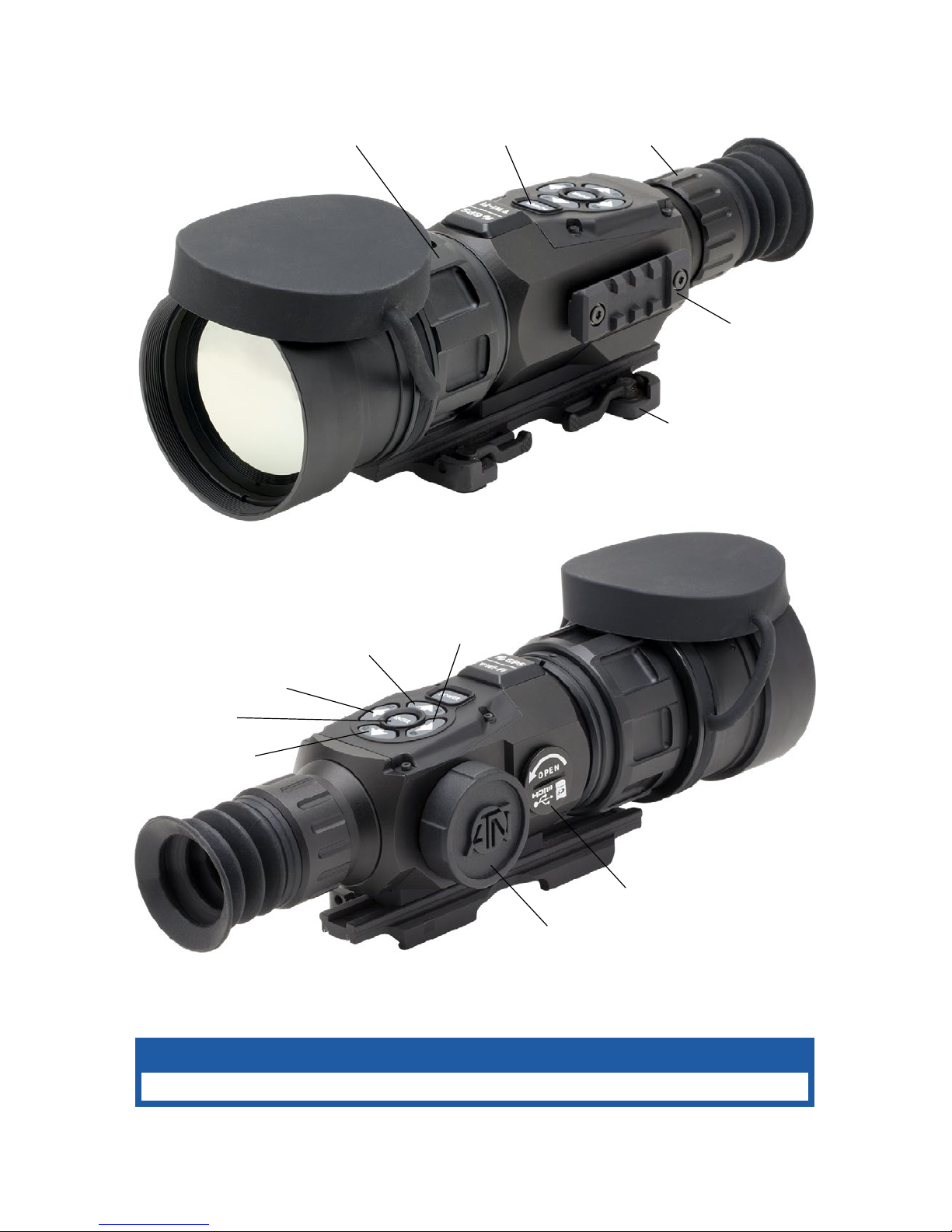
PICATINNY RAIL
DIOPTER
ADJUSTMENT RING
MOUNTING SYSTEM
POWER BUTTON
FOCUS
ADJUSTMENT RING
BATTERY
HOUSING CAP
START/STOP
VIDEO RECORDING
ENTER BUTTON
TAKE A PICTURE
ZOOM IN
ZOOM OUT
MICROSD,
MICRO HDMI
& MICRO USB
Page 3

3
TABLE OF CONTENTS
FEATURES ....................................4
APPLICATION .................................4
SPECIFICATIONS ..............................5
PREPARING THE DEVICE .......................7
Unpacking .................................7
Installation of batteries ........................7
MicroSD, USB and HDMI ports .................7
Firmware update ............................8
ON/OFF ...................................9
Using keypad ...............................9
Focusing ..................................9
Mounting your scope ........................10
Compass calibration ........................10
INTERFACE ..................................11
Homescreen ..............................11
Main operations ............................12
Shortcut carousel ..........................13
Using System Settings .......................14
FUNCTIONS ..................................16
Photo modes ..............................16
Recoil Activated video .......................17
Rangefinder ...............................19
Zeroing ..................................21
Ballistic Calculator ..........................22
How to perform a NUC .......................26
Pixel Correction Procedure ...................26
Reticle style adjustment ......................27
SYSTEM SETTINGS .......................... 28
Thermal ..................................28
Photo/Video ...............................28
Display ...................................29
Profiles/Zero ..............................29
Settings ..................................30
SERVICING ..................................31
Warnings and cautions ......................31
MOBILE APPLICATIONS .......................31
Page 4
4
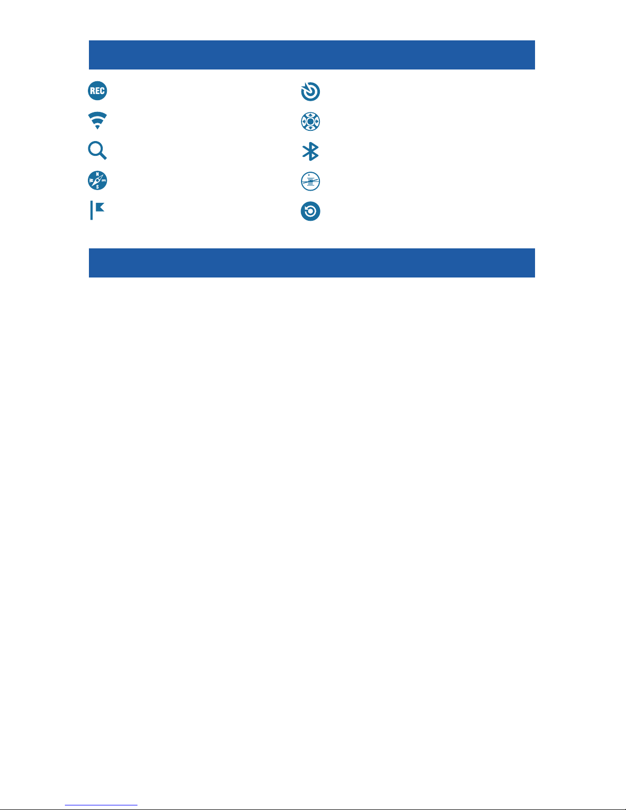
FEATURES
RECORD HD VIDEO BALLISTIC CALCULATOR
WiFi OBSIDIAN USER INTERFACE
SMOOTH ZOOM BLUETOOTH
E-COMPASS 3D GYROSCOPE
SMART RANGE FINDER
RECOIL ACTIVATED VIDEO (RAV)
APPLICATION
The most technologically advanced line of thermal rifle scopes on the
market, bar none! The all new Obsidian “T” II Thermal Core is at the heart of
all ATN systems. This technology helped ATN to continue to make bigger and
better updates to its award winning thermal product line.
Record videos and photos onto a microSD card. Never again forget to
record that perfect shot with ATN’s patented RAV (Recoil Activated Video).
Use ATN’s Smart Range Finder to quickly range in on your target and allow
the ballistic calculator to make instantaneous corrections to your POI (Point
of Interest) on the fly. Plus, take advantage of the additional features and
sensors packed into these incredible systems, such as; Smooth Zoom, built
in Wi-Fi, Bluetooth, 3D Gyroscope, 3D Accelerometer and 3D Magnetometer.
Page 5

5
SPECIFICATIONS
ThOR-HD 384
1.25 - 5x
ThOR-HD 384
2 - 8x
ThOR-HD 384
4.5 - 18x
ThOR-HD 384
9 - 36x
ThOR-HD 640
1 - 10x
ThOR-HD 640
1.5 - 15x
ThOR-HD 640
2.5 - 25x
ThOR-HD 640
5 - 50x
Item #
TIWSTH381A TIWSTH382A TIWSTH384A TIWSTH389A TIWSTH641A TIWSTH642A TIWSTH643A TIWSTH645A
Sensor
384×288 640×480
Magnification
1.25 - 5x 2 – 8× 4.5 – 18× 9 – 36× 1 – 10× 1.5 – 15× 2.5 – 25× 5 – 50×
Angle of view
16×12.5 12×9.5 6×4.7 3×2.4 32×25 24×19 12.5×9.7 6×4.7
Objective lens focal length
19 mm 25 mm 50 mm 100 mm 19 mm 25 mm 50 mm 100 mm
Micro Display
HD Display
Core
ATN Obsidian “T” II
Eye relief
65 mm
Waterproof rating / IP rating
Weather resistant
Video Record Resolution
1280×960 @ 30 fps
Microphone
Yes
MicroSD card
Up to 64 GB
Micro USB
Yes
Micro HDMI
Yes
WiFi (Streaming, Gallery,
& Controls)
iOS & Android
Bluetooth
4.1
GPS (Geotagging, Elevation, etc.)
Yes
Page 6

6
ThOR-HD 384
1.25 - 5x
ThOR-HD 384
2 - 8x
ThOR-HD 384
4.5 - 18x
ThOR-HD 384
9 - 36x
ThOR-HD 640
1 - 10x
ThOR-HD 640
1.5 - 15x
ThOR-HD 640
2.5 - 25x
ThOR-HD 640
5 - 50x
3D Gyroscope
Yes, GS7
3D Accelerometer
Yes
3D Magnetometer
Yes
Range Finder
Yes
Ballistic Calculator
Yes
RAV (Recoil Activated Video)
Yes
Electronic Compass
Yes
Smooth Zoom
Yes
Reticles
Multiple Patterns & Color Options
Mount
Two fixing
screws mount
Picatinny Quick Release Mount, Interchangeable
Compatible mounts
A.R.M.S.® #17® (single lever), A.R.M.S.® #35® (double lever), LaRue LT270, American Defense (AD-170)
Battery life (Li-ion)
8 hr
Battery type
(4) AA (Lithium Recommended)
Dimensions
6.85”×3.16”×3.14”
174×80.26×80 mm
8.81”× 3 .16”×3.14”
224×80.26×80 mm
10.67”×3.97”×3.47”
271×101×8 8 mm
6.85”×3.16”×3.14”
174×80.26×80 mm
8.81” x 3.16” x 3.14”
224×80.26×80 mm
10.67”×3.97”×3.47”
271×101×8 8 mm
Weight
1.55 lb / 0.68 kg 1.85 lb / 0.84 kg 2.75 lb / 1.24 kg 1.55 lb / 0.68 kg 1.85 lb / 0.84 kg 2.75 lb / 1.24 kg
Warranty
3 years
Human Detection Range
625 800 1500 2500 625 800 1500 2500
Human Recognition Range
280 400 600 1100 280 400 600 1100
Human Identification Range
170 250 360 600 170 250 360 600
* ATN reserves the right to change the above specifications at any time without notice
Page 7
7
PREPARING THE DEVICE
UNPACKING
The following steps must be performed prior to use:
1. Open packaging box, remove ThOR-HD and check the contents.
• ATN Help Card
• ATN Thor- HD
• Battery Lifetime Information and Power Kit Card
• FB Group and ATN Forum Card
• Firmware Update and Review Card
• Black Nylon Case
• Thor HD Manual
• Thor HD Quick Start Guide Card
2. Make sure that nothing is missing.
3. Inspect the device for damage to optical surfaces, body, eyecups, opera-
tion buttons, etc.
4. Ensure that all optical surfaces are clean and ready for use.
NOTE
If any accessories are missing or broken contact ATN’s Customer Ser-
vice.
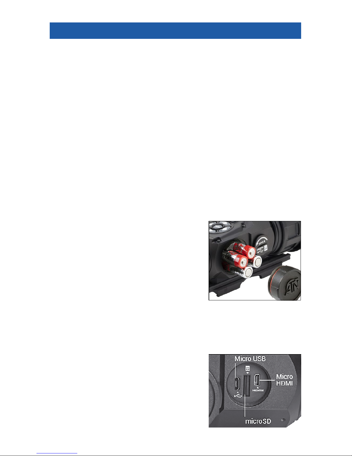
INSTALLATION OF BATTERIES
The Thor-HD will operate on four AA-type Lithium batteries.
NOTE
We highly recommend using lithium AA
batteries. They will provide much longer battery life. Use only 1.5 V batteries.
Install batteries as follows:
1. Remove the battery cap by unscrewing it
counter clockwise.
2. Insert batteries as shown.
3. Return the battery cap into the housing
socket (screw clockwise until finger tight). Make
sure that the Red O-Ring is not visible to prevent shut off issues due to recoil, but also Do not over-tighten! You want to
ensure you can unscrew the cap next time you replace batteries.
NOTE
Make sure that the device is turned off before changing source of
energy (batteries or USB in power supply mode).
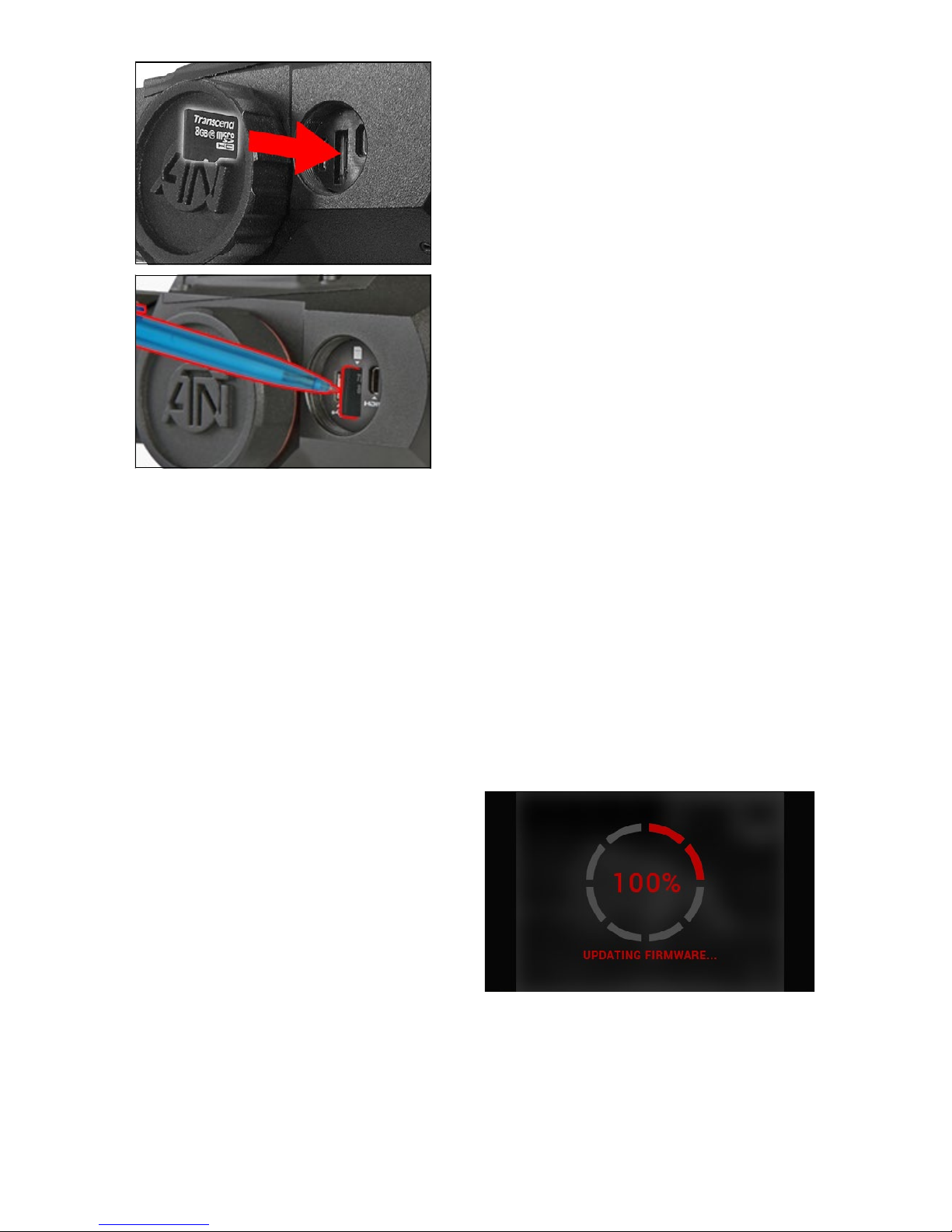
MicroSD, USB
AND HDMI PORTS
The device is equipped with microSD, micro
USB and micro HDMI ports and can be found
under the cap near the battery block (marked
with appropriate icons on the cap).
NOTE
Make sure the device is turned off before
inserting the microSD card into the slot.
Page 8
8
To Us e:
1. USB cap cover should be unscrewed
counterclockwise.
2. Format new cards before use.
3. Insert microSD card as shown.
4. To lock, insert card in the slot and
push it with a thin object (a small coin,
paperclip, toothpick, etc.).
5. Return the cap to the USB cap cover
(screw clockwise until finger tight).
NOTE
There is only one correct direction to
insert the microSD Card. Do not force
the card into the slot, as it may damage
both the scope and the card itself.
To remove the microSD Card from the
slot:
1. Push it in using the same thin object.
2. When it pops up a few millimeters, it
can be pulled with your fingers or tweezers.
NOTE
If you are going to record video, the microSD card should be a Class 10 (10
Mb/s) or faster and have capacity from 4 to 64 Gb.
FIRMWARE UPDATE
Before operating your device, update the firmware to the latest version.
To receive a notification of new firmware updates, please register your
device on our website (you’ll receive an email letting you know when the new
firmware becomes available).
To update the new firmware you will need a microSD card and batteries that
are fully charged.
NOTE
In the event of a power failure during an update. The device may crash,
corrupting its system files. It will need to be sent back to the ATN factory for
service. DO NOT USE an additional source of power during firmware update!
Update the new firmware as follows:
1. Download the ***.bin file from
https://www.atncorp.com/firmware (You
may need to create an account, if you
didn’t create it earlier) and copy to your
microSD Card — root directory.
2. Insert the card into the device.
3. Turn ON the device.
4. In the “Firmware Update” dialog
box select “Yes” to start the update.
5. When the update counter rea ches
“100%” the device will automatically restart.
6. Once the device is powered up it will enter self configuration mode.
7. After completing it will automatically restart and will be ready for use.
8. Motion Sensing platform will be configured when first turned on.
9. Once the Firmware update completes, please do a factory reset before using
the product.
10. Please remember to delete the Firmware File off of the microSD card after
all steps are completed.
Page 9
9
NOTE
If the device does not restart within 30 seconds, remove and re-insert
the batteries, and again power-up the device. Once the device has been
updated you will need to either format the card or delete the update file
manually. In the event you do not perform the previous actions, the system
will ask you if you wish to update the device every time you turn it on.
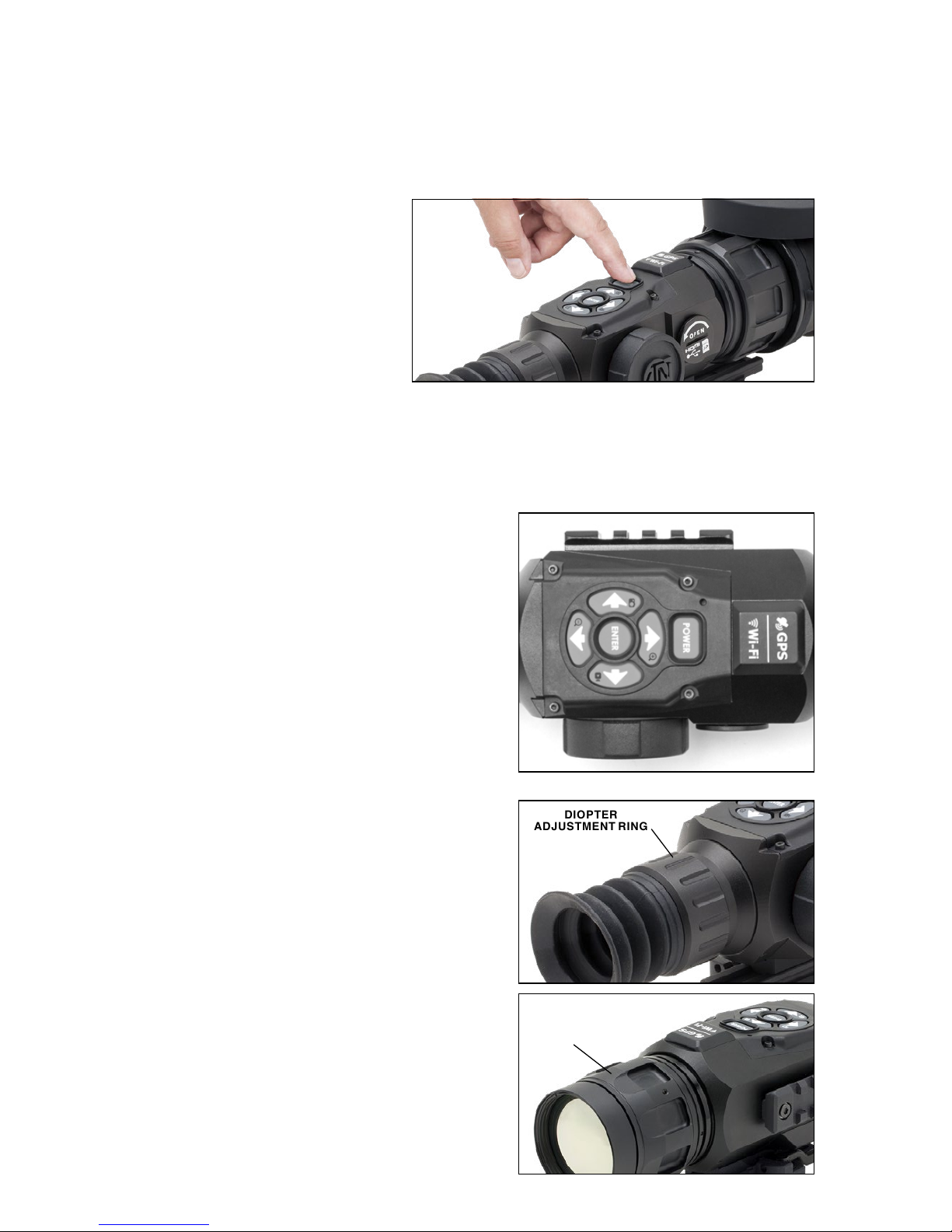
ON/OFF
To TURN ON the device,
press and hold the POWER
Button until you see the ATN
splash screen.
To TURN OFF the device,
press and hold the POWER
Button until the “Shut down
the device?” appears in the
dialog box. Choose “Yes” to turn off the unit.
NOTE
Upon startup you must perform a NUC. Please refer to page 26 to learn
how to perform the NUC process correctly.
USING KEYPAD
The KEYPAD is programmed to be used
in two different ways:
• Short and Quick Taps — used for most
functions and to get around the menu;
• Press and Hold — designed to be
used in the following situations — ON/
OFF, ZOOM and SHORTCUT MENU.
NOTE
Using LEFT or RIGHT buttons in the
Menu will allow you to quickly choose
Exit Shortcut from any position.
FOCUSING
DIOPTER ADJUSTMENT
Look through the eyepiece, focusing on
the reticle on the screen, and rotate the
Diopter Adjustment Ring until optimal
sharpness is achieved. Do not take the
rubber cap off the objective lens.
NOTE
You should not have to re-adjust the
Diopter Adjustment unless another
user, with different vision needs, uses
the scope.
FOCUS ADJUSTMENT
Remove the cap from the objective lens
and rotate the focus adjustment ring, as
necessary, to achieve the proper focus at
various distances.
DIOPTER
ADJUSTMENT RING
FOCUS
ADJUSTMENT
RING
Page 10
10
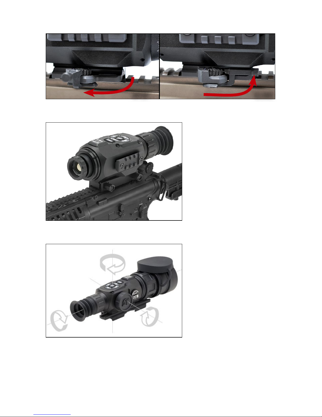
MOUNTING YOUR SCOPE
OPEN
CLOSE
Secure the ThOR-HD to your Picatinny Rail using the Quick Release Mount
as shown above. However, the ThOR-HD 384 1.25-5x has a different mount —
with two fixing screws.
1. Slightly loosen the fixing
screws on the 7/8˝ weaver
mount built into the scope.
2. Place the scope on the
weaver rail of the firearm.
3. Tighten the fixing screws.
NOTE
Fixing screws may need
to be tightened after continuous shooting. ATN recommends using “Loctite”
to ensure screws do not
loosen up during shooting.
COMPASS CALIBRATION
When the compass needs
to be calibrated, the word
“CAL” appears instead of
the Compass Scale. To calibrate, rotate the three axis
points as pictured on the left,
on the device.
NOTE
After calibrating the device, please remember that
the compass will work best
when holding the ThOR-HD
parallel to the ground.
Other possible abbreviations:
• ERR — an error was detected, you may need to restart the device or reca-
librate the compass;
• SMF — your device is under a strong magnetic field, move away from the
source;
• UPD — your firmware needs to be updated.
Page 11
11
INTERFACE
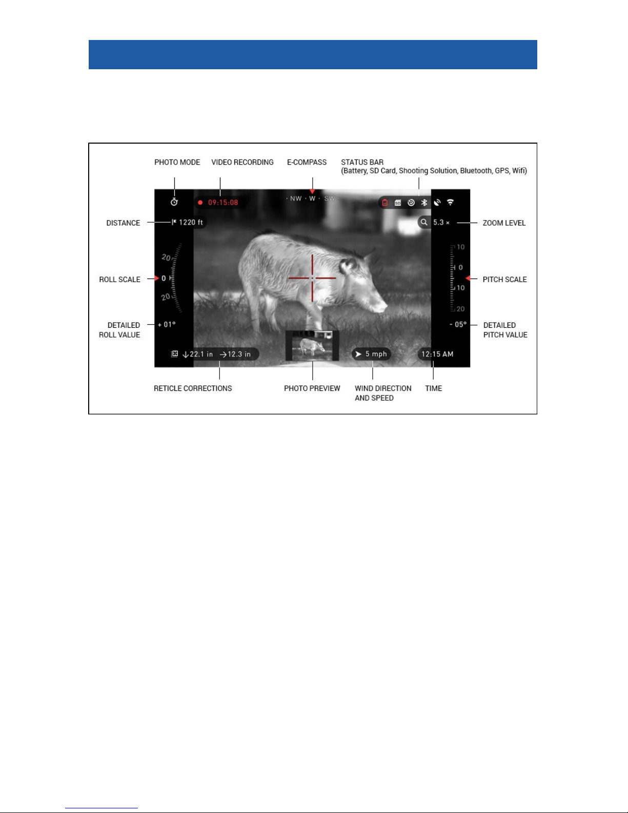
HOMESCREEN
The Homescreen will first appear when you switch on the device. It consists
of Scales, Status Bar icons and different Information Widgets.
SCALES
• The E-Compass Scale shows yaw angle based on e-Magnetometer data.
• Roll Scale shows the rifles cant based on internal 3D Gyroscope.
• Pitch Scale shows rifle inclination based on internal 3D Gyroscope.
STATUS BAR
Information displayed will only be about the current state of system.
Inactive icons become invisible, only the important information will show at
the moment:
• Battery — appears when energy level is low;
• SD Card — shows the presence of memory card;
• Ballistic Calculator, Bluetooth, GPS and WiFi — shows when a function
is enabled.
WIDGETS
There are interface elements that provide quick access to useful informa-
tion. There are several types of widgets:
• icons without value are used for mode display (Photo and Video Modes).
• only numerical value (Detailed Roll and Pitch Values).
• icons with a numerical value: Zoom, Time, Reticle Correction, Distance,
Video Recording.
• Photo Preview appears in the bottom of the Homescreen, after the photo
was taken.
Page 12

12
Display widgets can be
viewed in the System Settings.
To enter System Settings,
click on the ENTER button
from Homescreen and
access the Shortcut Carousel.
Select the wrench icon
with RIGHT or LEFT buttons
and push ENTER button
to enter the menu.
Select Display tab with
RIGHT button
and choo-
se subcategory Display Widgets with DOWN button
.
Press the ENTER button
to select the Display Widgets. Use the UP or DOWN
buttons
to change from
Extended to Minimal.
MAIN OPERATIONS
ZOOM LEVEL
1. Zoom IN and OUT by pressing and holding the UP or DOWN button
on the keypad.
2. Current Zoom Level is displayed in the Zoom widget on the Homescreen.
NOTE
You will need to configure the lens option in the pop-up window before
zooming when the device is activated for the first time.
Your reticle can be offset from the center point of the screen while using Bal-
listic Calculator. During the Zoom In Action, it will move to the center.
TAKING PHOTOS
Press the LEFT button
to TAKE A PHOTO.
Depending on the selected mode, you will take one or several photos. You
can choose from various photo modes in the System Settings.
VIDEO RECORDING
By pressing the RIGHT button
, you will be able to RECORD VIDEO (if
you use Normal Mode) or START RAV (if Recoil Activated Video mode is on).
You can switch the video recording modes in the System Settings.
Page 13

13
NOTE
Your recording will automatically stop when the memory card is full or
the battery is out of power.
SHORTCUT CAROUSEL
The ENTER button
opens the menu and closes it down when pressed
again.
SHORTCUT CAROUSEL
The Carousel will allow
you to access a number of
Shortcuts for quick access
to your scope’s features.
1. Just click on the EN-
TER button
from Homescreen to access the
Carousel.
2. Buttons highlighted in
Red are the only ones that
activate a particular shortcut.
3. Use the LEFT and RIGHT buttons
to move between items, except the
grouping of ON/OFF switches (WiFi, GPS, Bluetooth, Ballistic Calculator, RAV).
4. You should use the UP and DOWN buttons
between switches.
5. To turn a switch ON or OFF, you should click the ENTER button
while
having the switch selected. Example — WiFi. Press the UP or DOWN buttons
to activate the switch. Press the ENTER button once again to keep the
setting.
EXIT
Exit Carousel.
NUC
Allows you to make a non-uniformity compensation (NUC).
RANGEFINDER
Activates the Smart Rangefinder feature. If the Ballistic Calculator is ON,
then the range that is found using the Rangefinder will be automatically
used to adjust your point of impact (shift reticle to adjust for drop).
DISTANCE ENTRY
Manually input or adjust the distance to the target to be used by the
Ballistic Calculator.
GALLERY
Gives you access to the library of Images and Videos that are stored
on your scope’s SD Card.
CONTRAST
The difference in luminance and color that makes an object more
distinguishable.
Page 14

14
ENVIRONMENT
Allows for input of various environmental data to improve ballistic correction, such as wind speed and direction.
SYSTEM SETTINGS
Allows access to various system options and adjustments.
Grouped switches consist of the following:
WiFi module GPS module Bluetooth
module
Ballistic
Calculator
RAV (Recoil
Activated
Video)
USING SYSTEM SETTINGS
To enter the System Set-
tings:
1. Open the Shortcut
Carousel with ENTER
button
and select the
wrench icon with RIGHT or
LEFT buttons
.
2. Push the ENTER but-
ton
to enter the menu.
The System Settings consists of Tab Bar at the top of the screen and a list
of subcategories in the center. Help Information can be found at the bottom.
TAB BAR WITH
CATEGORIES
SUBCATEGORY
VALUE
SUB-
CATEGORIES
HELP INFORMATION
EXIT BUTTON
Page 15

15
On the left side of the Tab Bar you will find the Exit drop-down (select with
arrow icon). Pressing the ENTER button
will bring you back to the Home-
screen.
Movement between the tabs is carried out using the LEFT and RIGHT buttons
.
Each tab includes subcategories. To select a particular subcategory you
should use the UP and DOWN buttons
and press ENTER button
to
select it.
FIRST LEVEL
SECOND
LEVEL THIRD LEVEL
To change a particular
value:
1. Select the subcategory you need by moving
the UP or DOWN buttons
.
2. Press the ENTER button
to select a particular value, once selected it
will turn red.
3. Change the value with
the UP and DOWN buttons
.
4. To select a new value,
press the ENTER button
to confirm the change.
Page 16

16
FUNCTIONS
PHOTO MODES
From the Homescreen: press the LEFT button to TAKE A PHOTO.
Depending on the selected mode you will make one or several photos. You
can choose from the various photo modes in the System Settings.
NOTE
You must have a microSD card inserted in the device for these features
to work, and all files will be stored on the microSD card.
To enter the System Set-
tings:
1. Open Shortcut Car-
ousel with ENTER button
and select the wrench
icon with RIGHT or LEFT
buttons
.
2. Push ENTER button
to enter the menu. Use
the Right button till you
select Photo/Video tab.
NOTE
There are three photo modes to choose from. Switching between
modes is done in the System Settings from Photo/Video tab, subcategory
Photo Mode.
3. Use UP or DOWN buttons
to switch between modes.
4. Press the ENTER button
to select a particular value (once selected it
will turn red).
NORMAL
This default mode allows you to take one photo at a time.
TIME LAPSE
A sequence of
images with an
interval of time between
each image. The interval
and the number of photos
taken can be changed in
the System Settings.
Page 17

17
To make changes:
1. Choose a Photo/Video Tab in System Settings.
2. Use the UP or DOWN
buttons
to select Time
Lapse Settings.
3. Press the ENTER button
to enter the mode
settings.
While you are in this
mode, the Time Lapse widget appears.
BURST
Burst mode cap-
tures a series of
photos. You can select the
best image of the group
or arrange them in a sequence to study the transitions in detail.
The number of photos
taken can be changed in
the System Settings. While
you are in this mode, the
Burst widget appears.
Regardless of the mode
you are using, picture preview appears after a photograph is taken. It will
appear on the bottom of
the screen for several seconds.
RECOIL ACTIVATED VIDEO
Recoil Activated Video (patent pending), offers a unique approach to taking
videos with your Smart Sight. RAV offers you the ability to take a video before,
during and after your shot has been fired.
Perfect for those hunting moments when one must concentrate on hitting
your target, and not remembering to press the record on your video.
Simply set your RAV to ON, set your parameters and anytime you pull the
trigger (RAV is activated from the recoil of your weapon), the sight will record a
number of seconds before your shot and a number of seconds after. All conveniently organized as one continuous video.
Page 18

18
1. Press the RIGHT button to Activate RAV from the Homescreen in
order to Start Video recording.
2. Press RIGHT button
again to stop Video recording.
NOTE
It may be best to turn OFF the Microphone in conditions of extreme
wind.
3. Turn on the microphone and switch the quality of the video in the System
Settings (Photo/Video tab).
To enter the System Set-
tings:
1. Open Shortcut Carou-
sel with ENTER button
and select the wrench icon
with RIGHT or LEFT but-
tons
.
2. Push ENTER button
to enter the menu.
NOTE
You must have a mic-
roSD card inserted in the device for these features to work.
3. All files will be stored on the microSD card. Recorded videos can be found
in the Gallery of the device.
The scope allows you to record videos in two modes.
NORMAL
This is the default
mode, and the
Counter widget
and Time Stamp appears
when recording.
RECOIL ACTIVAT ED V ID EO
(RAV)
When you set
your video record to RAV
mode (from Shortcut
Menu), the system buffers
everything your scope
sees.
Page 19

19
While you are in this
mode, the RAV widget
appears and then after
starting record the Time
Counter appears.
After activating the RAV
function in the Shortcut
Carousel, return to the
Homescreen. Continue
the activation process by
pressing the Right button
to activate the Video. Also,
make sure you see the
RAV icon on the Homescreens upper left corner.
When a shot is fired,
your scope experiences
recoil (some airguns may
not provide enough recoil
for RAV to be activated).
The scope will record
video prior to the shot being taken, the moment of,
and some time after. Exact
settings may be adjusted in
the System Settings.
RANGEFINDER
Using the Smart Rangefinder, you will quickly be
able to estimate the distance to your target, as
long as you have reasonable knowledge of the size
of your target.
NOTE
Once the distance is
measured, the value will
be automatically integrated into your Ballistic
Calculator.
RANGEFINDER
To use select the Flag
Icon from the Shortcut Carousel, press the ENTER
button
to take you to
the Main Screen of Rangefinder feature.
To measure the distance,
follow the next steps:
1. put the arrow-mark on
the top of the target and press the ENTER button
, wait for the scope to
Page 20

20
take the readings (it will take a number of readings so try to keep your weapon
steady);
2. put the arrow-mark under the target and press the EN TER button
;
3. if satisfied with the value, press the LEFT button
to go back to the
Homescreen, or repeat steps 1 and 2 if necessary.
NOTE
During the measurement process, you can
zoom in and out using
standard buttons (UP
and DOWN).
If the Target Height is incorrect you can change it:
• press the RIGHT but-
ton
to enter the Menu;
• choose one of the pre-
sets or input the height manually;
• accept the height with EN TER button
and go back to the Main Screen.
DISTANCE ENTRY
Allows you to input or
correct the distance manually. To launch, select from
the Shortcuts.
Change distance value
using UP and DOWN but-
tons
. To accept the
new distance, press ENTER button
.
Page 21

21
ZEROING
NOTE
Before zeroing your scope, please make sure the correct lens type is
selected. You can check this by going to the System Settings and selecting
Settings. You will see the subcategory Device Type. Please make sure you
select the lens type of your scope.
This lets the system know which Scope you are actually using (example:
ThOR HD 19 mm or ThOR HD 50 mm).
To Zero in your scope
you will need to go to the
Profile/Zero section of the
System Settings.
To enter the System
Settings you should open
Shortcut Carousel with
ENTER button
and se-
lect the wrench icon with
RIGHT or LEFT buttons
.
Then, push the ENTER
button
to access the
menu.
Before you begin the
Zeroing process, you will
need to either create a new
Profile or utilize an existing
one. We recommend to
create a new one to understand the process better.
Under the Profiles/Zero
Category you will find Current, Other, Import from SD
card, and Export to SD card.
Select Other. Select Profile
1, Create New Profile, and/
or edit/make changes to it.
Once you selected a profile,
press the ENTER button to
load it. Also, your load profile will become your current
profile.
Profiles are primarily
used in order to utilize your
scope on various weapons. This way, when moving your scope from one gun to the next, you can simply select the Profile that
you have already created for this gun. Another reason to use multiple profiles
is to be able to zero in the scope on the same gun, but at different ranges. For
example, one Profile may be called AR 50 yards and another AR 200 yards.
This allows you to create two separate profiles to fine tune your shooting solutions for both shorter and longer range shooting.
In order to change the profile name to what you want, download and access
the ATN Obsidian app. The app will allow you to connect your Phone/Tablet to
your scope.
Page 22

22
NOTE
You will need to obtain
a target which thermal is
able to see. ATN sells Ther
mal Targets, or you can
use any of the following
items: Cold or Hot water
bottle, hand warmers, or
foil based tape.
To zero your rifle with the
ATN device, you should
follow the next few steps.
In the System Settings,
Select the Profiles/Zero
Tab. The main Subcategories of the Profiles/Zero
are; Current, Other, Import
from SD card, and Export to
SD card. Select Current, by
pressing the ENTER button
. There you will see Zero
Reticle. We suggest you fill
out all the ballistic info to the
best of your ability before
proceeding to Zero. This
will save you time when
you want to use the Ballistic
Calculator at a later time.
Proceed to Zero the Ret-
icle. Press the ENTER
button
to select Zero
Reticle. You will see on
your screen a cross hair
reticle. While keeping the
gun as steady as possible,
fire a round. Use the key
pad to move the Red cross
hair to the point of impact,
while keeping the White
crosshair in the same place
you where aiming. Once
you have placed the Red
crosshair on the POI press
the ENTER button. A dialogue box will appear with
options. Select Save & Exit.
NOTE
Although you may not need to take more then one shot to zero in your
scope, we do recommend that you repeat the process several times to
make sure that you truly are zeroed in. As you gain experience in zeroing
in your scope, it should take you no time before you are experienced at
zeroing out your scope.
Page 23

23
NOTE
In order to fine tune your zero. Select Zero Reticle once more. Press the
ENTER button and select Zoom. Zoom in all the way and fire the weapon.
If your POI is not where you had aimed. Move the Red reticle to the POI
and Exit & Save. This will insure your POI is the same on optical and maximum magnification.
BALLISTIC
CALCULATOR
The Ballistic Calculator in
your scope can seamlessly
adjust your point of impact.
The first step in utilizing this
function requires you to enter
all relevant information into
the Profile that is being used.
NOTE
If you do not know all or
part this info (example:
Initial Velocity) we recommend that you contact the manufacturer of
the ammunition and/or
the weapon that you are
using. Generally this info
should be found on the
manufacturer’s website.
Once your profile has
been setup you are ready
to activate the Ballistic Calculator on your sight. Open
the Shortcut Carousel and
locate the following set of
Icons.
You will need to scroll
with UP and DOWN but-
tons
to find the Ballistic Calculator bullseye icon
and if it is off (indicated
by a diagonal line running
through the icon), you will
need to turn it on by hitting
ENTER button
while
having the icon selected.
You will see the diagonal line disappear and a
Ballistic Calculator icon
will appear in the top right
corner of the screen.
Profiles which are not
in use, are situated in the
Other section. You can use
an existing profile or create
up to 6 new user profiles.
Page 24

24
To edit a Profile you
should select it (highlighted
in red), press ENTER but-
ton
and choose the action you want to be done:
Load, Copy (Duplicate) or
Delete the selected profile.
ENVIRONMENT
There are a number of
Environmental elements
that may be entered to increase the precision of
your shots.
Wind Speed:
Generally speaking,
Wind strengths and direction are by far the most
important of the group,
especially during medium
to heavy winds. We highly
recommend that if you
plan to shoot at ranges of
over 300 yards you take
wind readings and enter
the information into your
sight. Both wind speed and
wind direction are needed
if you plan to make accurate shots. You can enter
the information through
the Environment shortcut
or you can utilize your mobile device (running the Obsidian App with a WiFi connection to your scope),
whichever you find easier.
Relative Humidity:
Humidity and Temperature must also be entered through the Environment
short cut or by utilizing your mobile device.
Barometer Pressure, Altitude and Temperature:
Both Pressure, Altitude and Temperature will be set automatically using your
sight’s internal sensors.
Other Data Collected:
The angle of your scope as in relation to your target is also noted and the
Ballistic Calculator takes the information into its calculations.
RANGING IN ON YOUR TARGET
The number one priority to achieve accuracy in long range shooting is to
know the range to your target.
Page 25

25
The Ballistic Calculator will make your adjustments for you but only after you
have entered the range to your target.
Your sight offers several ways to accomplish this task.
RANGEFINDER
Select the Flag Icon from
the Shortcut Carousel.
Pressing the ENTER but-
ton
will take you to the
Main
Screen of the Range-
finder feature.
To measure the distance,
follow the next steps:
1. put the arrow-mark on
the top of the target and
press the ENTER button
, wait for the scope to
take the readings (it will
take a number of readings
so try to keep your weapon
steady);
2. put the arrow-mark
under the target and press
the EN TER button
;
3. if satisfied with the
value, press the LEFT
button
to go back to
the Homescreen or repeat
steps 1 and 2, if necessary.
NOTE
During the measurement process, you can zoom in and out using stan-
dard buttons (UP and DOWN).
While using Ballistic Calculator your reticle can be
displaced from the center
point of the screen. Then
during Zoom In action it
will move to the center.
If the Target Height is
incorrect you can change it:
• press the RIGHT but-
ton
to enter the Menu;
Page 26

26
• choose one of the presets or input the height manually;
• accept the height with ENTER button
and go back to the Main Screen.
DISTANCE ENTRY
If you are using other
means such as a Laser
Range Finder you may
enter the distance manually using the Distance
Entry shortcut.
Change distance value
using UP and DOWN
buttons
. To accept
the new distance press
ENTER button
.
HOW TO PERFORM A NUC
NUC’ing is required to improve image quality when the image is degraded
by various environmental factors.
There are multiple NUC tables to span the full operating temperature range,
and the camera automatically selects the optimum table based on its temperature.
Example: Change of temperature, continues viewing of a particular warm
object, movement from one environment to another all may cause image degradation.
To clean up the image you will need to press the NUC from the
Shortcut Carousel while closing the objective lens with a solid
object (lens cap, hand, book, etc.)
PIXEL CORRECTION PROCEDURE
Pixel Correction Procedure is intended to correct “neutral” pixels that are
visible in the FOV, but are not responding to the changing environment or
scenery. They may be white or black and remain static and or nonresponsive.
1. Enter the Carousel by pressing the ENTER button
.
2. Select System Settings.
3. Select Thermal Category.
4. Select Pixel Correction Subcategory.
5. Select Manual Correction.
6. You should see a targeting reticle, use the key pad to move the reticle
over the neutral pixel. If it is hard to target the neutral pixel, press the ENTER
Page 27

27
button and select Zoom. Use the UP and DOWN buttons to zoom in
and out on to the neutral pixel in order to isolate it. Once you have isolated the
neutral pixel, press the ENTER button
to escape from the zoom function.
7. Once the reticle is positioned over the neutral pixel, press the ENTER
button
and select Save. This should correct the pixel.
NOTE
If after you have done the procedure outlined above and the neutral
pixel has not been corrected. Try the process on a pixel directly adjacent
to the neutral pixel in order to make a uniformed correction in the FOV.
RETICLE STYLE ADJUSTMENT
You can manage reticle style in the System Settings (Display section).
To enter the System
Settings you should open
Shortcut Carousel with
ENTER button
and
select the wrench icon with
RIGHT or LEFT buttons
.
Then push ENTER but-
ton
to enter the menu.
Choose Display in Tab
Menu. Movement between
the tabs is carried out
using the LEFT and RIGHT
buttons
.
Using the UP or DOWN
buttons
select the Reticle Style subcategory.
Press the ENTER button
to select it.
To change the Reticle
Shape press the ENTER
button
.
You can select the preferred Reticle style based
on your preference. Use
the scopes Key Pad arrows
to switch between shapes.
To accept the Reticle
you want press the ENTER
button
.
Page 28

28
You can change Reticle
Color depending on circumstances.
Movement between the
colors is carried out using
the LEFT and RIGHT but-
tons
. Then press EN-
TER button
to accept
your color.
SYSTEM SETTINGS
THERMAL
CONTRAST — the difference in luminance and color
that makes an object more
distinguishable. You may
adjust the setting from 1 to
5, or select Auto.
THERMAL SENSITIVITY — High, Medium and
Low
METERING MODE —
Center of Matrix. Center is
when the sensor concentrates on the center of the
Thermal Sensor. Matrix is when the Thermals Sensor gathers the thermal info
from the entire Thermal Sensor.
POWER BUTTON NUC — On or Off. You can quickly NUC the scope by
tapping once on the Power Button.
COLOR PALETTES — This is where you can select White Hot, Black Hot
plus other color Palettes.
PIXEL CORRECTION — Is where you can fix neutral none responsive pix-
els in the FOV.
Page 29

29
PHOTO/VIDEO
PHOTO MODE — includes Single (capture a
single photo), Time Lapse
(series of photos at timed
intervals) and Burst (up to
10 photos in one second)
modes.
BURST COUNT —
amount of photos in one
second (2 – 10).
TIME LAPSE SETTINGS
• Total Photos —
amount of photos in series (2 – 10).
• Frame Interval — length of the interval (2 – 15 sec).
MICROPHONE — sound recording (ON/OFF).
FORMAT SD CARD — after you choose this subcategory you’ll see a popup window asking you about formatting.
USB PORT — The USB Port is used to connect external power sources.
RECOIL ACTIVATED VIDEO
• Record Before Shot — the time before pulling the trigger (5 – 30 sec).
• Record After Shot — the time after pulling the trigger (5 – 30 sec).
DISPLAY
SCREEN BRIGHTNESS
— 1-5 with 1 being the dimmest and 5 the brightest. It
is recommended that you
use the brightest setting
during the day for optimal
performance.
DISPLAY WIDGETS —
allows you to disable several widgets (Minimal/Extended).
LANGUAGE — allows
you to select a interface language (English, German, Spanish, Italian, Chinese, Russian, Polish).
SLEEP MODE
Sleep mode is activated when your scope is not in use for a set period of time
(example: 1 – 60 min). During sleep mode the display and some of the sensors
will be inactive. To get out of Sleep mode and get back to normal operations
just physically move the device or press any of the buttons.
NOTE
Sleep mode can only be activated while the unit contains internal batteries. It can not be activated with using only an external battery pack.
• Mode — allows you to switch the mode (ON/OFF)
• Hibernation Time — can be 1 – 60 min
Page 30

30
RETICLE STYLE
• Shape — you can choose the shape of your Reticle.
• Color — you can choose the color of your Reticle.
PROFILES/ZERO
CURRENT
• Zero Reticle — allows
to enter zeroing mode.
• Drag Function — the
flight path and characteristics of bullets divided into
types (G1 – G8, GL)
• Ballistic Coefficient —
measure of bullet’s ability
to overcome air resistance
in flight.
• Bullet Weight — influences the kinetic energy of
the bullet downrange.
• Muzzle Velocity — is
the velocity of the projectile as soon as it leaves the
barrel.
• Zero Range — is the
range that a firearm is
sighted at.
• Sight Height — is referring to the distance be-
tween the center of the optics and the center of the barrel.
OTHER
• Profile Name — list of existing profiles.
• Create New Profile —allows to create up to 6 profiles.
SETTINGS
UNITS — can be Metric
or Standard system.
DATA AND TIME
• Clock Source — allows you to choose different types of source to improve the accuracy (Manual, WiFi or GPS).
• Date Format — can be
YYYY-MM-DD, MM-DDYYYY, DD-MM-YYYY.
• Time Format — form
of stating the time (24-hour or 12-hour).
• Data — enter the date.
Page 31

31
• Time — enter the time.
• Time Zone — allows you to choose a geographical region with standard
time.
WIFI AND BLUETOOTH
• Remote Controller — Remote Controller (Pair/Unpair)
• Remote Controller Orientation — Wheel Front/Wheel Back
• Rangefinder — Pair/Unpair
Values are not changeable.
• SSID
• Password
• MAC Address
GEO-TAGGING — adding geographical identification to your videos (ON/
OFF).
DEVICE TYPE — to make all features work correctly you need to choose the
type of lens system you have.
ZOOM — allows you to choose different types of zoom (Standard, Extended).
Extended Zoom will give an electronic zoom of 10x your optical Zoom.
Example: 3–14x in Extended mode becomes 3–30x. However, we would
like to caution you that you will begin to see considerable pixelation at such a
zoom.
RESTORE FACTORY SETTINGS — allows to reset all the settings to
default.
FIRMWARE VERSION — allows you to see the firmware version currently
running on your sight.
We recommend that you register your product on our home page (www.
atncorp.com) in order to make sure that you are getting emails when new firmware versions become available.
We are constantly working on new features, functions, and improvements
that we provide to you free of charge via firmware upgrades.
SERVICING
CLEANING EYEPIECE
Over time debris or dust particles may find themselves on the micro display
in your eyepiece.
Please follow the following instructions to remove the debris:
1. Remove the Eyepiece — by first loosening the two Set Screws that hold
the Eyepiece in place (you will need a 1.5 mm hex key). Then unscrew the
eyepiece and remove it entirely. Once the set screws have been loosened the
eyepiece should be relatively easy to unscrew, do not use excessive force.
2. To clean the Micro Display — we recommend using a compressed air
canister. Just blow the air all around the micro display and then blow the air on
the display itself. The plastic screen covering the display will bend under the
air pressure and will allow burst of air inside of the micro display housing.
3. Reinstall Eyepiece — check if all debris have disappeared from your view.
If more debris remain Repeat Step 1 and Step 2. Do not forget to re-tighten the
Set Screws after completing your cleaning.
Page 32

32
WARNINGS AND CAUTIONS
• Always remember to turn off the device when it is not in use. If you do
not plan on using it for a period of more than 10 days, you should remove the
batteries.
• Do not disassemble, drop, open, crush, bend, deform, puncture, shred,
microwave, incinerate, paint or insert foreign objects: it will void your warranty.
• Keep lens cap on when not in use.
• Avoid contact with dust, steam, and gas.
• This product contains natural rubber latex which may cause allergic reactions.
• The scope is a precision electro-optical instrument and must be handled
carefully.
• Do not scratch the external lens surfaces or touch them with your fingers.
CAUTION
Failure to follow these safety instructions could result in damage to the
device!
MOBILE APPLICATIONS
By utilizing the ATN Obsidian
app, you can control your device and
view live streaming. Connect a phone
or tablet and view everything simultaneously.
Want to see what you’ve re cor ded
so far? No problem, once connected to
the app via WiFi, open up the Gallery
and playback your latest adventures.
All your photos and videos are right at your fingertips.
In order to download the latest version of the ATN Obsidian App. Please
visit the iOS store or Google Play store. Search for “ATN Obsidian” install the
application.
Make sure to enable WiFi on your Device in the Shortcut Carousel.
Make sure your smart phone or tablet is not connected to any other WiFi
connection.
In your smart phone/tablet go to your WiFi connections and select SSID for
example (DeviceName_XXXX).
Password is “atn_obsidian”.
Once you connect to your device with your smart phone/tablet.
Open the application. You should see the device which you are connected
to in the app.
Select the Device Name. This will allow you to control your ATN device with
your smart phone/tablet.
iOS Application
Android Application
Page 33

33
Notes
Page 34

34
Page 35

35
Page 36

©2017 ATN Corporation
For customer service and technical support, please contact
American Technologies Network Corp.
1341 San Mateo Avenue, South San Francisco, CA 94080
phone: 800-910-2862, 650-989-5100
e-mail: service@atncorp.com
www.atncorp.com
 Loading...