

Page 1
user`s guide
Important Export Restrictions! Commodities, products, te chn ol og ie s a nd ser v i c e s contained i n t h i s manual
are subject to one or more of the export control laws and
r eg ul at i o ns o f t h e U. S. G ov e rn me nt a n d t h ey fa l l u nd er t he
control jurisdiction of either the US Department of State
or the US BIS-Department of Commerce. It is unlawful
and strictly prohibited to export, or attempt to export or
otherwise transfer or sell any hardware or technical data
or furnish any service to any foreign person, whether
abroad o r in the Uni te d S t ates, f or w hich a license or writte n approval o f the U.S. Governmen t is re quired, w ith out
first obtaining the required license or written approval
from the Department of the U.S. Government having
jurisdiction. Diversion contrary to U.S. law is prohibited.
AMERICAN
TECHNOLOGIES
NETWORK
CORP.
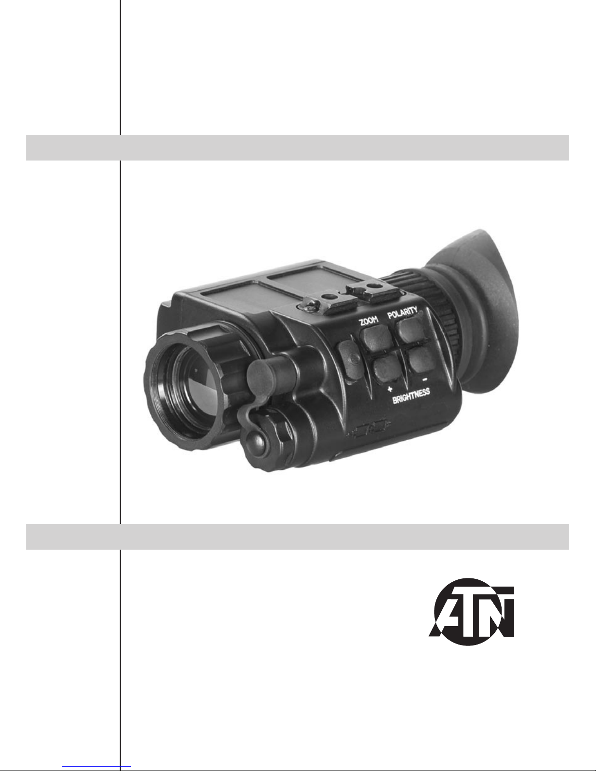
OTIS-14
Page 2
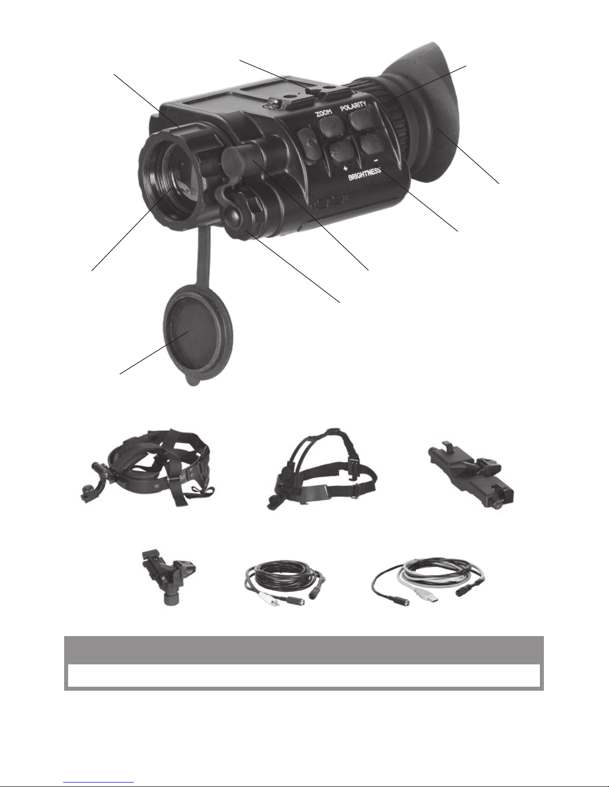
Eyepiece Diopter
Adjustment Ring
Rubber Eyecup
Battery Compartment Cover
Mounting Rail
Switchboard
Th is pro ducT conTain s naTur al rubb er l aTex which may caus e alle rg ic r eacTi ons
CAUTION:
Universal Connector Unit
Focusing Ring
Lens
Objective Lens Cover
Video Cable PC Cable
Head Mount Helmet Mount Dual Bridge
Adapter
The information in this manual furnished for information use only, is subject to change without notice, is not to be
const rue d as a com mit ment by AT N C orp.
ATN Cor p. as sum es no responsib ility or liabil ity fo r any err ors or in acc ura cies t hat may appear in this b ook .
©2009 ATN Corp. All right reserved.
Page 3

2
f e a t u r e s
spec ificat i o n
Magnification ........................................................1,8X
Objective Focal Length ........................................25 m m
FOV ......................................................................11° x 8°
Focus Range ........................................................from 1m to infin ity
Focus Adjustment ................................................Manual
Exit Pupil ..............................................................14mm
Eye Relief .............................................................25mm
Det e c tor Ty pe .......................................................Uncooled Microbolometer
Spectral Response...............................................7-14 μm
Pixels ....................................................................160 x 120
Pixel Size ..............................................................30 x 30 μm
Angular Resolution, mrad ....................................1,2
Thermal Sensitivity ..............................................< 0,1°C
Range to Detect a Human ....................................475 m
Output Format ......................................................Analog PAL / NTSC
Display .................................................................OLED matrix
Display Format .....................................................SVGA , 852 x 600 pxl
Color .....................................................................Monochrome
Digital ZOOM .......................................................Fixe d 2x (op tio nal 5x)
Brightness Adjustment .........................................Manual
Contrast Adjustment ............................................Automatic
Available User Interfaces .....................................From out sid e PC throu gh USB interface
Power Supply .......................................................2 x 3V, 123At ype
Start-Up Time .......................................................< 3 sec
Operating Ti me w / one bat ter y pack .....................4 hrs
Extern al Power Sup ply .........................................DC 6V, 50 0 mA
Operating Temperature Range ............................from -20 °C to + 5 0°C
Waterproof ...........................................................Yes, u p to 10m submersion
Dimensions ..........................................................118 x 78 x 54 mm
Weight (w/batteries) .............................................0,34 kg
a p p l i c a t i o n
The OT IS -14 i s a thermal s ys te m inte nd ed fo r law e nf or c e ment, mi li ta ry a nd c o mmercial u se s. It is bu il t
aro und st ate o f the art un c ooled ther mal im aging techn o logy, h i ghly inte grate d DSP-bas e d ele ctroni c s
and a comp act , light we igh t system.
The OTIS-14 thermal monocular provides the excellent image quality that is unaffected by lights or
shadows that seriously hamper the image quality of image intensified night vision. Total darkness,
camouflage or bright lights will not affect the sensitivity of these units.
The included and optional accessories provide for the versatility of the monocular. You can put it on a
headset or o n a helmet, co nne cted to anoth er mono cul ar to b uild a bin ocular syste m etc.
The ATN OTIS-14’s superior performance, compact size, comfort of wear and cost efficiency makes it
the perfect thermal imaging device.
* ATN reserves the right to change the above specifications at any time without notice
• H igh resolution digital thermal im aging
• C ompact, li ght we ight and durable hou sin g
• H ead /helmet mountable for hands fre e us age
• H igh Qua lit y optics
• V ide o and computer ou tpu t
• V ide o / Image p ola rit y se lection
• Waterproof
Page 4

3
o p e r a t i o n
Insert the two Lithium batteries (123A type) into the unit according to the polarity indications on the battery compartment. Press
the ON /OFF button to turn the monocular on. Remove the lens
cap.
Ad jus t th e proper eye pie ce d iopter and ob jec tive lens foc using.
The rotation of the Focusing Ring changes the position of the
objective lens in respect of the receiver focal plane array. In this
way the op era tor can adj ust the unit in orde r to see the target s at
various ranges with the same good contrast.
Cover protects the objective assembly from mechanical damage.
The operator can adjust the eyepiece diopter of the monocular for his/her own eyesight by rotating
Eyepiece Diopter Adjustment Ring.
Eyecup provides for the comfortable eye position and for the prevention of flash reflections onto the
operator ’s face w hich is cri tic al i n the f iel d and tactical activities.
Select the desired operation mode by pressing the switchboard
buttons.
With the «ZOOM» button you can activate a gradual adjustment
of the digital zoom preset in the mo nocular ad jus tme nts.
The «POLARITY» button switches the direct display mode into
the reverse one, i.e. from hot-white/cold-black into hot-black /
cold-white mode.
Each s hort pus h of the bu ttons «BRI GHT NESS + » or «BRIGHTNESS –» raises or lowers the display brightness, correspondingly, in stepwise way.
To turn the monocular off press the ON/OFF button.
s e t t i n g
The working settings of this thermal monocular may be customized by means of a PC.
Instal l th e so ftwa re i nto the PC from the CD/DVD s upplied in the
package of each OTIS-14 unit. Connect the monocular to the PC
through the included USB cable. The USB Cable is an interface
link between the thermal monocular and the external PC, and it
accepts the external power supply at the s ame time.
IMPORTANT: When the unit is to be powered with external
sourc es, fir st m ake su re t he b atteries have bee n taken ou t .
The ther mal mono c ular OT IS-14 ca n be powered eith er f rom the
included batteries or from any external source. Switch the monocular o n, star t th e auxi lia ry software an d introduc e all t he need ed or desirable s ettings in to it.
v i d e o o u t p u t
The monocular incorporates a sealed Connector used for video
transmission and to connect external power sources. The package of the thermal monocular OTIS-14 includes external connectio n V ideo Ca bl e. Vid eo Cable a t ta c hes th e m onocular to the
video facilities for video recording or video transmission to the
external display, though at the same time it accepts the external
power supply.
IMPORTANT: When the unit is to be powered with external
sourc es, fir st m ake su re t he b atteries have bee n taken ou t .
External Power
Supply Connector
External Power
Supply Connector
USB Connector
Video Connector
Page 5

4
h e a d m o u n t (o p t i o n a l )
The operator can mount the monocular onto the head bracket
using any of two Mounting Rail located on the opposite sides
of the body, to be able to see through the eyepiece with his /her
right or left eye correspondingly.
To mount t he OTIS-14 to a headmount, p erform the followin g :
1. Loosen th e screw ( A) . Push th e button ( B) a nd insert th e r a il of
the OTIS -14 in to the soc ket (C) of the headset.
2. Place the headmo unt wi th OTIS-14 o nto a head.
3. Loosen the screw (A) and move the unit along the rail for eye
relief adjustment.
4. The OTIS-14 headmount has a flip-up mechanism. Push the
button (D) on the side of mount and lift the unit up until the unit
fixates in the top pos iti on.
5. Push t he s ame but ton (D) to lower OTIS-14 to the vie win g position.
6. The OTIS-14 can be placed onto the right or left eye. In order to readjust the monocular for use with
the ot he r eye, t ak e the un it of f t he adapter, tur n t he u nit to o th er side (for 180º ) and mount it o n the he ad mount adapter through the rail on this side. Push the button (E) and move the device along the slide-rail
(F) for co mfortable position.
h e l m e n t m o u n t (o p t i o n a l )
Attachment of OTIS-14 to a standard PASGT helmet. The Helmet mount fits securely onto helmet
via a rugged strapping device and grooved hooks. With helmet
mount, the OTIS-14 can be positioned directly in front of user’s
eyes or flipped up out of viewing position.
1. Inst all the mount onto h elm et as s how n on th e pi ctu re.
2. Tig hten and fixate the st rap s (A)
3. Att ach the monocu lar to the rail.
4. Loosen screw (C). Push button (B) and insert the bracket of
the OTIS -14 in to rai l (D) of the helmet mount.
5. Place the helmet wi th OTIS-14 o nto he ad.
6. Loosen the screw (C) and move the unit for proper eye relief
adjustment.
7. The OTIS-14 he lm et mount h as a f lip - up mechanis m. Pu sh the
but ton (E) on the sid e of mo unt and li ft t he unit up unt il the uni t fixates in the top po sit ion.
8. Push the s ame but ton (E) to lower OT IS-14 to vie win g position.
9. The OTIS-14 can be placed onto the right or left eye. In order to readjust the monocular for use with
the othe r ey e, t ake the u nit o f f the head moun t ada pter, turn the u nit to ot her s ide ( for 180º ) and m ount it
on the adapter through the rail on this side. Push the button (E) and move the device along the slide-rail
(F) for co mfortable position.
e x t e r n a l p o w e r s o u r c e
IM PORTANT: When the unit is to be powered with exter nal sources, first make sure the b atter ies have
been taken out.
To connect an external power source you can use any of the cables of the monocular package. As an
external power source, a standard network controller with outer voltage of 6V and current of over 0.5A
can be app lie d.
Remove the protective cover off the connector input and attach the cable. To connect an external
sourc e, we recommend you to us e a 6mm standard double - pol e socket in t he way th e positive contact
is the central contact.
B
C
A
D
E
F
B
C
A
D
E
F
A
Page 6

5
w a r n i n g s a n d c a u t i o n s
IMPORTANT!
DO NOT DISASSEMBLE THE MONOCULAR.
KEE P YOUR OT IS-14 SAFE F ROM OPERATIO NAL AND TRANSPO RTATIO N IM PACTS .
WAITING FOR ONE HOUR BEFORE YOU SWITCH THE MONOCULAR ON IS HIGHLY RECOM-
MEN DABLE AFTER YOU BRIN G IT INTO THE WAR M RO OM F ROM THE COLDER OUT SIDE .
WHEN YOU DO NOT INTEND TO OPERATE YOUR MONOCULAR FOR 10 FOLLOWING DAYS WE
ADVISE YOU TO TAKE THE BAT TERY O UT O F TH E BAT TERY COMPART MEN T.
PROVIDE FOR TIMELY SERVICE MAINTENANCE OF THE UNIT.
If you use the rubber eyecaps for a long period of time, you may suffer skin inflammation. If you develop
any symptom s, consult a d octor imme diately.
t r o u b l e s h o o t i n g
Q: The im age is absent on the screen of goggles.
S: The batteries are discharged. Replace the batteries.
Q: The br ightne ss of the i mag e on th e sc ree n is low.
S: Th e batteries has a low voltage. Replace the bat ter ies.
Page 7

6
1 y e a r p r o d u c t w a r r a n t y
This product is guaranteed to be free from manufacturing defects in material and workmanship under
normal use for a period of 1 (one) years from the date of purchase. In the event a defect that is covered
by the foregoing warranty occurs during the applicable period stated above, ATN, at its option, will eithe r re pair or r epla ce th e pr oduct , an d suc h act ion o n th e par t of ATN sh all be th e fu ll ex tent of ATN’s li ability, and the Customer’s sole and exclusive remedy. This warranty does not cover a product (a) used
in other than its normal and customary manner; (b) subjected to misuse; (c) subjected to alterations,
modifications or repairs by the Customer of by any party other than ATN without prior written consent of
ATN; (d) special order or “close-out” merchandise or merchandise sold “as-is” by either ATN or the ATN
dealer; or (e) merchandise that has been discontinued by the manufacturer and either parts or replacement u nits a re not avai la ble du e to re as ons beyond t he contr ol of ATN. AT N shal l not b e respons ib le fo r
any defects or damage that in ATN’s opinion is a result from the mishandling, abuse, misuse, improper
storage or improper operation, including use in conjunction with equipment which is electrically or
mechanically incompatible with or of inferior quality to the product, as well as failure to maintain the environmental conditions specified by the manufacturer. CUSTOMER IS H ERE BY N OTIFIED THAT OP-
ERAT IO N O F T HE EQ UI PM ENT D UR ING D AYL IGHT H OU RS O R U ND ER A NY EXC ES SI VE LI GHT
CONDITIONS MAY PERMANENTLY DAMAGE THE INTERNAL COMPONENTS OF THE UNIT AND
SAID DA MAGE WILL NOT BE C OVERED U ND ER T HIS WARRANTY. This warranty is extended only
to t he or iginal purch a ser. An y bre ach of this warr a nty sh all b e waived un less t he cus tomer notif ies ATN
at the address noted below within the applicable warranty period.
The customer understands and agrees that except for the foregoing warranty, no other warranties
written or oral, statutory, expressed or implied, including any implied warranty of merchantability or
fitness for a particular purpose, shall apply to the product. All such implied warranties are hereby and
expressly disclaimed.
Limitation of liability
ATN will not be liable for any claims, actions, suits, proceedings, costs, expenses, damages or liabili-
ties a rising o ut of t he use of thi s produc t. O perat io n and u s e of t he prod uc t are t he sole r e sponsib ility of
the Customer. ATN’s sole undertaking is limited to providing the products and services outlined herein
in accordance with the terms and conditions of this Agreement. The provision of products sold and
services performed by ATN to the Customer shall not be interpreted, construed, or regarded, either
exp ressly o r impl i ed, a s being for t he benef it of or cre ating a ny o bl igati on tow ard an y thir d party o f legal
entity outside ATN and the Customer; ATN’s obligations under this Agreement extend solely to the
Customer. ATN’s liability hereunder for damages, r egardless of the form or ac tion, shall not ex-
ceed the f ees o r o t h e r charges p ai d t o AT N by the cu st om er or customer’s d e aler. ATN s ha ll not ,
in any event, be l ia bl e f or special, in di re ct, in ci de ntal , o r c on s e quential dam ag es, i nc lu di ng , b ut
not li mi te d to, lost in co me , l o st reve nu e, or lost prof it , w he th er s uc h d am ag es were foreseeabl e
or not at the time of purchase, and whether or not such damages arise out of a breach of warranty, a bre ach of agre ement, neglige nce , st ric t liability or any o ther th eory of lia bil ity.
Product warranty registration
In order to validate the warranty on your product, ATN must receive a completed Product Warranty
Registration Card for each unit or complete warranty registration on our website at www.atncorp.com.
Please complete the included form and immediately mail it to our Service Center: ATN Corporation,
1341 San Mateo Avenu e, Sou th San Francisco, CA 9 4080.
Obtaining warranty service
To o btain war rant y ser vi ce on you r un it, p leas e cont act o ur C usto mer S ervic e depa r tmen t and requ est
an RM A n umber. Once yo u have re c eived y our RMA # p lease m ar k this # o n t he outs id e o f the s hi pp in g
box and take or send the product, postage paid, with a copy of your sales receipt to our service center,
ATN Corporation at the address noted above. All merchandise must be fully insured with the correct
post ag e ; ATN w ill not be re sp onsibl e for i mprope r post ag e or m i ssing or dam aged me rc handi se duri ng
shipment. Packages that do not have an RMA # clearly marked on the outside of the package will be
delayed in being processedt.
11092008
Page 8

For customer service and technical support, please contact
American Technologies Network Corp.
North American Office
1341 San Mateo Avenue, Sout h San Fran cisc o, CA 94080
Toll Free Phone: 800-910-2862
Phone: 650-989-5100; fax: 650-875-0129
www.atncorp.com
©2009 ATN Corporation
 Loading...