

Page 1
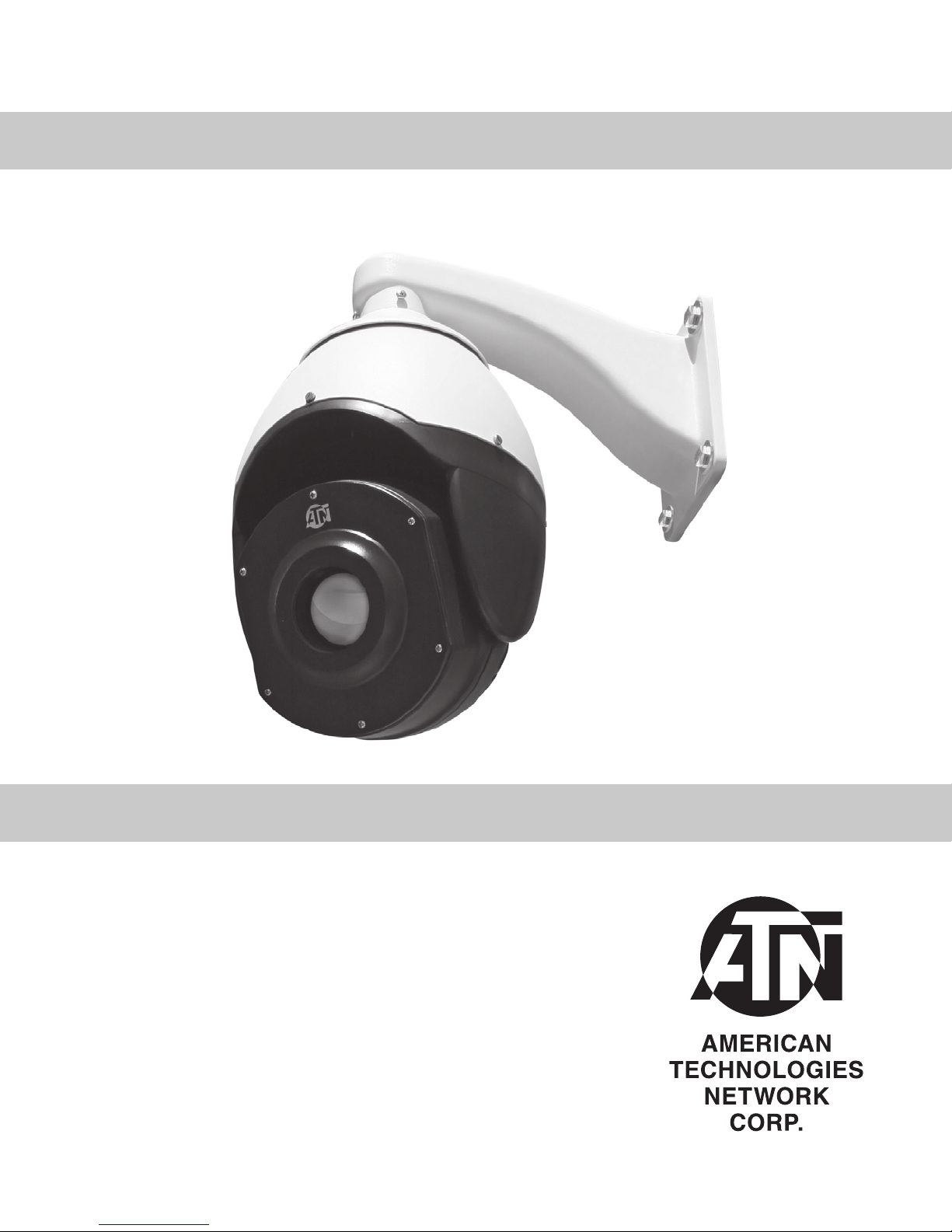
TASC Series
STAND-ALONE THERMAL
PAN & TILT SECURITY CAMERAS
operator’s manual
Important Export Restrictions! Commodities, products,
technologies and services contained in this manual are
subject to one or more of the export control laws and
regulations of the U.S. Government and they fall under the
control jurisdiction of either the US Department of State or the
US BIS-Department of Commerce. It is unlawful and strictly
prohibited to export, or attempt to export or otherwise transfer
or sell any hardware or technical data or furnish any service to
any foreign person, whether abroad or in the United States, for
which a license or written approval of the U.S. Government is
required, without first obtaining the required license or written
approval from the Department of the U.S. Government having
jurisdiction. Diversion contrary to U.S. law is prohibited.
OPERATOR’S MANUAL (TASC Series) REV. 1 – SEPT., 2014
Page 2

Register your product warranty online at
www.atncorp.com/warranty
Manual (TASC Series) Revision 1 – September, 2014
The information in this manual furnished for information use only, is subject to
change without notice, is not to be construed as a commitment by ATN Corp.
ATN Corp. assumes no responsibility or liability for any errors or inaccuracies
that may appear in this book.
© 2014 ATN Corp. All right reserved.
Page 3

SAFETY SUMMARY
STUDY CAREFULLY THIS MANUAL BEFORE TURNING ON
AND OPERATING THIS PRODUCT.
CAUTIONS
The TASC Series Stand-Alone Thermal Pan & Tilt Security Cameras are precision electro-optical instruments and requires careful
handling. To provide safe use of the systems the following instructions should be observed:
• Do not dismantle the device.
• Keep the device clean; protect it from moisture, sharp temperature drops and shocks.
• Be careful not to touch the glass surfaces. If you put finger-prints on, or contaminate the glass surfaces, use only
clean and soft materials to clean it.
• Do not leave the device in on position during stops in operation.
• Remove the batteries from the device for the period of storage.
CAUTION:
THIS PRODUCT CONTAINS NATURAL RUBBER LATEX
WHICH MAY CAUSE ALLERGIC REACTIONS.
a
Page 4

WARNING
Be careful in transportation.
Damages caused by stress, strong vibration and soak should
be avoided during the transportation and storage process. Any
damage occurs in the retransportation after assembling is not in the
warrant prepared range.
WARNING
What should you do when the equipment fails.
If this equipment smoke, strange smell or function failure you
should turn off the power supply immediately and stop using it, then
contact with the company or dealer.
WARNING
Do not take the equipment apart or change its configuration.
Do not open the house arbitrarily; otherwise the damages would be
meeting. If the inner setting and repair are needed, please contact
the company or dealer.
WARNING
Do not put other stuff in the equipment.
Make sure that there are not flammable and metal stuff which will
cause fire short circuit, damage in equipment. If water or other liquid
flow in the equipment, turn the power supply off and cut the power
line, then contact with the company or dealer.
WARNING
Be far away from electric field and magnetic field.
The image will be influenced by electromagnetic field when the
equipment was fixed near the TV, transmitter, electromagnetic
equipment, electric motor.
WARNING
Avoid humidity, dust, high temperature.
To avoid damage, please don’ t fix the equipment in places with
smoke, high temperature, and humidity.
b
Page 5

WARNING
Clean.
Clean the equipment with soft cloth. Firstly, put the cloth into the
detergent solution, and then wring out water before you wipe the
equipment. Lastly. wipe again with dry clean cloth. Don’ t use gasoline, paint thinner and other chemicals to clean the shell of the
equipment, otherwise, it would distortion and paint peeling
WARNING
Do not image extremely high intensity radiation sources.
Do not image extremely high intensity radiation sources, such as
the sun, laser, arc welders, etc.This warning applies whether or not
the system is powered.
WARNING
Do not try to repair the unit by yourself.
Do not try to repair the unit by yourself. We shall not be responsible
for any problem caused by unauthorized amendment or repairing.
c
Page 6

TABLE OF CONTENTS
CHAPTER 1. INTRODUCTION . . . . . . . . . . . . . . . . . 1-1
1.1. General Information . . . . . . . . . . . . . . . . . . . . 1-2
1.1.1. Camera . . . . . . . . . . . . . . . . . . . . . . . . . . 1-2
1.1.2. Reports . . . . . . . . . . . . . . . . . . . . . . . . . . 1-2
1.1.3. Storage . . . . . . . . . . . . . . . . . . . . . . . . . . 1-2
1.1.4. Warranty Information . . . . . . . . . . . . . . . . . . . 1-3
1.2. Description and Data . . . . . . . . . . . . . . . . . . . 1-5
1.2.1. Description . . . . . . . . . . . . . . . . . . . . . . . . 1-5
1.2.2. Technical parameters . . . . . . . . . . . . . . . . . . . 1-7
CHAPTER 2. ASSEMBLY AND PREPARATION . . . . . . . . 2-1
2.1. Preparation . . . . . . . . . . . . . . . . . . . . . . . . . 2-2
2.1.1. Preparation for Use . . . . . . . . . . . . . . . . . . . . 2-2
2.1.2. Dimension drawing . . . . . . . . . . . . . . . . . . . . 2-2
2.2. Installation guide . . . . . . . . . . . . . . . . . . . . . 2-4
2.2.1. Wall mount . . . . . . . . . . . . . . . . . . . . . . . . 2-4
CHAPTER 3. OPERATION GUIDE . . . . . . . . . . . . . . . 3-1
3.1. General Information . . . . . . . . . . . . . . . . . . . . 3-2
3.1.1. Self test . . . . . . . . . . . . . . . . . . . . . . . . . . 3-2
3.1.2. Control the direction of camera . . . . . . . . . . . . . . 3-2
3.1.3. Scan . . . . . . . . . . . . . . . . . . . . . . . . . . . . 3-2
3.1.4. Set preset . . . . . . . . . . . . . . . . . . . . . . . . . 3-2
3.1.5. Call preset . . . . . . . . . . . . . . . . . . . . . . . . . 3-2
3.1.6. Program Tour . . . . . . . . . . . . . . . . . . . . . . . 3-3
3.1.7. Call Tour . . . . . . . . . . . . . . . . . . . . . . . . . . 3-3
3.1.8. Set Home Point . . . . . . . . . . . . . . . . . . . . . . 3-4
3.1.9. Left And Right Limit Scan . . . . . . . . . . . . . . . . . 3-4
3.1.10. Restore Factory Default . . . . . . . . . . . . . . . . . 3-4
3.1.11. Speed Dome Command List . . . . . . . . . . . . . . . 3-4
3.1.12. The monitoring program . . . . . . . . . . . . . . . . . 3-6
i
Page 7

CHAPTER 4. MAINTENANCE INSTRUCTIONS . . . . . . . . 4-1
4.1. Troubleshooting procedures . . . . . . . . . . . . . . . 4-2
4.1.1. Troubleshooting procedures . . . . . . . . . . . . . . . . 4-2
4.2. The general knowledge of RS485 . . . . . . . . . . . . . 4-3
4.2.1. Basic characteristic of RS485 . . . . . . . . . . . . . . . 4-3
4.2.2. RS485 transmitting distance . . . . . . . . . . . . . . . 4-3
4.2.3. Connect mode and terminal impedance . . . . . . . . . 4-3
4.2.4. Question in applications . . . . . . . . . . . . . . . . . . 4-4
CHAPTER 5. APPENDIX . . . . . . . . . . . . . . . . . . . . 5-1
ii
Page 8

HOW TO USE THIS MANUAL
• Usage
You must familiarize yourself with the entire manual before operating the equipment. Read and follow all warning notices.
• Manual Overview
The table of contents includes the paragraph number, paragraph
title, and page number. An index provides additional references to
the subject contents.
iii
Page 9

CHAPTER 1
INTRODUCTION
1-1
Page 10

1.1. GENERAL INFORMATION
1.1.1. CAMERA
This manual contains instructions for use in operating and maintaining the TASC Series Stand-Alone Thermal Pan & Tilt Security
Cameras. Throughout this manual, the TASC Series will be referred
to as the scope or TASC.
1.1.2. REPORTS
Reports from the user on recommendations for improvements are
encouraged. Send reports to the address below.
American Technologies Network Corp.
1341 San Mateo Avenue
South San Francisco, CA 94080
(800) 910-2862
(650) 989-5100
(650) 875-0129 fax
info@atncorp.com
www.atncorp.com
1.1.3. STORAGE
Storage of TASC should be done in the factory packing and after
a thorough PMCS as outlined in Section 4.1 of this manual. This
will ensure the camera remains in mission ready condition during
storage. Presence of acid and alkaline vapor, as well as of other
aggressive admixtures in the air is unacceptable.
1-2
Page 11

1.1.4. WARRANTY INFORMATION
3 YEAR PRODUCT WARRANTY
This product is guaranteed to be free from manufacturing defects in material
and workmanship under normal use for a period of 3 (three) years from the
date of purchase. In addition the uncooled thermal sensor array carries a 10
year warranty. In the event a defect that is covered by the foregoing warranty
occurs during the applicable period stated above, ATN, at its option, will either
repair or replace the product, and such action on the part of ATN shall be the full
extent of ATN’s liability, and the Customer’s sole and exclusive remedy. This
warranty does not cover a product (a) used in other than its normal and custom
ary manner; (b) subjected to misuse; (c) subjected to alterations, modifications
or repairs by the Customer of by any party other than ATN without prior written
consent of ATN; (d) special order or “close-out” merchandise or merchandise
sold “as-is” by either ATN or the ATN dealer; or (e) merchandise that has been
discontinued by the manufacturer and either parts or replacement units are not
available due to reasons beyond the control of ATN. ATN shall not be responsible
for any defects or damage that in ATN’s opinion is a result from the mishandling,
abuse, misuse, improper storage or improper operation, including use in con
junction with equipment which is electrically or mechanically incompatible with
or of inferior quality to the product, as well as failure to maintain the environmen
tal conditions specified by the manufacturer. This warranty is extended only to
the original purchaser. Any breach of this warranty shall be waived unless the
customer notifies ATN at the address noted below within the applicable warranty
period.
-
-
-
The customer understands and agrees that except for the foregoing warranty,
no other warranties written or oral, statutory, expressed or implied, including any
implied warranty of merchantability or fitness for a particular purpose, shall apply
to the product. All such implied warranties are hereby and expressly disclaimed.
LIMITATION OF LIABILITY
ATN will not be liable for any claims, actions, suits, proceedings, costs,
expenses, damages or liabilities arising out of the use of this product. Opera
tion and use of the product are the sole responsibility of the Customer. ATN’s
sole undertaking is limited to providing the products and services outlined herein
in accordance with the terms and conditions of this Agreement. The provision
of products sold and services performed by ATN to the Customer shall not be
interpreted, construed, or regarded, either expressly or implied, as being for the
benefit of or creating any obligation toward any third party of legal entity outside
ATN and the Customer; ATN’s obligations under this Agreement extend solely
to the Customer.
-
1-3
Page 12

ATN’s liability hereunder for damages, regardless of the form or action, shall
not exceed the fees or other charges paid to ATN by the customer or customer’s
dealer. ATN shall not, in any event, be liable for special, indirect, incidental, or
consequential damages, including, but not limited to, lost income, lost revenue,
or lost profit, whether such damages were foreseeable or not at the time of pur
chase, and whether or not such damages arise out of a breach of warranty, a
breach of agreement, negligence, strict liability or any other theory of liability.
PRODUCT WARRANTY REGISTRATION
In order to validate the warranty on your product, ATN must receive a completed
Product Warranty Registration Card for each unit or complete warranty regis
tration on our website at www.atncorp.com. Please complete the included form
and immediately mail it to our Service Center: ATN Corporation, 1341 San Mateo
Avenue, South San Francisco, CA 94080.
OBTAINING WARRANTY SERVICE
To obtain warranty service on your unit, End-user must notify ATN service
department by calling 800-910-2862 or 650-989-5100 or via e-mail service@
atncorp.com to receive a Return Merchandise Authorization number (RMA).
When returning please take or send the product, postage paid, with a copy of
your sales receipt to our service center, ATN Corporation at the address noted
above. All merchandise must be fully insured with the correct postage; ATN will
not be responsible for improper postage or, missing or damaged merchandise
during shipment.
When sending product back, please clearly mark the RMA# on the outside of the
shipping box. Please include a letter that indicates your RMA#, Name, Return
Address, reason for service return, Contact information such as valid telephone
numbers and/or e-mail address and proof of purchases that will help us to estab
lish the valid start date of the warranty. Product merchandise returns that do
not have an RMA listed may be refused or a significant delay in processing may
occur. Estimated Warranty service time is 10-20 business days. End-user/cus
tomer is responsible for postage to ATN for warranty service. ATN will cover
return postage/shipping to continental USA end-users/customers after warranty
repair only if product is covered by aforementioned warranty. ATN will return
product after warranty service by domestic ground service and/or domestic mail.
Any other requested, required or international shipping method the postage/
shipping fee will be the responsibility of the end-user/customer
.
1-4
Page 13

1.2. DESCRIPTION AND DATA
1.2.1. DESCRIPTION
a. Purpose
TASC Series Features Built-in Analytics Advanced Motion Detector
in TASC cameras utilizes a state of the art algorithm that significantly reduces false alarms normally caused by movement of natural (background) objects such as leaves, clouds or small animals.
Object Tracking function when activated will capture and track all
moving objects and register their path in the field of view. Object
Counting function counts all captured objects. Trip Wire function
allows users to set up any configuration of virtual tripwires in the
field of view, that when crossed in preset direction, will trigger an
alarm. Perfect solution for passages, driveways or perimeter security. Trip Wire can also be used to detect wrong direction movement
on roads. Speed measurement feature turns your TASC camera
into speed radar that automatically measures and records speed
of all moving objects in the field of view. When applied inside Clean
Zone can also set off an alarm when a moving object exceeds user
preset speed limit. Clean Zone solution allows users to set up a
perimeter and create alarm rules that best resolve specific security issues by activating any combination of functions mentioned
above as well as Clean Zone specific algorithms such as Loitering Detection and Dropped Objects Detection. Loitering Detection
function sets off an alarm if an object stays in the Clean Zone longer
than a specified period of time. Dropped Objects Detection function
alarms user of all objects left in the field of view. Tampering alarm
informs an operator if the camera is mechanically manipulated with
or if the view is obscured. ATN Corp is proud to present the new
TASC series Thermal Acquisition Security Cameras! 18 years of
experience in enhancing vision, vast expertise in development of
thermal devices and recent advances in electronics enabled us to
create these easy to use products with almost unmatchable set of
skills that also come at very reasonable price. Our new cameras
utilize advanced thermal technology and optics used in the universally recognized Thor series scopes, together with Pan/Tilt capa-
1-5
Page 14

bilities, state of the art built-in analytics and features like autofocus
that were previously available only in top-end professional models.
TASC series caters to the most important need we all share - the
need for security. We truly believe that it can become an invaluable
instrument in outperforming potential threats to personal security
and safety of your possessions.
b. Function Description
1. Focus length/rotation speed auto matching technology
In the situation that focal length is long, the imager will be distorted because thermal speed dome responses so fast that even
a tender touch of joystick could make the picture shift rapidly. Base
on human design, this speed dome thermal imaging camera can
automatically adjust pan and tilt speed according to the focal length
to make the manual trace operation easier.
2. Automatically flip
If operator keeps press the joystick after reaching the limitation in
vertical direction, the lens would automatically flip 180°, so we can
monitor the back scene.
3. Set and call preset
Preset is a function that we can store the angle of PTZ and the
length of focus to the memory, and the thermal speed dome could
adjust itself to reach the angle of PTZ and the length of focus when
you call the preset.
4. Tour
Automatic tour, which arranges presets in the wanted order and
dwell time by programming,is a build-in function of this thermal
speed dome. With a command, the camera of thermal speed dome
would tour automatically and continuously according to the route
and dwell time preprogrammed.
5. Automatically scan
This high speed dome camera can automatically and repeatedly
scan 360°in both high speed and slow speed.
1-6
Page 15

6. Limit scan
To set the starting point of limit scan by using the limit start command in the control keyboard,then control the joystick to move to
the end point of limit scan with a certain speed. After calling the limit
scan, camera will automatically scan between the start and end
points with the speed which joystick moving.
7. Home point
Home place is a function that if there is no operation in a long time,
dome thermal camera would back to a certain important preset
place. Waiting time before home point function starting is from 1 to
255 second.
c. Features
TASC has the following important features:
• Advanced Thermal Detectors with resolution 336x256 or
640x515 pixels.
• High quality thermal image with 9/30/60 Hz frame rate.
• Built-in video analytics.
• Designed with low power consumption, standard 8 inch all-al-
loy housing.
• 360° horizontal continuous rotation. horizontal for 60°/sec;
vertical for 45°/sec.
• Support 128 preset positions, 5 tour routes.
• Against thunder and water, meet IP66 requirements.
• Support automatic reset when the preset has a wrong position.
• Periect used tool for middle range surveillance, even in total
darkness, light fog or smoke.
1.2.2. TECHNICAL PARAMETERS
Technical parameters of ATN thermal pan&tilt smart camera see
table below
1-7
Page 16

TASC
640-50
TASC
640-26
TASC
640-13
TASC
336-50
TASC
336-26
From -40°F to +140°F (-40°C / +60°C)
TASC
336-13
TASC
336-7
Detector type FLIR
MODEL
Tilt speed 0.5° to 120°/s
Home point 1-255s (adjustable)
Array size 320x240 pixels 640 x 480 pixels
Frame rate 60 hz/ 9Hz 30 hz/ 9Hz
Detector
characte-
Lens 7 mm 13 mm 26 mm 50 mm 13 mm 26 mm 50 mm
Pixel size 17μm
ristics
Focus Fixed
Field of View 44.5° 25° 12.5° 6.5° 45.4° 23.6° 12.5°
Calibration Automatic
Optics
Pan range 360° rotating and back-and-forth
Auto flip After tilt 90°, image will automatically flip 180°
Tilt range 360° rotating and up-and-down
Built-in
Control mode IP / Pelco D
Polarity White & black hot
Video output IP protocol / composite
Operating
temperature
Storage temperature From -58°F to +149°F (-50°C / +65°C)
Weatherproof rate IP66
Input Voltage DC 12 V
Power dissipation 3W
Pan& Tilt
Image
Output
Environment
Power supply
Size 13.8” x 8.7” x 8.7” / 350 mm x 220 mm x 220 mm
Weight 9.1 lb/4.1 kg 9.2lb/4.2 kg 9.2lb/4.2 kg 9.5lb/4.3 kg 9.2lb/4.2 kg 9.2lb/4.2 kg 9.5lb/4.3 kg
Physical cha-
racteristics
1-8
Page 17

CHAPTER 2
ASSEMBLY AND PREPARATION
2-1
Page 18

2.1. PREPARING FOR INSTALLATION
2.1.1. PREPARATION FOR USE
1. Basic requirement
• All electrical work should comply with the latest local electrical
regulation, fire precautions legislation and other relative legislations and regulations.
• Check that whether accessories are complete or not according
to packing list. If not, please contact the seller.
• Make sure that the applied and installed place meets the
requirement of installation.
2. Check the structure of the applied and installed place
• Make sure that there is enough room to install this product and
its accessories.
• Make sure that the ceiling, wall and bracket which would install
this thermal speed dome should be able to endure as 4 times
weight as speed dome.
3. Set DIP switch
• Set DIP switch according to protocol, baud rate and speed
dome IP address .
• RS485 jumper setting.
4. Please keep all the safe packing material of thermal dome
Please keep the safe packing material of thermal dome after taking
apart the package. If there are some problems with the dome,
please pack with the original package and send it back to manufacturer.
NOTE
Non-original package will cause the unexpected damage
during transportation.
(Detailed information can be found in Appendix)
2.1.2. DIMENSION DRAWING
Appearance:
2-2
Page 19

2-3
Page 20

2.2. INSTALLATION GUIDE
2.2.1. WALL MOUNT
NOTE
If the machine is installed outside, make sure the air tightness
of thermal speed dome is good and keep away from the place
with high temperature or humidity.
There are so many kinds of brackets, so we just introduce the
process of installation of thermal speed dome. The installation of
bracket please refer to bracket installation guide.
Steps a. Take the bracket base as a template to mark the Posi-
tions Of the holes which should be drilled in the wall.
Steps b. Put video cable, power supply cable and control signal
through the cavity of bracket. Leave cables enough long outside
the bracket.
2-4
Page 21

CHAPTER 3
OPERATION GUIDE
3-1
Page 22

3.1. GENERAL INFORMATION
NOTE
These operating instructions cover the basic operation and
features of the dome.
3.1.1. SELF TEST
After the intelligent speed dome was powered on, the camera pan
and tilt automatically. And then it zoom from the nearest position
and stop in the farthest position. It could ensure that the speed
dome is in working order by self-testing.
3.1.2. CONTROL THE DIRECTION OF CAMERA
We should press the number of IP address of camera, and then
press SHOT key to call the camera to monitor, then we can make
thermal camera move up or down, left or right by moving joystick.
3.1.3. SCAN
Call preset 120 (Detailed information about how to call preset will
follow in this page) to start slow scan. Call preset 121 to start fast
scan.
3.1.4. SET PRESET
Press the ACK key and SHOT key in the keyboard at the same time
to enter setting status. Firstly, move the joystick to find a desired
preset position and focal length, then press the number key to enter
the preset number. Secondly, press SHOT key, then press ON key.
At last, press ACK key and SHOT key at the same time to exit setting status.
3.1.5. CALL PRESET
Enter the preset number then press SHOT key to call the preset
wanted, then the camera will immediately move to the preset position and automatically change to focal length of preset you called.
3-2
Page 23

3.1.6. PROGRAM TOUR
Tour is a function that camera could automatically move among
some presets according to a programmed route and dwell time after
calling it.
• Five tour(100,101,102,103,104) is available in this product.
• Each tour have 16 presets. If the presets are less than 16, the
last preset number should be set 119 ,then exit. If the presets
are more than 16, system will automatically save the former 16
presets. The dwell time must be set more than 3 seconds. If the
dwell time is less than 3 seconds, the system will automatically
set 3 seconds as default dwell time.
Case 1: Set the first tour which includes 5 presets. The number of
the five presets are 1 → 10 → 15 → 16 → 21, dwell time is 6 seconds.
• Set preset 100 which corresponding to the first tour (please
refer the section about how to set preset)
• Set preset 6 which corresponding to the dwell time.
• Set preset 1 (the tour consists of preset 1)
• Set preset 10 (the tour consists of preset 10)
• Set preset 15 (the tour consists of preset 15)
• Set preset 16 (the tour consists of preset 16)
• Set preset 21 (the tour consists of preset 21)
• Set preset 119 (exist the tour programming)
• Press ACK and SHOT at the same time to exit setting status.
3.1.7. CALL TOUR
Call tour 1 by calling preset 100, Call tour 2 by calling preset 101,
call tour 3 by calling 102, call tour 4 by calling preset 103,call tour 5
by calling preset 104.
Case 2: The Tour 1, which have five presets in the order like 1 → 10
→ 15 → 16 → 21, and the dwell time of ever preset is six seconds,
was programmed.
Call preset 100 which corresponding to tour 1 (please refer the section about how to call preset).
3-3
Page 24

After calling tour 1, the speed dome camera will move like this: 1
→ dwell six seconds → 10 → dwell six seconds → 15 → dwell six
seconds → 16 → dwell six seconds → 21 → dwell six seconds → 1
(repeat the tour)...
3.1.8. SET HOME POINT
Home point is a function that speed dome camera will automatically move to a certain important preset which is set beforehand,
after a period of time without any operation made by operator. The
waiting time before entering into home status can be set from 1 to
255 seconds.
• Firstly, set a preset which you want be the home point.
• Set preset 121 to enter home point setting status.
• Set preset 122 to start home point.
• Set preset 123 to delete home point.
3.1.9. LEFT AND RIGHT LIMIT SCAN
User could set the left scan limit and right scan limit to make thermal
speed dome scan between them.
Call the camera to monitor (Enter IP address of camera then press
SHOT key).
Set preset 110 to set lift limit, then move the joystick to the position
where you want to set the right limit. Then set preset 111 to set right
limit. At last, move back 30 degree to avoid the speed dome camera
does not pan in the right direction.
3.1.10. RESTORE FACTORY DEFAULT
Call preset 150 would eliminate all the function which was set by
customer.
3.1.11. SPEED DOME COMMAND LIST
NOTE
Symbol “+” is stand for that the function is available.
3-4
Page 25

Preset number Speed dome / camera control content
Call
preset
Set
preset
The functions would fail to be operated if the tour wasn’t programmed by customer
beforehand
99 Reset +
100 Start the first programmed tour +
101 Start the second programmed tour +
102 Start the third programmed tour +
103 Start the fourth programmed tour +
104 Start the fifth programmed tour +
115 Start the first default tour (1-16 presets) +
116 Start the second default tour (17-32 presets) +
117 Start the third default tour (33-48 presets) +
118 Start the fourth default tour (49-64 presets) +
119 Start the fifth default tour (65-80 presets) +
110 Light Limit point +
111 Right Limit point +
112 Call lift and right limit scan +
113 Open lens/rotation auto match function +
114 Close lens/rotation auto match function +
120 Pan slowly +
121 Pan quickly +
121 Set Home point +
122 Open Home point +
123 Delete Home point +
150 Restore factory default +
Open/Close Enter/ exist menu (some models are available)
3-5
Page 26

3.1.12. THE MONITORING PROGRAM
The monitoring program of TASC cameras: ADM (ATN Device Manager).
When launched the program starts searching in the local network
for the compatible cameras and adds them to the list “Device list».
If the camera is outside the local network it should be added manually. When you add the camera (both automatically and manually)
you can see the “window” with preview video below. When you
choose the camera from the list “Device list” the Camera Control
Menu appears in the list “Device”. In order to view the video from
the camera you should choose the position “Live video” from the
list “Device”.
3-6
Page 27

CHAPTER 4
MAINTENANCE INSTRUCTIONS
4-1
Page 28

4.1. TROUBLESHOOTING PROCEDURES
4.1.1. TROUBLESHOOTING PROCEDURES
Troubleshooting procedures are listed in table below.
PROBLEM
Thermal
speed dome
have no
action and
there is no
picture in
monitor after
power is on.
After self
testing,
keyboard
can’t control
Thermal
speed dome.
POSSIBLE
REASONS
1. The end of 24V
AC power supply
didn’t connect with
speed dome in right
way.
2. Power failure or
transformer breakdown.
1. IP address Switch
of speed dome set
incorrectly.
2. Reverse connection and open circuit
of RS485 control
bus.
SOLUTION
1. Check whether thermal speed
dome connect to 24V AC power
supply. Make sure that the well
connection between speed dome
and 24V AC power supply.
2. Check whether the power supply
is in working order and whether 24V
AC transformer work normally.
1. Reset DIP switches according to
DIP switch setting table.
And make sure that the IP address
speed dome is the same with that
of keyboard.
2. Check connection of RS485
control bus, guarantee well and
correct connection.
3. RS485 control
bus breakdown.
Fan
don’t work.
The picture
is fuzzy.
1. Poor fan connection.
2. Ambient temperature is below 10°C
1. Thermal speed
dome is in the
manual focus status.
2. Transparent lower
dome is not clean.
4-2
3. Refer to common sense of
RS485 control bus.
1. Make sure the well connection. If
fan don’t work when connection is
well, please contact supplier.
2. Make sure that thermal speed
dome work in proper temperature.
1. Change the manual focus status
to auto focus status.
2. Clean transparent lower dome.
Page 29

4.2.
THE GENERAL KNOWLEDGE OF RS485
4.2.1. BASIC CHARACTERISTIC OF RS485
RS485 is a half duplex communication bus whose impedance is
120Ω. Its carrying capacity is different because the different connection interface, IC is 32-128 actual load (including master equipment and slaves equipments).
4.2.2. RS485 TRANSMITTING DISTANCE
When 0.56 mm (24AWG) twisted pair line is used as the communication electric cable, there are different transmission distance
according to different Baud rate setting. Maximum transmission
distance and corresponding.
Baud rate
2400 BPS 1800 m 4800 BPS 1200 m
9600 BPS 800 m 19200 BPS 600 m
Maximum
distance
Baud rate
Maximum
distance
The max transmission distance would be shortened in conditions
as: when this product uses a slim communication electric cable
or the thermal speed dome is used in the environment with strong
electromagnetic interference or there are many equipments connected to control bus, vice versa.
4.2.3. CONNECT MODE AND TERMINAL IMPEDANCE
The RS485 requires daisy-chain connection mode, and two 120Ω
terminal impedances should be connected. The mode was showed
as figure 4.1. Simplified connection mode shows in figure 4.2, make
sure that the distance of D can’t be more than 23 feet (7 meters).
FIGURE 4.1
4-3
Page 30

FIGURE 4.2
4.2.4. QUESTION IN APPLICATIONS
In the actual construction, user often adopts y-junction connection
mode whose terminal impedance are connected with the furthest
two equipments (as B and D in figure 4.3). But it doesn’t comply
with the use requirement of RS485 industrial standard, so it would
lower the reliability of control signal by causing the problems such
as signal reflection and a weaker antiinterference ability in the
situation that there is long distance among every equipment. Its
reflecting phenomenon is that speed dome isn’t under the control
completely or under control off and on or can’t stop from automatically running. We advise to use RS485 allotter which can avoid
problems and increase the communication reliability in the situation mentioned above by change y-junction mode to the connection
mode complying with RS485 industrial standard.
4-4
FIGURE 4.3
Page 31

CHAPTER 5
APPENDIX
4-5
Page 32

SW2 SETTING — IP ADDRESS SETTING
In the following table,“1” stand for “ON” position in IP address
switch. “0”stand for “OFF” position in IP address switch.
Address
code
IP Address switch
1 2 3 4 5 6 7 8
1 1 0 0 0 0 0 0 0
2 0 1 0 0 0 0 0 0
3 1 1 0 0 0 0 0 0
4 0 0 1 0 0 0 0 0
5 1 0 1 0 0 0 0 0
6 0 1 1 0 0 0 0 0
7 1 1 1 0 0 0 0 0
8 0 0 0 1 0 0 0 0
9 1 0 0 1 0 0 0 0
10 0 1 0 1 0 0 0 0
11 1 1 0 1 0 0 0 0
12 0 0 1 1 0 0 0 0
13 1 0 1 1 0 0 0 0
14 0 1 1 1 0 0 0 0
Address
code
IP Address switch
1 2 3 4 5 6 7 8
30 0 1 1 1 1 0 0 0
31 1 1 1 1 1 0 0 0
32 0 0 0 0 0 1 0 0
33 1 0 0 0 0 1 0 0
34 0 1 0 0 0 1 0 0
35 1 1 0 0 0 1 0 0
36 0 0 1 0 0 1 0 0
37 1 0 1 0 0 1 0 0
38 0 1 1 0 0 1 0 0
39 1 1 1 0 0 1 0 0
40 0 0 0 1 0 1 0 0
41 1 0 0 1 0 1 0 0
42 0 1 0 1 0 1 0 0
43 1 1 0 1 0 1 0 0
15 1 1 1 1 0 0 0 0
16 0 0 0 0 1 0 0 0
17 1 0 0 0 1 0 0 0
18 0 1 0 0 1 0 0 0
19 1 1 0 0 1 0 0 0
20 0 0 1 0 1 0 0 0
21 1 0 1 0 1 0 0 0
22 0 1 1 0 1 0 0 0
23 1 1 1 0 1 0 0 0
24 0 0 0 1 1 0 0 0
25 1 0 0 1 1 0 0 0
26 0 1 0 1 1 0 0 0
27 1 1 0 1 1 0 0 0
28 0 0 1 1 1 0 0 0
29 1 0 1 1 1 0 0 0
44 0 0 1 1 0 1 0 0
45 1 0 1 1 0 1 0 0
46 0 1 1 1 0 1 0 0
47 1 1 1 1 0 1 0 0
48 0 0 0 0 1 1 0 0
49 1 0 0 0 1 1 0 0
50 0 1 0 0 1 1 0 0
51 1 1 0 0 1 1 0 0
52 0 0 1 0 1 1 0 0
53 1 0 1 0 1 1 0 0
54 0 1 1 0 1 1 0 0
55 1 1 1 0 1 1 0 0
56 0 0 0 1 1 1 0 0
57 1 0 0 1 1 1 0 0
58 0 1 0 1 1 1 0 0
4-6
Page 33

Address
IP Address switch
Address
IP Address switch
code
1 2 3 4 5 6 7 8
59 1 1 0 1 1 1 0 0
60 0 0 1 1 1 1 0 0
61 1 0 1 1 1 1 0 0
62 0 1 1 1 1 1 0 0
63 1 1 1 1 1 1 0 0
64 0 0 0 0 0 0 1 0
65 1 0 0 0 0 0 1 0
66 0 1 0 0 0 0 1 0
67 1 1 0 0 0 0 1 0
68 0 0 1 0 0 0 1 0
69 1 0 1 0 0 0 1 0
70 0 1 1 0 0 0 1 0
71 1 1 1 0 0 0 1 0
72 0 0 0 1 0 0 1 0
73 1 0 0 1 0 0 1 0
code
1 2 3 4 5 6 7 8
92 0 0 1 1 1 0 1 0
93 1 0 1 1 1 0 1 0
94 0 1 1 1 1 0 1 0
95 1 1 1 1 1 0 1 0
96 0 0 0 0 0 1 1 0
97 1 0 0 0 0 1 1 0
98 0 1 0 0 0 1 1 0
99 1 1 0 0 0 1 1 0
100 0 0 1 0 0 1 1 0
101 1 0 1 0 0 1 1 0
102 0 1 1 0 0 1 1 0
103 1 1 1 0 0 1 1 0
104 0 0 0 1 0 1 1 0
105 1 0 0 1 0 1 1 0
106 0 1 0 1 0 1 1 0
74 0 1 0 1 0 0 1 0
75 1 1 0 1 0 0 1 0
76 0 0 1 1 0 0 1 0
77 1 0 1 1 0 0 1 0
78 0 1 1 1 0 0 1 0
79 1 1 1 1 0 0 1 0
80 0 0 0 0 1 0 1 0
81 1 0 0 0 1 0 1 0
82 0 1 0 0 1 0 1 0
83 1 1 0 0 1 0 1 0
84 0 0 1 0 1 0 1 0
85 1 0 1 0 1 0 1 0
86 0 1 1 0 1 0 1 0
87 1 1 1 0 1 0 1 0
88 0 0 0 1 1 0 1 0
89 1 0 0 1 1 0 1 0
107 1 1 0 1 0 1 1 0
108 0 0 1 1 0 1 1 0
109 1 0 1 1 0 1 1 0
110 0 1 1 1 0 1 1 0
111 1 1 1 1 0 1 1 0
112 0 0 0 0 1 1 1 0
113 1 0 0 0 1 1 1 0
114 0 1 0 0 1 1 1 0
115 1 1 0 0 1 1 1 0
116 0 0 1 0 1 1 1 0
117 1 0 1 0 1 1 1 0
118 0 1 1 0 1 1 1 0
119 1 1 1 0 1 1 1 0
120 0 0 0 1 1 1 1 0
121 1 0 0 1 1 1 1 0
122 0 1 0 1 1 1 1 0
90 0 1 0 1 1 0 1 0
91 1 1 0 1 1 0 1 0
123 1 1 0 1 1 1 1 0
124 0 0 1 1 1 1 1 0
4-7
Page 34

Address
IP Address switch
Address
IP Address switch
code
1 2 3 4 5 6 7 8
125 1 0 1 1 1 1 1 0
126 0 1 1 1 1 1 1 0
127 1 1 1 1 1 1 1 0
128 0 0 0 0 0 0 0 1
129 1 0 0 0 0 0 0 1
130 0 1 0 0 0 0 0 1
131 1 1 0 0 0 0 0 1
132 0 0 1 0 0 0 0 1
133 1 0 1 0 0 0 0 1
134 0 1 1 0 0 0 0 1
135 1 1 1 0 0 0 0 1
136 0 0 0 1 0 0 0 1
137 1 0 0 1 0 0 0 1
138 0 1 0 1 0 0 0 1
139 1 1 0 1 0 0 0 1
code
1 2 3 4 5 6 7 8
158 0 1 1 1 1 0 0 1
159 1 1 1 1 1 0 0 1
160 0 0 0 0 0 1 0 1
161 1 0 0 0 0 1 0 1
162 0 1 0 0 0 1 0 1
163 1 1 0 0 0 1 0 1
164 0 0 1 0 0 1 0 1
165 1 0 1 0 0 1 0 1
166 0 1 1 0 0 1 0 1
167 1 1 1 0 0 1 0 1
168 0 0 0 1 0 1 0 1
169 1 0 0 1 0 1 0 1
170 0 1 0 1 0 1 0 1
171 1 1 0 1 0 1 0 1
172 0 0 1 1 0 1 0 1
140 0 0 1 1 0 0 0 1
141 1 0 1 1 0 0 0 1
142 0 1 1 1 0 0 0 1
143 1 1 1 1 0 0 0 1
144 0 0 0 0 1 0 0 1
145 1 0 0 0 1 0 0 1
146 0 1 0 0 1 0 0 1
147 1 1 0 0 1 0 0 1
148 0 0 1 0 1 0 0 1
149 1 0 1 0 1 0 0 1
150 0 1 1 0 1 0 0 1
151 1 1 1 0 1 0 0 1
152 0 0 0 1 1 0 0 1
153 1 0 0 1 1 0 0 1
154 0 1 0 1 1 0 0 1
155 1 1 0 1 1 0 0 1
173 1 0 1 1 0 1 0 1
174 0 1 1 1 0 1 0 1
175 1 1 1 1 0 1 0 1
176 0 0 0 0 1 1 0 1
177 1 0 0 0 1 1 0 1
178 0 1 0 0 1 1 0 1
179 1 1 0 0 1 1 0 1
180 0 0 1 0 1 1 0 1
181 1 0 1 0 1 1 0 1
182 0 1 1 0 1 1 0 1
183 1 1 1 0 1 1 0 1
184 0 0 0 1 1 1 0 1
185 1 0 0 1 1 1 0 1
186 0 1 0 1 1 1 0 1
187 1 1 0 1 1 1 0 1
188 0 0 1 1 1 1 0 1
156 0 0 1 1 1 0 0 1
157 1 0 1 1 1 0 0 1
4-8
189 1 0 1 1 1 1 0 1
190 0 1 1 1 1 1 0 1
Page 35

Address
IP Address switch
Address
IP Address switch
code
1 2 3 4 5 6 7 8
191 1 1 1 1 1 1 0 1
192 0 0 0 0 0 0 1 1
193 1 0 0 0 0 0 1 1
194 0 1 0 0 0 0 1 1
195 1 1 0 0 0 0 1 1
196 0 0 1 0 0 0 1 1
197 1 0 1 0 0 0 1 1
198 0 1 1 0 0 0 1 1
199 1 1 1 0 0 0 1 1
200 0 0 0 1 0 0 1 1
201 1 0 0 1 0 0 1 1
202 0 1 0 1 0 0 1 1
203 1 1 0 1 0 0 1 1
204 0 0 1 1 0 0 1 1
205 1 0 1 1 0 0 1 1
code
1 2 3 4 5 6 7 8
224 0 0 0 0 0 1 1 1
225 1 0 0 0 0 1 1 1
226 0 1 0 0 0 1 1 1
227 1 1 0 0 0 1 1 1
228 0 0 1 0 0 1 1 1
229 1 0 1 0 0 1 1 1
230 0 1 1 0 0 1 1 1
231 1 1 1 0 0 1 1 1
232 0 0 0 1 0 1 1 1
233 1 0 0 1 0 1 1 1
234 0 1 0 1 0 1 1 1
235 1 1 0 1 0 1 1 1
236 0 0 1 1 0 1 1 1
237 1 0 1 1 0 1 1 1
238 0 1 1 1 0 1 1 1
206 0 1 1 1 0 0 1 1
207 1 1 1 1 0 0 1 1
208 0 0 0 0 1 0 1 1
209 1 0 0 0 1 0 1 1
210 0 1 0 0 1 0 1 1
211 1 1 0 0 1 0 1 1
212 0 0 1 0 1 0 1 1
213 1 0 1 0 1 0 1 1
214 0 1 1 0 1 0 1 1
215 1 1 1 0 1 0 1 1
216 0 0 0 1 1 0 1 1
217 1 0 0 1 1 0 1 1
218 0 1 0 1 1 0 1 1
219 1 1 0 1 1 0 1 1
220 0 0 1 1 1 0 1 1
221 1 0 1 1 1 0 1 1
239 1 1 1 1 0 1 1 1
240 0 0 0 0 1 1 1 1
241 1 0 0 0 1 1 1 1
242 0 1 0 0 1 1 1 1
243 1 1 0 0 1 1 1 1
244 0 0 1 0 1 1 1 1
245 1 0 1 0 1 1 1 1
246 0 1 1 0 1 1 1 1
247 1 1 1 0 1 1 1 1
248 0 0 0 1 1 1 1 1
249 1 0 0 1 1 1 1 1
250 0 1 0 1 1 1 1 1
251 1 1 0 1 1 1 1 1
252 0 0 1 1 1 1 1 1
253 1 0 1 1 1 1 1 1
254 0 1 1 1 1 1 1 1
07052015
222 0 1 1 1 1 0 1 1
223 1 1 1 1 1 0 1 1
255 1 1 1 1 1 1 1 1
4-9
Page 36

For customer service and technical support, please contact
American Technologies Network Corp.
1341 San Mateo Avenue, South San Francisco, CA 94080
phone: 800-910-2862, 650-989-5100; fax: 650-875-0129
www.atncorp.com©
2014 ATN Corporation
 Loading...