

Page 1
ATN PS14
/
Night Spirit
MULTI-USE NIGHT VISION MONOCULAR
u s e r ` s g u i d e
Export of night vision equipment and optical sighting
equipment is controlled by the
U.S. Depar tment of State, Office
of Defense Trade Controls in
accordance with International
Traffic in Arms (ITAR), Title 22,
Code of Federal Regulations Part
120-130 and/or the Export Administration Regulations (EAR) U.S.
Department of Commerce. Illegal
export of these commodities is
strictly prohibited.
AMERICAN
TECHNOLOGIES
NETWORK
CORP.
Page 2
0.25m to Infinity
focus
24mm F 1:1.2 lens
for maximum clarit y
One 1.5 volt
battery
Single switch
button operation
+5/-6 Diopter
Built-in infra-red
illuminator
Rotating rubber
eyepiece
Protective cover/
daylight filter
Mounting
thread
The following image intensifier
tube confi gurations are available
for this unit:
Model Number
PS-14-4
PS-14-XR5
PS-14-3
PS-14-XD4
PS-14-CGT
PS-14-2
The information in this manual furnished for information use only, is subject to change without notice,
is not to be construed as a commitment by ATN Corp.
ATN Corp. assumes no respo nsibi lity or liability for any errors or inaccurac ies that may appear in this book.
©2005 ATN Corp. All right reserved.
Tube configuration
64-72lp /mm
Filmless Autogated (4th gen)
64-72lp /mm DEP
64lp /mm Generation 3
55- 64lp /mm DEP XD4
51-62lp /mm DEP
32-45lp/mm Generation 2
Page 3

FEATURES
• High Quality light intensifier tube
• Super fast lens system provides the user
with a clear and sharp image
• Built-in Infra Red illuminator lets you see
even in total darkness
• Interchangeble lenses for different mag-
nification
• Adjustable Flip-up headmount for hands
free use
• Automatic brightness control for high-light
protection
• IR-on and Low Battery indicators
• Rugged and versatile design
• Single switch knob operation
• Camera/camcorder-adaptable
• Helmet-mountable
• Weapon -mountable
• Flexible carrying case
• Uses one AA battery
• Waterproof 20 meters for 1 hour
• Two-year factory warranty
SPECIFICATIONS
Magnification .................................................... 1X (optional 3X, 5X)
Detection range ................................................ 250(Gen.2) or 300 (Gen.3) or 340(Gen.4)m/y
Recognition range ............................................ 175(Gen.2) or 225(Gen.3) or 300(Gen.4)m/y
Lens System ..................................................... 24 mm; F1:1.2
Field of view ...................................................... 40°
Range of Focus................................................. 0.25m to
Power Supply.................................................... 1.5 volt AA size battery
Battery Life ....................................................... 60 hours (20 hours with IR illuminator)
Operating Temp. ............................................... -51°C to +49°C (-60°F to +120°F)
Operating Temp. ............................................... -51°C to +85°C (-60°F to +185°F)
Waterproof. ....................................................... 20 m for 1 hour
Dimensions....................................................... 151x80x55 mm (6.7” x 2.5” x 4”)
Weight............................................................... 0.32kg (0.7 lb)
APPLICATION
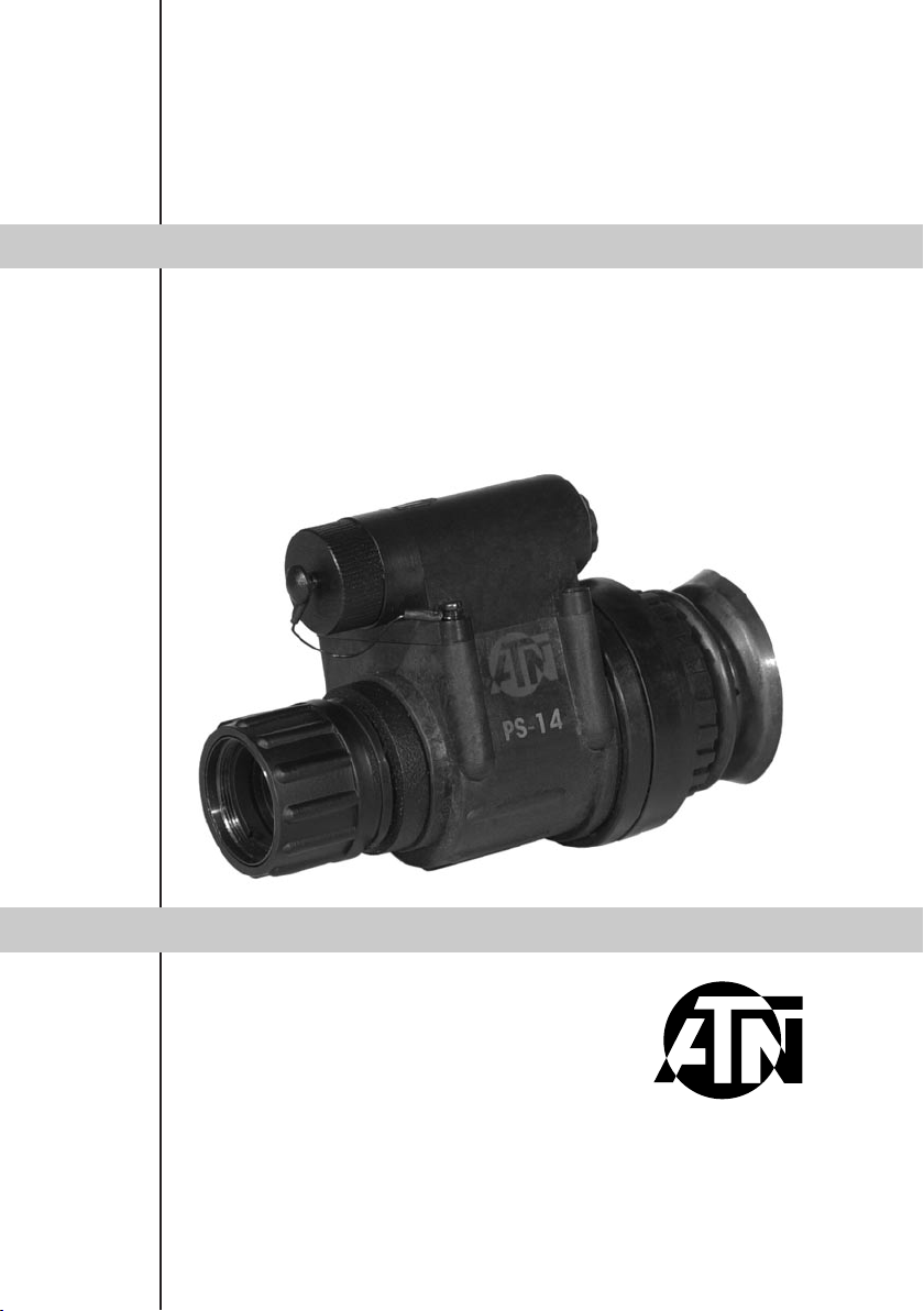
The PS-14 Multi-use Night Vision monocular is one of the most versatile night vision devices
available. This unit can be handheld, head-mounted for hands free usage, it is camera/ camcorder adaptable, and can be made into a 4x or 6.5x bi-ocular. This unit can also be weaponmounted. The intergrated IR illuminator enhances the ability of the user to read maps and oper
ate in confined, zero light areas. The PS14 is available with several image intensifier options to
meet a wide array of specification requirements.
The PS-14 night vision monocular is a complex opticoelectronic system for individual use. The
device consists of the objective lens assembly, eyepiece and the body. The body contains an
image intensifier tube assembly with an integrated high voltage power source and the battery
housing.
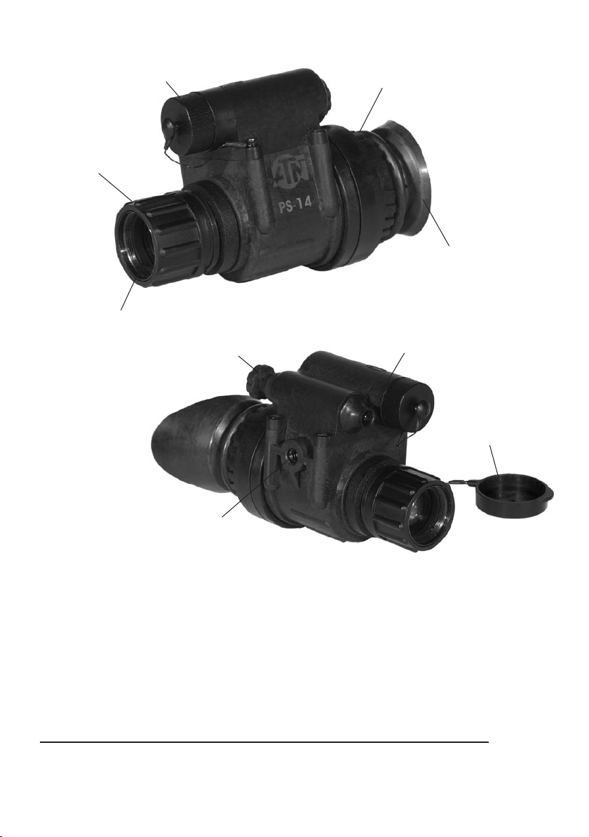
Objective lens protective cover is intended to protect the objective lens from dust and
scratches. It also will act as a daylight filter, allowing you to test the scope in daylight or other
bright light situations. The pinhole in the center of the protective cover allows the user to check
the operation ability of the device in daylight conditions.
NOTE: Do not test the scope in daylight conditions even with the daylight filter/lens cap on for
more than ten (10) minutes.
-
2
Page 4
4
OPERATION
• Take the monocular out of the case.
Operation
knob
• Next, remove the lens cap/daylight filter. Adjust the front lens for the distance of the focus.
You should not have to readjust the diopter.
• To turn the unit off, rotate the operation knob from “ON” position to “OFF” position.
• Install the battery into the housing with the polarity order
as shown on the scope. Battery Type: 1.5 Volt, AA size .
• Rotate the operation knob from “OFF” position to “ON”
position to turn the unit on. The protective lens cover still
attached to the lens. Do not turn the unit on in the day
time without the protective lens cap on. You should see
green glow in the eyepiece.
• Observe the scene and adjust the diopter for optimal
image clarity.
• You may now enter a dark environment or simply shut the
lights off in order to darken the room.
FOCUSING
To focus the PS-14, first you will need to adjust the diopter. Simply turn the diopter clockwise
until it stops. Then, while looking through the diopter at an object, slowly turn the diopter back
counter clockwise until the grain in the image is sharp.
NOTE: We suggest that you focus the diopter during daylight with the filter on.
Next focus the front lens until the image and the grain are both sharp. When you are in low-light
conditions and the daylight filter is off, you may focus the front lens to receive sharp image, the
diopter should not be adjusted.
NOTE: The front lens should be readjusted as you view objects at different distances.
-
INFRA-RED ILLUMINATOR
Infra-red illuminators, or IR illuminators, are common
Built-in
Infra-red
Illuminator
3
to night vision. The IR light greatly enhances the performance of the PS-14 while remaining almost totally
invisible to the naked eye.
To turn the IR on, draw and rotate the operation knob
to “IR” position.
It is impor tant to remember that the IR illuminator
is simply an infra red light source, and like any light
source, it may loose its effectiveness over a great
distance.
Page 5

450 MW INFRA-RED ILLUMINATOR
The 450 mW IR Illuminator works on a separate battery from the main unit. To install the
battery unscrew cap and insert battery in the
same direction as depicted by the diagram
on the IR. To install the 450mW IR Illumina
tor to the scope screw the adapter into the
thread on the scope. Install IR to the rail of
adapter and screw fixator.
The IR illuminator control buttons are
located on its side. To switch the Digital IR
illuminator on/of f press “+” and “-” buttons
simultaneously. When the IR illuminator is
switched on you can see the green LED lit.
By pushing the buttons “
adjust the IR brightness.
The IR beam is focusable to change the field
of coverage. To change the beam width slightly turn the IR lens.
You could change the IR control panel fitting your needs. The screw-tool included into the set
should be used for weakening the fixing screw located on the IR. Rotate the IR placing it in the
most convenient position. Tighten the screw with the screw-tool to fix the new position.
+” and “-” you may
-
Battery
Housing
Adapter
Fixation
Screw
IR Brightness Adjustment
IR Elevation
IR Windage
IR Focusing
FLIP-UP HEADSET
PART I
1) The first step that you want to take in
mounting PS-14 on your head is to fit the
headgear to your size. Adjust the headgear
fist before attaching the PS-14 to it.
2) Loosen all the straps and place the head
gear on your head.
3) You will want to tighten the straps.
PART II
Now you are ready to mount the PS-14 on to
your headgear.
1) Remove the already adjusted headgear
from your head.
2) Screw the thumb screw [1] to the mounting
thread in the body of PS-14.
3) Get the headgear on with PS-14 onto the
head.
4) Loosen the screw [2] and move the unit
along the rail for eye relief adjusting .
The PS-14 headset has a ip-up mechanism.
Push a button [3] on the side of mount and lift
the unit up till a xation in the top position.
You can use PS-14 for left eye. Loosen the
screw [4] and rotate unit to new position.
-
3
2
4
1
4
Page 6

6
INTERCHANGEABLE LENS
The additional 3X Afocal Lens and 5X F112 Lens for PS-14 transform it to 3X or 5X night vision
monocular.
To install 3X Afocal Lens screw it on the front lens of PS-14.
To install 5X lens unscrew the objective lens of PS-14 and screw F112 Lens to the free place.
5X F112 Lens 3X Afocal Lens
( O P T I O N A L)
BI-OCULAR KIT
With the bi-ocular eyepiece and 3X or 5X lens the ATN PS-14 can be made into a 4x or 6.5x
bi-ocular.
To replace an eyepiece with a bi-ocular eyepiece unscrew the joint ring and take the eyepiece
off. Set up the bi-ocular eyepiece and screw its joint ring.
HELMET MOUNT
Helmet mount for attachment of ATN’s PS-14 to a standard PASGT helmet. Helmet mount ts
securely onto helmet via a rugged strapping device and grooved hooks. With helmet mount, PS14 can be positioned directly in front of user’s eyes or ipped.
INSTALLATION
1) Mount the strap onto helmet.
2) Tighten and fixate the strap.
3) Install the mount as shown on the picture.
4) At tach gog gles to the rail.
5) Place the helmet on your head by screw the knob [1].
( O P T I O N A L)
6.5X Bi-ocular 4X Bi-ocular
( O P T I O N A L)
5
Page 7

ADJUSTING
1) Loose n the tightening knob [2] on the
rail to enable you to easily slide the unit on.
Don’t retighten the kno b yet.
3
2) Loosen the top horizontal fixation k nob
[3 ] . Adjust goggle horizontal position.
Tig hten horizontal fixation knob.
3) Loosen the side vertical fixati on k nob
[4]. Adjust goggle vertical position. Tighten
ver tical fixation knob.
NOTE : The helmet moun t has the addi
tional abi lity for verti cal adjustm ent. You
can disp lace the rail to another verti cal
position if need be [
4) Adjust Eye Relief by slidi ng the PS-14 on the rail toward or away from eyes. Then
tighten the fixation knob [2] on the rail.
5) Gog gles can be flipped up when not in use. Loosen the side vertical fixation k nob [4] .
Upright the unit and fix in this position with fixation knob.
5].
-
4
2
1
5
WEAPON MOUNT
Weapon mount adapter allow the system to be
mounted on the M16/M4 Picatinny style rail.
1) Install the Picati nny weapon mount adapter [1]
on to the rail.
2) Mount the cleat [2] to body of PS -14.
3) Push the fixation lever [3 ] and move PS-14
ahead to the s lot of weapon adapter [4] until fixa
tion .
( O P T I O N A L)
1
-
4
2
3
CAMERA ADAPTER ( O P T I O NA L)
To use your PS-14 with a 35mm camera or camcorder you will need the following:
1) If you plan to use a camcorder then your camcorder must have a MACRO feature. Most
modern camcorders today have a MACRO feature built-in.
2) If you plan to use a 35mm camera, you will need a MACRO lens. If you don’t have one, we
advise that you contact your local camera store.
3) You may or may not need a STEP-UP or STEP-DOWN ring in order to adapt the camera
adapter to your lens. NOTE: The camera adapter comes with 37mm and 52mm threads. If you
need other sizes your local camera store should be able to help.
6
Page 8

8
• Remove the rubber eyecup from the PS-14
• Screw the camera adapter onto the front of the lens on your Video cam
era’s lens or your 35mm camera’s lens.
• Loosen the three set screws on the camera adapter.
• Place the camera adapter over the PS-14’s eyepiece.
• Tighten the three set screws to fit snugly to the PS-14’s eyepiece
• You may need to focus the 35mm camera or video camera in combina
tion with the PS-14 in order to get the sharpest possible image.
• We suggest that you find an open space to work in. Focus the PS-14 so
that the scene is at its sharpest. For best results you should disable the auto focus (if any) on
either the 35mm camera or the video camera and manually focus the 35mm camera or the
video camera. Once the image is sharp, then simply adjust the PS-14’s front lens to change
focus.
*An important part to remember is that you are not taking a picture of an object that is far away
from you, but you are actually taking a picture of a phosphorous screen of the PS-14 that is only
2-3 inches away.
STORAGE AND CARE
• If the device is not to be used for extended period of time (more than 10 days) remove the
battery.
• Avoid touching lenses. If fingerprints or traces of dirt or dust appear, clean their surface with
a Photographic lens cleaning tissue.
• Keep lens cap/daylight filter on when not in use.
• The PS-14 is not harmful to the user or the environment.
• Do not disassemble except to clean the front lens and eyepiece: it will void your warranty.
• Evaluate the scope function by looking through it in a lit environment with the daylight filter
lens cap on. Never use in daylight without the daylight filter lens cap on.
• Never point the PS-14 at a bright light source.
• Adverse atmospheric conditions such as fog, smog, or haze and a lack of ambient light
(moon or starlight) may diminish the effective viewing distance.
-
-
TROUBLESHOOTING
Q: Flashes, flickers, or clicking occur while operating
S: If it occurs within the first five minutes of inserting new batteries, it is normal and the device
will resume normal operation soon thereafter. If it occurs for more than 10 minutes, contact for
service instructions.
Q: Dark spots on screen.
S: These are either cosmetic blemishes in the intensifier tube or dust particles.
Q: Screen becomes darker than at previous use.
S: Replace batteries. If problem persists, contact your dealer or other authorized service rep
resentative for service instructions.
Q: Image not clear.
S: Adjust objective lens, and/or the eyepiece.
7
-
Page 9

ACCESSORY PACKAGES
STANDARD ACCESSORIES :
• MONOCULAR
• NECK CORD
• SOFT CARRY CASE
GOGGLE KIT 1:
• ATN HEADSET ASSEMBLY
• ATN HELMET MOUNT (OPTIONAL)
GOGGLE KIT 2:
• PVS-7 STYLE HEADSET
• HELMET MOUNT ADAPTER
• PVS-7 STYLE HELMET MOUNT
(OPTIONAL)
4X BIOCULAR KIT:
• BIOCULAR EYEPIECE
• AFOCAL TELESCOPIC F/1.2
• IR-450
6.5X BIOCULAR KIT:
• BIOCULAR EYEPIECE
• F112 LENS F/1.5
• IR-450
ADVANCED PACKAGE 1:
• CAMERA ADAPTER
• 3X AFOCAL LENS
• HARD SHIPPING/STORAGE CASE
• HEAD MOUNT ASSEMBLY
• BROW PADS (2)
• LENS CLEANING KIT
• SHOULDER STRAP
• SACRIFICIAL WINDOW
• DEMIST SHIELD
PVS-7 headset
5x F112 lens
3x afocal lens
Biocular eyepiece
8
Page 10

10
ADVANCED PACKAGE 2:
• PICATINNY WEAPON MOUNT ADAPTER
• CAMERA ADAPTER
• 3X AFOCAL LENS
• HARD SHIPPING/STORAGE CASE
• HEAD MOUNT ASSEMBLY
• BROW PADS (2)
• LENS CLEANING KIT
• SHOULDER STRAP
• SACRIFICIAL WINDOW
• DEMIST SHIELD
SELECT PACKAGE 1:
• HEAD MOUNT ASSEMBLY
• BROW PADS (2)
• LENS CLEANING KIT
• SHOULDER STRAP
• SACRIFICIAL WINDOW
• DEMIST SHIELD
SELECT PACKAGE 2:
• PICATINNY WEAPON MOUNT ADAPTER
• HEAD MOUNT ASSEMBLY
• BROW PADS (2)
• LENS CLEANING KIT
• SHOULDER STRAP
• SACRIFICIAL WINDOW
• DEMIST SHIELD
OPTIONAL ACCESSORIES:
• IR-450 IR ILLUMINATOR
• HELMET MOUNT ASSEMBLY
• DUAL BRIDGE ASSEMBLY
• MAGNETIC COMPASS
• HARD SHIPPING/STORAGE CASE
• IR SPOT / FLOOD LENS
• CAMERA/CAMCORDER ADAPTER
• 3X AFOCAL LENS
• 5X F112 LENS
Magnetic compass
Demist shield
Sacrificial window
Neck cord
9
Page 11

2 YEAR PRODUCT WARRANTY
This product is guaranteed to be free from manufacturing defects in material and workmanship
under normal use for a period of 2 (two) years from the date of purchase. In the event a defect that
is covered by the foregoing warranty occurs during the applicable period stated above, ATN, at its
option, will either repair or replace the product, and such action on the part of ATN shall be the full
extent of ATN’s liabilit y, and the Customer’s sole and exclusive remedy. This warrant y does not
cover a product (a) used in other than its normal and customar y manner; (b) subjected to misuse;
(c) subjected to alterations, modifications or repairs by the Customer of by any party other than ATN
without prior written consent of ATN; (d) special order or “close-out” merchandise or merchandise
sold “as-is” by either ATN or the ATN dealer; or (e) merchandise that has been discontinued by the
manufacturer and either parts or replacement units are not available due to reasons beyond the
control of ATN. ATN shall not be responsible for any defects or damage that in ATN’s opinion is a
result from the mishandling, abuse, misuse, improper storage or improper operation, including use
in conjunction with equipment which is electrically or mechanically incompatible with or of inferior
quality to the product, as well as failure to maintain the environmental conditions specified by the
manufacturer. CUSTOMER IS HEREBY NOTIFIED THAT OPERATION OF THE EQUIPMENT
DURING DAYLIGHT HOURS OR UNDER ANY EXCESSIVE LIGHT CONDITIONS MAY PERMANENTLY DAMAGE THE INTERNAL COMPONENTS OF THE UNIT AND SAID DAMAGE WILL
NOT BE COVERED UNDER THIS WARRANTY. This warranty is extended only to the original pur-
chaser. Any breach of this warranty shall be waived unless the customer notifies ATN at the address
noted below within the applicable warranty period.
The customer understands and agrees that except for the foregoing warranty, no other warranties
written or oral, statutory, expressed or implied, including any implied warranty of merchantability or
fitness for a particular purpose, shall apply to the product. All such implied warranties are hereby
and expressly disclaimed.
LIMITATION OF LIABILITY
ATN will not be liable for any claims, actions, suits, proceedings, costs, expenses, damages or
liabilities arising out of the use of this product. Operation and use of the product are the sole responsibility of the Customer. ATN’s sole undertaking is limited to providing the products and ser vices
outlined herein in accordance with the terms and conditions of this Agreement. The provision of
products sold and services performed by ATN to the Customer shall not be interpreted, construed,
or regarded, either expressly or implied, as being for the benefit of or creating any obligation toward
any third part y of legal entity outside ATN and the Customer; ATN’s obligations under this Agreement extend solely to the Customer. ATN’s liability hereunder for damages, regardless of the
form or action, shall not exceed the fees or other charges paid to ATN by the customer or
customer’s dealer. ATN shall not, in any event, be liable for special, indirect, incidental,
or consequential damages, including, but not limited to, lost income, lost revenue, or lost
profit, whether such damages were foreseeable or not at the time of purchase, and whether
or not such damages arise out of a breach of warranty, a breach of agreement, negligence,
strict liability or any other theory of liability.
PRODUCT WARRANTY REGISTRATION
In order to validate the warranty on your product, ATN must receive a completed Product Warranty
Registration Card for each unit. Please complete the form below and immediately mail it to our
Service Center: ATN Corporation, 20 South Linden Ave., Suite 1B, South San Francisco CA 94080.
Products qualifying for warranty repair will be either repaired or replaced within 10 business days of
receipt of merchandise unless the customer is notified otherwise.
OBTAINING WARRANTY SERVICE
To obtain warranty service on your unit, take or send the product, postage paid, with a copy of your
sales receipt to our service center, ATN Corporation at the address noted above. All merchandise
must be fully insured with the correct postage; ATN will not be responsible for improper postage, or,
missing or damaged merchandise during shipment.
10
Page 12

For customer service and technical support, please contact
20 S. Linden Ave. Suite 1B, South San Francisco, CA 94080
phone: 800-910-2862, 650-875-0130; fax: 650-875-0129
Austria, France, Germany, Holland, Italy, Spain, Sweden, Switzerland
American Technologies Network Corp.
North American Office
European Office
phone: 44(0)870-0111286, fax: 44(0) 845-3349142
The following countries can use our
toll free number 00 800 9102-8620
www.atncorp.com
©2005 ATN Corporation
 Loading...