

Page 1
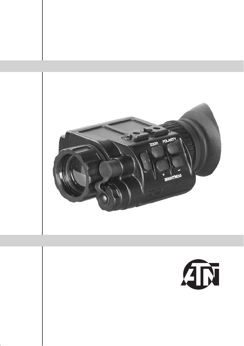
OTIS-14
user`s guide
Important Export Restrictions! Commodities, products, t ec hn ol og ie s a nd se rv ic es co nt ai ne d in th is ma nu al
are subject to one or more of the export control laws and
r e gu l a ti o n s o f t he U .S . G ov e r nm e n t a n d th e y f a l l u n d e r t h e
control jurisdiction of either the US Department of State
or the US BIS -Department of Commerce. It is unlawful
and str ictly prohi bited to ex port, or attempt to expor t or
otherwise transfer or sell any hardware or technical data
or furnish any service to any foreign person, whether
abro ad or in the Un it ed St ates, f or wh ic h a license o r w ri tte n a ppr oval o f t he U.S. G overn men t i s re quire d, wit hou t
first obtaining the required license or written approval
from the Department of the U.S. Government having
jurisdiction. Diversion contrary to U.S. law is prohibited.
AMERICAN
TECHNOLOGIES
NETWORK
CORP.
Page 2
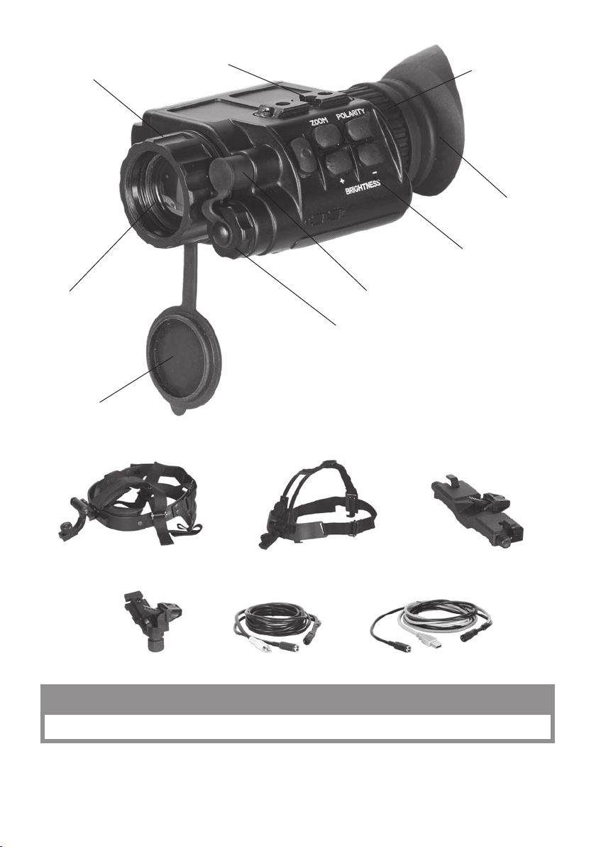
Focusing Ring
Mounting Rail
Eyepiece Diopter
Adjustment Ring
Rubber Eyecup
Switchboard
Lens
Ob ject ive Lens Cove r
Head Mount Helmet Mount Dual Bridge
Adapter
Universal Connector Unit
Battery Compartment Cover
Video Cable PC Cable
CAUTION:
Th is pro du cT con Tai ns n aTu ral rub ber laTe x w hic h m ay cau se all er gic re acT io ns
The information in this manual furnished for information use only, is subject to change without notice, is not to be
co nst rue d as a c om mit men t by AT N Co rp.
ATN Co rp. as sum es n o r esp ons ibi li ty o r li ab ili ty f or any er ro rs o r i nac cur aci es tha t m ay app ear in th is b oo k.
©2009 ATN Corp. All right reserved.
Page 3

f e a t u r e s
• H igh re sol uti on d igi tal th erm al ima gin g
• C omp act , li ght we igh t a nd d ur abl e hous ing
• H ead /hel met mou nt abl e for h and s free usa ge
• H igh Qua lit y opti cs
• V ide o a nd c omp ute r o utp ut
• V ide o /Image pol ari ty s ele cti on
• Water pro of
spec ifi cat io n
Magnification ........................................................1,8X
Objective Focal Length ........................................25 m m
FOV ......................................................................11° x 8 °
Focus Range ........................................................f rom 1m t o infi nit y
Focus Adjustment ................................................Manual
Exit Pupil ..............................................................14mm
Eye Relief .............................................................25mm
Det ec tor Typ e ....................................................... Uncooled Microbolometer
Spectral Response...............................................7-14 μ m
Pixels ....................................................................160 x 120
Pixel Size ..............................................................30 x 30 μm
Angular Resolution, mrad ....................................1,2
Thermal Sensitivity ..............................................< 0,1°C
Ra nge to Detec t a Hum an ....................................475 m
Output Format ......................................................Analog PAL / NTSC
Display .................................................................OLED matrix
Display Format .....................................................SVGA , 852 x 600 px l
Color .....................................................................Monochrome
Digital ZOOM .......................................................Fixe d 2x (op tio nal 5x)
Brightness Adjustment .........................................Manual
Contrast Adjustment ............................................Automatic
Available User Interfaces .....................................Fro m ou tsi de PC t hro ugh US B inte r fa ce
Power Supply .......................................................2 x 3 V, 12 3At ype
Start-Up Time .......................................................< 3 sec
Op erati ng T ime w/on e b att ery pac k .....................4 h rs
Ex ter nal Powe r S upp ly .........................................DC 6V, 50 0 mA
Operating Temperature Range ............................fro m -20° C to +50 °C
Waterproof ...........................................................Yes, u p t o 10m sub mer sio n
Dimensions ..........................................................118 x 78 x 54 mm
Weight (w/batteries) .............................................0,34 kg
* ATN reserves the right to change the above specifications at any time without notice
a p p l i c a t i o n
The O TI S-14 i s a th er ma l s yste m i nt en de d f or law en fo rc em en t, mil it ar y a nd co mm er ci al us es . I t is b ui lt
ar ound s tate of t he art u ncool ed the rm al i magin g te ch nolo gy, highl y int egra ted D SP- ba sed e lectr on ics
an d a com pac t, lig ht wei ght sy stem.
The OTIS-14 thermal monocular provides the excellent image quality that is unaffected by lights or
shadows that ser iously hamper the imag e quality of image intensified night vision. Total darkness,
camouflage or bright lights will not affect the sensitivity of these units.
The included and optional accessories provide for the versatility of the monocular. You can put it on a
he ads et or o n a hel met , c onn ect ed t o a not her mo noc ula r t o bu il d a bin ocu lar sy stem e tc .
The ATN OTIS -14’s supe ri or per fo rm ance, compact size, comfort of wear an d cost ef fi ci ency makes i t
the perfect thermal imaging device.
2
Page 4

3
o p e r a t i o n
Insert the two Lithium batt er ie s (12 3A ty pe ) i nto the u ni t acc or ding to the polarity indications on the battery compar tment. Press
the ON /OFF button to turn the monocular on. Remove the lens
cap.
Ad jus t t he p ro per ey epi ece dio pter a nd obj ect ive le ns foc usi ng.
The rotation of the Focusing Ring changes the position of the
objective lens in respect of the receiver focal plane array. In this
way t he o per ato r c an a dju st t he u nit in o rde r to se e th e ta rge ts a t
various ranges with the same good contrast.
Cover protects the objective assembly from mechanical damage.
The operator can ad just th e eye piece diopter of the mono cular for his/her own eye sight by rotating
Eyepiece Diopter Adjustment Ring.
Eyecup provid es for the com for tabl e eye posit ion and for the prevention of fl ash refle ctions onto the
op erato r’s fa ce whi ch i s c rit ica l in th e f iel d an d t act ica l ac tiv iti es.
Sel ect th e desired operatio n mode by pressing the switchboard
buttons.
With the «ZOO M» bu tton you c an activate a g ra du al ad justment
of th e di git al zoo m pres et in t he mon ocu lar ad jus tme nts .
The «POLARITY» button switches the direct display mode into
the reverse one, i.e. from hot-white /cold -black into hot-black /
cold-white mode.
Ea ch s hor t pu sh of t he b utt ons «B RIG HTN ES S +» or «BR IGH TNESS –» raises or lowers the display brightness, correspondin gly, in ste pwi se way.
To turn the monocular off press the ON/OFF button.
s e t t i n g
The working settings of this thermal monocular may be customized by means of a PC.
In sta ll t he s oft war e in to t he PC f rom the CD/DVD s upp lie d in the
package of each OTIS-14 unit. Connect the monocular to the PC
through th e included US B cable. Th e USB Cab le is an i nterface
lin k between the thermal mon oc ular and the external PC, and it
ac cep ts t he ext ern al p ow er sup ply at the sa me tim e.
IMPORTANT: Wh en the uni t is to b e powered with extern al
so urc es, fi rst make s ure the bat ter ies have b een tak en out.
Th e the rma l mon ocul ar O TIS -14 can be p owe red e ith er f rom the
inc luded batteries or from any ex terna l source. Switch the mo no cul ar on, sta rt t he aux ili ary sof twa re and intro duc e all t he n eed ed o r d esi rab le set tin gs i nt o it.
USB Connec tor
Exter nal Power
Supply Connector
v i d e o o u t p u t
The monocular incorpor ate s a sealed Conne ctor used for video
transmission and to co nn ec t ext er na l power s ou rc es . The package of the thermal monocular OTIS-14 includes external connect io n V id eo Ca bl e. Vid eo Ca bl e at ta ch es the mo no cu la r to t he
video facilities for video recording or video transmission to the
external display, though at the same time it accepts the external
power supply.
IMPORTANT: Wh en the unit is to b e powered with external
so urc es, fi rst make s ure the bat ter ies have b een tak en out.
Video Connector
Exter nal Power
Supply Connector
Page 5

4
h e a d m o u n t (o p t i o n a l )
The operator can mount the monocular onto the head bracket
using any of two Mounting Rail located on the op posite sides
of the body, to be ab le to se e through the eyepiece with his /h er
ri ght or lef t eye cor res pon din gly.
To mou nt the OT IS-14 to a he adm oun t, per for m the f oll ow ing :
1. Loose n t he sc rew ( A) . P ush th e b ut to n ( B) an d ins er t t he ra il of
th e OTI S-14 i nto th e so cket ( C) o f t he hea dse t.
2. Pl ace th e he ad mou nt wit h OTIS -14 on to a h ead .
3. Loosen the scr ew (A) and move the unit al ong the rail for eye
relief adjustment.
4. The OTIS-14 head mount has a flip-up mechanism. Pus h the
but ton (D) on th e side of mount an d lift the unit up until the unit
fi xates in the top pos iti on.
5. Pu sh the sam e bu tto n (D ) to lo we r OTI S-14 t o t he v ie win g p osi tio n.
6. T he OTIS-14 c an be placed o nto the r ig ht or l ef t eye. In o rd er to readjust th e monocular f or use wi th
the o th er eye, ta ke th e u nit of f t he ad ap te r, t ur n t he un it to o th er si de (f or 18 0º ) an d m ou nt it on th e head mount adapter through the rail on this side. Push the button (E) and move the device along the slide-rail
(F ) for c omfor tabl e p osi tio n.
D
B
A
C
F
E
h e l m e n t m o u n t (o p t i o n a l )
Attachment of OTIS-14 to a standard PASGT helmet. The Helmet mount fits securely onto helmet
via a rugged strapping device and grooved hooks. With helmet
mount, the OTIS-14 can be positioned directly in front of user’s
eyes or fli ppe d u p ou t o f view ing pos iti on.
1. I nst all th e mo unt on to hel met as sho wn on t he p ict ure.
2. Tig hten a nd fix ate th e s tra ps (A)
3. At tac h th e m ono cul ar to t he rai l.
4. Loosen s crew (C). Push b utton (B ) and insert the bracket of
th e OTI S-14 i nto ra il ( D) o f t he h elm et mou nt.
5. Pl ace th e helm et wit h OTIS -14 on to hea d.
6. Loosen the screw (C) and move the unit for proper eye relief
adjustment.
7. T he OT IS -14 h el me t m ou nt ha s a fl ip -up m ec ha ni sm . P us h t he
bu t to n (E ) o n th e s ide of mou nt and lif t the u nit up unt il the uni t f ixate s in th e top p osi tio n.
8. Pu sh t he sam e b utt on ( E) to l ow er OT IS-14 to vie win g p osi tio n.
9. The OTIS-14 can b e placed on to the ri ght or left eye. In order to readj us t the m on oc ul ar for use wi th
th e oth er eye, take the unit off t he he admo unt a dapt er, tu rn t he un it to oth er si de (f or 180º) a nd mo unt i t
on the adapter through the rail on this side. Push the button (E) and move the device along the slide-rail
(F ) for c omfor tabl e p osi tio n.
E
B
C
D
A
F
A
e x t e r n a l p o w e r s o u r c e
IM PO RTANT: Whe n t he uni t i s to be po we re d with ex te rna l s ource s, fir st make sure t he bat te rie s h ave
been taken out.
To connect an ex ternal power source you can us e any of the cable s of the monocular package. As an
external power source, a standard network controller with outer voltage of 6V and current of over 0.5A
ca n be ap pli ed.
Remove the protective cover off the connector input and at tach the cable. To connect an external
so urc e, we rec omm end yo u to us e a 6mm st and ard do ubl e-p ole so cke t i n the w ay th e po si tive c ont act
is the central contact.
Page 6

5
w a r n i n g s a n d c a u t i o n s
IMPORTANT!
DO NOT DISASSEMBLE THE MONOCULAR.
KE EP YOU R O TIS -14 S AFE FR OM O PE RATIO NAL AND TRA NSP ORTAT ION I MPAC TS.
WAITING FOR O NE HOU R BEFORE YOU SW IT CH THE MONOCUL AR ON I S HIGHLY RECOM-
ME NDABL E AF TER YO U B RIN G IT INT O TH E WAR M ROOM FRO M TH E C OLD ER O UTS IDE .
WHEN YOU DO NOT INTEND TO OPERATE YOUR MONOCULAR FOR 10 FOLLOWING DAYS WE
AD VIS E YOU TO TAKE THE BATTE RY OUT OF T HE BATTE RY COM PART MEN T.
PROVIDE FOR TIMELY SERVICE MAINTENANCE OF THE UNIT.
If you use the rubber eyecaps for a long period of time, you may suffer skin inflammation. If you develop
an y s ymp tom s, con sul t a doc tor im med iatel y.
t r o u b l e s h o o t i n g
Q: Th e imag e is ab sent o n the s cre en of g ogg les.
S: The batteries are discharged. Replace the batteries.
Q: Th e brig htn ess of the image on t he s cre en is l ow.
S: Th e b att eri es has a low vol tag e. Rep lac e t he bat ter ies .
Page 7

6
1 y e a r p r o d u c t w a r r a n t y
This product is guaranteed to be free from manufacturing defects in material and workmanship under
normal use for a period of 1 (one) years from the date of purchase. In the event a defect that is covered
by the foregoing warranty occurs during the applicable period stated above, ATN, at its option, will eith er r epai r or rep lace the pro duct, and suc h act ion o n th e pa rt of ATN s hal l be the f ull ext ent of AT N’s liability, and the Customer’s sole and exclusive remedy. This warranty does not cover a product (a) used
in other th an its normal and custo mary manner ; (b) subjec ted to misuse ; (c) s ubjec ted to alteratio ns,
modifications or repairs by the Customer of by any party other than ATN without prior written consent of
ATN; (d) special order or “close-out” merchandise or merchandise sold “as-is” by either ATN or the ATN
dealer; or (e) merchandise that has been discontinued by the manufacturer and either parts or replace men t u nits a re not avai la bl e due to rea so ns bey on d the co ntrol of ATN. AT N s hall n ot be r es po nsibl e f or
any defects or damage that in ATN’s opinion is a result from the mishandling, abuse, misuse, improper
storage or im proper operati on, including use in conjun ction with equipment whic h is electrically or
mechanically incompatible with or of inferior quality to the product, as well as failure to maintain the environmental conditions specified by the manufacturer. CU ST OM ER IS HE RE BY NO TI FI ED TH AT O P-
ERAT IO N O F T HE EQ UI PM EN T D UR ING D AYL IGHT H OU RS O R U ND ER AN Y E XC ES SI VE L IG HT
CONDITIONS MAY PERMANENTLY DAMAGE THE INTERNAL COMPONENTS OF THE UNIT AND
SAID D AM AG E W IL L N OT BE C OV ER ED UN DE R T HI S W AR RA NT Y. This warranty is extended only
to the o ri gina l pur ch aser. A ny br each o f thi s war ranty s hall b e wa ived u nless the c us tome r not if ies ATN
at the address noted below within the applicable warranty period.
The c ustomer understands and agrees that except for the foregoing warrant y, no other warranties
wri tten or or al, statutor y, expre ssed or im plied, including any imp lied warrant y of merchantability or
fitness for a particular purpose, shall apply to the product. All such implied warranties are hereby and
expressly disclaimed.
Limitation of liability
ATN will not be li able for any claims, actio ns, suits, proceedings, costs , expenses, d amages or lia bili-
tie s a risin g o ut of th e use of this pr oduct. Op er atio n a nd us e o f the pr oduct a re the s ol e res po ns ibili ty of
the Customer. ATN’s sole undertaking is limited to providing the products and services outlined herein
in accordanc e with the terms and condition s of this Agreement. The provision of prod ucts sold and
ser vices pe rformed by ATN to th e Cu stomer shall not be interpreted, construed, or regarded, eit her
ex pr essly or im pl ie d, a s b eing for t he benef it of or cre at ing a ny ob li gatio n t owa rd any thir d p ar ty of le gal
entity outside ATN a nd t he Customer; ATN’s oblig ations under this Agreement extend solely to the
Customer. ATN’s li ability he reund er for dama ges, r eg ardle ss of the form or ac ti on, shal l not ex-
ceed th e f ees or ot he r c ha rg es pa id to AT N by t he c us to me r o r c us to me r’s d ea le r. ATN sh al l n ot ,
in a ny ev en t, be li ab le for s pe cia l, in di re ct , i nc id ent al, or co ns eq ue nt ia l d am ag es , i nc lu di ng , b ut
not l im it ed to , lost in co me , l os t r evenue, o r l os t p ro fi t, wh et he r s uc h damages w er e f or es ee ab le
or not at th e time of purchase, and whether or n ot s uch damages arise out of a bre ach of war ra nty, a br eac h of ag ree men t, n egl ige nce , st ric t l iab ili ty o r a ny oth er t heo r y o f liab ility.
Product warranty registration
In ord er to validate the warranty on your product, ATN must receive a completed Product Warranty
Registration Card for each unit or complete warranty registration on our website at www.atncorp.com.
Please complete the included form and immediately mail it to our Service Center: ATN Corporation,
1341 San Mateo Aven ue, So uth Sa n Fran cis co, CA 94 080 .
Obtaining warranty service
11092008
To o btai n wa rran ty se rv ice on yo ur u nit , ple ase c onta ct ou r Cu stom er S er vic e depa rtmen t an d req uest
an R MA nu mb er. On ce you ha ve r ec ei ve d your RM A # plea se ma rk this # o n t he ou ts id e o f the s hi pp in g
box and take or send the product, postage paid, with a copy of your sales receipt to our service center,
ATN Corporation at the address n ote d above. All merchan dise must be full y insured wit h the correct
pos ta ge ; ATN w ill no t be r es po nsib le for im prope r post ag e or m is sing o r dama ge d mer ch andise durin g
shi pment . Packages th at d o not have an RMA # clearly marke d on the outside of the package will b e
delayed in being processedt.
Page 8

For customer service and technical support, please contact
1341 San Mateo Avenue, Sout h San Fran cis c o, CA 9408 0
American Technologies Network Corp.
North American Office
Toll Free Phone: 800-910-2862
Phone: 650-989-5100; fax: 650-875-0129
www.atncorp.com
©2009 ATN Corporation
 Loading...