

Page 1
ATN ODIN
THERMAL MULTI-PURPOSE SYSTEM
operator’s manual
Important Export Restrictions! Commodities, products,
technologies and services contained in this manual are
subject to one or more of the export control laws and
regulations of the U.S. Government and they fall under the
control jurisdiction of either the US Department of State
or the US BIS-Department of Commerce. It is unlawful
and strictly prohibited to export, or attempt to export or
otherwise transfer or sell any hardware or technical data or
furnish any service to any foreign person, whether abroad
or in the United States, for which a license or written
approval of the U.S. Government is required, without
first obtaining the required license or written approval
from the Department of the U.S. Government having
jurisdiction. Diversion contrary to U.S. law is prohibited.
OPERATOR’S MANUAL (ODIN) REVISION 1 – MARCH 2013
Page 2

Register your product warranty online at
www.atncorp.com/warranty
Manual (Odin) Revision 1 - MARCH, 2013
The information in this manual furnished for information use only, is subject to
change without notice, is not to be construed as a commitment by ATN Corp.
ATN Corp. assumes no responsibility or liability for any errors or inaccuracies that may appear in this book.
© 2013 ATN Corp. All right reserved.
Page 3

SAFETY SUMMARY
STUDY CAREFULLY THIS MANUAL BEFORE TURNING ON
AND OPERATING THIS PRODUCT.
CAUTIONS
The ATN Odin thermal multi-purpose system are precision
optical-electronic instruments and requires careful handling.
To provide safe use of the systems the following instructions
should be observed:
• Do not dismantle the device.
• Keep the device clean; protect it from moisture, sharp temperature drops and shocks.
• Be careful not to touch the glass surfaces. If you put fingerprints on, or contaminate the glass surfaces, use only clean
and soft materials to clean it.
•
Do not leave the device in on position during stops in operation.
• Remove the battery from the device for the period of storage.
CAUTION:
THIS PRODUCT CONTAINS NATURAL RUBBER
LATEX WHICH MAY CAUSE ALLERGIC REACTIONS
a
Page 4

WARNING
Do not permanently attach the device to dynamic-mount applications that continuously transmit vibration (such as on vehicles or
heavy machinery).
WARNING
Do not point the monocular directly at any high-intensity objects
that you must not view with your eyes (such as the sun or a welding arc). If you do, you will damage the camera.
WARNING
Operating Odin outside of its specified operating temperature
range or voltage range can cause permanent damage and will
void the warranty.
WARNING
Use the power switch to turn the camera off before you remove
power (remove battery).
WARNING
Do not use any battery other than a CR-123A lithium battery. DO
NOT use any battery(ies) providing a (combined) voltage greater
than 3.0 volts.
WARNING
Do not replace battery in a possibly explosive environment, such
as a gas station (or any place where you must turn off your vehicle
engine). If you do, sparks can cause an explosion.
WARNING
Remove the battery before you store the camera for extended
periods (2 weeks or more).
WARNING
Do not carry battery in pockets containing metal objects such as
coins, keys, etc. Metal objects can cause the battery to short circuit and become very hot. In the case of lithium batteries, a short
circuit could cause them to explode.
WARNING
Observe battery manufacturer’s guidelines for safe handling and
proper disposal of batteries.
b
Page 5

NOTE
Please be aware that the most common problem that first time
users of Thermal products encounter is improper utilization of
Calibrate/NUC function. The first step before using the product
should be to properly calibrate the device. To do this please turn
the unit on, close the objective lens with the lens cap and press
the Calibrate/NUC function either as described in 3.2.2.3 or by
holding down both the UP and DOWN buttons at the same time.
Please carefully read 3.2.2.3 as to additional information on Calibration/NUC function.
EQUIPMENT LIMITATIONS
• The Odin detector spectral band (7 to 14 µm) provides a better
penetration through smoke, smog, dust, water vapor etc.
• Infrared radiation does not travel through glass and therefore
the monocular does not sense objects if they are behind a glass
window.
c
Page 6

TABLE OF CONTENTS
pg.
CHAPTER 1. INTRODUCTION ........................1-1
1.1 General Information ...........................1-2
1.1.1. Scope ....................................1-2
1.1.2. Repor ts ...................................1-2
1.1.3. Storage ...................................1-2
1.1.4. Warranty Information ........................1-2
1.2. Equipment Description .........................1-5
1.2.1. Equipment characteristics, capabilities
and features ...............................1-5
1.2.2. Location and description of major components ....1-6
1.2.3. Specifications ..............................1-9
1.2.4. Mechanical Functions .......................1-11
1.2.5. Optical Functions ..........................1-11
1.2.6. Electrical Function .........................1-12
CHAPTER 2. ASSEMBLY AND PREPARATION ...........2-1
2.1. Preparation ..................................2-2
2.1.1. Preparation for use ..........................2-2
2.1.2. Installation of eyecup ........................2-3
2.1.3. Installation of demist shield ....................2-3
2.1.4. Installation and adjustment of headmount ........2-4
2.1.5. Installation of headmount/helmet mount adapter ...2-5
2.1.6. Installation of helmet mount to helmet. . . . . . . . . . . . 2-6
2.1.7. Installation of headmount with protective mask ....2-8
2.1.8. Installation of weapon mount ..................2-9
CHAPTER 3. OPERATION ............................3-1
3.1. General Information ...........................3-2
3.1.1. General ...................................3-2
3.1.2. Controls and Indication .......................3-2
3.2. Operating procedure ..........................3-4
3.2.1. Turning On ................................3-4
3.2.2. Menu sets .................................3-4
i
Page 7

3.2.3. Hand-held operation ........................3-11
3.2.4. Head mounted operation ....................3-11
3.2.5. Helmet mounted operation ...................3-13
3.2.6. Weapon mounted operation ..................3-15
3.2.7. Preparation for storage ......................3-16
CHAPTER 4. MAINTENANCE INSTRUCTIONS ...........4-1
4.1. Lubrication Instructions ........................4-2
4.2. Troubleshooting procedures ....................4-2
4.2.1. Troubleshooting ............................4-2
4.3. Operator’s Maintenance Procedures .............4-5
4.3.1. Cleaning the scope ..........................4-5
4.3.2. Headmount Maintenance .....................4-5
4.3.3. Neck cord maintenance ......................4-7
ii
Page 8

HOW TO USE THIS MANUAL
• Usage
You must familiarize yourself with the entire manual before operating the equipment. Read and follow all warning notices.
• Manual Overview
The table of contents includes the paragraph number, paragraph
title, and page number.
iii
Page 9

CHAPTER 1
INTRODUCTION
1-1
Page 10

1.1 GENERAL INFORMATION
1.1.1. SCOPE
This manual contains instructions for use in operating and maintaining the ATN Odin thermal multi-purpose systems. Throughout
this manual, the ATN Odin will be referred to as the scope or Odin.
1.1.2. REPORTS
Reports from the user on recommendations for improvements are
encouraged. Send reports to the address below.
American Technologies Network Corp.
1341 San Mateo Avenue
South San Francisco, CA 94080
(800) 910-2862
(650) 989-5100
(650) 875-0129 fax
info@atncorp.com
www.atncorp.com
1.1.3. STORAGE
Storage of Odin should be done in the factory packing and after a
thorough PMCS as outlined in Section 4.1. of this manual. This will
ensure the scope remains in mission ready condition during storage. Battery should be stored separately from the scope.
The scope should not be placed on the floor, in any area exposed to
high temperatures or direct sunlight. Presence of acid and alkaline
vapor, as well as of other aggressive admixtures in the air is unacceptable.
1.1.4. WARRANTY INFORMATION
ONE YEAR PRODUCT WARRANTY
This product is guaranteed to be free from manufacturing defects in material
and workmanship under normal use for a period of 1 (one) years from the date
of purchase. In the event a defect that is covered by the foregoing warranty
occurs during the applicable period stated above, ATN, at its option, will either
repair or replace the product, and such action on the part of ATN shall be the
full extent of ATN’s liability, and the Customer’s sole and exclusive remedy.
1-2
Page 11

This warranty does not cover a product (a) used in other than its normal and
customary manner; (b) subjected to misuse; (c) subjected to alterations, modifications or repairs by the Customer of by any party other than ATN without
prior written consent of ATN; (d) special order or “close-out” merchandise or
merchandise sold “as-is” by either ATN or the ATN dealer; or (e) merchandise
that has been discontinued by the manufacturer and either parts or replacement units are not available due to reasons beyond the control of ATN. ATN
shall not be responsible for any defects or damage that in ATN’s opinion is
a result from the mishandling, abuse, misuse, improper storage or improper
operation, including use in conjunction with equipment which is electrically
or mechanically incompatible with or of inferior quality to the product, as well
as failure to maintain the environmental conditions specified by the manufacturer. This warranty is extended only to the original purchaser. Any breach of
this warranty shall be waived unless the customer notifies ATN at the address
noted below within the applicable warranty period.
The customer understands and agrees that except for the foregoing warranty,
no other warranties written or oral, statutory, expressed or implied, including
any implied warranty of merchantability or fitness for a particular purpose,
shall apply to the product. All such implied warranties are hereby and express-
ly disclaimed.
LIMITATION OF LIABILITY
ATN will not be liable for any claims, actions, suits, proceedings, costs,
expenses, damages or liabilities arising out of the use of this product. Operation and use of the product are the sole responsibility of the Customer.
ATN’s sole undertaking is limited to providing the products and services
outlined herein in accordance with the terms and conditions of this Agreement. The provision of products sold and services performed by ATN to
the Customer shall not be interpreted, construed, or regarded, either expressly or implied, as being for the benefit of or creating any obligation
toward any third party of legal entity outside ATN and the Customer; ATN’s
obligations under this Agreement extend solely to the Customer. ATN’s li-
ability hereunder for damages, regardless of the form or action, shall
not exceed the fees or other charges paid to ATN by the customer or
customer’s dealer. ATN shall not, in any event, be liable for special,
indirect, incidental, or consequential damages, including, but not
limited to, lost income, lost revenue, or lost profit, whether such damages were foreseeable or not at the time of purchase, and whether
or not such damages arise out of a breach of warranty, a breach of
agreement, negligence, strict liability or any other theory of liability.
1-3
Page 12

PRODUCT WARRANTY REGISTRATION
In order to validate the warranty on your product, ATN must receive a
completed Product Warranty Registration Card for each unit or complete
warranty registration on our website at www.atncorp.com. Please complete the included form and immediately mail it to our Service Center: ATN
Corporation, 1341 San Mateo Avenue, South San Francisco, CA 94080.
OBTAINING WARRANTY SERVICE
To obtain warranty service on your unit, End-user must notify ATN service department by calling 800-910-2862 or 650-989-5100 or via e-mail
service@atncorp.com to receive a Return Merchandise Authorization
number (RMA). When returning please take or send the product, postage
paid, with a copy of your sales receipt to our service center, ATN Corporation at the address noted above. All merchandise must be fully insured
with the correct postage; ATN will not be responsible for improper postage or, missing or damaged merchandise during shipment. When sending
product back, please clearly mark the RMA# on the outside of the shipping box. Please include a letter that indicates your RMA#, Name, Return
Address, reason for service return, Contact information such as valid telephone numbers and/or e-mail address and proof of purchases that will help
us to establish the valid start date of the warranty. Product merchandise
returns that do not have an RMA listed may be refused or a significant delay in processing may occur. Estimated Warranty service time is
10-20 business days. End-user/customer is responsible for postage to
ATN for warranty service. ATN will cover return postage/shipping after
warranty repair to end-user/customer only if product is covered by aforementioned warranty. ATN will return product after warranty service by domestic UPS ground and/or domestic mail. Any other requested, required
or international shipping method the postage/shipping fee will be the responsibility of the end-user/customer.
1-4
Page 13

1.2 EQUIPMENT DESCRIPTION
1.2.1. EQUIPMENT CHARACTERISTICS,
CAPABILITIES AND FEATURES
The Odin Series is one of the smallest Thermal Imaging Monocular Systems today. It features extremely small size and low weight
because of its advanced construction and characteristics using the
latest technologies in high grade polymers to make a Mil. Spec,
system that is identical in size, weight and shape to a AN/PVS-14.
The Odin series is a multi-purpose system using the latest in miniature thermal sensor technology combined with an advanced OLED
Display to provide a superior stable image in a compact and rugged
package. The system also includes an array of features that help
the user to enhance the sight to meet all of their requirements.
The Odin system is designed for hand held, head mounted and
weapon mounted operations. It uses most of the same accessories
as the AN/PVS-14 Night Vision Monocular System.
The Odin is one of the most capable thermal monocular systems
on the market.
The Odin-W Series has the ability to be rail mounted to a light caliber weapon such as a M16 or M4 using the accessory weapon rail
interface adapter.
As with the standard Odin series has the With the ability to use
most accessories for the AN/PVS-14 with the added benefit to be
weapon mounted as well. The Odin-W is user friendly and easy to
learn to use. The system design has been proven effective and reliable as well as functional. The Odin-W is a perfect complement to
any user of night vision monocular systems.
1-5
Page 14
1.2.2. LOCATION AND DESCRIPTION
OF MAJOR COMPONENTS
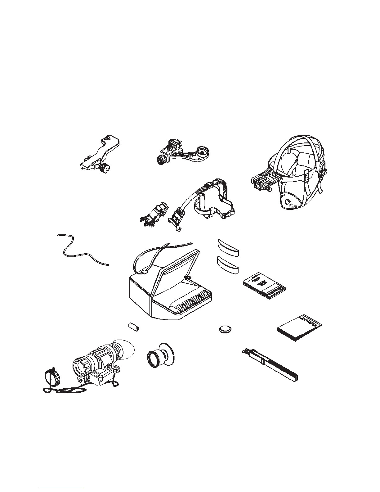
Included and optional items are shown in Figure 1.1. The major
components are the headmount, helmet mount, monocular, carrying case, and the shipping and storage case.
WEAPON MOUNT
(OPTIONAL)
NECK CORD
BATTERY
HEAD/HELMET MOUNT
HELMET MOUNT
(OPTIONAL)
CARRYING
CASE
ADAPTER
BROWPAD
MEDIUM
AND THICK
BROWPADS
DEMIST
SHIELD
HEADMOUNT
THIN
OPERATOR ’S
MANUAL
LENS
CLEANING
CLOTH
OBJECTIVE
LENS CAP
MONOCULAR
FIGURE 1.1. COMPONENTS OF ODIN
1-6
EYEGUARD
CARRYING
CASE STRAP
Page 15
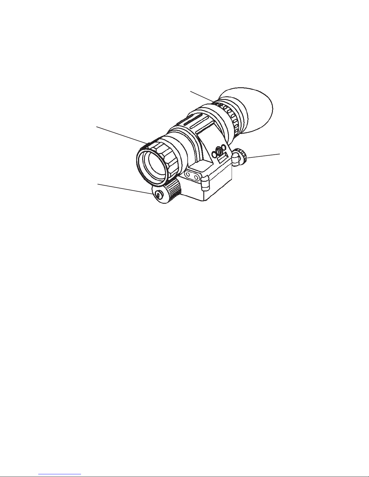
a. Monocular
The monocular (see Figure 1.2.) consists of various components
such as an objective lens, a thermal core (not shown), an eyepiece
lens and a battery cap.
EYEPIECE
LENS
OBJECTIVE
LENS
ON-OFF
SWITCH
BATTERY
CAP
FIGURE 1.2. MULTI-PURPOSE THERMAL SYSTEM
The monocular also uses the accessories listed below:
Demist Shield – The demist shield (Figure 1.1.) is used to
prevent the eyepiece lenses from becoming fogged.
Sacrificial Window – Please note the PVS14 sacrificial window
will not work with the Odin. Do not attempt to use will not get an
image.
b. Headmount
The headmount (Figure 1.1.) secures the monocular to the operator’s head for night viewing and provides freehand support for use
with a weapon, protective mask or other purposes. It is adjustable
and cushioned. The thin browpad used for large heads, comes attached to the headmount; the thick and medium browpads, used for
smaller heads are stored in the carrying case.
c. Helmet Mount
This item (Figure 1.1.), secures the monocular to the Personal Armor System Ground Troops (PASGT) helmet allowing freehand
support for use with a weapon, protective mask and/or other purposes. The new helmet mount is made of a ruggedized metal. The
old one is made of plastic.
1-7
Page 16

d. Headmount/Helmet Mount Adapter
This item (Figure 1.1.) is attached to the monocular to allow its use
with the headmount or helmet mount. It allows mounting in front of
the left or right eye.
e. Weapon Mount
The weapon mount (Figure 1.1.) adapts the monocular to the receiver rail as configured for the modular weapon system kit.
f. Carrying Case
The carrying case (Figure 1.1.) is provided for transportation and
protection of the monocular, headmount, battery and accessories. Two slide keepers are provided for belt attachment and three
D-rings for shoulder and leg strap attachment. A carrying case
strap is also provided which can be attached to the two D-rings on
the back of the carrying case.
1-8
Page 17
ODIN- 61B
ODIN- 61BW
ODIN-6WB
ODIN-6WBW
ODIN-32D
ODIN-32DW
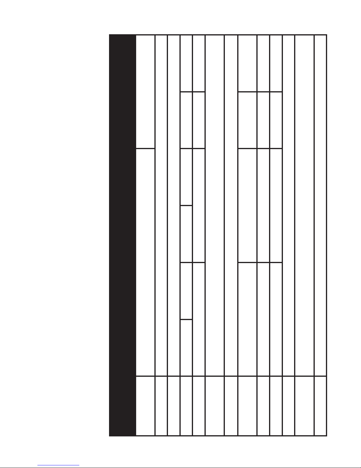
Table 1-1. Specifications
Uncooled
7-14 µm
17 µm
27 mm
-6 to +4
0.25 m to infinity
ODIN-32C
ODIN-32CW
Vanadium oxide (VOx)
320 x 240 px 640 x 480 px
ODIN-31D
ODIN-31DW
1x 2x 0.5x 1x
17 mm 35 mm 17 mm 35 mm
2x, 4x 4x, 8x 1x, 2x, 4x 2x, 4x, 8x
24° x 18° 15° x 11° 48° x 36° 24° x 18°
30 Hz 60 Hz 30 Hz 60 Hz 30 Hz 30 Hz
ODIN-31C
ODIN-31CW
1.2.3. SPECIFICATIONS
The following tables provide information pertaining to the operational, electrical, mechanical,
optical and environmental characteristics for the monocular.
ITEM
Sensor (micro-
bolometer)
Type
Material
Frame Rate
Pixel Size
Spectral
Response
Pixel Size
Optical
Magnification
E-Zoom
FOV
Focus Range
Diopter
Adjustment
Eye Relief
1-9
Page 18

only
ODIN- 61B
ODIN- 61BW
ODIN-61BW
only
ODIN-6WB
ODIN-6WBW
ODIN-6WBW
only
ODIN-32D
ODIN-32DW
ODIN-32DW
<4 s
800 x 600 px
>2 hrs
0.77 lb /0.35 kg
only
ODIN-32C
ODIN-32CW
ODIN-32CW
Waterproof / Dustproof
1 x 3V, CR123A Lithium battery type
White hot / Black hot / Multiple Color Modes
3.40” x 2.20” x 1.95” / 87 mm x 56 mm x 50 mm
only
ODIN-31D
ODIN-31DW
500 m 750 m 500 m 750 m
225 m 300 m 225 m 300 m
135 m 180 m 135 m 180 m
1100 m 1650 m 550 m 1650 m
495 m 660 m 495 m 660 m
300 m 400 m 300 m 400 m
ODIN-31DW
only
ODIN-31C
ODIN-31CW
ODIN-31CW
ITEM
Human
Detection
Human
Recognition
Human
Identification
1-10
Vehicle
Detection
Vehicle
Recognition
Vehicle
Identification
Multiple
Reticles to
Choose From
Image Size
(output
resolution)
Polarity control
Start up time
Waterproof
Battery type
Battery Life
Dimensions
Weight
* ATN reserves the right to change the above specifications at any time without notice
Page 19

1.2.4. MECHANICAL FUNCTION
The mechanical adjustments of the Odin sights allow for physical
differences between individual operators using the system. The
scope functions include the ON-OFF switch, UP button, ENTER
button, DOWN button, video-out, eyepiece diopter adjustment ring,
battery compartment cover, mounting thread. The mechanical controls are identified in Figure 1.3.
MOUNTING THREAD
FRONT LENS
AS SE M BLY /
VARIABLE PIVOT
TECHNOLOGY
BATTERY CAP
EYEPIECE DIOPTER
ADJUSTMENT RING
DOWN BUTTON
ENTER BUTTON
UP BUTTON
RUBBER
EYECUP
ON-OFF SWITCH
VIDEO-OUT
FIGURE 1.3. MECHANICAL CONTROLS
1.2.5. OPTICAL FUNCTIONS
The optical functions include an objective lens, thermal imaging
detector and eyepiece. Infrared energy is emitted proportionally
to the temperature of an object. The warmer the object, the more
energy it emits. The infrared energy from the objects is focused by
the optics, onto an infrared detector. The information from infrared
detector is passed to electronics for image processing. The signal
processing circuitry translates the infrared detector data into an image that can be viewed on the built-in OLED display. The image is
observed through an eyepiece by operator.
1-11
Page 20

1.2.6. ELECTRICAL FUNCTION
The electronic circuit is powered by replaceable battery – one 3 V
Lithium battery (CR123A type battery).
Power from the battery is supplied to the components through the
OFF-ON switch.
1-12
Page 21

CHAPTER 2
ASSEMBLY AND PREPARATION
2-1
Page 22

2.1. PREPARATIONS
2.1.1. PREPARATION FOR USE
This chapter contains the information necessary to prepare the
scope for operation. This includes unpacking, examination for
damage, and battery installation.
A. UNPACKING
The following steps must be accomplished prior to each mission
where the sight is used.
1. Open carrying case, remove the scope and check contents
for completeness.
2. Inspect the scope for obvious evidence of damage to optical surfaces, body, eyecups, operation buttons, etc. Ensure
that all optical surfaces are clean and ready for use. Clean
with lens paper.
B. ATTACHMENT OF NECK LANYARD
To prevent damage due to dropping the scope, use the neck lanyard included with your equipment.
C. INSTALLATION OF BATTERY
WARNING
The lithium battery contains sulphur dioxide gas under pressure.
Do not heat, puncture, disassemble, short circuit, attempt to
recharge or otherwise tamper with the batteries.
Turn off equipment if battery compartment becomes unduly
hot. If possible, wait until the batteries have cooled before
removing them.
If you inhale sulphur dioxide, seek medical attention.
The Odin will operate with one CR123A Lithium battery type.
CAUTION
Make certain the operation switch is in the OFF position before
installing batteries.
2-2
Page 23

Install CR123A Lithium batteries as follows.
1. Remove the battery cap by turning it counterclockwise.
2. Check to ensure the o-ring is present. If not, replace it.
3. Observe polarity, as indicated on the outside of the battery
compartment and insert one 3.0 Volt CR123A Lithium battery into the battery compartment, minus (-) end first (Figure 2 .1.) .
4. Replace battery cap by pushing and turning it clockwise.
Tighten it firmly to ensure a watertight seal.
EYECUP
DEMIST SHIELD
BATTERY
BATTERY CAP
FIGURE 2.1. BATTERY AND EYECUP INSTALLATION
2.1.2. INSTALLATION OF EYECUP
Perform the following procedure to install eyecup or eyeguard onto
the monocular. Refer to Figure 2.1.
(1) Carefully press the eyecup or eyeguard over the end of the eyepiece lens.
(2) Rotate the eyecup or eyeguard into proper viewing position. Adjust for best fit. The eyecup must seal around your eye and prevent
the green glow from escaping.
2.1.3. INSTALLATION OF DEMIST SHIELD
Perform the following procedures to install the demist shield on the
eyepiece lens. Refer to Figure 2.1.
2-3
Page 24

CAUTION
If the demist shield needs to be cleaned, refer to paragraph
4.3.1. for cleaning. If the demist shield is wiped while wet or
with wet lens paper, you will damage the coating.
NOTE
If inclement operating conditions are expected to exist (e. g.
significant temperature change and high humidity), install
demist shield to minimize eyepiece lens fog prior to execution
of mission.
(1) Carefully remove the eyecup.
(2) Carefully press the demist shield onto the eyepiece. Be careful
not to smudge the eyepiece lens or demist shield.
(3) Replace the eyecup (see paragraph 2.1.2.).
2.1.4. INSTALLATION AND ADJUSTMENT
OF HEADMOUNT
Perform the following procedures for donning the headmount.
NOTE
Do not don the headmount while the monocular is attached.
(1) Prior to donning the headmount, loosen the four ends of the
chinstrap approximately two inches from the sliding bar buckles
(Figure 2.4.).
(2) Snap the front and rear snaps (Figure 2.2.) in place.
NOTE
If the headmount is too loose, remove the attached thin brow-
pad (Figure 2.2.) and replace with either the medium or thick
browpad stored in the carrying case. Refer to paragraph ` for
removal and replacement of the browpads.
(3) With both hands grasp the neck pad (Figure 2.2.) and pull the
harness over your head and the neck pad down to the back of your
neck.
(4) Holding the chin cup in position on chin, adjust both sides of the
chinstrap until you feel light pressure against your chin. (DO NOT
TIGHTEN.)
(5) Maintain the position of the chin cup and remove any slack from
the chinstrap. (DO NOT TIGHTEN.)
2-4
Page 25

CHINSTRAP
ADJUSTMENT
BROWPAD
(THICK, MEDIUM
OR THIN)
HEADMOUNT
SOCKET
EYE RELIEF
ADJUSTMENT
CHINSTRAP
ADJUSTMENT
CROSS-STRAP
VERTICAL
ADJUSTMENT
(HIDDEN)
NECK PAD
CHINSTRAP
ADJUSTMENT
AND SNAP
SLIDING BAR
BUCKLES
CHINSTRAP
ADJUSTMENT
AND SNAP
CHIN CUP
HEADBAND
FIGURE 2.2. ODIN HEADMOUNT ADJUSTMENTS
(6) Ensure that the cross-strap is not twisted and remove slack by
adjusting the vertical adjustment at the neck pad.
(7) Adjust chinstrap and vertical adjustment until the chin cup and
headband are in a comfortable but firm position.
NOTE
After installing the monocular, minor strap adjustments may
be necessary to achieve comfort.
(8) Install the headmount/helmet mount adapter (refer to paragraph
2.1. 5 .) .
(9) Refer to paragraph 3.2.5. for operating procedures.
2.1.5. INSTALLATION OF HEADMOUNT/HELMET
MOUNT ADAPTER
Install the headmount/helmet mount adapter (Figure 1.1.) into the
monocular by aligning thumbscrew to hole and tightening as shown
in Figure 2.3. There is an alignment boss on the headmount/helmet
2-5
Page 26

mount adapter that fits into a groove on the monocular. Make sure
the boss on the adapter fits into the groove on the monocular.
DIOPTER AD-
LATCH
JUSTMENT
EYE RELIEF
ADJUSTMENT
ON-OFF SWITCH
BATTERY POLARITY
INDICATORS
FIGURE 2.3. HEADMOUNT/HELMET MOUNT ADAPTER INSTALLATION
2.1.6. INSTALLATION OF HELMET MOUNT
TO HELMET
(1) Remove the helmet mount from the carrying case. Refer to Figure 2.4. for helmet mount features.
(2) Press the release (Figure 2.5.) to remove the mount from the
helmet mount bracket.
(3) Make sure the strap is laced onto the helmet mount bracket as
shown in Figure 2.4.
(4) With catch (see Figure 2.4.) in forward most position, place the
strap over the top of the helmet center (see Figure 2.5.).
(5) Hook the rear bracket (see Figure 2.5.) on the center of the back
of the helmet and lay the strap with helmet mount bracket over the
top of the helmet.
(6) Hook the helmet mount bracket in the center of the front lip of the
helmet and hold it in place (see Figure 2.6.).
(7) With the buckle lever open, take up the slack in the strap using
the catch. Close the buckle lever.
2-6
Page 27

KEEPER
NAPE
STRAP
HELMET
MOUNT
BRACKET
REAR
MOUNTING
HOLE
CATC H
FIGURE 2.4. INSTALLATION OF HELMET MOUNT
BUCKLE
LEVER
STRAP
REAR
SNAP
REAR
BRACKET
TOP EDGE
OF MOUNT
MOUNT
RELEASE
MOUNT IS ROTATED
90° FOR CLARITY
HELMET
MOUNT
BRACKET
KEEPER
FIGURE 2.5. HELMET MOUNT
STRAP
(8) Disengage the nape strap latch on the left side of nape strap.
(9) Don the helmet. Do not fasten the helmet chinstrap.
2-7
Page 28

(10) Engage the nape strap at the nape strap latch. Tension the
nape strap for a stable fit, then install and tension the helmet chinstrap. The brow of the helmet should be parallel to the ground and
the helmet stable on the head.
(11) Insert the top edge of the mount under the keeper on the helmet
mount bracket and rotate downward until the latch engages (see
Figure 2.6.). To release the mount from the helmet bracket, press
the release and pull forward and down.
KEEPER
HELMET
MOUNT
BRACKET
FIGURE 2.6. REASSEMBLY OF HELMET MOUNT
TOP EDGE
OF MOUNT
RELEASE
LATCH
2.1.7. INSTALLATION OF HEADMOUNT
WITH PROTECTIVE MASK
MOUNT
Perform the following procedures for donning headmount with protective mask.
(1) Place protective mask on your head per the instructions provided with the protective mask.
WARNING
When installing the headmount over the protective mask, be
careful not to break the protective mask seal around your face.
(2) Install the headmount per the instructions in paragraph 2.1.4.
NOTE
It may be necessary to remove the browpad (Figure 2.2.) when
wearing the headmount over a protective mask.
2-8
Page 29

2.1.8. INSTALLATION OF WEAPON MOUNT
Perform the following procedure to install the weapon mount.
VARIABLE PIVOT
TECHNOLOGY
ADJUSTMENT
WEAPON
MOUNT
ALIGNMENT BOSS
(HIDDEN)
THUMBSCREW
CLAMPING KNOB
FIGURE 2.7. WEAPON MOUNT USAGE
(1) Orient the monocular and weapon mount as shown in Figure 2.7.
Be sure to align the alignment boss on the weapon mount with the
alignment groove in the monocular.
(2) Screw in the thumbscrew to secure the monocular to the weapon mount.
(3) Loosen the clamping knob on the weapon mount. Position the
weapon mount with the monocular onto the weapon’s mounting rail.
Tighten by turning the clamping knob.
NOTE
There is a ratchet in the weapon mount that prevents over-
tightening of the clamp. Turn until the knob clicks.
2-9
Page 30

(4) Check the position of the monocular by holding the weapon in
your normal firing position. Adjust the fore/aft position of the monocular as necessary by loosening the clamping knob and repositioning the weapon mount on the weapon’s mounting rail.
(5) To align the image you are viewing. Turn unit on (page 3-4, section 3.2.1) and while viewing the screen rotate the “Variable Pivot
Technology adjustment (VPT)” to get image aligned. Please note
that the VPT adjustment does not fully Rotate 360 degrees. Icons in
OLED display may also be rotated proper alignment. Please refer to
section 3.2.2.3 Third Menu Set (page 3-6).
2-10
Page 31

CHAPTER 3
OPERATION
3-1
Page 32

3.1. GENERAL INFORMATION
3.1.1. GENERAL
This section contains instructions for operation of Odin. The function of controls and indicators is explained.
CAUTION
The Odin scope is a precision electron-optical instrument and
must be handled carefully at all times.
3.1.2. CONTROLS AND INDICATION
The Odin scope is designed to adjust for different users and corrects for most differences. The controls for the scope are shown
or described in Figure 3.1. and Tables 3-1.
EYEPIECE DIOPTER
ADJUSTMENT RING
FRONT LENS
AS SE M BLY / V PT
ON-OFF SWITCH
DOWN BUTTON
ENTER BUTTON
UP BUTTON
FIGURE 3.1. CONTROLS
3-2
Page 33

Table 3-1. Controls and Indication
ITEMS
FUNCTIONS
CATORS
1 ON-OFF Switch Locate the rotary switch next to the eye-
piece of the Odin. Simple rotate clockwise to turn on the monocular and allow
4 s for the system start-up. To turn off
rotate the switch counterclockwise
CONTROLS AND INDI-
2 UP and DOWN
Navigating the menu.
Buttons
3 ENTER Button
Choosing of menu set.
4 Objective Lens Focus Focus adjustment. Variable pivot tech-
nology module
5 Diopter Adjustment Focuses eyepiece lens without the
need for glasses. Adjusts for sharper
image of intensifier screen.
.
3-3
Page 34

3.2. OPERATING PROCEDURE
This section contains operating procedures for using the Odin as
hand-held, head mounted, helmet mounted or weapon mounted
monocular. Prior to operating the monocular, make certain that all
the steps in 2.3.3. Assembly and Preparation for Use, have been
read and performed.
3.2.1. TURNING ON
Open the objective lens cover. The objective lens cover protects
the monocular from inadvertent exposure to extremely high levels
of radiant flux. Never leave the monocular with the objective lens
cover off. To turn the unit on rotate clockwise the ON/OFF switch.
After a warm-up time of approximately 4 seconds, video of the
thermal scene appears.
3.2.2. MENU SETS
The first set of menus appears when you turn on the device. For
menu change press ENTER button to cycle through the available
menu sets. Each menu contains two icons that indicate various
scope functions. To access a particular icon please use UP or
DOWN buttons.
DOWN BUTTON
ENTER BUTTON
UP BUTTON
FIGURE 3.2. OPERATIONAL BUTTONS OF ODIN
3-4
Page 35

3.2.2.1. FIRST MENU SET
The two icons on the screen are Zoom (on top) accessed by
UP button and White Hot/Black Hot (on the bottom) accessed
by DOWN button.
1X
White Hot /Black Hot Icon
Zoom Icon
FIGURE 3.3. SCREEN OF FIRST MENU SET
Zoom – UP button will allow the user to cycle through all the
zoom options.The icon will change based on the Electronic
Zoom level that you have selected. (Note: The Electronic Zoom
[E-Zoom] is not the same as overall system magnification. To
calculate system magnification you must multiply E-Zoom by
Optical Magnification. Example: Odin 32 has an optical magnification on 2X. When used in 1X E-Zoom mode your system
overall magnification is 2X [2 x 1=2]. However, when E-Zooming to 2X your system magnification will be 4X [2 x 2= 4] and
when E-Zooming to 4X your system magnification will be 8X [2
x 4= 8].)
White Hot/Black Hot – DOWN button will allow the user to
cycle between White Hot Polarity and Black Hot Polarity. When
in White Hot mode, the hotter the object the whiter it will appear
on the display. In Black Hot the opposite will be true – the hotter
the object the darker it will appear. We recommend you try both
modes in various environments/situations to determine the optimal mode.
3-5
Page 36

3.2.2.2. SECOND MENU SET
The two icons on the screen are Color Mode (on top) accessed
by UP button and Screen Brightness(on the bottom) accessed
by DOWN button.
Screen Brightness Icon
FIGURE 3.4. SCREEN OF SECOND MENU SET
Color Mode Icon
Color Mode – UP button will let the user cycle through various
color modes. We recommend that you experiment in various
environments/situations to determine which mode works best
for you.
Screen Brightness – DOWN button will let the user cycle
through display brightness levels. The icon will change to indicate the level of brightness that was chosen.
3.2.2.3. THIRD MENU SET
The two icons on the screen are Rotate (on top) accessed by
UP button and Calibrate/NUC (on the bottom) accessed by
DOWN button.
Calibration/NUC
Icon
FIGURE 3.5. SCREEN OF THIRD MENU SET
3-6
Rotate Icon
CAL
Page 37

Rotate – UP button will let the user cycle through the screen
rotation. This feature offers valuable options to the user in enabling the scope to be used for various purposes. Example:
When worn on a headgear/helmet for the left eye (vs more standard right eye approach) the Rotate feature will enable the user
to rotate the icons 180 degrees to achieve the proper icon positioning.
NOTE
We highly recommend that you use this feature in combina-
tion with the VPT (Variable Pivot Technology) Figure 3.14. to
achieve optimal results [3.2.4 and 3.2.5].
Calibrate/NUC – DOWN button will let you Calibrate/NUC the
system. Calibrating or NUCing a thermal system is needed
when a user detects degradation of the image (image blurring or
a burn in effect). This is a normal part of a thermal sensor functionality and is caused by a charge accumulation on the detector
array. Most often this will occur when the device is used in an
environment with large temperature variations (example: moving from a warm house to a cold outdoor environment). Calibration is needed less when used outdoors at night where temperature variations are less frequent.
To properly Calibrate/NUC the system, user must cover the objective lens either with a lens cap or any other object of uniform
temperature (most often even a user’s hand will do). Only when
the lens is covered the Calibrate feature may be activated. In
the event the Calibrate feature is activated and the lens is not
covered - the device may experience even a worse degradation as heat sources viewed by the device during calibration are
burn-in to the sensor.
NOTE
The burn-in is temporary and causes no permanent damage
to the unit.
There are two ways to access Calibrate/NUC function. First is
through the 3rd Menu Set as explained above. Second is the
Quick Calibration Option – Press both the UP and DOWN keys
simultaneously and unit will Calibrate/NUC.
3-7
Page 38

3.2.2.4. FORTH MENU SET
The two icons on the screen are Reticle Mode (on top) accessed by UP button and Video Out ON/OFF (on the bottom)
accessed by DOWN button.
NOTE
For reticle controls please make sure your Odin model comes
with the reticle option.
Reticle Mode Icon
ON/OFF
VIDEO-OUT Icon
FIGURE 3.6. SCREEN OF FORTH MENU SET
Reticle Mode – UP button will take you to Reticle Adjust-
ment Mode that is made up of three screens – designated
as Reticle “A” Screen, Reticle “B” Screen, and Reticle “C”
Screen. See “A” through “C” Screens below.
Video Out ON/OFF - DOWN button will activate the video
out mode enabling you to transmit video via the video cable
(optional). Note: Video Out ON will drain your battery power
faster than Video Out OFF.
NOTE
To move between “A” to “C” Screen please use the ENTER Key.
Color Reticle Icon
Reticle Pattern
3-8
FIGURE 3.7. "A" SCREEN
Page 39

a. “A” Screen - The two icons on the screen are Color Reticle
(on top) accessed by UP button and Reticle Pattern (on the
bottom) accessed by DOWN button.
Color Reticle – UP button will cycle through the various color
reticles available in your system.
Reticle Pattern – DOWN button will cycle through the various
reticle patterns available in your system.
Duplex Crosshair Open Crosshair
Down Elevation
Adjustment Icon
Post with Dot
with Dot
Open Crosshair Post
FIGURE 3.8. RETICLE PATTERN
Up Elevation
Adjustment Icon
b. “B” Screen - The two icons on the screen are UP Elevation
(on top) accessed by UP button and Down Elevation (on the
bottom) accessed by DOWN button.
UP Elevation – UP button will move the reticle Up.
Down Elevation – DOWN button will move the reticle Down.
FIGURE 3.9 "B" SCREEN
3-9
Page 40

Left Windage
Right Windage
Adjustment Icon
FIGURE 3.10. "C" SCREEN
Adjustment Icon
c. ”C” Screen - The two icons on the screen are Left Windage
Adjustment (on top) accessed by UP button and Right WindageAdjustment (on the bottom) accessed by DOWN button.
Left Windage Adjustment – UP button will move the reticle
Left.
Right Windage Adjustment – DOWN button will move the
reticle Right.
3.2.2.5. FIFTH MENU SET
For the Fifth Menu Set all icons are removed from the screen
allowing optimal uncluttered viewing.
FIGURE 3.11. SCREEN OF FIFTH MENU SET
The UP and DOWN buttons will still function in the same way
as on First Menu Set. UP button will activate Zoom and DOWN
button will activate White Hot/Black Hot function.
3-10
Page 41

3.2.3. HAND-HELD OPERATION
NOTE
When using the monocular without a mounting device, make
sure to place the neck cord around your neck.
(1) Ensure that the battery are installed per paragraph 2.1.1.
(2) Turn the ON-OFF switch to ON.
NOTE
The sharpest image will be observed only when the objective
lens and eyepiece lens are properly focused.
(3) Rotate the diopter adjustment for the clearest view of the image
intensifier screen.
(4) The objective lens is set at fixed focus.
(5) The objective lens houses the Variable Pivot Technology mod-
ule. The VPT allows the user to rotate the screen to match the angle
of the Odin. To do this grab the front lens objective and rotate either
clockwise or counterclockwise to the image is at desired location.
You can also electronically rotate the icon position in your scope.
Select the rotate icon and then adjust through the menu buttons.
3.2.4. HEAD MOUNTED OPERATION
Perform the following procedures for head mounted operation.
(1) Ensure that battery is installed per paragraph 2.1.1.
(2) Read the instructions on how to use the headmount in para-
graph 2.1.4.
NOTE
To make it easier to align the monocular, eyecup, and eyepiece
lens to the eye, depress the eye relief adjustment and slide
the headmount socket all the way forward before attaching the
monocular.
(3) Align the headmount/helmet mount adapter’s latch to the headmount socket (Figure 3.4.). Press and hold down the latch lever
while installing the monocular into the headmount socket.
Release the latch when the monocular fully engages the socket.
(4) Set your eye relief by depressing the eye relief adjustment
3 -11
Page 42

(Figure 3.4.) and move the monocular back toward your non-dominate eye until the eyecup comfortably seals around the eye.
HEADMOUNT
SOCKET
LATCH
EYE
RELIEF
ADJUSTMENT
FIGURE 3.12. HEADMOUNT/HELMET MOUNT ADAPTER OPERATION
(5) Turn the monocular ON.
(6) Readjust the vertical adjustment (Figure 2.2.) of the headmount
until the monocular is properly aligned with your eye.
NOTE
The sharpest image will be observed only when the objective
lens and eyepiece lens are properly focused.
(7) Rotate the diopter adjustment for the clearest view of the image
intensifier screen.
NOTE
Any readjustment of eye relief requires readjustment of the
diopter.
3-12
Page 43

(8) Adjust the eye relief distance by pressing the eye relief adjustment and sliding monocular fore or aft to obtain a full field of view of
the image. Reset the diopter adjustment for best image.
(9) The objective lens is set at infinity focus. The objective lens
houses the Variable Pivot Technology module. The VPT allows the
user to rotate the screen to match the angle of the Odin. To do this
grab the front lens objective and rotate either clockwise or counterclockwise to the image is at desired location. You can also electronically rotate the icon position in your scope. Select the rotate
icon and then adjust through the menu buttons.
3.2.5. HELMET MOUNTED OPERATION
CAUTION
Take some precaution when using/handling the helmet mount.
Most damage occurs when the helmet mount is left on the
helmet when not needed for immediate use. Observe the following cautions to significantly extend the useful life of the
helmet mount.
CAUTION
• Do not use excessive force when changing the up/down posi-
tion of the Odin. Excessive force can break the headmount/
helmet mount adapter.
• Do not drop or throw the helmet with the helmet mount
attached to it.
• With the monocular in the flipped up position, do not flick the
monocular down by shaking the helmet. This places significant stress on the helmet mount.
• All Other Services – Return the helmet and the helmet mount
to unit maintenance for direct mounting of the bracket via the
helmet screws.
Perform the following procedures for helmet mounted operation.
NOTE
The helmet mount provides two positions for the user to
position the Odin. The flipped down position allows the user
to position the Odin directly in front of the eyes. The helmet
mount also allows the user to rotate the Odin to a flipped up
position when the Odin is not needed for immediate use. Both
3-13
Page 44

the flipped down and the flipped up positions have a positive
stop which assures the user that the Odin is in the correct
position.
NOTE
The headmount/helmet mount adapter allows the Odin to be
rotated from the left to the right eye or vice versa. The Odin
can be moved to the flipped up position with the headmount/
helmet mount adapter positioned to either the left or the right.
(1) Ensure that the battery is installed per paragraph 2.1.1.
(2) Install the helmet mount per instructions in paragraph 2.1.6.
(3) Place the monocular in the socket of the helmet mount.
Set your eye relief by depressing the side buttons (or press down on
side lever on metal mount) (see Figure 3.4.) and carefully move the
monocular fore or aft until the eyecup comfortably seals around the
eye. Readjust the helmet straps as required for vertical adjustment.
PLASTIC MOUNT
TILT ADJUSTMENT
LOCK KNOB
SIDE
BUTTONS (2 EA)
SOCKET
FIGURE 3.13. TILT AND FLIP-UP ASSEMBLY MECHANISMS
(FORE-AND-AFT
ADJUSTMENT)
METAL MOUNT
TILT ADJUSTMENT
LEVER
SOCKET
SIDE LEVER
(FORE-AND-AFT
ADJUSTMENT)
(4) Turn power switch to ON. Adjust the tilt by using the tilt adjustment lock knob (or tilt adjustment lever on metal mount)
(Figure 3.4.) until you obtain a comfortable viewing angle.
NOTE
The sharpest image will be observed only when the objective
lens and eyepiece lens are properly focused.
(5) Rotate the diopter adjustment for the clearest view of the image
intensifier screen.
3-14
Page 45

NOTE
Any readjustment of eye relief requires readjustment of the
diopter.
(6) Adjust the eye relief distance by depressing the side buttons
(Figure 3.4.) (or press down on side lever on metal mount) and sliding monocular fore or aft to obtain a full field-of-view of the image.
Reset the diopter adjustment for best image.
(7) Adjust the objective lens focus (Figure 1.2.) while observing an
object until the sharpest image is obtained.
(8) To flip up, grasp the helmet tilt and flip-up assembly and rotate
upward and rearward until the latch is firmly engaged.
WARNING
The monocular will not be turned off automatically when
flipped up. The monocular must be turned off by the power
switch.
(9) To flip down, grasp the helmet tilt and flip-up assembly and rotate downward and forward until the latch is firmly engaged.
(10) Turn the power switch to the ON position to resume viewing.
(11) Since, the image inside a thermal scope is not a circle but a
rectangular box, when mounting the device in various positions
you may find that the box is skewed to your vision. To alleviate this
situation please use the VPT (Variable Pivot Technology) module
to make sure the image is properly aligned. The VPT module is
adjusted by rotating the front of the objective lens. Do not force the
module – it does NOT rotate 360 degrees. You may also need to
rotate the Icons to fit your new view – please see 3.2.2.3.
3.2.6. WEAPON MOUNTED OPERATION
NOTE
The Odin can be used as a standalone thermal weapon system.
Perform the following procedures for weapon mounted operation:
(1) Ensure that the battery is installed per paragraph 2.1.1.
(2) Assemble the weapon mount to the monocular per paragraph
2.1.8., steps 1 and 2.
3-15
Page 46

(3) Mount the monocular with adapter onto the M16/M4 receiver rail
per paragraph 2.1.8., steps 3 and 4.
(4) Rotate the diopter adjustment for the clearest view of the image
intensifier screen.
(5) The objective lens is set at infinity focus. The objective lens
houses the Variable Pivot Technology module. The VPT allows the
user to rotate the screen to match the angle of the Odin. To do this
grab the front lens objective and rotate either clockwise or counterclockwise to the image is at desired location. You can also electronically rotate the icon position in your scope. Select the rotate
icon and then adjust through the menu buttons.
(6) Select the reticle icon in the view screen.
(7) Adjust the windage and elevation through the selected icons in
view screen.
3.2.7. PREPARATION FOR STORAGE
(1) Shutdown. Perform the following procedures to shut down the
monocular.
(a) Turn the monocular power switch to the OFF position.
(b) Remove the monocular from the headmount, helmet mount
or weapon and remove the weapon mount from the monocular.
WARNING
Do not carry batteries in pockets containing metal objects
such as coins, keys, etc. Metal objects can cause the batteries
to short circuit and become very hot.
(2) Packaging After Use.
(a) Remove battery cap and remove battery.
(b) Inspect the battery housing for corrosion or moisture. Clean
and dry if necessary.
(c) Replace the battery cap.
(d) Remove the demist shield or sacrificial window if installed.
Install objective lens cap.
NOTE
• Prior to placing Odin into carrying case, ensure Odin and
3-16
Page 47

case are free of dirt, dust, and moisture.
• The monocular and helmet mount should not be left on the
helmet when the helmet is removed.
(e) Refer to Figure 1.1. for proper placement of demist shield,
battery, carrying case strap, lens paper, manual, browpads, headmount, helmet mount, headmount/helmet mount adapter and
weapon mount.
(f) Place the monocular into the shallow pocket of the carrying
case.
(g) Place the carrying case into the shipping and storage case,
close and latch (Figure 1.3.).
(h) Return to storage area.
3.2.8. VARIABLE PIVOT TECHNOLOGY
To align the image you are
viewing.
You can align the image to a
desired angle by rotating the
“Variable Pivot Technology
adjustment (VPT)”.
Turn unit on (page 3-4, section 3.2.1) and while viewing
the screen rotate the “Variable Pivot Technology adjustment (VPT)” to get image
aligned. Please note that the
VPT adjustment does not
fully Rotate 360 degrees.
Icons in OLED display may
also be rotated proper align-
FRONT LENS RING
ment. Please refer to section 3.2.2.3 Third Menu Set
(page 3-6).
FIGURE 3.14. VPT
3-17
Page 48

3-18
Page 49

CHAPTER 4
MAINTENANCE INSTRUCTIONS
4-1
Page 50

4.1. LUBRICATION INSTRUCTIONS
No lubrication is required.
4.2. TROUBLESHOOTING
PROCEDURES
4.2.1. TROUBLESHOOTING
Table 4.1. lists common malfunctions that you may find with your
equipment. Perform the tests, inspections and corrective actions in
the order they appear in the table.
This table cannot list all the malfunctions that may occur, all the
tests and inspections needed to find the fault, or all the corrective
actions needed to correct the fault. If the equipment malfunction
is not listed or actions listed do not correct the fault, notify your
maintainer.
4-2
Page 51

Turn power switch to OFF posi-
tion and then ON.
Replace battery or install cor-
rectly.
Re Calibrate/NUC. Refocus.
Check for defective, missing or
improperly installed battery.
TABLE 4.1. OPERATOR’S TROUBLESHOOTING.
Clean lens surface per
paragraph 3.2.
Readjust for proper eye relief
distance.
If eyecup is defective, refer to
higher level of maintenance.
If damaged, refer to higher level
of maintenance.
If o-ring is missing, refer to higher
level of maintenance.
If damaged, refer to higher level
of maintenance.
If damaged, refer to higher level
of maintenance.
lens focus.
Check for fogging or dirt on ob-
jective lens or eyepiece lens.
Check eyecup for resiliency.
Check to see if the diopter adjust-
ment is bent or broken.
of an o-ring.
Check for damaged battery cap.
Check for defective buckles, fas-
teners or straps.
MALFUNCTION TEST OR INSPECTION CORRECTIVE ACTION
1. Monocular fails to activate. Visual.
2. Poor image quality. Check objective lens or eyepiece
3. Light visible around eyecup. Check eye relief distance.
4. Diopter adjustment cannot be
made.
5. Battery cap difficult to open. Visually inspect for the presence
6. Head straps cannot be tight-
ened.
4-3
Page 52

Clean socket and latch.
Check socket or latch for
dirt.
If damaged, return either head-
mount or helmet mount socket
and headmount/helmet mount
adapter to higher level of main-
tenance.
If damaged, refer to higher level
of maintenance.
Check socket or latch for
damage.
Inspect mounting hardware for
damage.
MALFUNCTION TEST OR INSPECTION CORRECTIVE ACTION
9. Headmount or helmet mount
socket and headmount/ helmet
mount adapter latch does not
catch.
4-4
10. Helmet mount will not tighten
to helmet.
Page 53

4.3. OPERATOR’S MAINTENANCE
PROCEDURES
4.3.1. CLEANING THE SCOPE
CAUTION
• The monocular is a precision electro-optical instrument and
must be handled carefully.
• Do not scratch the external lens surfaces or touch them with
your fingers.
• Wiping demist shield with lens paper while wet or with wet
lens paper can damage the coating.
Clean monocular with water if necessary and dry thoroughly. Clean
lenses with lens paper (and water if necessary, except for the demist shield).
4.3.2. HEADMOUNT MAINTENANCE
a. Browpad Replacement
Replace the browpad when cracked, torn, or contaminated. Perform the following procedures to remove and replace the browpad.
(1) Firmly grasp the headmount and remove the old browpad.
(2) Gently press on the new browpad. Lightly smooth out any wrin-
kles in the new browpad.
b. Neck Pad Reinstallation
During operation of the Scope, it is possible for the neck pad to
become separated from its position on the headband. Perform the
following procedure to reinstall the neck pad.
(1) Lift the upper headband strap retention tab (see Figure 4.1.) allowing the neck pad strap to be inserted underneath.
(2) Slip the neck pad strap all the way under the upper strap retention tab and then pull the lower part of the neck pad strap under the
lower strap retention tab.
(3) Repeat steps 1 and 2 for the other side of the headband and
neckband if necessary.
4-5
Page 54

UPPER STRAP
RETENTION TAB
FIGURE 4.1. REINSTALLING THE NECK PAD
NECK PAD STRAP
LOWER STRAP
RETENTION TAB
c. Lacing the Sliding Bar Buckles
MOVEABLE
SLIDING BAR
FIXED
SERRATED BAR
FIGURE 4.2. THREADING THE SLIDING BAR BUCKLES
4-6
Page 55

While donning and adjusting the headmount, it is possible for a
strap to slip out of a slide fastener. Perform the following procedure
to adjust the strap and sliding bar buckle.
(1) Thread the strap from the inside of the buckle over the moveable sliding bar (see Figure 4.2.). Thread the strap back through
the buckle but this time under the moveable sliding bar and over the
serrated part of the buckle.
(2) Pull the strap through the buckle and tighten as necessary.
(3) Repeat steps 1 and 2 for other straps and buckles that may have
come undone.
4.3.3. NECK CORD MAINTENANCE
The neck cord (Figure 1.1.) may be broken, frayed, or loose at one
or both ends.
If loose, re-tie cord. If broken or severely frayed, install new cord
as follows:
(1) Insert ends through monocular holes from the rear.
(2) Thread right cord end through hole in objective lens cap.
(3) Tie a knot in each end.
4-7
Page 56

For customer service and technical support, please contact
American Technologies Network Corp.
1341 San Mateo Avenue, South San Francisco, CA 94080
phone: 800-910-2862, 650-989-5100; fax: 650-875-0129
www.atncorp.com
©2013 ATN Corporation
 Loading...