

Page 1
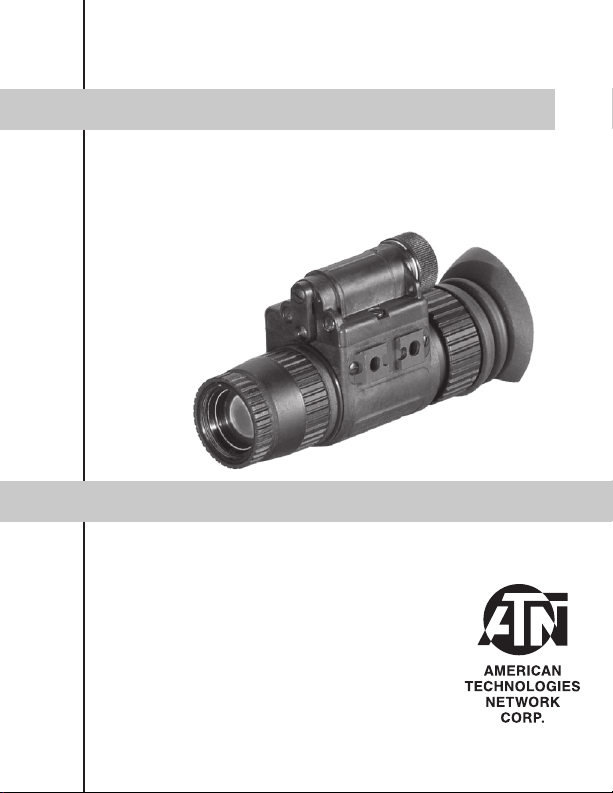
ATN NVM14
Mfg’s P/Ns:
ATN NVM-14-2 (Gen2 +)
ATN NVM-14-2I (Gen2+)
ATN NVM-14-CGT (Gen2+)
ATN NVM-14-HPT (Gen2+)
ATN NVM-14-3 (Gen3)
ATN NVM-14-3A (Gen3)
ATN NVM-14- 4 (Gen4)
o p e r a t o r s ’ s m a n u a l
Imp ortant Export Restricti ons ! Commo dit ies, products, technologies and services contained in this manual
are subject to one or more of the export control laws and
regulations of the U.S. Government and they fall under the
control jurisdic tion of either the US Department of State
or the US BIS-Departme nt of Commerce. It is unlawful
and s tric tly prohibited to export, or att empt t o expo rt or
other wise transfer or sell any hardware or tec hnical data
or furnish any se rvice to any fore ign person, w het her
abroad or in the United States, for which a license or written approval of the U.S. Government is required, without
fir st o btainin g th e requir ed l icense or wr itt en approval
from the De par tment of th e U. S. Gov ern men t h avi ng
jurisdict ion. Diversion contr ary to U.S. law is prohibited.
Page 2

Manual (NVM14- 003) Revision 1 - December 200 6
The information in this manual furnished for information use only, is subject to
change without notice, is not to be construed as a commitment by ATN Corp.
ATN Corp. assumes no responsibilit y or liability for any errors or inaccuracies that may appear in this book.
© 2006 ATN Corp. All right reser ved.
Page 3

SAFETY SUMMARY
CAUTIONS
• The ATN NVM-14 is a precision optical instrument and must be
handled carefully at all times to prevent damage.
• Do not scratch the external lens surfaces or touch them with
your fingers.
• Wiping demisting shield with lens paper while wet or with wet
lens paper can damage the coating.
• To protect the image intensifier, keep the lens cap on the objective lens when the monocular is not in use or when checked out
in daylight conditions.
• The IR illuminator is a light that is invisible to the unaided eye
for use during conditions of extreme darkness. However, the
light from the illuminator can be detected by the enemy when
using night vision devices.
• If you use the rubber eyecaps for a long period of time, you may
suffer skin inflammation. If you develop any symptoms, consult
a doctor immediately.
a
Page 4

NOTES
• When utilizing the ATN NVM-14 for driving purposes, the goggles may not be used in the hand-held mode. The goggles must
be worn in the head- or helmet-mounted position.
• At operating temperatures below –20°C (-4°F), alkaline batteries are not recommended, as operating life will be severely
reduced. Lithium-iron disulfide 1.5V AA batteries or equivalent
should be used below –20°C (-4°F).
• The purpose of the illuminator is for viewing at close distance
up to 3 meters when additional illumination is needed.
b
Page 5

EQUIPMENT LIMITATIONS
To avoid physical and equipment damag e when using t he ATN
NVM-14, carefully read and understand the following safety precautions.
• The equipment requires some night light (moonlight, starlight,
etc.) to operate. The level of performance depends upon the level
of light.
• Ni ght light is reduce d by passing cloud c over, while operating
under trees, in building shadows, etc.
• The equipment is less effective viewing into shadows and other
darkened areas.
• The equipment is less effective through rain, fog, sleet, snow or
smoke.
• The equipment will not “see” through dense smoke.
• Adjust vehicular speed to prevent overdriving the range of view
when conditions of possible reduction or loss of vision exist.
c
Page 6

TABLE OF CONTENTS
Section Title Page
Safety Summary a
Table Of Contents i
List of Figures ii
List of Tables iii
How To Use This Manual iv
Section I General Information 1-1
II Equipment Description 2-1
III Mounting Procedures 3-1
IV Operating Procedures 4-1
V Operational Defects 5-1
VI Maintenance 6-1
Appendix A End Item Components A-1
Appendix B Repair Parts List B-1
Index IND-1
For Technical Information INFO-1
i
Page 7

LIST OF FIGURES
Figure Title Page
1-1 Helmet Mounted Multi-Use Minimonocular 1-2
2-1 ATN NVM-14DNS Major Components 2-4
2-2 ATN NVM-14 Optional Components 2-4
3-1 Attaching ATN NVM-14 to Head Mount 3-2
3-2 Attaching ATN NVM-14 to Helmet Mount 3-3
3-3 Attaching ATN NVM-14 to Weapon Mount 3-4
3-4 Mounting the ATN NVM-14 to a scope 3-5
3-5 Adapter for using ATN 3.5x 26 scope 3-6
3-6
Mounting the Picatinny Adapter to the ATN NVM-14
3-7 Attaching ATN NVM-14 to PVS-7 Adapter 3-7
3-8 Attaching ATN NVM-14 to PVS-7 Headmount 3-8
3-9 Mounting 3x and 5x Lens to the ATN NVM-14 3-8
4-1 CR123A Battery Installation 4-3
4-2 AA Batter y Installation 4-4
4-3 Mechanical Functions 4-5
4-4 Infrared (IR ) Illuminator Operations 4-6
5-1 Shading 5-2
5-2 Edge Glow 5-3
5-3 Bright Spots and Emission Points 5-5
5-4 Fixed Pattern Noise 5-6
5-5 Chicken Wire 5-7
3-6
6-1 Neckpad Reinstallation 6-11
6-2 Lacing the Sliding Bar Buckle 6-12
6-3 Assembling of the tube into the NVM-14 6-13
ii
Page 8

LIST OF TABLES
Table Title Page
2-1 ATN NVM-14DNS Major Components 2-5
4-1 Batter y Life 4-2
6-1 Preve nt ive M ai nten an ce Ch ec ks an d
Service for the ATN NVM-14
6-2 Operator Troub lesho oting for the ATN
NVM-14
A-1 ATN NVM-14 End Item Components A-1
B-1 ATN NVM-14 Repair Parts List B-1
iii
6-2
6-8
Page 9

HOW TO USE THIS MANUAL
USAGE
You m ust familiar ize yourself with the entire manual b efore
operating the equipment. Read the complete maintenance task
before performi ng maintenance and follow all WARNINGS,
CAUTIONS, and NOTES.
MANUAL OVERVIEW
The manual contains sections for Operating and Maintaining
the Day Night SightMulti-Use Minimonocular NVG.
Components of End Item are in Appendix A.
Repair Parts List is in Appendix B.
iv
Page 10

v
Page 11

SECTION I
GENERAL INFORMATION
1
Page 12
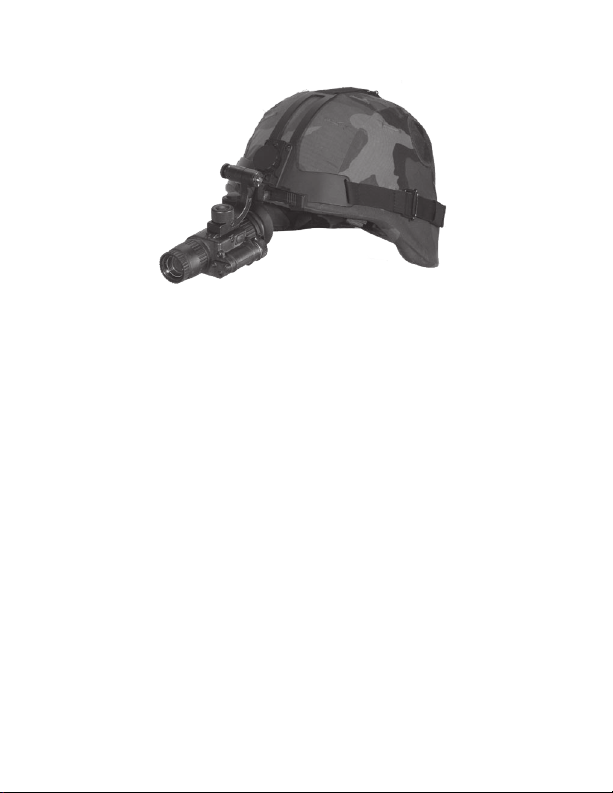
Helmet Mounted Multi- Use Minimonocular
2
Figure 1-1
Page 13

1-1 GENERAL INFORMATION
A. TYPE OF MANUAL
Operator (Including Repair Parts List).
B. MODEL NUMBER AND EQUIPMENT NAME
ATN NVM-14 – Multi-Use Minimonocular
C. SUPPLIER
American Technologies Network Corp.
20 South Linden Ave. Unit 1B,
South San Francisco, CA 940801
D. PURPOSE OF EQUIPMENT
To provid e the soldier with the abilit y to obser ve at night
under moonlight and starlight conditions. The ATN NVM-14
can be handheld, head mounted, helmet mounted or weapon
mounted to enable walking, driving, weapon firing, shortrange surveillance, map reading, vehicle maintenance, and
administering first aid. The unit allows for horizontal and vertical adjustments when head or helmet mounted and is also
equipped with an infrared light-emitting source.
3
Page 14

1-2 WARRANTY INFORMATION
This item shall conform to design, manufact uring, and performance requirements and be free from defec ts in material
and workmanship for a period of two (2) years from the date of
acceptance. If item is defective, notify your Service Command
Technical point of contact.
1-3 TECHNICAL INFORMATION
Fo r tec hnica l inf ormat io n contac t ATN Cor p. d ir ec tly at
(650) 875-0130, or info@atncorp.com your Service Command
point of contact.
1-4 LIST OF ABBREVIATIONS
BAT - Battery
Illum - Illuminator
IR - Infrared
mm - Millimeters
NVG’s - Night Vision Goggles
4
Page 15

SECTION II
EQUIPMENT DESCRIPTION
1
Page 16

2.1 SYSTEM DESCRIPTION
The ATN NVM-14 is a hand-hel d, h ead- mounted , he lmetmounted, or weapon-mounted night vision system that enables
walking, driving, weapon firing, short-range surveillance, map
reading, vehicle maintenance, and administering first aid in both
moonlight and starlight. Each unit allows for vertical adjustment
(by using head straps), fore-and-aft adjustment, objective lens
focus, and eyepiece focus. The device is also equipped with an
infrared light-emitting source.
NVM-14 Night Vision monocular utilizes the principle of intensification of the residual light which is reflected from the surrounding objects. The optical system of the monocular consists of: an
objective lens, an image intensifier tube and an eyepiece.
Even under unsteady brightness conditions, Automatic Brightness Adjustment System always keeps the IIT brightness level
constant.
The Automatic Protective System controls the existing illumination level through the photo receiver. If the illumination level surpasses 100-300 lx for the following 10 seconds, the monocular
will shut off automatically
Built-in IR Illuminator makes it possible to observe the objects
when the monocular works in the conditions of low light or total
darkness.
The eyepiece incorporates several LED indicators:
- RED – serves as an IR Illuminator Indicator and an Battery Low
Indicator at a time. IR is on when the indicator light becomes
stable. If the indicator light starts flickering, it means there might
be about 20% of battery charge left.
- GREEN – serves as an Excessive Brightness Indicator. If the
bright light remains unchanged for over 10 seconds after the
indicator turns on, the monocular will automatically shut-off. If
you move the unit away from the bright/excessive light the unit
will turn back on again.
2
Page 17

2.2 WEIGHT, DIMENSIONS, AND
PERFORMANCE
WEIGHT AND DIMENSION
Weight (with battery) 335 grams
Length 140 mm
Width 50 mm
Height 69 mm
PERFOMANCE
Magnification 1X
f-Number 1.2
Field of View 40 degrees
Eyepiece Diopter Adj. -6 to +2
Eye Relief 25 mm
Focusing range
Voltage 3.0 VDC or 1.5 VDC
Power Requirements 1 CR123A or 1 AA
IR Illumination Range 20 meters
CONTINUOUS OPERATION
1 CR123A battery 40 hours
0,25m to innity
3
Page 18
2.3 DESCRIPTION OF MAJOR
COMPONENTS
4
6
2
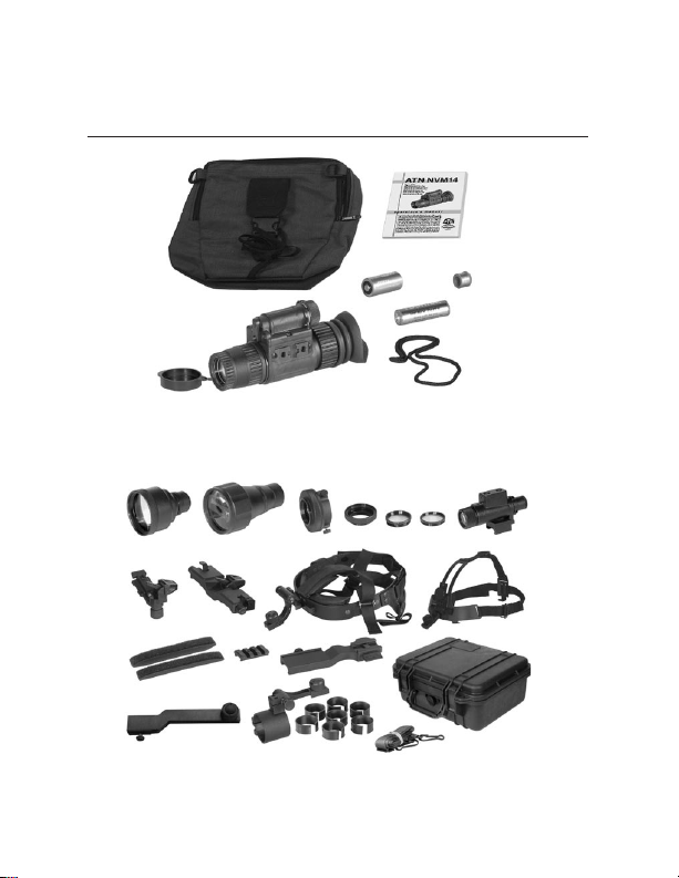
ATN NVM-14 Major Components
1 2
8
12
15
4
9
13
16
ATN NVM-14 Optional Components
1
Figure 2-1
3
10
14
Figure 2-2
3
4
5
17
5
8
7
9
7
6
11
18
Page 19

TABLE 2-1 ATN NVM-14DNS MAJOR COMPONENTS
ITEM DESCRIPTIONKit Components
Kit Components
1 Multi-Use Minimonocular
2 Lens Cap
3 Eye-cup
4 Soft Carrying Case
5 Operators Manual
6 Battery 123A Lithium
7 Battery AA Alkaline
8 Battery Adapter
9 Neck Cord
Optional Components
1 3X Afocal Lens
2 5X Afocal Lens
3 Camera/Camcorder Adapter
4 Lens adapter for ITT 3X and 5X Lenses
5 Demist Shield
6 Sacrificial Window
7 IR- 450 IR illuminator
8 Headmount Adapter for PVS7 Headmount Assembly
9 Dual Bridge Adapter for PVS7 Headmount Assembly
10 Headmount Assembly
11
12 Brow Pads
13 Picatinny Adapter
14 Weapon Mount Piccatiny /Mil 1913
15
16 Scope Adapter Mount with inserts
17 Shoulder Strap
18 Hard Shipping/Storage Case
Flip-up Helmet Mount
Adapter for using MUM with the ATN 3.5x26 riflescope
5
Page 20

KIT COMPONENTS
1) Multi-Use Minimonocular
The monocular night vision device with unity magnifi
cation.
2) Lens Cap
A cap used to protect the lens and for testing the unit
in daylight.
3) Eye-cup
A rubber cup used to protect eyepiece and for opera
tor comfort.
4) Soft Carrying Case
A protective bag used for storing of ATN NVM-14 and
accessories.
5) Operators Manual
Provides equipment description, use of operator con
trols and preventative maintenance checks and service.
6) Battery 123A Lithium
A single, 123A lithium battery used to power the unit.
7) Battery AA Alkaline
A single, standard AA alkaline battery used to power
the unit.
8) Battery Adapter
Allows the ATN NVM-14 to accept a single, standard
AA alkaline battery used to power the unit.
-
-
-
6
Page 21

OPTIONAL COMPONENTS
1) 3X Afocal Lens
Attaches to the ATN NVM-14 for enhanced range per
formance; but, reduces the field of view to 13 deg.
2) 5X Afocal Lens
Attaches to the ATN NVM-14 for enhanced range per
formance; but, reduces the field of view to 8 deg.
3) Camera /Camcorder Adapter
This adapter attaches to the ATN NVM-14 eyepiece
for collection of imagery from the ATN NVM-14.
4) Lens Adapter (option for ITT only)
This item for mount 3X or 5X Afocal lens (ITT part
#A325639/2750SJ) to the ATN NVM-14.
5) Demist Shield
Used to prevent eyepi ece lenses from becoming
fogged.
6) Sacrificial Window
A replaceable window supplied to protect the objec
tive lens during operation in adverse conditions.
7)
IR-450 IR illuminator
450 mW infra-red illuminator is powerfull for long
range night vision in the total darkness.
8)
Headmount Adapter for PVS7 Headmount Assembly
This item allows the attachment of the ATN NVM-14 to
the PVS7-headmount or PVS7-helmet mount.
9)
Dual Bridge Adapter for PVS7 Headmount Assembly
Adapter that allows the ATN NVM-14 to be attached to
in a binocular configuration to the PVS7-headmount
or PVS7-helmet mount.
-
-
-
7
Page 22

10) Headmount Assembly
Adjustable universal assembly that secures the ATN
NVM-14 to the operator’s head providing hands free
operation.
11) Flip-up Helmet Mount
Provides mount inter face for the ATN NVM-14 to a
range of ballistic helmets.
12) Brow Pads
Changeable pads for secure head mount fit.
13) Picatinny Adapter
2” Picatinny rail for additional lighting, laser and other
mission critical tools.
14) Weapon Mount
Small arms adapter that allows the ATN NVM-14 to be
mounted on a weapon using Piccatinny or Mil 1913
rail.
15)
Ad apter f or u si ng M UM wit h the ATN 3.5x 26
riflescope
Ada p ter fo r us ing the ATN NVM -14 with the
ATN 3.5x26 riflescope.
16) Scope Adapter Mount with inserts
Day/ Night System Flip-up Adapter with Inserts with
inserts for variety of scopes/telescopes.
17)
Shoulder Strap
18) Hard Shipping/ Storage Case
A protective case used for shipping/storing of ATN
NVM-14 and accessories.
8
Page 23

SECTION III
MOUNTING PROCEDURES
1
Page 24

3.1 MOUNTING PROCEDURES
A. MOUNTING THE ATN NVM-14 TO A HEADMOUNT
To mount the ATN NVM-14 to a headmount, perform the following:
1. Lo osen the s crew (A). Push the button ( B) and in ser t t he
bracket of the NVM-14 into the rail (C) of the headset.
2. Place the headmount with NVM-14 onto a head.
3. Loosen the screw (A) and move the unit along the rail for eye
relief adjustment.
4. The NVM-14 headmount has a flip-up mechanism. Push the
button (D) on the side of mount and lift the unit up until the unit
fixates in the top position. The device in top position will turned
off automatically.
5. Push the same button to lower NVG-7 to viewing position.
Turn the device on for continuation of the operation.
6. The NVM -14 can be placed onto the right or left eye. In order to reajust the monocular for another eye, take the unit off
the headmount adapter, turn the unit other side (for 180º) and
mount it on the headmount adapter through the Picatinny rail
on this side. Push the button (E) and move the device along
the slide-rail (F) for comfortable position.
D
B
A
C
F
E
Attaching ATN NVM-14 to Head Mount
2
Figure 3-1
Page 25

B. MOUNTING THE ATN NVM-14 TO A HELMET
Helmet mount for attachment of ATN NVM-14 to a standard PASGT helmet. Helmet mount fits securely onto helmet via a rugged
strapping device and grooved hooks. With helmet mount, NVM14 can be positioned directly in front of user’s eyes or flipped.
1. Install the mount onto helmet as shown on the picture.
2. Tighten and fixate the straps (A)
3. Attach goggles to the rail.
4. Loosen t he screw (C). Push the button ( B) and ins ert the
bracket of the NVM-14 into the rail (D) of the helmetset.
5. Place the helmet with NVM-14 onto a head.
6. Loosen the screw (C) and move the unit along the rail for eye
relief adjustment.
7. The NVM-14 helmetmount has a flip-up mechanism. Push the
button (E) on the side of mount and lift the unit up until the unit
fixates in the top position. The device in top position will turned
off automatically.
8. Push the same button to lower NVG-7 to viewing position.
Turn the device on for continuation of the operation.
9. The NVM-14 can be placed onto the right or left eye. In order
to reajust the monocular for another eye, take the unit off the
headmount adapter, turn the unit other side (for 180º) and
mount it on the headmount adapter through the Picatinny rail
on this side. Push the button (E) and move the device along
the slide-rail (F) for comfortable position.
A
E
B
C
D
F
Figure 3-2
Attaching ATN NVM-14 to Hlmet Mount
A
3
Page 26

CAUTION
It is recommended that the eyecup be replaced with the eyeguard during weapon-mounted use.
NOTE
The ATN NVM -14 is not a weapo n s ight, however, it can be
used in conjunction with a collimated dot sight or laser aiming
device.
C. MOUNTING THE ATN NVM-14 TO THE WEAPON
To mount the ATN NVM-14 perform the following:
1. Loosen the clamping knob on the weapon mount. Position the
monocular mount on the weapon’s mounting rail, adjust the
fore/aft position of the monocular as necessary by loosening
the clamping knob and repositioning the weapon mount on the
rail. Tighten by turning the clamping knob).
2. Align the monocular and the weapon mount. Slide the monocular rearwards until the alignment boss aligns with the alignment groove on the weapon mount. Push until the monocular
locks into the weapon mount (see figure 3-1).
Attaching ATN NVM-14 to Weapon Mount
4
Figure 3-3
Page 27

D. MOUNTING THE ATN NVM-14 TO A SCOPE
Day/Night System may be mounted with Flip-up Scope Adapter
Mount for NVM-14 and variety of daytime scopes/telescopes.
1. Loosen the adapter fixing screws (A).
2. Put the insert into the adapter (ATN supplies inserts of different sizes for their coupling with 38 mm to 43 mm eyepieces).
3. Now at tach the monocular to the bracket (B). You can push
the monocular rail into the bracket guide (C) and then take it off
the bracket only when you loosen the fixation knob (D) holding
the button (2) pressed at a time. With the fixation knob (D) tightened you secure the monocular on the bracket.
4. Push a daytime riflescope eyepiece into the adapter attached
to the monocular, making sure a small space is left between the
riflescope eyepiece and the monocular front lens.
5. Tighten the adapter screw(A) securely.
6. By press ing button (F) on the adap ter yo u can ra ise the
monocular 180 degrees upward in order to work with the daytime scope only.
C
BA
D
E
F
Mounting the ATN NVM-14 to a scope
Figure 3- 4
5
Page 28

E. MOUNTING ATN NVM -14 ON TO ATN 3.5X26
SCOPE
There are special adapter for using the ATN NVM-14 with the
ATN 3.5x26 riflescope.
To mount the ATN NVM-14 perform the following:
1. Loosen the the mounting screw (A) of adapter.
2. M ount the adapter onto the back Pi catinny rail of the ATN
3.5x26 riflescope.
3. Tighten the mounting screw of adapter.
4. Loosen the screw ( B) of ad apter. Push the button (C) and
insert the bracket of the NVM-14 into the rail of the adapter.
5. Loosen t he screw (B) and move the unit along the rail for
adjustment.
C
B
A
Adapter for using ATN 3.5x26 scope
Figure 3- 5
F. MOUNTING THE PICATINNY ADAPTER TO THE
ATN NVM-14
Mount Picatinny adapter(A) onto one of the rails on the monocular. Tighten two fixing screws of the adapter.
A
B
Mounting the Picatinny Adapter to the ATN NVM-14
6
Figure 3- 6
Page 29

G. MOUNTING CAMERA /CAMCORDER TO THE
ATN NVM-14
1. Screw Camera Adapter into the front lens of a photographic
camera (thread M52x0.75) or a video camera (use adaptor ring
threaded M37x0.75).
2. Remove the rubber eyecup off the monocular.
3. Connect the adapter with the eyepiece and tighten 3 fixing
screws on the adapter.
H. MOUNTING IR-450 TO THE ATN NVM-14
IR-450 may be mounted on the monocular through the Picatinny
adapter.
1. Install the Picatinny Adapter on one of the monocular rails
(See cl. 3.4.F).
2. Loosen the IR-450 fixing screw.
3. Mount the IR- 450 on the Picatinny Adapter and tighten the
fixing screw.
I. MOUNTING THE ATN NVM-14 TO THE PVS -7
HEAD/ HELMET MOUNT
To mount the ATN NVM-14 to a head/helmet mount, perform the
following:
1. Attac h the PVS- 7 head mount adapter (A) to the rail ( B) of
ATN NVM-14.
E
A
B
D
C
Figure 3-7
Attaching ATN NVM-14 to PVS-7 Adapter
7
Page 30

With this adapter you may see through the eyepiece using either
right or left eye. To change the viewing eye, loosen the nut(C)
and turn the adapter(D) in the point of connection to match with
another eye. Tighten the nut(C) anew. To disconnect the adapter press the upper clip(E).
2. Align the headmount adapter and the head /helmet mount.
Slide the monocular rearwards until the alignment boss aligns
with the alignment groove on the head/helmet mount. Push
until the monocular locks into the head/helmet mount.
Attaching ATN NVM-14 to PVS-7 Headmount
Figure 3- 8
J. MOUNTING 3X OR 5X LENS TO THE ATN NVM-14
Screw the 3x or 5x Lens into the threading of the front
lens of the monocular.
Mounting 3x and 5x Lens to the ATN NVM-14
Figure 3-9
K. MOUNTING 3X OR 5X LENS (ITT) TO THE ATN NVM-14
Screw Lens Adapter into the front lens of the monocular.
Then screw the 3x or 5x IIT Afocal Lens into the threading
of the Lens Adapter.
8
Page 31

SECTION IV
OPERATING PROCEDURES
1
Page 32

4.1 OPERATING INSTRUCTIONS
A. BATTERY INSTALLATION
CAUTION
To protect the imag e intensifier, keep the lens cap on the
objective lens when the monocular is not in use or when
checked out in daylight conditions.
NOTE
At operating temperatures below –20°C (-4°F), alkaline batteries are not recommended, as operating life will be severely
reduced. Lithium-iron disulfide 1.5V A A batteries or equivalent
should be used below –20°C (-4°F).
Table 4-1 Battery Life
Estimated Battery Life
Bettery Type Usage
CR123A >40 Hours
Standard AA >20 Hours
The ATN NVM-14 operates with one CR123A battery or one AA
battery when using the AA battery adapter.
2
Page 33

Install CR123A batteries as follows:
1. Unscrew the battery cap (A) and insert the battery (B), observing the polarity as indicated.
2. Replace the battery cap (A) and screw cap hand tight.
A
B
Figure 4-1
CR123A Battery Installation
3
Page 34

Install standard AA batteries as follows:
1. Unscrew the batter y cap (A).
2. Unscrew the CR123 battery adapter(B) from the cap.
3. Insert AA batter y and, observing the polarity as indicated.
4. Replace the battery cap and screw cap hand tight.
B
A
Figure 4-2
AA Battery Installation
4
Page 35

B. MECHANICAL FUNCTIONS
The mechanical fu nctions of the ATN NVM -14 allow for differences in the physical features of individual operators and
provide for operating the system. These functions include the
On /Off/ On IR control, eye relief (see Section III Mounting
Procedures – Headmount Adjustments), diopter adjustment,
objective l ens focus, and IR illumin ator focusing. These
mechanical controls are identified in Figure 4-3.
Operation button (A) switches both the monocular and the IR
Illuminator on/off.
To turn the monocular on, press button (A) by one short push, to
turn it off – press button (A) by another short push.
You may adjust the unit diopter by rotating the eyepiece ring (B).
The total dioptric range is covered in 1/2 revolution.
To make the unit focus appropriate for different distances you
should rotate the front lens ring (C). The total focusing range is
covered in 1/3 ring revolution.
C
B
A
Figure 4- 3
Mechanical Functions
5
Page 36

C. INFRARED (IR) ILLUMINATOR OPERATIONS
CAUTION
The IR illuminator is a light that is invisible to the unaided
eye for use during conditions of extreme darkness. However, the light from the illuminator can be detected by the
enemy using night vision devices.
NOTE
The purpose of the illuminator is for viewing at close distance up
to 3 meters when additional illumination is needed.
IR Illuminator gets activated when the monocular is a lready
on by holding button (A) pressed for 1,5-2 seconds. A red light
appears in the eyepiece to indicate that the IR illuminator is
operating.
You may focu s IR li ght by placin g the focusing l ens of pivot
plate(B) onto the window of IR illuminator ( C).
C
A
B
Infrared (IR) Illuminator Operations
Figure 4- 4
6
Page 37

SECTION V
ZEROING OPERATIONAL
DEFECTS
7
Page 38

5-1 ZEROING OPERATIONAL DEFECTS
Operational defects relate to the reliability of the image intensifier and are an indication of instability. If identified, they are an
immediate cause for rejecting the ATN NVM-14. They include
shading, edge glow, flashing, flickering, and intermittent operation.
A. SHADING
If shading is persistent, you will not see a fully circular image
(Figure 5-1). Shading is very dark and you cannot see an image
through it. Shad ing always begins on the ed ge and migrates
inward eventually across the entire image area. Shading is a
high contrast area with a distinct line of demarcation. Return the
ATN NVM-14 to the maintainer.
Figure 5-1
Shading
NOTE
Make sure the shading is not the result of improper eye-relief
adjustment.
8
Page 39

B. EDGE GLOW
Edge glow is a bright area (sometimes sparkling) in the outer
portion of the viewing area (see Figure 5-2). To check for edge
glow, block out all light by cupping a hand over the lens. If the
image tube is displaying edge glow the bright area will still show
up. Return the ATN NVM-14 to the maintainer.
Mode Selector SwitchEdge Glow
Figure 5-2
9
Page 40

C. FLASHING, FLICKERING, OR INTERMIT TENT
OPERATION
The image may appear to flicker or flash. If there is more than
one fli cker, check for loose battery adapter or weak bat ter y.
Return the ATN NVM-14 to the maintainer.
D. COSMETIC BLEMISHES
These are usually the result of manufacturing imperfections that
do not affect image intensifier reliabilit y and are not normally
a cause for rejecting ATN NVM-14. However, some t ypes of
blemishes can get worse over time and interfere with the ability
to perform the mission. If you believe a blemish is a cause for
rejection, record the specific nature of the problem on the maintenance forms and identify the position of the blemish by using
the clock method and approximate distance from the center (e.g.,
5:00 toward the outside, 2:30 near the center, or 1:00 midway).
The following are cosmetic blemishes:
1. Bright Spots.
A bright spot is a small, non-uniform, bright area that may flicker
or appear constant (Figure 5-3).
Not all bright spots make the ATN NVM-14 rejectable. Cup
your hand over the lens to block out all light. If the bright spot
remains, return the ATN NVM-14 to the maintainer. Bright spots
usually go away when the light is blocked out. Make sure any
bright spot is not simply a bright area in the scene you are viewing. Bright spots are acceptable if they do not interfere with
the ability to view the outside scene and the ability to perform the mission.
10
Page 41

2. Emission Points.
A steady or fluctuating pinpoint of bright light in the image area
and does not go away when all light is blocked from the objective
lens of the monocular (Figure 5-3). The position of an emission
point within the image area does not move. Not all emission
points make the ATN NVM-14 rejectable. Make sure any emission point is not simply a point light source in the scene you are
viewing. Emission points are acceptable if they do not interfere
with the ability to perform the mission.
Bright Spots and Emission Points
Figure 5- 3
3. Black Spots.
These are cosmetic blemishes in the image intensifier or dirt or
debris between the lenses. Black spots are acceptable as long
as they do not inter fere with viewing the image. No action is
required if this condition is present unless the spots interfere with the operator’s ability to perform the mission.
1
Page 42

4. Fixed-Pattern Noise.
This is usually a cosmetic blemish characterized by a faint hexagonal (honeycomb) pattern throughout the viewing area that
most often occurs at high light levels or when viewing very bright
lights (See Figure 5-4). This pattern can be seen in every image
intensifier if the light level is high enough. This condition is
acceptable as long as the pattern does not interfere with
viewing the image and interfere with the ability to perform
the mission.
Figure 5- 4
Fixed Pattern Noise
2
Page 43

5. Chicken Wire.
An irregular pattern of dark thin lines in the field of view either
throughout the image area or in parts of the image area (See
Figure 5-5) . Under the wor st-case condition, these lines will
form hexagonal or square-wave shaped lines. No action is
required if this condition is present unless it interferes with
the viewing the image and interfere s with the op erator’s
ability to perform the mission.
Figure 5- 5
Chicken Wire
3
Page 44

4
Page 45

SECTION VI
MAINTENANCE
1
Page 46

Not Fully Mission
Capable If
Not Current.
6-1 PREVENTIVE MAINTENANCE
Fault not corrected.
Procedure
• Open carrying case, inventory items
and check records for 180-day services
completed.
• Previously recorded faults on mainte-
Location Item to
Check /Service
Inter val
TABLE 6.1 PREVENTIVE MAINTENANCE CHECKS AND SERVICES FOR ATN NVM-14
Item
No.
1. Before Maintenance
Scratches or chips
hinder vision with
monocular turned on,
or if cracks are present.
Cracked or damaged.
MONOCULAR
nance records.
Inspect lens for dirt, fingerprint residue,
chips, or cracks. If necessary, clean
and dry lens with water and lens tissue.
Inspect for cracks or damage.
Scratches and gouges are OK if opera-
tion is not affected
Optic al
Surfaces
External
Surfaces
2. Before /After
3. Before /After
2
Page 47

(CONT.)
Not Fully Mission
Capable If
Adapter is missing,
contacts damaged or
corroded, or o-ring is
missing.
Binding, not moving
freely or too loose.
Procedure
Check to make sure batter y adapter
is present. Remove battery adapter
and inspect for corrosion, moisture,
corroded or defective contacts, and that
o-ring is present.
Rotate diopter adjustment ring to make
sure the eyepiece is not too tight or too
loose. Range is approximately ½ turn.
Inspect for dirt, dust, and cracked or torn
cup. Inspect for bent, broken or improp-
Location Item to
Check /Service
Battery Adapter /
Compartment
Diopter Adjust-
ment Ring
Inter val
Binding or not moving
freely.
erly fitting eye cup. If necessar y, clean
with water.
Rotate objective lens focus knob
to ensure free movement (range is
approx. 1/3 turn
Objec tive Lens
Focus Knob
Switch has no definite
stopping points or knob
is broken or missing.
Inspect for cracked, torn, or missing
lens cap.
Turn switch OFF to ON. Each position
should have a definite stopping point.
Inspect for broken or missing knob.
TABLE 6.1 PREVENTIVE MAINTENANCE CHECKS AND SERVICES FOR ATN NVM-14
Item
No.
4. Before/After
5. Before/After
6. Before/After Eyecup
7. Before/After
8. Before/After Lens Cap
9. Before/After On/Off Switch
3
Page 48

(CONT.)
Not Fully Mission
Capable If
Flickering, flashing,
edge glow, or shading
is observed.
Damage causes straps
or pads to be unserv-
iceable.
Damaged, latch won’t
work or too loose.
Binding, damaged or
non-operational slide
mechanism.
Binding, damaged or
non-operational slide
mechanism.
Refer to Section V – Operation Defects
– to inspect for operational defects.
Inspect for cuts, tears, fraying, holes,
cracks, or defective fasteners.
Inspect for dirt, dust, or corrosion.
Inser t ATN NVM-14 latch into socket to
verify secure attachment of ATN NVM-
14 to headmount. If necessary, clean
socket with water.
Press the socket-release button and
check for free motion. Inspect for
damage.
Press the socket-release button and
check for free motion. Inspect for
Procedure
Location Item to
Check /Service
Inter val
TABLE 6.1 PREVENTIVE MAINTENANCE CHECKS AND SERVICES FOR ATN NVM-14
Item
No.
10. Before/After Viewed Image
11. Before/Af ter Strap Pads
12. Before/After Socket
For and Aft
Adjustments
13.
damage.
For and Aft
Adjustments
13.
4
Page 49

(CONT.)
Not Fully Mission
Capable If
Damaged, will not latch
securely.
Damaged, will not
mount to ATN NVM-14
or will not mount to
weapon mount rail.
Procedure
Inspect for dirt, dust, or corrosion.
Inser t into headmount or helmet mount
socket to verify secure attachment.
IInspect for dust, dirt, or corrosion.
Location Item to
Check /Service
Headmount /
Helmet Mount
Adapter
Small Arms
Mount Adapter
Inter val
TABLE 6.1 PREVENTIVE MAINTENANCE CHECKS AND SERVICES FOR ATN NVM-14
Item
No.
15. Before/After
16. Before/After
CAUTION
The demist coating on the demist shield can be damaged if cleaned while wet or cleaned with
wet lens paper. Clean only when the demist shield is dry and only use dry lens paper.
5
Page 50

(CONT.)
Not Fully Mission
Capable If
Damage or scratches
hinder vision with ATN
NVM-14 on.
Damage or scratches
hinder vision with ATN
NVM-14 on.
Damage or scratches
hinder vision.
Procedure
Inspect for dirt, dust, scratches or
damage. If necessary, clean when
shield is dry with dry lens tissue only.
Inspect for dirt, dust, scratches, or
damage. If necessary, clean.
Inspect optical surface for dirt, dust,
scratc hes or cracks.
Remove all items and shake out loose
dirt or foreign material. Inspect for
tears, cuts, excess wear or damage to
mounting clips.
Inspect for cuts, tears, or excess wear
or damaged clips.
Location Item to
Check /Service
Inter val
Sacrificial
Window
TABLE 6.1 PREVENTIVE MAINTENANCE CHECKS AND SERVICES FOR ATN NVM-14
Item
No.
17. Before /After Demist Shield
18. Before /After
19. Before /After 3X Magnifier
20. Before /After Carrying Case
21. Before /After Shoulder Strap
6
Page 51

6-2 OPERATOR TROUBLESHOOTING
Table 6-2 lists common malfunctions that you may find with
your equipment. Perform the tests, inspections, and corrective
actions in the order they appear in the table.
This table cannot list all the malfunctions that may occur, all the
tests and inspections needed to find the fault, or all the corrective actions needed to correct the fault. If the equipment malfunction is not listed or actions listed do not correct the fault,
notify your maintainer.
7
Page 52

Turn switch to OFF position and then
ON.
Replace batteries or install correctly.
If IR illuminator fails to activate, refer to
higher level of maintenance.
Visual.
Check for defec tive, missing or improp-
erly installed batteries.
In a dark location with system turned on,
activate IR. Visually check IR illuminator
operation; scene should brighten.
TABLE 6. 2 OPERATOR TROU BLESHOOTING FOR ATN NVM-14
Malfunction Test or inspection Corrective Action
1. Monocular fails to
activate.
2. IR illuminator fails
to activate.
•Refocus.
•Clean lens surface.
• If image quality is still poor, refer to
higher level of maintenance.
• Readjust for proper eye-relief distance.
• If eyecup is defective, refer to higher
level of maintenance.
Visual. Refer to higher level of maintenance.
• Check objective lens or ey piece focus.
• Check for fogging or dirt on lens.
• Check eye-relief distance.
• Check eyecup for resiliency.
3. IR indicator fails
to activate.
4. Poor image
quality
5. Light visible
around eyecup
8
Page 53

If damaged, refer to higher level of
maintenance.
• If o-ring is missing, replace.
• If damaged, refer to higher level of
maintenance.
is bent or broken
• Visually inspect for the presence of an
o-ring
Check to see if the diopter adjustment ring
TABLE 6. 2 OPERATOR TROU BLESHOOTING FOR ATN NVM-14 (CONT.)
Malfunction Test or inspection Corrective Action
6. Diopter adjust-
ment cannot be
made
• Check for damaged battery adapter.
7. Battery adapter
difficult to remove.
• Clean socket and latch.
If damaged, refer to higher level of
maintenance.
• If damaged, return both headmount or
head /helmet mount adapter to higher
level of maintenance.
Check for defec tive buckles, fasteners or
straps.
• Check socket or latch for dirt.
• Check socket or latch for damage.
8. Head straps
cannot be tightened
9. Headmount
or helmet mount
socket and
head /helmet mount
maintenance.
Inspect mounting hardware for damage. If damaged, refer to higher level of
adapter latch does
not catch.
10. Helmet mount
will not tighten to
helmet.
9
Page 54

6-3 CLEANING THE ATN NVM-14
CAUTION
The ATN NVM-14 is a precision optical instrument and must
be handled carefully at all times to prevent damage.
Do not scratch the external lens surfaces or touch them
with your fingers.
Wiping demisting shield with lens paper while wet or with
wet lens paper can damage the coating.
Clean monocular with water, if necessary, and dry thoroughly.
Clean lenses with lens paper (and water, if necessary, except for
demisting shield).
6-4 HEADMOUNT MAINTENANCE
A. BROWPAD REPLACEMENT
Replace the browpads when cracked, torn, or contaminated.
Per form the following procedure to remove and rep lac e the
browpads.
1. Firmly grasp the headmount and remove the old browpad.
2. Gently press on the new browpad. Lightly smooth out any
wrinkles in the new browpad.
10
Page 55

B. NECKPAD REINSTALLATION
During operation of the monocular, it is possible for the neckpad
to become separated from its position on the headband. Perform the following procedures to reinstall the neckpad.
1. Lift the upper headband strap retention tab (see Figure 6-1),
allowing the neckpad strap to be inserted underneath.
2. Slip the neckpad strap all the way under the upper strap reten-
tion tab and then pull the lower part of the neckpad strap under
the lower strap retention tab.
3. Repeat steps 1 and 2 for the other side of the headband and
neckpad if necessary.
Figure 6-1
Neckpad Reinstallation
11
Page 56

C. LACING THE SLIDING BAR BUCKLE
While donning and adjusting the headmount, it is possible for a
strap to slip out of a slide fastener. Perform the following procedure to replace the strap and sliding bar buckle.
Thread the strap from the inside of the buckle over the moveable
sliding bar (see Figure 6-2). Thread the strap back through the
buckle but this time under the sliding bar and over the serrated
part of the buckle.
12
Lacing the Sliding Bar Buckle
Figure 6-2
Page 57

6-4 TUBE ASSEMBLING
1. Unscrew the eyepiece (E) from the case of device (A).
2. Unscrew the lock ring (D) from the case of device.
3. To extract the light guide (C) from the case of device.
4. Introduce the tube (B) into the case of device (A).
5. Set the light guide (C) onto the place in the case.
6. Screw the lock ring (D) into the case of device.
7. Screw the eyepiece (E) into the case of device (A).
D
A
C
B
E
Assembling of the tube into the NVM-14
Figure 6-3
13
Page 58

APPENDIX A
END ITEM COMPONENTS
TABLE A-1 ATN NVM-14 END ITEM COMPONENNENTS
ITEM DESCRIPTION
Mini Monocular Assembly
1.
(without Image Intensifier Tube)
2. Swing Arm Interface, Head/Helmet
3. Weapon Mount
4. Operator Manual
5. Demist Shield, Eyepiece
6. Soft Carrying Case
7. Sacrificial Window
8. Should Strap
9. Head Mont Assembly
10. Brow Pad Assembly (Small)
11. Brow Pad Assembly (Medium)
12. Brow Pad Assembly (Large)
14. Lens Cap
16. Eye Cup Assembly
17. CR123A 3.0V DC Batter y, Lithium
18. Battery Adapter for CR123A
19. Battery (AA Alkaline)
1
Page 59

APPENDIX B
REPAIR PARTS LIST
TABLE B-1 ATN NVM-14 REPAIR PARTS LI ST
ITEM DESCRIPTION PART NO.
1.
Battery Cap Insert
2.
Lithium Battery
ALT
AA Alkaline Battery
3.
Purge Screw
4.
Battery Adapter
5.
Lens Cap
6.
Sacrificial Window
7.
Demist Shield
8.
Battery Cap Retainer
9.
Objec tive Lens Assembly
10.
Eyepiece Lens Assembly
11.
Head /Helmet Mount Adapter
12.
Ship /Storage Case
13.
Neck Cord
14.
Soft Carr y Case
15.
Eyecup Assembly
16.
Operator Manual
17.
Shoulder Strap
18.
Headmount Assembly
19.
Dual Bridge Adapter
20.
Scope Adapter Mount
21.
IR450
22.
Picatinny Adapter
23.
Camera Adapter
24.
3X Lens
25.
5X Lens
26.
Lens Adapter
27.
Helmet mount
NVM-138
CR123A
M30-044
7B315
NVM-198
NVM-178
NVM- 032
NVM- 033
NVM-156
NVM- 030
NVM- 035
NVM- 042
7B257-2
7B306
7B262
7B422
NVM- 015
7B267
7B268-A1
1
Page 60

INDEX
A
ABBREVIATIONS, 1-4
B
BATTERY INSTALLATION, 4-2
BATTERY LIFE, 4-2
BLACK SPOTS, 5-5
BRIGHT SPOTS, 5-4
C
CAUTIONS, A, IV
CHICKEN WIRE, 5-7
CLEANING, 6-10
COSMETIC BLEMISHES, 5-4
D
DIOPTER ADJUSTMENT, 4-5, 6-3, 6-9
E
EDGE GLOW, 5-3, 6-4
EMISSION POINTS, 5-5
END ITEM COMPONENTS, A-1
EQUIPMENT LIMITATIONS, C
EYE RELIEF, 2-3, 4-5
EYEPIECE DIOPTER ADJ., 2-3
F
FIXED-PATTERN NOISE, 5-6
FLASHING, FLICKERING, OR INTERMITTENT OPERATION, 5-4
F-NUMBER, 2-3
G
GENERAL INFORMATION, 1-3
H
HEIGHT, 2-3
1
Page 61

I
IR ILLUMINATION RANGE, 2-3
IR ILLUMINATOR, A, 4-6, 6-8
L
LENGTH, 2-3
M
MAGNIFICATION, 2-3
MAINTENANCE, 6-1, 6-8
- HEADMOUNT, 6-10
- PREVENTIVE, 6-2
MECHANICAL FUNCTIONS, 4-5
MOUNTING PROCEDURES, 3-2, 4-5
O
OBJECTIVE LENS FOCUS, 2-2, 4-5, 6-3
ON/ OFF/ON IR CONTROL, 4-5
OPERATING INSTRUCTIONS, 4-2
OPERATIONAL DEFECTS, 5-2, 6-4
OPERATOR TROUBLESHOOTING, 6-7
P
POWER REQUIREMENTS, 2-3
R
REPAIR PARTS, B-1
S
SAFETY SUMMARY, A
SHADING, 5-2, 6-4
SYSTEM DESCRIPTION, 2-2
T
TECHNICAL INFORMATION, 1-4, INFO-1
V
VOLTAGE, 2-3
W
WARRANTY INFORMATION, 1-4
WEIGHT, 2-3
WIDTH, 2-3
2
Page 62

FOR TECHNICAL INFORMATION
ATN CORP.
20 South Linden Ave. Unit 1B,
South San Francisco, CA 940801
(800) 910-2862
(650) 875- 0130 tel.
(650) 875-0129 fax
www.atncorp.com
info@atncorp.com
1
Page 63

2
Page 64

For customer service and
technical support, please contact
American Technologies Network Corp.
North American Office:
20 S. Linden Ave. Suite 1B,
South San Francisco, CA 94080
phone: 800-910-2862, 650-875-0130
fax: 650 -875- 0129
European Office :
phone: 44(0) 870-0111286
fax: 44(0) 845-3349142
The following countries can use our
toll free number 00 800 9102-8620
Austria, France, Germany, Holland, Italy,
Spain, Sweden, Switzerland
www.atncorp.com
©2006 ATN Corporation
 Loading...