

Page 1
user`s guide
Important Export Restrictions! Commodities, products, te chn ol og ie s a nd ser v i c e s contained i n t h i s manual
are subject to one or more of the export control laws and
r eg ul at i o ns o f t h e U. S. G ov e rn me nt a n d t h ey fa l l u nd er t he
control jurisdiction of either the US Department of State
or the US BIS-Department of Commerce. It is unlawful
and strictly prohibited to export, or attempt to export or
otherwise transfer or sell any hardware or technical data
or furnish any service to any foreign person, whether
abroad o r in the Uni te d S t ates, f or w hich a license or writte n approval o f the U.S. Governmen t is re quired, w ith out
first obtaining the required license or written approval
from the Department of the U.S. Government having
jurisdiction. Diversion contrary to U.S. law is prohibited.
AMERICAN
TECHNOLOGIES
NETWORK
CORP.
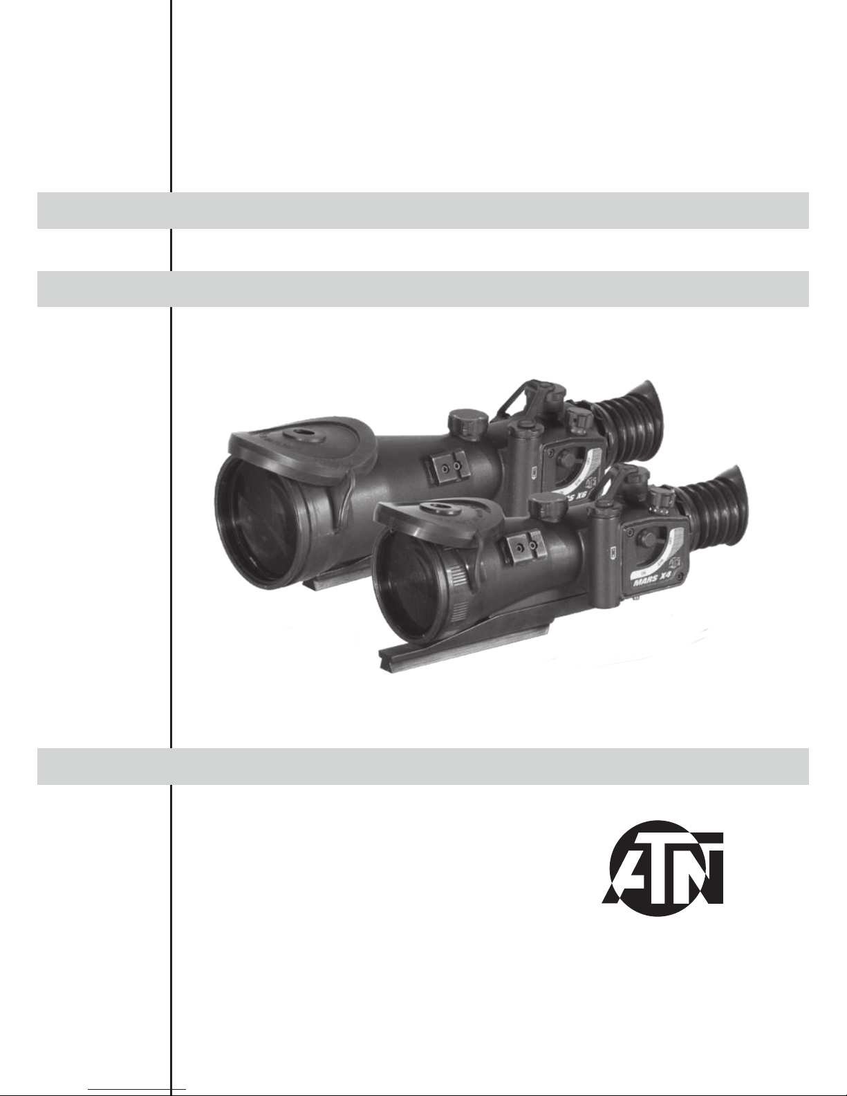
ATN MArs x4
ATN MArs x6
Page 2
The information in this manual furnished for information use only, is subject to change without notice, is not to be
const rue d as a com mit ment by AT N C orp.
ATN Cor p. as sum es no responsib ility or liabil ity fo r any err ors or in acc ura cies t hat may appear in this b ook .
©2008 ATN Corp. All right reserved.
Operation
switch
F1:1. 5 lens
ElevationWindage
-6/+ 2 Di opter
Battery
housing
Mounting
system
IR brightness
adjustment
DIGITAL INFRARED ILLUMINATOR
Battery
housing
Fixation
screw
IR elevation
IR windage
IR focusing
Picatinny rail
Lens cap
• POWERFUL 4X OR 6X M AGNIFICATION
• SUPERIOR QUALITY MULTI-COATED ALL
GLASS OPTICS
• “SINGLE-ELEMENT” ADJUSTABLE FRONT
FOCUS
• NITROGEN-PURGED FOR RESISTANCE
TO INTERNAL FOGGING
• MIL-DOT RETICLE
• CRISP-CLICK PRECISION WINDAGE AND
ELEVATION ADJUSTMENTS
• TARGET TURRETS
• AUTOMATIC BRIGHTNESS CONTROL
• TACTICAL RAIL ENABLING MOUNTING OF
IR ILLUMINATOR OR IR LASER
• LOW BATTERY IN DICATOR
• TACTICAL DIGITAL REMOTE CONTROL
• WATERPROOF AND SUBMERSIBLE TO 66
FEET FOR 1 HOUR
• PELICAN HARD CASE, BATTERIES, USER
GUIDE, NV INSTRUCTIONAL VIDEO AND
ALL NECESSARY MOUNTING HARDWARE ARE INCLUDED
• INCLUDED MOUNT FOR PICCATINY OR
7/8” WEAVER-STYLE RAIL
(M4/M16/AR-15 CARRY HANDLE MOUNT –
OPTIONAL)
• UNIT ACCEPTS EITHER, (1) 3V CR123A OR
(1) AA BATTERY
• DAY TIME COVER WITH IR FILTER
• TWO YEAR WARRANT Y
FEATURES
Remote
control
MARS X4
MARS X6
Focus adjustment
knob
Reticle brightness
adjustment knob
Sensor of system
of automatic bright-
ness control
Th is pro ducT con Tain s n aTur al r ubber laTe x wh ich may cause all ergic reacT ions.
CAUTION:
Page 3

2
* ATN reserves the right to change the above specifications at any time without notice
PREPARATION FOR OPERATION
Before getting s tar ted make sure to fol low these ste ps:
• Install the battery into its housing with the polarity order
shown on the main body of the unit. The CR123A battery used with adapter. Install adapter first, then CR123A .
AA battery used without adap ter.
• Switch on the scope with the protective lens cover still attached
to the lens.
• Make sure that the green luminanc e of the lig ht intensi fier tube
is present.
• Observe the scene, and adjust the dio pter and /or lens for optimal im age clarit y.
• You m ay now e nter a d ark en v ironmen t or sim pl y shut t he light s
of f in order to darken the room.
• N ext, re move t he lens cap /daylight fil ter.
Batte ry capBatte ry cap
AA
battery
CR123A
battery
Battery
adapter
APPLICATION
ATN Mars Night Vision Weapon scopes - the world’s largest line of professional night vision sights
– has a new flagship – the ATN MARS X4 an d ATN MARS X6. Inspired by ATN’s quest for technical
perfection and named after the Roman God of War, the ATN MARS NV riflescopes represent the
absolute latest in the world of night vision equipment. Similar to all ATN Aries scopes the ATN MARS
features only the purest grades of heavy glass and computer-aided optical designs to create multielement, high-speed, multi-coated lenses for ultra-fast light transmission and resolution beyond
current military standards. All optical lenses on the MARS scopes are individually fitted and calibrate d to ac hieve opt imu m perfo rmance.
SPECIFICATIONS
Generation .........................................
Lens of system ....................................
Magnification ......................................
FOV ....................................................
Range of focus ....................................
Eye Relief ...........................................
Exit pupil .............................................
Diopter adjustment .............................
Windage & elevation ...........................
Adjustment step size ...........................
Power supply ......................................
Battery Life .........................................
Operating Temperature ......................
Storage Temperature ..........................
Waterproof ..........................................
Reticle ................................................
Dimensions .........................................
Weight ................................................
MARS 4X MARS 6X
2nd +, 3rd, 4t h
F1:1.5 F1:2.0
4X 6X
9 deg. 6 deg.
10 m to ∞ 25 m to ∞
45mm
7mm
-6/+2
120MOA 80MOA
1/4MOA 1/6MOA
one 3V (CR123A) or 1.5V (AA)
60 hours ( Gen.2+), 50 hours (Gen.3 and Gen. 4) (3V)/
30 hours (Gen. 2+) , 25 ho urs (Gen.3 and Gen. 4 ) (1.5V )
-40°C to +50°C
-50 °C to +70°C
20m fo r 1 hour
Red or Amb er On Green
23 5x9 0x95 mm 295x9 5x10 0mm
1. 3kg 1.55 kg
Page 4

3
OPERATING
MOUNTING
The ATN Night Vision Riflescopes Mounting System allows to change the position of the riflescope
flexibly on the weapon in relation to a shooter in combination with the fixed positions already available on the weaver rail. For this purpose in the base of the mounting bracket there is a rail with a
fixing projection. There are three grooves in the mounting bracket for mounting this rail. Besides it is
possible t o change the po si t ion of t he r i flescope ad di ti on al ly by 1 /3 o f inch. Fo r d o i ng this o ne n eeds
to abo ut-face t he r ail.
To change the position of the riflescope on the weaver rail
additionally follow the steps mentioned below:
1. Unscrew the two screws, which attach the rail to the
mounting bracket.
2. Take the rail out of the gro ove.
3. About- face the rail in case of necessity.
4. Place the rail into another groove.
5. Fix the rail with the two screws.
NOTE : If the rail is not taken out easily, screw up tight one of screws into the threaded aperture
in the middle of a fixing projection of the rail. Continue rotation of the screw. Thus the screw will
push out a rail from a groove.
The scope can be mounted onto the Weaver rail using
optional A.R.M.S.#19 ACOG mount.
1. Remove the standard ATN Mounting System from the
scope. Unscrew the two mounting screws, which attach
the ATN Mounting Sys tem to the bod y of the scope.
2. Mount the A.R.M.S.#19 mount onto the scope with
two mounting screws.
3. Sli ght ly loos en the fixing lever s of mount.
4. Place the scope on the weaver rail of the firearm.
5. Tig hten the f ixi ng levers of A.R.M.S. m ount.
CONTROL
To turn the device on, rotate the Operation Switch from the OFF position to
the desired operation mode.
Operation Switch has following positions/modes:
OFF - the dev ice is off;
ON – th e device is on;
ST B - the dev ice can be used with the R emo te Control.
REMOTE CONTROL
Attach the Remote Control cable to connector on the bottom of the
body of d ev ic e. Place t he Re m ote Cont ro l o n the weapon, s uiting yo ur
shooting style best and grip. Fix the Remote Control in this position
with a montag e strap.
To tu rn th e scope on pus h the b utton of rem ote c o ntro l. Ke ep pre ssed
button when observing scene. The scope is turned off immediately
af ter rel eas ing remote contr ol b utton.
FOCUSING
To focus the scope you need to adjust the diopter first. Simply turn the
diopter clockwise until it stops. Then concentrate on any object and slowly
turn the diopter back counter clockwise until the grain in the image is
sharp.
You sco pe h as ability to focus either l ong ran ge or short.
Fo cus the front lens by rotat ing the kno b until the im age and the gr ain are
Focus adjustment knob
Mounting bracket
Grooves
Rail with a fixing
projection
Screws
Mounting screws
Mounting
screws
A.R.M.S.#19
mount
Page 5

4
both sharp. When you are in the low-light conditions and the daylight filter is off you may focus the
fr ont lens to re ceive a sharp image, the di opter should not be adjusted.
NOTE: The fro nt lens should be readjusted for viewing objects at different distances.
AUTOMATIC BRIGHTNESS CONTROL SYSTEM
The device has a built in Automatic brightness control. This control automatically adjusts the brightness of Image In tensifier Tub e to th e optim al level.
PROTECTIVE SYSTEM
The automatic highlight protective system analyzes light exposure
wit h the sen sor . If the level of lig ht exposure exceeds all owable t he
red indicator will lights on. If high light exposure is kept more than 10
second s th e device auto mat ically wil l of f.
NOTE: The automatic highlight protective system and automatic brig htness control system do not protect a sight from damage
by bright light sources (a fire, headlights of the automobile, lanterns, etc.). Do not point the device at a bright light source.
IR ILLUMINATION
Infra-red (IR) Illuminators are common for night vision technology. The IR light greatly enhances
the performance of your scope, while remaining almost totally invisible to the naked eye. In dark
environment, power up the scope. Now, find a scene and examine it without the IR on then with IR
power ed u p. Note the differen ce i n illumination. It i s im por t ant to remember that the IR ill umi nator is
simply an infra red light source, and like any light source it may loose its effectiveness over a great
distance.
To fix the IR ill umi nator to the riflesc ope use the pic atinny ra il of t he s cope.
The IR illuminator control buttons are located on its side. To switch the Digital IR illuminator
on/off press “+” and “-” buttons simultaneously. When the IR illuminator is switched on you can see
the gr een LED lit. By p ushing the but ton s “+” and “ -” you may ad just th e IR br ightness.
The IR beam is focusable to change the field of coverage. To change the beam width slightly turn
the IR lens.
You could change the IR control panel fitting your needs. The wrench included into the set should be
used for weakening the fixing nut located on the IR. Rotate the IR placing at in the most convenient
position. Tighten the nut wit h th e wrenc h to fi x the new p osi tio n.
LOW BATTERY IND ICATOR
When red LED on left side of the field of view starts blinking it is time to change your battery.
RETICLE
Your scope has an Electronic reticle with two color and 5 degrees of brightnes of illumination for
each c ol or. T he k nob of b ri gh t nes aju st me nt retic le a n d color s el ec t is locate d o n the to p o f the bob y
of the sco pe. On the knob there are marking w ith color of illuminati on of reticle.
Mil dot reticle is a reliable means of determining distances to targets, establishing leads for moving
targets, and for al ternate aiming points for windag e and elevation holds.
Dots are spaced in one mil (milliradian) increments on the crosshair. A distance to target can be
calcul ated u sing th e mil formula , th at is b ase d on the size of t he o bje ct b ein g targeted.
Lo ok t hro ugh the sco pe, and br acket the object between dots.
IR Brightness
Adjustment
Battery
Housing
Fixation
Screw
IR Elevation
IR Windage
IR Focusing
Nut
Sensor
Page 6

5
The space between dot cente r s su b t ends o ne
milliradian (mil). One mil. subtends 3.6 inches at 100
yards or 36 inches at 1,000 yards. To use this system
ef fect ively you must know the size of t he t arg et.
By measu ri ng t h e height or wi dt h of a known ( or a p proximately known target size) in mil-radians using the reticles, the tar get distan ce c an b e calculated as foll ows.
R = range in meters, H = target size in meters, M = milradians o f the imag e size:
R = 10 0 0 * H / M
Military shooters are trained to know that the common male torso is 39 inches from crotch to top
of
head. This is very close to exactly one meter.
This formula then becomes R = 1000 / M for a one meter target size.
All of the following formulae are equiva lent to the one above for estimating range.
R = range in meters, H = target size in inches,
M = mil -radians of the image:
R = 25.4 * H / M
R = range in yards, H = target size in inches,
M = mil -radians of the image:
R = 27.78 * H / M
R = range in yards, H = target size in feet,
M = mil -radians of the image:
R=333.3 * H / M
WINDAGE AND ELEVATION
The vertical and horizontal adjustments for the scope can be achieved
by turning the elevation and windage adjustment mechanisms (remove
dust caps first). Each click equals 1/4 inch at 100 yards (Mars x4) or
1/ 6 in ch at 10 0 yards ( Mar s x6 ) . When reaching the maximum range of
rotat ion do not use force.
WARNINGS AND CAUTIONS
• Always remember to turn off the scope when it is not in use. If you do not plan on using your scope
for a period of more than 10 days, you should remove the batteries.
• Keep lens c ap o n when not in use.
• Avoid cont act wit h dust, steam , and gas.
• T he s cope are not h arm ful to the user or th e environment.
• Do not disassemble: it will vo id your wa rra nty.
• Evaluate the scopes function by looking through it in a lit environment with the lens cap put on.
Never us e in dayli ght without the daylight filter lens cap on. Do not surpass ten minutes of testing.
• N ever point the scope at a bright light so urc e.
• Adverse atmospheric conditions such as fog, smog, or haze and a lack of ambient light (moon or
starlight) may diminish the effective viewing distance. All technical data for this unit was compiled
in a co ntrolled enviro nment.
• If you use the rubber eyecaps for a long period of time, you may suffer skin inflammation. If you
develop any symptoms, consult a doc tor immedi ately.
TROUBLESHOOTING
Q: Flashes, flicker s, or click ing occur w hil e op erating
S: If it occurs within the first five minutes of inserting new batteries, it is normal and the device will
resume normal operation soon thereafter. If it occurs for more than 10 minutes, contact your dealer
or other aut horized service representative for service instruc tions.
Q: Dark spots on s cre en.
S: This may be dust on the lens, please clean according to instrutions. They may also be Cosmetic
blemishes in the intensifier tube which are a by-product of the manufacturing process. This is normal
and wi ll not affect the life or pe rformance of the u nit .
Elevation
Windage
1 m il
1 m il
Page 7

6
Q: Image n ot c lear.
S: Adju st diopter ring. If problem persists, increase viewin g distance
Q: Fixed-pattern noise in a hon eycomb shape.
S: Usually a cosmetic blemish characterized by a faint honeycomb-type pattern. This usually occurs
when viewing very bright lights.
Q: A pattern of dark thin li nes whi ch l ook like c hicken wire.
S: Turn on illuminator, if purchased. If illuminator doesn’t brighten image, replace batteries. If pro b-
lem pe rsists, contact ATN for servi ce instruc tions.
2 YEAR PROducT WARRANTY
This product is guaranteed to be free from manufacturing defects in material and workmanship under
normal use for a period of 2 (two) years from the date of purchase. In the event a defect that is covered
by the foregoing warranty occurs during the applicable period stated above, ATN, at its option, will eithe r re pair or r epla ce th e pr oduct , an d suc h act ion o n th e par t of ATN sh all be th e fu ll ex tent of ATN’s li ability, and the Customer’s sole and exclusive remedy. This warranty does not cover a product (a) used
in other than its normal and customary manner; (b) subjected to misuse; (c) subjected to alterations,
modifications or repairs by the Customer of by any party other than ATN without prior written consent of
ATN; (d) special order or “close-out” merchandise or merchandise sold “as-is” by either ATN or the ATN
dealer; or (e) merchandise that has been discontinued by the manufacturer and either parts or replacement u nits a re not avai la ble du e to re as ons beyond t he contr ol of ATN. AT N shal l not b e respons ib le fo r
any defects or damage that in ATN’s opinion is a result from the mishandling, abuse, misuse, improper
storage or improper operation, including use in conjunction with equipment which is electrically or
mechanically incompatible with or of inferior quality to the product, as well as failure to maintain the environmental conditions specified by the manufacturer. CUSTOMER IS H ERE BY N OTIFIED THAT OP-
ERAT IO N O F T HE EQ UI PM ENT D UR ING D AYL IGHT H OU RS O R U ND ER A NY EXC ES SI VE LI GHT
CONDITIONS MAY PERMANENTLY DAMAGE THE INTERNAL COMPONENTS OF THE UNIT AND
SAID DA MAGE WILL NOT BE C OVERED U ND ER T HIS WARRANTY. This warranty is extended only
to t he or iginal purch a ser. An y bre ach of this warr a nty sh all b e waived un less t he cus tomer notif ies ATN
at the address noted below within the applicable warranty period.
The customer understands and agrees that except for the foregoing warranty, no other warranties
written or oral, statutory, expressed or implied, including any implied warranty of merchantability or
fitness for a particular purpose, shall apply to the product. All such implied warranties are hereby and
expressly disclaimed.
LIMITATION OF LIABILITY
ATN will not be liable for any claims, actions, suits, proceedings, costs, expenses, damages or liabilities a rising o ut of t he use of thi s produc t. O perat io n and u s e of t he prod uc t are t he sole r e sponsib ility of
the Customer. ATN’s sole undertaking is limited to providing the products and services outlined herein
in accordance with the terms and conditions of this Agreement. The provision of products sold and
services performed by ATN to the Customer shall not be interpreted, construed, or regarded, either
exp ressly o r impl i ed, a s being for t he benef it of or cre ating a ny o bl igati on tow ard an y thir d party o f legal
entity outside ATN and the Customer; ATN’s obligations under this Agreement extend solely to the
Customer. ATN’s liability hereunder for damages, r egardless of the form or ac tion, shall not ex-
ceed the f ees o r o t h e r charges p ai d t o AT N by the cu st om er or customer’s d e aler. ATN s ha ll not ,
in any event, be l ia bl e f or special, in di re ct, in ci de ntal , o r c on s e quential dam ag es, i nc lu di ng , b ut
not li mi te d to, lost in co me , l o st reve nu e, or lost prof it , w he th er s uc h d am ag es were foreseeabl e
or not at the time of purchase, and whether or not such damages arise out of a breach of warranty, a bre ach of agre ement, neglige nce , st ric t liability or any o ther th eory of lia bil ity.
PRODUCT WARRANTY REGISTRATION
In order to validate the warranty on your product, ATN must receive a completed Product Warranty
Registration Card for each unit or complete warranty registration on our website at www.atncorp.com.
Please complete the included form and immediately mail it to our Service Center: ATN Corporation,
1341 San Mateo Avenu e, Sou th San Francisco, CA 9 4080.
OBTAINING WARRANTY SERVICE
To o btain war rant y ser vi ce on you r un it, p leas e cont act o ur C usto mer S ervic e depa r tmen t and requ est
an RM A n umber. Once yo u have re c eived y our RMA # p lease m ar k this # o n t he outs id e o f the s hi pp in g
box and take or send the product, postage paid, with a copy of your sales receipt to our service center,
ATN Corporation at the address noted above. All merchandise must be fully insured with the correct
post ag e ; ATN w ill not be re sp onsibl e for i mprope r post ag e or m i ssing or dam aged me rc handi se duri ng
shipment. Packages that do not have an RMA # clearly marked on the outside of the package will be
delayed in being processed.
09042008
Page 8

Fo r c ust omer s erv ice and technical s upp ort , plea se contac t
American Technologies Network Corp.
North American Office
1341 San Mateo Avenue, South San Francisco, CA 94080
phone: 800-910-2862, 650-989-5100; fax: 650-875-0129
European Office
phone : 44 (0 ) 870-011128 6, fax: 44( 0) 84 5-33 49142
The foll owing cou nt rie s can u se our
to ll fre e numb er 0 0 800 9102- 8 620
Austria, France, Germany, Holland, Italy, Spain, Sweden, Switzerland
www.atncorp.com
©2008 ATN Corporation
 Loading...