

ATN Daytime 5x33L, Daytime 3-9x55LU, Daytime 4-12x60LU, Daytime 6-18x65LU, Daytime 8-24x75LU User Manual
...Page 1
Important Export Restrictions! Commodities, products, technologies and services contained in this manual
are subject to one or more of the export control laws and regulations of the U.S. Government and they fall
under the control jurisdiction of the US BIS-Department of Commerce. It is unlawful and strictly prohibited to
export, or attempt to export or otherwise transfer or sell any hardware or technical data or furnish any service
to any foreign person, whether abroad or in the United States, for which a license or written approval of the U.S.
Government is required, without first obtaining the required license or written approval from the Department of
the U.S. Government having jurisdiction. Diversion contrary to U.S. law is prohibited.
Page 2
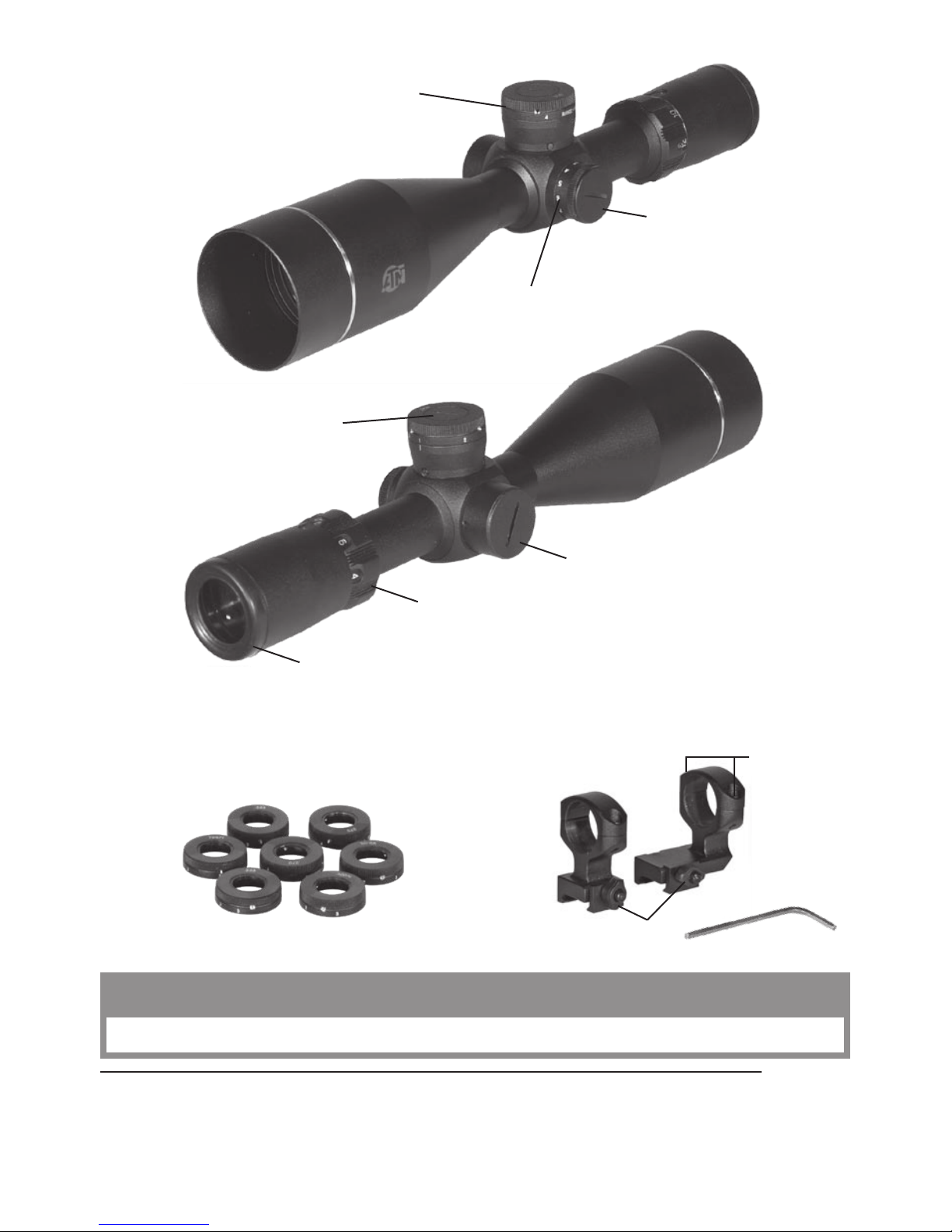
Elevation dust cap
Wind ag e dust cap
Eyepiece focusing adjustment
Magnification adjustment
Mounting rings
Bullet drop compensator
with interchangeable cams
12-position rheostat
Bat ter y housi n g dust cap
Th i s pro d ucT c o nTains n aT ur a l rub b er laTex w h i ch may cau se all ergic r e acT i o n s.
The information in this manual furnished for information use only, is subject to change without notice, is not to be
cons t rued a s a comm i t ment by ATN C orp.
ATN Corp. assumes no res p o nsibili t y or li a b ility f o r any error s or in a c curacie s that may a p pear i n this b o ok.
©2008 ATN Corp. All right reserved.
Fixing screw
Special tool for
d r a w - s c r e w s
Interchangeable cams for
bullet drop compensator
Draw-screws
CAUTION:
Page 3
2
Features:
• Bullet drop compensator with interchangeable cams (except 5x3 3L)
• Mount ing rings includ ed (except 5x33 series)
• Illuminated Reticle with an 12 positi on rheostat
• Step Range Finder
• 1/ 8 MOA at 10 0 Yards
• All glass multi- coated o ptics
• Extra large objective lenses
• Prosheild and Everlight Lens coatings
• Suns had e
OPer atING:
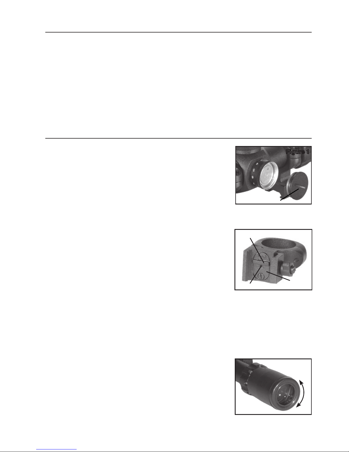
Battery INstallatION:
In s t all the b at ter y into t h e housing w ith the p o l arit y order a s shown on
the battery housin g cap. Bat t er y Type: 3 Volt L ithium standard watch
battery type CR2032 (Fig.1) .
MOuNtING:
Rifl e s c o p e s can be m o u nted util izing 30mm mou n ting rings. ATN mounting rings allow to change the position of the riflescope on the weapon in
relation to a shooter by 1/3 of inch. Thus obtained, such positions are
ad diti o n al to t h e alread y avai l a ble fixe d positions o n the we aver r ail.
Fo r this pu r p o se in th e base of a mounting ring ther e is a ra i l with a fixing pro j e c tion.
In case you nee d to c hange th e posit ion of the rif lescope addition ally pl ease follow the steps mentioned
below for both rings (Fig.2) :
1. Lo o sen the t wo s c rews at t a c h ing the r a il to th e ring.
2. Take the rail out of the groove.
NOTE: If the rail is not taken out easily screw up one of the s crews i nto the
threaded aperture at the middle of the rail until it stops. Then carefully conti n ue ro tating of the s crew until i t pushes out a rail from a groove.
3. About-face the rail.
4. Put the rail into the groove.
5.
Fi x the rail with the t wo s crews.
Fo r mountin g the rifles c o p e on the w eave r rail:
1. Lo o sen the f i xing screws on the s ides of t h e mounting r ings.
2.
Pl ace the rif l escope on the weaver rail s o that t h e projection of the r a il, which i s in the b ase of t h e ring,
enters the r e c e s s in the rail.
3. Tighten the fixing screws of the mounting rings.
CAUTIO N : B e sure gun is not load ed. Use safe g un handli n g pro c edure s all th e time.
FOcusING:
Whi l e holding t h e scope about four in c hes from yo ur eye, quickly glance thro u g h the eyepiece at a
featureless, flatly lit bright area such as a wall or the sky.
CAUTION: Viewing the sun can cause serious eye injury, never look at the
sun with t his product or even the naked eye.
If the reticle is not v i s ible sharply turn the eyepie c e (either direc tion) a
few turns (Fig.3).
Quickly glance through the scope again. If the focus has improved, but
is still not perfect, continue focusing. If the focus condition become
wo r s e turn t h e focus oppos i te directio n .
NOTE: Unlike other sights, 12-36x80 has additional system for focusing
wh en shooti ng at s m all dist ance (Fig .4).
Figure 2
Fixing projection
Threaded aperture
Rail
Figure 3
Battery housing cap
Figure 1
Page 4
3
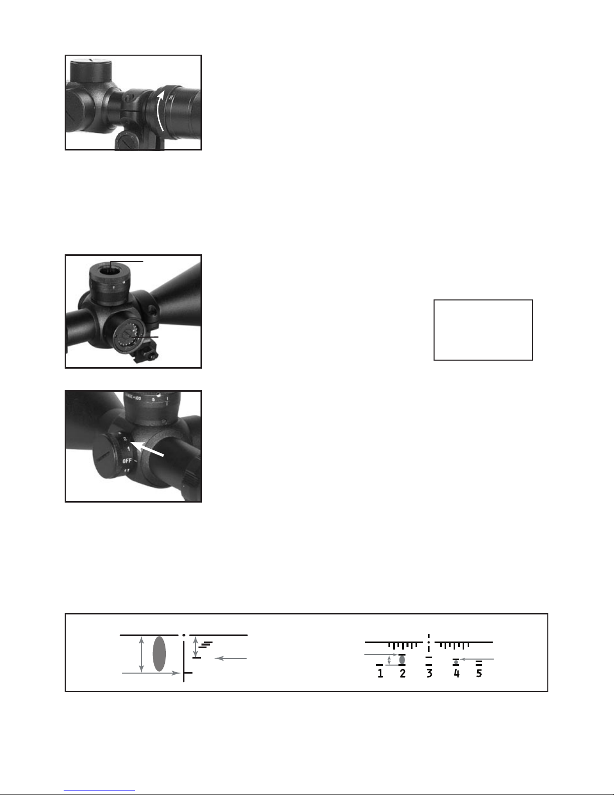
Fo r shooting at the d i stance up to 10 0 yards - t urn focusin g ring in t he direction to the m a r k 10 0 m
against stop.
For shooting at the distance over 100 m turn the focusing ring in the direc-
tion to the mark ∞ against stop.
Pre-zerOING:
Pre -ze roing is r e c o mmended and c a n be done w i th a scope g u ide or bor e
sight.
CAUTION: Be sure gun is not loaded. Use safe gun handling procedures
al l the time.
zerOING:
CAUTION: All shooting should be done at an approved range or other safe areas. Eye and ear protection
is recommended.
Danger: If you used a bore-obstructing device, remove it before proceeding. If the barrel has-been drilled
for a mount, check that the screws do not protrude into the bore. Do not fire live or even blank ammunition
with an obstructed barrel. An obstruction can cause serious damage to the gun and possible personal injury
to yourself and others nearby.
From a s teady res t position, fire thr e e rounds a t a 100 yar d target.
Observe bullet strike on target and adjust windage and elevation screws
as needed to correct aim. You will need to
remove the dust caps from the top of the
windage and elevation adjustments to do
this (Fig.5).
NOTE: Each click of adjustment changes
bullet strike by the amount shown on the
chart below.
When you have fi n ished zer o ing, repla c e
windage and elevation dust caps.
electrONIc retIcle:
You r scope has an Electro n i c reticle. There a re 12 positions of brightness. The rheostat is manipulated by the knob located at the back of the
scope. It is l abelled wit h numbers fr o m 0 to 11. When t he rheostat is set to
0 you will see a bla c k etched r eticle. The reticle wi l l light u p red electro n i c ally as you rotate the rhe o s tat thro u g h the num b er s, 11 being the
brightest (Fig.6).
usING the atN raNGeFINder retIcle:
The r a n ge f i nd e r r eti c le i n y o ur s c op e w a s de s ig n e d to a s sis t y o u in d e t e rm i nin g t he r a n ge o f y o u r tar g et .
The s e di s t an c es a r e bas e d on a 6 ’ tar g et , i f a 6’ t a rg e t f it s b et w ee n t h e nu m be r e d ba s el i n e (t h e fi v e s hor t
horizontal lines and the post of the reticle above the baseline determines your distance. If a 6’ target
fits between the horizontal post of the reticle and 2 the target is 200 yards away. If the same target fits
between the 4 and the horizontal post of the reticle the target is 400 yards away. The same is with the 6
and 10. The target would be either 600, 800 or 1000 yards away (Fig.7).
NOTE: The 5x33 series and the 2-6x40 utilize a range finder based on a three foot target.
Figure 4
Figure 6
Windage/Elevation
(inches of movement per click)
50 Yards - 1/16”
100 Yards - 1/ 8 ”
200 Yards - 1/ 4 ”
300 Yar d s - 3 / 8”
Figure 5
Elevation
Windage
Figure 7.
If a 6’ tar get
fits between
these two
li n e s t h e n
the ta rg et is
20 0 y a r d s
away.
If a 6’ tar get
fits between
these two
li n e s t h e n
the ta rg et is
40 0 y a r d s
away.
If a 3’ tar get
fits between
these two
li n e s t h e n
the ta rg et is
20 0 y a r d s
away.
If a 3’ tar get
fits between
these two
li n e s t h e n
the ta rg et is
40 0 y a r d s
away.
2
4
10
6
Page 5

4
Bullet drOP cOMPeNsatOr:
Yo u s ho ul d h av e z er oe d y o ur s co pe at 10 0 ya rd s. W he n s ho ot in g a t l on ge r
ranges the bullet drop compensator should be adjusted for 200, 300,
400, and 500 yards ( and 1000 yards for 8-24x65LU and 12-36x80LU).
Depending on the distance click the bullet drop compensator to the
ap p ro pr ia t e se t ting . Th i s w il l a ut o ma ti ca ll y ad ju s t yo ur r e ti cl e f o r t h at p ar-
ticular d i st anc e. Your s c o p e also comes with o t h er cams allow i n g you to
change your bullet drop compensator to work with the different rifles.
NOTE: 12-36x80 has special mechanism for bullet drop compensation
with compensator for .50 BMG. Compensator provides shooting at the
dist ance from 200 up to 3000 yards. (See page 7 for instu ctions.)
To set the necessary distance combine the figure with the mark on the immovable upper part of the
mechanism.
chaNGING the Bullet drOP cOMPeNsatOr
Set the bullet drop compensator to the 100 -yards (5x33LU, 2- 6x40LU,
3-9x55LU, 4-12x60LU) or 200 yards (4-12x75LU, 6-18x65LU) range.
Then remove the elevation dust cover. Next you will find three small set
screws on the bullet drop compensator right above the yardage numbers.
Remove these screws and lift the cam off of the scope. (Fig.9) On c e you
have done this select the desired caliber cam you would like to use and
place this cam where you removed the previous one (make sure that a
replacement cam is set to the 100-yard range for 5x33LU, 2-6x40LU,
3-9x55LU, 4-12x60LU and 200 yards for 4-12x75LU, 6-18x65LU). Then
tighten the cam by putting the three set screws back. Finally place the
dust back.
retIcle systeM:
Upon initial use of the ATN Professional Variable Power scope you may notice a somewhat unusual
behaviour o f the ret i c l e syste m. One, the reticle will incre a se or decre a se with t h e power change. Two,
the reticle will move from the center when you adjust windage and/or elevation. These are not defects.
As the name implies, our main goal while designing this line was to provide the customer with the most
accur ate and reliable s i g hting sy stem in t he world. In order to achieve this , we had to depar t fr o m the
mor e “conve ntional” designs that the American consu m er s are s o familiar with.
retIcle chaNGING sIze:
In any optical design the reticle has to be placed either in the front focal plane or the rear focal plane
(the only exception to this rule are the Shepherd scopes that contain two reticles, one in each plane).
The rear focal plane, or behind the magnification module, was the initial and less complicated, as well
as less expensive solution. Up to this day, almost all American scopes and inexpensive imports uti-
lize this design. However, there is an inherent flaw in this type of system. Because the magnification
module is housed within sliding mechanical parts, some tolerance for lateral and vertical movement has
to be allowed. Therefore, when the power is changed the point of impact may shift as much as several
inches. A more reliable design is to place reticle in the front focal plane, i.e. in front of the magnification
module. In this situation movement of the module will have no effect on the point of impact. The reticle
will increase/decrease in direct proportion to magnification, i.e. if you change the magnification from 6x
to 18x , t h e image is in c rease d t h r e e time s a n d the reti c le alon g w i t h it. Th e s i z e of t h e r e ticl e i n r e latio n to
size of t h e target w ill not c h ange. The point of impact rem a i ns constant at all t imes.
MOvING retIcle
A somewhat similar situation take place with windage and elevation adjustments.
Most of the American scopes and low-priced imports adjust the front tube for windage and elevation.
This action moves the whole image while the reticle remains in apparent center. While aesthetically
appea ling, this system lacks inh e rent accur acy.
In the Professional series, windage and elevation adjustments are effected by moving the reticle itself.
Sinc e i n o u r system the o b j ec t i ve lens is f i x e d , there wi l l n e v e r b e any distor ti o n , w hic h m ay a p pear whi l e
moving the front tube of the scope. Further more, since the reticle weighs only a few grams, it allows
for extremely precise (1/8” at 100 yards), reliable, and repeatable adjustments. The optical effect of
this system is that the reticle will not be located in the center once sighting in has been accomplished.
This situation can be remedied however through the use of vertical and horizontal shims available any
gunsmith.
Figure 9
Bullet drop
compensator
Figure 8
Page 6

5
the atN adjustaBle rINGs
ATN adjustable rings (Fig.10) have rotatable inserts which allow for as
much as 20 Minutes of Angle, or approximately 20 inches at 100 yards,
mounting adjustment without touching the scopes internal windage
and elevation mechanisms. This in turn allows the user to maintain the
scopes center of optical axis when performing the initial installation of
a new ATN rifle scope. This feature is extremely important in eliminating paralla x and maintaining a centered reticle with application of these
units, while offering greater overall zero range selectivity.
Each ATN scope is furnished with a set of non-of fset rings useable with
any Weaver or Picatinny style mount. These may also be reversed for
more inter ring distance options or the recoil lug on the underside of
each ring can be reversed (turned 180 degrees) by removing the two screws attaching it to the ring.
Additionally, we offer an offset ring that when coupled with either standard or extended bases, will allow
proper mounting on most any production or custom act i o n . T h e r i n g s p r ovided with your s cope have t h e
corr e c t height t o allow for the n e c essar y bell clea rance requir ed.
INstallatION
The Select the appropriate bases for your application. These can be 2 piece, one piece or rail. When
installing the bases be sure and use Locktite or an equivalent thread locker on the mounting screws.
Most bases install with 6-48 screws and these should be torqued to about 22 inch/lbs. Generally all
receiver/base combinations have some degree of misalignment. However, this is not a problem with
the ATN rings as this is easily compensated for by the floating ring inserts, assuring a stress free scope/
mount/receiver combination, another important accuracy consideration.
At tach t he rings to the base s and determine if you have the r i g ht distance c e nter to center.
The rings must not be closer than 1/8 inch to any place here the scope transitions from the 3 0 mm main
tu b e includin g the tu rret area. Clos er than 1/ 8 inch may cause turret or variable po wer ad justment bind-
ing. The available offset ring has 1 inch of distance form the center of the ring and used with or without
extension base(s), if necessar y, should easily cover all base mounting
or eye relief problems. Tighten the ring securing side nuts finger tight.
Remove the tops of both rings and inserts and cradle the
scope in their lower halves. Install the top halves and tighten
each ring’s four screws to finger tight ( Fi g.11 ) . Do not over
tighten or you will be unable to rotate the offset inserts.
The use of a bore sight or collimator at this stage is very helpful setting
the initial alignment of scope and bore. This can also be accomplished
Figur e 11
The table below provides the minimum focusing distances for our variable riflescopes. As you are aware,
due to their highly advanced design, our scopes have no parallax. But if they were focused to the distance
below minimal, a parallax-like effect (i.e. target in focus while reticle is not, or vice versa) will appear.
UNIT 2-6x40 3-9x55 4-12x60 6-18x65 8-24x75 12-36x80
2x 1 4(3x)
4x 10 10( 5x) 6
6x 20 17(7x) 20 12
8x 25(9x) 30 25 25
10x 60 50 50
12x 80 80 80 40
14x 115 115 50
16x 130 130 60
18x 150 150 70
20x 180 80
22x 200 90
24x 220 100
26x 110
28x 120
30x 130
32x 140
34x 150
36x 160
Fig u r e 10.
Page 7

6
by placing a well-lit and defined bull’s-eye target with at least a 6-inch
black, 100 yards from a sand bagged and well suppor ted rifle. Using the
10 0 -yard distanc e to targ e t w i l l g i ve a co nvenient zero but other distan c e s
can be used. It will, however, require more adjustment during live fire to
ac h ieve a 10 0 yd. zero. Sighti ng thru the bore with t h e action open center
the black bull’s-eye in your rifles bore. You would like the black circle of
the bull’s-eye centered in the scop es field of vi ew wit h the cr osshair in the
cent er of the b ull. If i t is not, f irst use the s id e nuts that secure the r i n g s to
the bases to adjust the scope to zero windage (Fi g.12 ).
Alternately loosening and tightening the side nuts while checking the
bores alignment will move the scope crosshair accordingly:
Looking from behind the scope in normal shooting position.
Loosening the rear rings left side nut and then retightening the right side
will move the crosshair to the left. Reversing this procedure will move the
cros s h air to t he right.
Ad j u stment usi n g the fro nt rings scr ews will result i n the opposit e.
Loosening the front rings left side nut and tightening the right will move the
cros s h air to t he right.
Nex t c heck the e l evat i o n for zero. If the c r osshair i s not cen tered a d just it
by rotating the a centric inserts via the following method:
Us e the slo t milled into t he top h alf of each ring to acces s the hole s drilled
thru the insert ( F i g .13 ) . Move the inserts radially to achieve the above
described scope picture by inserting a round rod into the holes drilled in
the insert (Fig.14 ) . The shank (blunt end) of a 9/ 64 drill works per fectly.
When the reticle is centered, tighten the ring screws exerting torque on
the short end of the supplied allen wrench. It is not necessary to use the
levera g e of t h e l on g a rm t o t ig h t e n th e s cr e w s any m o r e th a n an ad d it i on a l
1/8 turn.
sIGht IN yO u r rIFle
Chances are your rifle will not shoot to your bore sighted zero or to the zero you desire. This is primarily
due to the rifles recoil impulse prior to the bullets departing the barrel. Recoil for RH twist barrels tends
to carry th e shot up and to th e left. If you are more than 1 i nch in any d irection from t he center of the b ull
or from your desired zero, adjust the scope using the rings insert mechanism or the rings side nuts as
de s cr ib ed a bo v e . It i s al w ays b e st t o l o os en t he t o p h a lv e s o f t he r in g j u st e no u gh to a l lo w fre e ro t at io n or
pi v o ti ng o f t h e i n se rts s o th a t s t re ss i s n o t i n tr od uc ed by a n y c h an ge s. O nc e y o u h a v e ze r oe d yo ur, wi n dage retighten the side nuts and pro ceed to fine-tune the elevat ion. Both rings have 10 MOA adjustment
vi a the inser t. You w ill n ote that each i nsert h as a t hick and a t hin side that al low a centric orientation of
the s c o pes body in the rings. T he scope’s elevation m ay be a d justed as follows :
Placement of the thick side at 6 O’clock in the rear ring will result in raising the crosshair 10 inches at 100
yards. Conversely placing the thick side at 12 O’clock will lower it 10 inches. Again similar adjustments
of the front ring’s insert will have an opposite ef fect; the thick side at 6 O’clock will lower the impact 10
inches at 10 0 yards. T h e refore, placement of the thick side of the rear ring at 6 O’c lock an d the front’s at
12 O’clock will raise the impact a maximum of 20 inches at 100 yards. Any combination from 0 to 20 MOA
is possible depending on the orientation of the inserts in tandem.
Note: Any orientation of the inserts such that the thick sides of the inserts are not vertical, i.e., not at 12 or
6 O’clock, will result in a windage change in addition to elevation. In this case, once elevation has been
ac hieved a final windage adjustmen t must be carried o ut using the sid e nuts a s descri bed above.
Once your basic zero is set you can now use the scopes internal adjustments to fine tune impact to any
sho oting cond i tion wi th the c o nfidenc e that your optics are free of accurac y rob b i ng parallax and stress.
MaINtaINING yOur rIFlescOPe:
Your rifle scope is waterproof and shockproof. However, you should never try to take apart or clean it
inter nally (it will void your warranty) . If your scope ever d oes n eed a ny repair or adjustment, it should be
returned to ATN’s service department. Optical surfaces will perform their best if they are wiped clean
from tim e to t ime wi th a l ens tis sue or with o ptical qualit y l ens pa per li ke th ose for eyeglas ses or camera
lenses. Maintain the metal surfaces of your rifle scope by removing any dirt or sand with a soft brush so
as to a v o id s cr at c hi ng t he f in i sh . Wi pe d ow n th e sc op e wi th a s li g ht ly w e t c l ot h an d fo l lo w wi t h a d ry cl o th .
Finally, going over the tube with a silicone treated cloth will restore luster and protect the scope against
corr o s ion. Be c a reful no t to to u c h the lense s with the silicone clot h.
Fig u r e 12
Fig u r e 13.
Fig u r e 14 .
Page 8

7
Base MOuNt FOr 12x36
Base Mount fo r 12 x 3 6 was developed fo r extreme r ange rifles like t h e 50 BMG. W i th 300 MOA of elevation, ranging in access of 3000 Meters is possible. Used in conjunction with a scope internal adjustments t h ere are thr e e m od e s o f vert i cal a n d t wo m o d es of h o r izont a l a d jus t m ent . I t i s i mpo r ta n t t o i nst a l l
the riflescope with the reticle’s convergence point on the center of the scopes optical axis. Along with
the elevation capabilities there is also more than enough windage adjustment in the base to accomplish
this task, regardless of base or installation range requirements. There are several mounting systems
available t hat fac i litate t h is, but n o ne other than Base M o unt for 12 x 3 6 t h at allow this at extreme r a nges.
Thes e instructions are intended to h e lp you t a ke ful l advant age of th i s remarkabl e mount.
INstallatION
Base Mount for 12x36 requires Picatinney or slotted weaver style base for attachment to the firearm. It is
important to keep from over tightening the both the rail
screws and the ring screws (Fig.15) . The large bearing
surface on both allows minim a l tor q u e o n t h e s c r e w s . It
is r ec omm en ded t o g r ip th e s ho rt e nd of a n a ll en wr enc h
to apply torque so that torque is minimized on the ring
screws, then add another 1/8 turn utilizing the long end
of the wrench. The mounting wing nuts can be tightened adequately using a pair of needle nosed pliers.
Once mounted on the rifle install the scope in the rings
using the above described torque technique applied in
a figure 8 pattern. Be sure that the scope’s crosshair is
squar e w i th the re c eiver a n d bore. A bor e s i ght h e l ps to
both align the X-hair and in the below described initial
adjustment of the scope.
As stated earlier it is v e r y impor tant to c enter the scopes opti c al axis for long range sho o t i n g , t h u s a l l ow-
ing minimal optical distortion. The vertical and horizontal positions of the retical want to be centered in
their respective travel range. Typically this initial zero is then adjusted to the desired point of impact for
the chosen ammunition using the scopes internal adjustments. While this is an acceptable and widely
used practice the end result is to remove the X-hair from the center of the optical axis, even when using
a scope that has a self-centering reticle. The self-centering refers to the position of the reticle in the
scopes field of view not its position relative to the optical axis. Using Base Mount for 12x36 impact can
and should be used to for initial sighting in or zero. Ideally this should be done at 200 yards or 100 yards
if t he ballis t i c cur ve fo r your c h o sen ammo i s known.
Referring to Figure use the following sequence:
1. Check the w i n d age for zero. If the cro s s h air is no t centere d adjust it by rotating the a centric inserts via the following method: Use the slot milled into the
top half of each ring to access the holes drilled thru the insert) (Fig.16 ) . Move
the inserts radially to achieve the above described scope picture by inserting a
round rod into the holes drilled in the insert (F i g.17) . Th e shank ( blunt e n d ) of a
9/64 drill works perfectly. When the reticle is centered, tighten the ring screws
exerting torque on the short end of the supplied allen wrench. It is not neces sar y t o use t h e leverage of the l ong arm to tigh ten the screws any more th an an
additional 1/8 turn.
2. Set Ballistic Cam (BC) “A” (Fi g .18 ) on position 2 (200 Yards) by locking the
BC Lock Lever (BCL) “C” in the down position and turning it full CW as viewed
from above.
3. Lock out BC by placing the BC Lock “C” in the up position and run the mount’s
Main Vertical Adjuster (MVA) “B” to its lowest setting by turning it full CW, also.
The mount is n ow positio n e d for i n itial sight in at 20 0 yards.
4. Using the following graduations sight scope in for 200 yard zero utilizing only the mounts adjusters
“B” and “ D”.
Rail screws
Ring screws
Ring screws
Fig u r e 15.
Fig u r e 16.
Direction Mount/External (Coarse) Scope/Internal (Fine)
Elevation (Vert.) “B” 3 M OA / Click 1/ 8 MOA / Cl i c k
Win d age (Hori z.) “ E” 0-2 0 MOA 1/ 8 MOA / Cl i c k
Page 9

8
Absolute zero may not be attainable with “B” due to
coarseness of clicks, but get as close as possible.
Both rings have 10 MOA adjustment via the insert.
You will note that each insert has a thick and a thin
side that allow a centric orientation of the scopes body
in the rings. The scope’s elevation may be adjusted
as follows: Placement of the thick side at 3 O’clock in
therea r r ing will result i n s hif t i n g l ef t ward t h e c r o s s h a ir
20 inches at 200 yards. Conversely placing the thick
side at 9 O’clock will shift it 20 inches to the right. Again
similar adjustments of the front ring’s insert will have
an opposite effect; the thick side at 3 O’clock will shift
the impact to the right 20 inches at 200 yards. There-
fore, placement of the thick side of the rear ring at 3
O’clock and the front’s at 9 O’clock will shift the impact to the lef t a maximum of 40 inches at 200 yards.
Any combinati o n from 0 to 20 MOA is po s s i ble depending on the or i e ntation of the inse r ts i n tandem.
Note: Any orientation of the inserts such that the thick sides of the inserts are not horizontal, i.e., not at
3 or 9 O’clock, will result in a elevation change in addi-
tion to windage. In this case, once windage has been
achieved a final elevation adjustment must be carried
out using the side nuts as described above.
WARNING ! Tighten each ring’s four screws after each
adjusting before shooting!
5. Using the scope’s internal vertical adjuster (center
turret) finalize your 200 yard zero. Remember you do
not want to move the reticle if possible, but 1 to 11/2
MOA is not critical. If your scope’s clicks or graduations
are 1/ 8 in c h @ 100 ya r ds ( o r ¼ @ 20 0 ) t h is w o uld b e n o
mor e than 8 to 12 clicks e l evati o n.
NOTE: One MOA, or Minute of Angle, is basically 1 inch at 100 yards, 2 inches @ 200,
3 i nc hes @ 3 00, etc.
You r Scope and ATN LR M o u nt are now set for use.
use
Properly used your scope’s reticle will now remain centered on its optical axis if the following shooting
pro c e d u re is use d .
Normall y o n l y t h e ve r ti c al or elevat ion fine adju s t e r ( i n t e r nal scop e ) i s u s ed to fine-tun e i n d ividua l s i g h t ing. Windage is best done with reticle assisted “hold off”. The reason for this is that it is relatively easy
to remember e l evati o n adjustment s, but s o m ewhat h arder to keep tra c k of windag e.
Out to 10 00 Yards
Engage BCL “C” and use the integral Ballistic Cam to adjust elevation zero in 100 yard increments.
Use scope’s inte rnal (tu rret) ad justments to fine tune.
Beyond 10 0 0 Yar d s
Disengage BCL “C” and use LR Mount’s MVA “B” to acquire range. Fine tune using scope’s internal
adjustment.
There are other mounts that allow some initial vertical and horizontal positioning, but none that offer the ability to maintain the center of optical axis on the fly and
over the degree of elevation required for shooting at ranges out to 3000 Meters, that
Base Mount fo r 12 x 3 6 does.
Figure 17.
A. Ballistic Drop
Compensator (BDC)
B. Elevation
Adjustment
Ring
C. BDC L o c k
Lever
D. Rotatable
Inserts
E. Ring S c r ews
Fig u r e 18.
Page 10

9
Model 4-12x60LU 6-18x65LU 8-24x75LU 12-36x80
Magnification 4-12x 6-18x 8-24x 12-36x
Objective Diameter 60 mm 65 mm 75 mm 80 mm
FOV 5°-2° 3. 3 °-1.5° 2.2°-1° 1.5°- 0.67°
FOV@100m(feet) 26.4-10.2 17.4 -7.8 11.4-5.4 7.8 -3 .6
Mounting
30 m m Rings
( included)
30 mm, Ajustable
Rings (included)
30 mm, Ajustable
Rings (included)
Long Range
Mounting System
Bul l et Drop Calibers*
223 , .270, 30 - 06,
.300 Win Mag,
.308, 7mm M ag,
.22-250,
.270, 7mm Mag,
30- 0 6 , .300 Win,
Mag , .308
.22-250, .243,
7mm Mag, .30 - 06,
.300 Win Mag,
.50 BMG
.50 BMG
Rangefinding 1000m 1000m 2000 m 3000 m
Illuminated Reticle Yes Ye s Yes Ye s
Length 370 mm 453 m m 428 m m 500 mm
Width 73 mm 8 4 mm 75 mm 85 mm
Height 61 mm 6 0 mm 92 mm 85 m m
Weights 1.2 kg 1.3 kg 1.5 6 kg 1,8 kg
Eye Relief 90 m m 115 mm 9 0 mm 90 mm
Bat te r y L i fe 100 Hours 100 Hour s 100 Hours 100 Hours
Power Source
3v CR2432
(included)
3v CR2432
(included)
3v CR2432
(included)
3v CR2432
(included)
Sunshade Yes ( 71m m ) Ye s ( 7 3 mm) Yes (85mm) Yes (88mm)
Recomended Use* T,B G ,V T,V T,V S50
Adjustment Windage
and Elevation at 100 m
1 c l i c k = 1/ 8 MOA
Model 5x33L 5x33LU 2-6x40LU 3-9x55LU
Magnification 5 5 2-6x 3-9x
Objective Diameter 33 mm 33 mm 40 mm 55 mm
FOV 4° 4° 10°-3,2° 7°-2,2°
FOV@100m(feet) 21 21 52. 2-16.8 36 . 6-11. 4
Mounting
30 mm Rings 30 mm Rings 30 mm Rings
( included)
30 m m Rings
(included)
Bul l et Drop Calibers*
.223
.223, .270, 30-06,
.300 Win Mag,
.308, 7mm M ag,
223, .270, 30-06,
.300 Win Mag,
.308, 7mm M ag,
223, .270, 30-06,
.300 Win Mag,
.308, 7mm M ag,
Rangefinding 500m 500m 50 0 m 1000 m
Illuminated Reticle Yes Ye s Yes Ye s
Length 263 mm 285 mm 268 mm 332 mm
Width 58 mm 58 mm 75 mm 75 mm
Height 58 mm 70 mm 72 mm 79 mm
Weights 0,55 kg 0,65 kg 0,8 kg 1,0 kg
Eye Relief 75 mm 75 mm 90 mm 90 mm
Bat te r y L i fe 100 Hours 100 Hour s 100 Hours 100 Hours
Power Source
3v CR2432
(included)
3v CR2432
(included)
3v CR2432
(included)
3v CR2432
(included)
Sunshade No No Yes ( 50 m m ) Yes (64 mm )
Recomended Use* Tac, S G Tac,SG Ta c ,WFB Ver
Adjustment Windage
and Elevation at 100 m
1 c l i c k = 1/ 8 MOA
123123
6
7
8
9
123123
*Cams included
**Tac=Law Enforcement, BG= Big Game, DG= Dangerous Game, SG= Small Game, T=Target,
V=Varmint, WFB = wide field brush c o u ntr y, Ver = Versat ile, S50 = spe cialized 50 B m g .
Page 11

10
110 3 2 0 0 8
ONE YEAR PRODUCT WARRANTY
This product is guaranteed to be free from manufacturing defects in material and workmanship under
normal use for a period of 1 (one) years from the date of purchase. In the event a defect that is covered
by the foregoing warranty occurs during the applicable period stated above, ATN, at its option, will ei-
ther repair or r e place the product , an d su c h a c t i on on the part of ATN shall be t he full ex tent of AT N ’s li ability, and the Customer’s sole and exclusive remedy. This warranty does not cover a product (a) used
in other than its normal and customary manner; (b) subjected to misuse; (c) subjected to alterations,
modifications or repairs by the Customer of by any party other than ATN without prior written consent of
ATN; (d) special order or “close-out” merchandise or merchandise sold “as-is” by either ATN or the ATN
dealer; or (e) merchandise that has been discontinued by the manufacturer and either parts or replace-
ment u n it s a r e no t a v a i la b le d u e to re a so n s b eyo n d the c ont r ol of AT N. AT N s ha l l not b e r es p on s ib l e for
any defects or damage that in ATN’s opinion is a result from the mishandling, abuse, misuse, improper
storage or improper operation, including use in conjunction with equipment which is electrically or
mechanically incompatible with or of inferior quality to the product, as well as failure to maintain the environmental conditions specified by the manufacturer. C USTO ME R I S H ER EB Y NO TI FI ED TH AT O P-
ER ATIO N O F T H E E QU IP MEN T DU RI NG DAY LI GH T H OU RS OR U ND ER AN Y E XC ES SI VE LI GH T
CONDITIONS MAY PERMANENTLY DAMAGE THE INTERNAL COMPONENTS OF THE UNIT AND
SAI D DA MAG E W IL L N OT B E C O V ER ED UN DE R T HIS WAR RA NT Y. This warranty is extended only
to the ori g inal pur c hase r. Any breac h o f t h is warra n t y sha l l b e waived unl e ss the c u s tomer n o t ifies AT N
at the address noted below within the applicable warranty period.
The customer understands and agrees that except for the foregoing warranty, no other warranties
written or oral, statutory, expressed or implied, including any implied warranty of merchantability or
fitness for a particular purpose, shall apply to the product. All such implied warranties are hereby and
expressly disclaimed.
LIMITATION OF LIABILITY
ATN will not be liable for any claims, actions, suits, proceedings, costs, expenses, damages or liabili-
tie s a r is i ng o u t of th e u se o f t his p r od u ct . Op e r at i on an d u se o f t he p r o du ct a r e t he s o le r e sp o ns i bil i ty o f
the Customer. ATN’s sole undertaking is limited to providing the products and services outlined herein
in accordance with the terms and conditions of this Agreement. The provision of products sold and
services per formed by ATN to the Customer shall not be interpreted, construed, or regarded, either
expre s sly o r i m pl i e d, a s b e in g f o r t he b e n efi t o f o r creat i ng any ob l ig a t i on to w a r d any th i r d par ty o f l eg a l
entity outside ATN and the Customer; ATN’s obligations under this Agreement extend solely to the
Customer. ATN’s lia bilit y here under for damag e s, reg ardless of the form or ac tion, shall not exce ed t he fe es or o th er ch ar ge s p ai d to ATN b y th e c u st om er or c us to m er ’s d ea le r. AT N s h al l n o t,
in a n y eve nt , b e l ia bl e f o r s pe ci al , i nd ir ec t, in c id en ta l, or co ns eq ue nt ia l d am ag es, i n cl ud in g, b ut
not l im i te d t o , l o st in c om e, lo st r ev e nu e, or l os t p r of it , w he th er su ch d am ag es we re f or es eea b le
or not at the time of purchase, and whether or not such damages arise out of a breach of warrant y, a b r e a c h of agreement, negl ig ence, strict liability or any other t h e or y of liabilit y.
PRODUCT WARRANTY REGISTRATION
In order to validate the warranty on your product, ATN must receive a completed Product Warranty
Registration Card for each unit or complete warranty registration on our website at www.atncorp.com.
Please complete the included form and immediately mail it to our Service Center: ATN Corporation,
1341 San Mateo Avenue, South S an Fr a nc isco, CA 94080.
OBTAINING WARRANTY SERVICE
To obtain warranty service on your unit, End-user must notify ATN service department by calling
800-910-2862 or 650-989-5100 or via e-mail ser vi c e@atncorp.com to receive a Return Mer chandi se
Authorization number (RMA). When returning please take or send the product, postage paid, with
a copy of your sales receipt to our service center, ATN Corporation at the address noted above. All
merchandise must be fully insured with the correct postage ; ATN will not be responsible for improper
postage or, missing or damaged merchandise during shipment. When sending product back, please
clearly mark the RMA# on the outside of the shipping box. Please include a letter that indicates your
RMA #, Name, Retur n Addres s, reas o n for ser vice return, C o ntact in format i on such a s vali d telep h one
number s a n d /or e - mail addr e s s and proof of pur c hases th at w i l l h e lp us to est a b lish the vali d s t art d a t e
of the warranty. Product merchandise returns that do not have an RMA listed may be refused or a
significant delay in processing may occur. Es ti ma t ed W a rr an t y s er vic e t i me i s 10 -2 0 bu si n es s d ays .
End-user/customer is responsible for postage to ATN for warranty service. ATN will cover return postage/shipping after warranty repair to end-user/customer only if product is covered by aforementioned
warranty. ATN will return product after warranty service by domestic UPS ground and/or domestic mail.
Any other requested or required shipping method the postage/shipping fee will be the responsibility of
the end-user/customer.
Page 12

For customer ser v i c e and technical s u p p or t, p l ease contact
American Technologies Network Corp.
North American Office
1341 San M ateo Avenue, South San Francisco, CA 9 4 0 80
phone: 800-910-2862, 650-989-5100; fax: 650-875-0129
European Office
phone : 4 4( 0 )870- 0111286, fax: 44( 0 ) 845-3349142
The following countries can use our
to l l free nu m b er 00 800 9102- 8620
Austria, France, Germany, Holland, Italy, Spain, Sweden, Switzerland
www.atncorp.com
 Loading...