

Page 1
7x30
Instructions for use and maintenance
Page 2

Catalogue Index
1. General Overview ................................................................... (2)
2. Technical Specification ......................................................... (2)
3. Construction Specifications ................................................. (3)
4. How to use a Binocular with a military style reticle ....... (6)
5. Binocular and accessories ................................................... (15)
6. How to care for your binocular .......................................... (15)
Page 3

2
1. General Overview
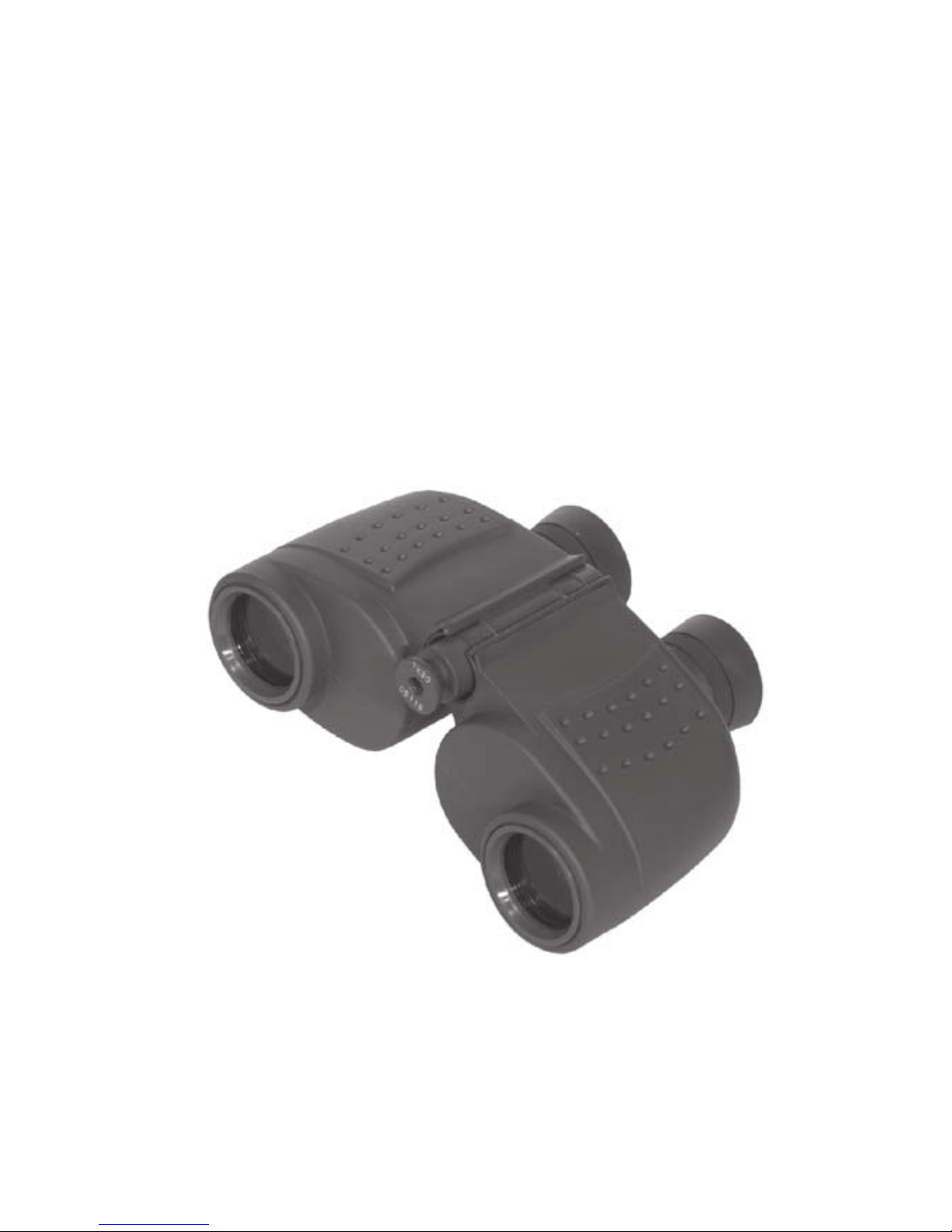
1.1 Main Character
This model of 7x30 binoculars is made to
militar y specifications including a range finding
reticule. The optics are made to exacting militar y
specifications in order to give the viewer excellent brightness, exacting image clarity and unparallel tr ue color of the image whether it is a f lower, bird where color is impor tant or a military
target. The user can have confidence whether it
is being used in a military, public security, traff ic
control, boating, aviation, or any other application requiring confidence of equipment.
1.2 Model 7x30
1. 3 Optimal environment:
-43°C to +55°C: (-40F to +131F)
2. Technical Specification
2.1 Optical performance
Magnif ication: 7x
Field of view: 7.5° (394 ft. @ 1000 yards/360m
@ 1000 Meters)
Exit pupil diameter: 7.1 mm
Exit pupil distance: 21.8 mm (Long eye relief
for eyeglass wears)
Page 4
3
4
Diopter adjusting range: -5~ +7 diopter
Inter pupillary distance: 56-72 mm
Resolution: max 5.5”
2.2 Size and mass
Size (length x width x height) :
174mm X 48mm X 110mm
Weight
Binoculars:max 0.5kg (1.25 lbs)
Complete product: max 1.0kg (2.5 lbs)
3. Construction Specifications
3.1 Optical system
3.1.1 Basic binocular construction
Page 5

4
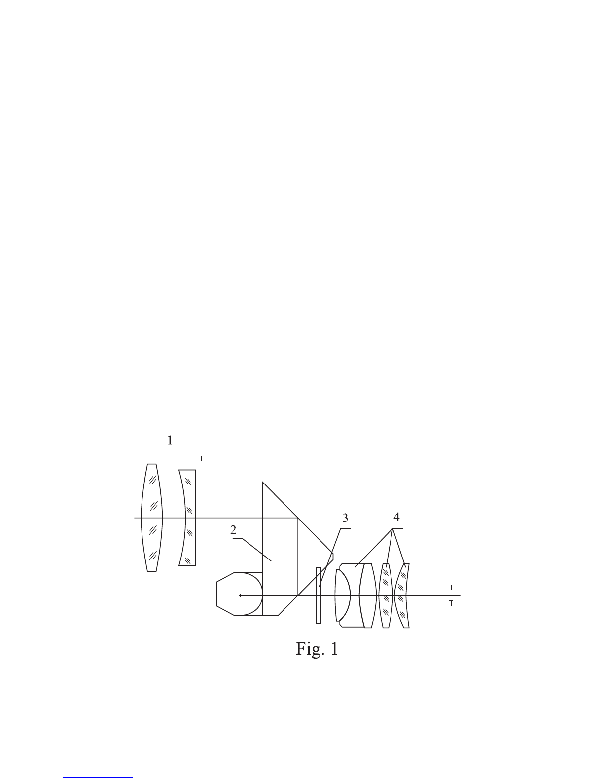
Basic binocular optical construction, as shown
in Fig ure 1, consist of (l) the objective lens, (2)
the erecting prisms, (3) the reticle and (4) the eyepiece. The reticle (3) is build in the right system.
3.1.2 How a Binocular works
The light f rom the object or target you are
looking at enters the binocular through the Objective lens system (item 1, f ig. 1). Due to the objective lens, the image at this point is upside down.
However, as the light rays of the image passes
through the prism system, ( known as the erective prisms) ( item 2, f ig. 1) it becomes right side
up ( erect) and changed f rom r ight to left to lef t
to right so wr itten words appear correct. (Until
this happen the word “word” looks like drow). At
this point the image rays are now passed through
the reticle lens (item 3, fig. 1). The image rays are
now passed th rough the lens assembly (item 4,
fig. 1) so that the obser ver can now see the distant
object.
3.1.3 Reticule (See Fig. 3)
There are vertical and horizontal lines on the
reticule 3. Each small division on both ver tical
and horizontal lines represents 5 mils and each
big division represents 10 mils (one circularity
angle = 6400 mils. (One circular angle equals 1
degree of angle, equals 1 minute of angle, equals
60 seconds of angle, equals 6400 mils.)
Page 6
5
6
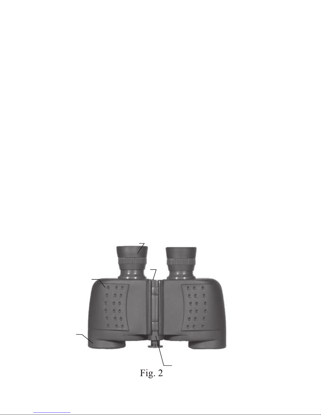
3.2 Body assembly ( Fig. 2)
Figu re 2, illust rates the basic design and
st ructure of a porro prism binocular like
the 7x30. The binocular consists of identical two halves. A right side and a lef t side.
Item 1 is the lens assembly including the special reticle housing. The range adjustment for the
diopter settings is from -5 to+7. Each mark of the
diopter dial on the eyepiece ref lects one diopter
adjustment. Item 2 is the main binocular body
housing the porro prism assembly. Item 3 is the
objective lens assembly where the light from the
image enters the binocular. Item 4 contains the
inter pupillar y disc indicating the set tings that
cor respond to the distance between the obser ver’s eyes. This distance ranges from 56 mm to
72 mm. Item 5 which is on the connecting shaft
2
5
3
1
4
Page 7

6
holding both halves of the binocular is where the
objective lens caps are secure.
4. How to use the binocular.
4.1 How to focus the binocular.
4.1.1 Interpupillary adjustment.
You must first adjust the binocular so that each
eye piece is adjusted to the distance between your
eyes. This is done by putting the binocular in both
hands and adjusting the bino until you basically
see one round image. Note: the image will not be
clear. You will adjust for clarity in the next step.
You must f irst fit the binocular to your eye width
distance.
4.1.2 Adjusting for the use of regular glasses or
sunglasses
This is a long eye relief binocular. It means that
like other binoculars that do not have a long eye
relief you can adjust the flexible rubber eyepiece.
A long eye relief allows the eyeglass wearer to see
a full image instead of a restricted one. If you are
not wearing glasses leave the f lexible eyepiece in
the extended upright position. If you are wearing
glasses then fold down the rubber eyepiece.
Page 8

7
8
4.1.3 Adjusting for image qualit y and clarity.
Unlike some binoculars that have a center
focus to make adjustments this binocular has
individual focusing adjustments. In order for you
to adjust the optics to your individual eyes, you
will need to adjust each eyepiece or ocular. After
placing the binocular at your eyes, you will need
to close you r lef t eye. With your right eye open,
you will need to take the f ingers in your right
hand and adjust the ocular until you see a perfectly clear image of the target you are looking
at. Lower the binocular and remember the diopter
setting for the right eye . Now closing your right
eye, repeat the process you used for the right eye
and turn the left diopter u ntil you have a perfectly clear image. Again, take note of the diopter
setting for the left eye. If, for some reason, the
diopter set tings are moved, such as letting some
other person use the binocular, you will be able to
quickly use (with out adjustments) the binocular
again by setting the right and left oculars to their
correct diopter settings for your eyes.
4.2 How to use the reticle measure azimuth
4.2.1 What is azimuth
The following is the basic def inition of Azimuth. Azimuth of a body is the arc of the horizon intercepted between the nor th or south point
and the foot of the ver tical circle passing through
Page 9

8
the body. It is reckoned in degrees from either the
north or south point clockwise entirely around
the horizon. Azimuth of a cur rent is the direction
toward which it is f lowing, and is usually reckoned from the north point.
A mil’s reticule can measure the azimuth
angle, upper and lower angle, distance and size of
an object or target . The visual distance reticule
lines can measure the distance of normal object
easily on the basis that the object to be measured
is at least 2 meters (6 feet) in height.
4.2.2 How to measure the azimuth angle
The azimuth angle is the angle included
bet ween two objects to be measured at the hori-
Page 10

9
10
zontal direction of the binocular. (Or two ends of
one object at horizontal direction)
4.2.2. A When the azimuth of t wo targets is
smaller than the azimuth measuring range
(-50 ~ +50 mils) inside the binoculars, aim the
scale line at one end of the reticule at the target
then read the value of the scale at which another
target was located on the reticule. The value is
the measured azimuth mil. As shown in fig. 4, the
azimuth of the target (tank) is 0-20 mils. The azimuth between the targets (p-p) is 0-65 mils.
4.2.2.B When the azimuth of two targets
is bigger than azimuth measuring range
(-50 ~+50 mils) inside the binoculars, on the target
can be selected to make the necessar y measurements in a step by step fashion. The sum of the
Page 11

10
value from each step is used to obtain the measured azimuth. As shown in f ig. 5, the azimuth of
target (cr uiser) is 130 mils (60 +70 =130). When
the azimuth of a target is longer than the azimuth
measuring range (-50~1-50 mils) inside the binoculars, you can visually calculate the total azimuth
mils by using the ver tical line on the reticle by
placing the image in a position where the ver tical
line splits the image. You will need to take two
image readings. Mentally, consider the horizontal
with three reference points. Point A is the 50 mil
point on the far left side. Point B is where the vertical line intersects the horizontal line. Point C is
the far right 50 mil point. Now your f irst reading
on the image will be the mils f rom point A to B
with point A on the far left part of the image (see
Fig. 5). Your second reading will be from point
C to point B where point B is now the spot on the
Page 12

11
12
image where point B ended after the f irst reading. Af ter calculating the mils for each image,
You then can add them together to get the total
azimuth read-ing.In the (Fig. 5) image below the
ship is longer than the total 100 mils available on
the reticle. However, by doing the foregoing mil
calculations, you can now obtain the ship’s total
mil azimuth of 130 mils (60 + 70 ).
4.2. 3 Upper and lower angel measurement
Upper and lower angel means the angel included
between any two targets (or two ends of a target)
against the ver tical line on the reticule.
4.2. 3.A Upper and lower angel measurement is
similar to measuring the azimuth. When the upper
and lower angel measurement is ver y small, aim
the cross center of reticule at lower part of the
target, read the scale value at the top of the target.
Page 13

12
The value is the measured mils of angle included
bet ween the upper and lower par ts. As shown in
fig. 6, the value of the lower par t is 40, the angle
included between the upper and lower parts of the
target is 0-75 (75mils).
4.2. 3.B When the target’s upper and lower parts
of the is than the mils on the reticle, it can be
measured in steps and the angle can be obtained
by summing up the value of each step. (The process will be similar to the one that is discussed in
the linear measurements in 4.2.2 B above).
4.2.4 How to use the ret icle to measure distance
4.2.4.A The distance measurement of a target
can be calculated by using the mil reticule.
The formula of distance measurement:
D(KM)≈h(M)/K D (KM) = H (M)/K
D - the distance between the observer and the
target (km)
H - the height of the target (m)
K - upper and lower angle of azimuth of the target
measured with the reticule of binoculars (mil).
When measur ing the distance, f irst, estimate
the height or width of the target, then measu ring upper and lower angle of the target. According, you can calculate the distance between the
Page 14
13
14
observer and the target using the formula. For
example:
There is an adult whose height is 1.70m.
(H= 1.70m)
The upper and lower angle of the adult is 0 - 40
mils (K= 0 - (- 40))
L=H/K= 1.7/40 = 0.0425km=42.5m
Therefore: the distance between the observer
and the adult is 42.5m.
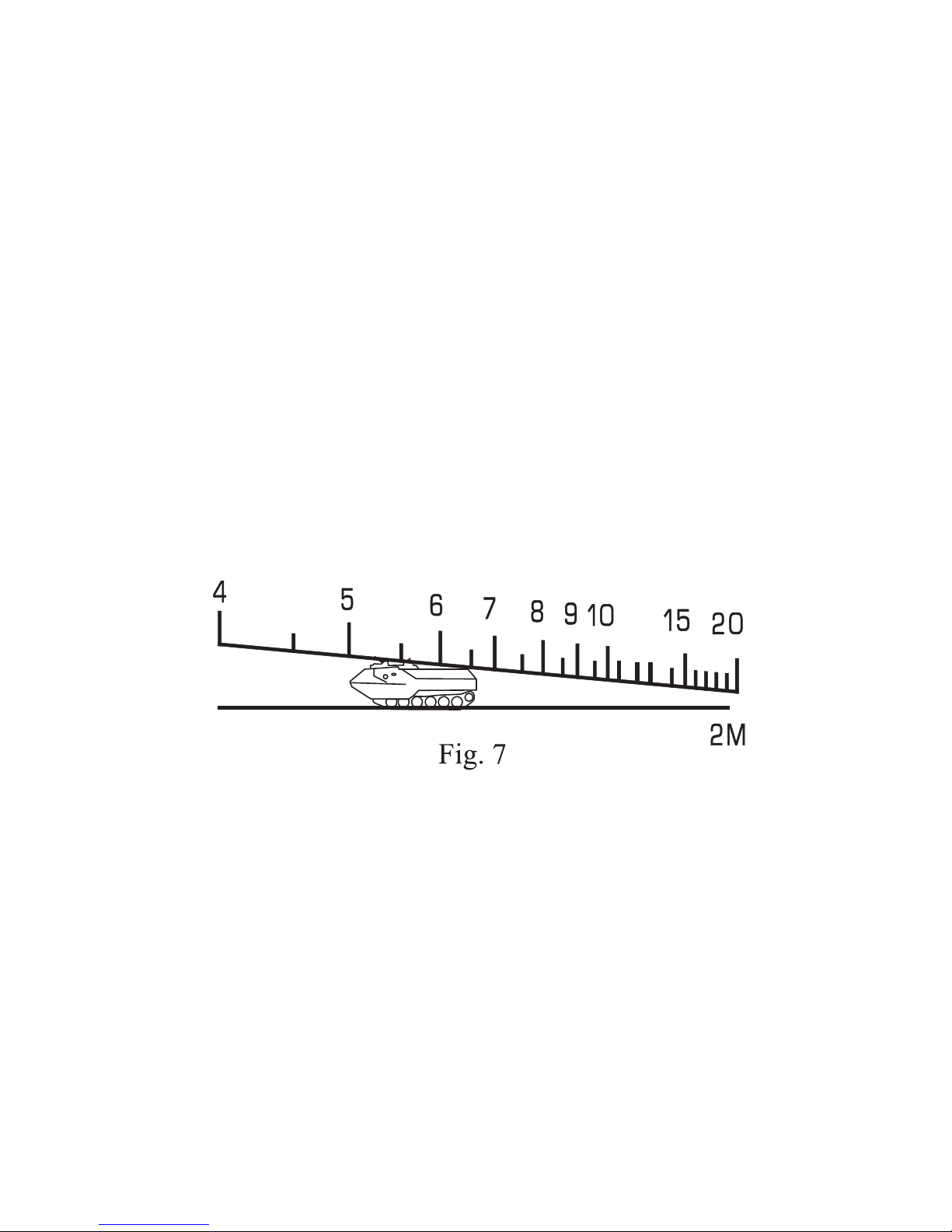
4.2.4.B How to measure distance directly using
the reticle in (Fig. 7)
For example, if the target is 2 meters in height,
place the lower par t of the target at the horizontal line on the reticule with the upper top par t
of the target against the angled scale line. The
reading on the top of the target. Where the top of
the target or image touches the top of the angled
scale line is the distance bet ween the target and
the observer, (line value : 100m)as shown in fig 7,
Page 15

14
the distance between the target and the observer
is 550m.
4.2. 5 How to measure a target’s size (height
and width) using azimuth readings
According to the formula for distance measurement, you can calculate the height using:
H = D x K.
When measuring the size, you first estimate
the distance to the target, then measure the
azimuth or upper and lower angle. With these
measu rements, you can calculate the height of
the target using the for mula. For example: the
distance is 0.6k m between the obser ver and the
target. You can measure that the azimuth is 60
(0-60) and the upper and lower angle is 30 (0-30).
So, using the formula you can get:
The height: H=0.6 x 30 = 18m
The width: h= 0.6 x 60 =36m
4.3 How eyeglass users can use long Eye relief
feature
If you wear prescription glasses or regular sun
glasses, you can still obtain a full image view by
tu rning down the rubber eyecups on each of
the eyepieces or oculars. All binoculars feature
fold down eyecups, but only binoculars, like this
model, feat uring a long eye relief optical system
Page 16

15
16
offers the using a true full feature viewing while
wearing glasses.
5. Binocular and accessories
7x binocular 1 pc
Carrying strip 1 pc
Eyepiece cap 1 pc
Brush 1 pc
Lens cleaning cloth 1 pc
Instr uctions 1 pc
Soft case with car rying strap 1 pc
6. Storage and maintenance
Binoculars are precision optical instrument.
It should be caref ully handled and maintained in
order to keep it in good working order.
6.1 General Maintenance
6.1.1 Lenses: Always clean the lenses after each
use and before you put it back in it’s car rying
case. After each use, br ush any dust or dir t of the
lenses with the special optical brush that came
with your binocular. After brushing, gently wipe
each of the lenses with the special optical cloth.
Never use your finger to wipe the lenses as body
oil will get on the lenses possibly damaging them.
Never use anything to wipe your lenses except
special optical cloths. Always keep your optical
Page 17

16
cloth in the binocular case for easy access for
cleaning.
6.1.2 Although the eyepieces are made to tu rn
for individual eye diopter adjustments, do not
turn them beyond the factory set stop. Forcing it
beyond this point will damage the eyepiece optics
and make the binocular unworkable.
6.1.3 After using, always remember tu rn the
diopter adjust ment to its inf inity position to
avoid any damage of the ocular system in case of
accident.
6.1.4 Avoid any extreme shaking or d ropping
of the binocular. This may damage the inter nal
optics and prisms. Store the binocular in a dr y
and well ventilated place.
6.2 Maintenance
If you f ind that the binocular not working
correctly, do not try to repair it yourself. Trying
to repair it yourself may void any warranty you
have on the binocular. Always, take or send it to
a professional binocular repair st ation. If one is
not readily available, then send it back to the factory.
Page 18

17
18
Page 19

18
Page 20

 Loading...