

Page 1
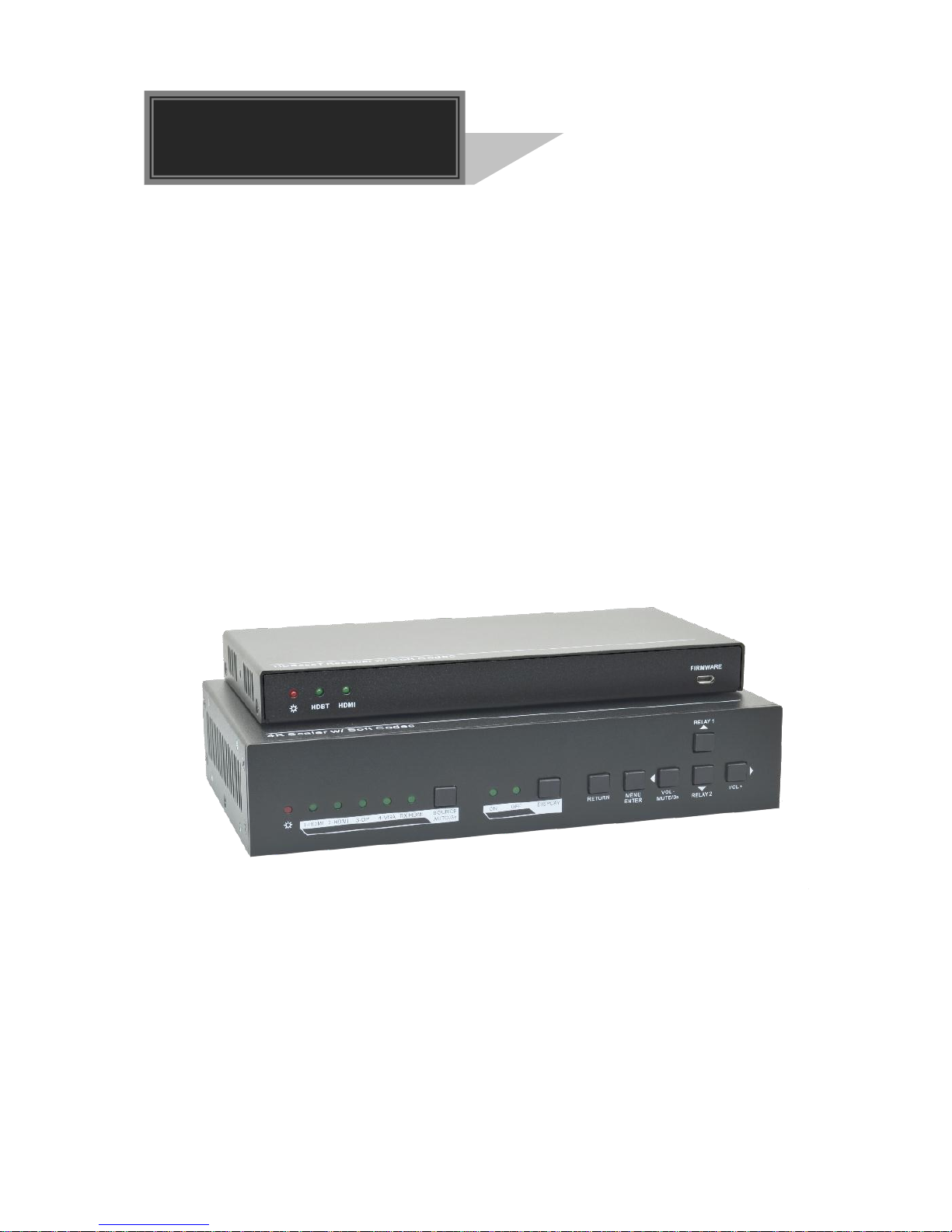
SC41T-CODEC
4K Scaler with Soft Codec
All Rights Reserved
Version: SC41T-CODEC_2017V1.0
User Manual
Page 2

4K Scaler with Soft Codec
Preface
Read this user manual carefully before using the product. Pictures shown in this manual
is for reference only. Different models and specifications are subject to real product.
This manual is only for operation instruction only. The functions described in this version
are updated till August 7, 2017. In the constant effort to improve our product, we reserve
the right to make functions or parameters changes without notice or obligation. Please
refer to the dealers for the latest details.
FCC Statement
This equipment generates, uses and can radiate radio frequency energy and, if not
installed and used in accordance with the instructions, may cause harmful interference
to radio communications. It has been tested and found to comply with the limits for a
Class B digital device, pursuant to part 15 of the FCC Rules. These limits are designed
to provide reasonable protection against harmful interference in a commercial
installation.
Operation of this equipment in a residential area is likely to cause interference, in which
case the user at their own expense will be required to take whatever measures may be
necessary to correct the interference.
Any changes or modifications not expressly approved by the manufacture would void
the user’s authority to operate the equipment.
Page 3

4K Scaler with Soft Codec
SAFETY PRECAUTIONS
To insure the best from the product, please read all instructions carefully before using
the device. Save this manual for further reference.
Unpack the equipment carefully and save the original box and packing material for
possible future shipment.
Follow basic safety precautions to reduce the risk of fire, electrical shock and injury
to persons.
Do not dismantle the housing or modify the module. It may result in electrical shock
or burn.
Using supplies or parts not meeting the products’ specifications may cause damage,
deterioration or malfunction.
Refer all servicing to qualified service personnel.
To prevent fire or shock hazard, do not expose the unit to rain, moisture or install this
product near water.
Do not put any heavy items on the extension cable in case of extrusion.
Do not remove the housing of the device as opening or removing housing may
expose you to dangerous voltage or other hazards.
Install the device in a place with fine ventilation to avoid damage caused by
overheat.
Keep the module away from liquids.
Spillage into the housing may result in fire, electrical shock, or equipment damage. If
an object or liquid falls or spills on to the housing, unplug the module immediately.
Do not twist or pull by force ends of the optical cable. It can cause malfunction.
Do not use liquid or aerosol cleaners to clean this unit. Always unplug the power to
the device before cleaning.
Unplug the power cord when left unused for a long period of time.
Information on disposal for scrapped devices: do not burn or mix with general
household waste, please treat them as normal electrical wastes.
Page 4

4K Scaler with Soft Codec
Contents
1. Introduction ........................................................................................................................................ 1
1.1 Introduction to SC41T-CODEC ................................................................................................. 1
1.2 Feature ..................................................................................................................................... 1
1.3 Package List ............................................................................................................................. 2
2. Specification ...................................................................................................................................... 3
2.1 Transmitter ............................................................................................................................... 3
2.2 Receiver ................................................................................................................................... 4
3. Panel Description ............................................................................................................................... 5
3.1 Transmitter ............................................................................................................................... 5
3.1.1 Front Panel................................................................................................................... 5
3.1.2 Rear Panel ................................................................................................................... 6
3.2 Receiver ................................................................................................................................... 7
3.2.1 Front Panel................................................................................................................... 7
3.2.2 Rear Panel ................................................................................................................... 7
4. System Connection ............................................................................................................................ 8
4.1 Usage Precaution ..................................................................................................................... 8
4.2 System Diagram ....................................................................................................................... 8
5. Button Control .................................................................................................................................... 9
5.1 Manual Switching ..................................................................................................................... 9
5.2 Auto Switching ........................................................................................................................ 10
5.3 Volume Adjustment ................................................................................................................. 10
6. RS232 Control ................................................................ ................................................................ .. 11
6.1 RS232 Connection ................................................................................................................. 11
6.2 RS232 Control Software ......................................................................................................... 12
6.3 RS232 Command ................................................................................................................... 13
6.3.1 Source Switching .........................................................................................................13
6.3.2 Audio Adjustment .........................................................................................................13
6.3.3 Output Resolution ........................................................................................................14
6.3.4 Auto Power-off Setup ...................................................................................................15
6.3.5 CEC Command ...........................................................................................................16
6.3.6 Relay Control ................................................................ ..............................................17
6.3.7 EDID Configuration......................................................................................................17
6.3.8 HDCP Compliance ......................................................................................................17
6.3.9 Device Setup ...............................................................................................................17
7. OSD Control .....................................................................................................................................18
7.1 Picture .................................................................................................................................... 18
7.2 Setup ..................................................................................................................................... 19
8. GUI Control .......................................................................................................................................20
8.1 Control Menu .......................................................................................................................... 21
8.2 Configuration Menu ................................................................................................................ 22
8.3 RS232 Control Menu .............................................................................................................. 24
8.4 Password Menu ...................................................................................................................... 26
8.5 GUI Update ............................................................................................................................ 26
9. Panel Drawing ..................................................................................................................................27
10. Troubleshooting & Maintenance ......................................................................................................28
11. Customer Service ...........................................................................................................................29
Page 5

4K Scaler with Soft Codec
1
1. Introduction
1.1 Introduction to SC41T-CODEC
This SC41T-CODEC is a conferencing system codec kit supporting resolutions up to
4K@30Hz 4:4:4 and HDCP 2.2. It includes Transmitter and Receiver, providing AV
switching, audio de-embedded, and USB extension, plus system control. All video,
audio, control, USB and Ethernet signals can be transmitted over a single CATx cable
up to 100m.
The kit provides four video inputs such as HDMI, VGA and DP. To simplify meeting room
device management, the kit offers LAN for Ethernet and USB ports for devices
extension, four on the transmitter and two on the receiver. It supports a variety of 2.0
USB devices like camera, microphone and keyboard as well as other HID devices.
It also allows users to control system functionality via WEB GUI, RS232 and CEC.
Additionally, users can control the rise and fall of projector screen over relay port.
This is an ideal solution for meeting spaces using PC-based conferencing system
codecs such as Skype@, WebEx@ and GoToMeeting@, etc.
1.2 Feature
Supports resolution converting ranging from 720p to 4k x 2k @30Hz 4:4:4.
Provides a variety of interfaces to simplify room devices management.
Supports PCs, USB devices like keyboard, webcam, MIC for conference system.
Extends the transmission distance of USB signals.
Two type B USB for connection to host, four type A USB for HID devices like
webcam, mic and keyboard.
Supports video source auto-switching function.
HDBaseT technology extend Video, Audio, control command and Ethernet signal up
to 100m.
Ethernet can be imported from either Receiver or Transmitter, providing LAN
accessibility for users.
Audio can be de-embedded out from AUDIO OUTPUT.
Allows connected displays to be controlled via CEC commands or front panel
buttons.
Ensures EDID communication between sources and display.
Relay commands can be triggered to control relay devices such as projector.
The Receiver provides video input port for working with BYOD-W (sold separately).
Page 6

4K Scaler with Soft Codec
2
1.3 Package List
Transmitter
1 x SC41T-CODEC-T Transmitter
2 x Mounting Ears with 4 Screws
4 x Plastic Cushions
1 x Power Adapter (24VDC,2.71A)
1 x RS232 Cable (3-pin phoenix connector to DB9)
Receiver
1 x SC41T-CODEC-R Receiver
2 x Mounting Ears with 2 Screws
4 x Plastic Cushions
1 x 5-pin Phoenix Connector
1 x 7-pin Phoenix Connector
1 x User Manual
Note: Please contact your distributor immediately if you found any damage or defect in
the components.
Page 7

4K Scaler with Soft Codec
3
2. Specification
2.1 Transmitter
Video
Video Input
(2) HDMI; (1) DP; (1) VGA
Video Input Connector
(2) Female HDMI; (1) DisplayPort; (1) Female VGA
(15-pin)
Video Output
(1) HDMI; (1) HDBaseT
Video Output Connector
(1) Female HDMI; (1) RJ45
Output Resolution
Supports 3840x2160@30Hz, 1920x1080, 1280x720
Standards
Compliant with HDMI 1.4 & HDCP2.2
Audio
Audio Input
(1) AUDIO
Audio Input Connector
(1) 3.5mm Stereo jack
Audio Input Impedance
>10kΩ
Control Part
Control port
(2) PC, (2) DEVICE; (1) RS232; (1) TCP/IP; (1) LAN
Control Connector
(2) Type-B USB; (2) Type-A USB; (1)3-pin phoenix
connector; (2) RJ45
General
Transmission Distance
Up to 100m
Operation Temperature
0 ~ +40℃
Storage Temperature
-10 ~ +55℃
Relative Humidity
10% ~ 90%
External Power Supply
Input: AC 100~240V, 50/60Hz; Output: 24VDC 2.71A
System Power Consumption
40w (Max)
Dimension (W*H*D)
220mm x 44mm x 120mm
Net Weight
617g
Page 8

4K Scaler with Soft Codec
4
2.2 Receiver
Video
Video Input
(1) HDBT; (1) HDMI
Video Input Connector
(1) RJ45; (1) Female HDMI
Video Output
(1) HDMI
Video Output Connector
(1) Female HDMI
Output Resolution
Supports 3840x2160@30Hz, 1920x1080, 1280x720
Standards
Compliant with HDMI 1.4 & HDCP2.2
Audio
Audio Output
(1) Stereo balanced L/R audio
Audio Output Connector
(1) 5-pin phoenix connector
Audio Output Impedance
70Ω
Frequency Response
20Hz~20K Hz
Stereo Channel Separation
>80dB @1KHz
Control Part
Control port
(2) DEVICE; (1) RS232; (2) RELAY; (1) LAN
Control Connector
(2) Type-A USB; (1) 3-pin phoenix connector;
(2) 2-pin phoenix connector; (1) RJ45
General
Transmission Distance
Up to100m
Operation Temperature
0 ~ +40℃
Storage Temperature
-10 ~ +55℃
Relative Humidity
10% ~ 90%
External Power Supply
Powered by Transmitter
System Power Consumption
40w (Max)
Dimension (W*H*D)
205mm x 21.5mm x 95mm
Net Weight
358g
Page 9
4K Scaler with Soft Codec
5
3. Panel Description
3.1 Transmitter
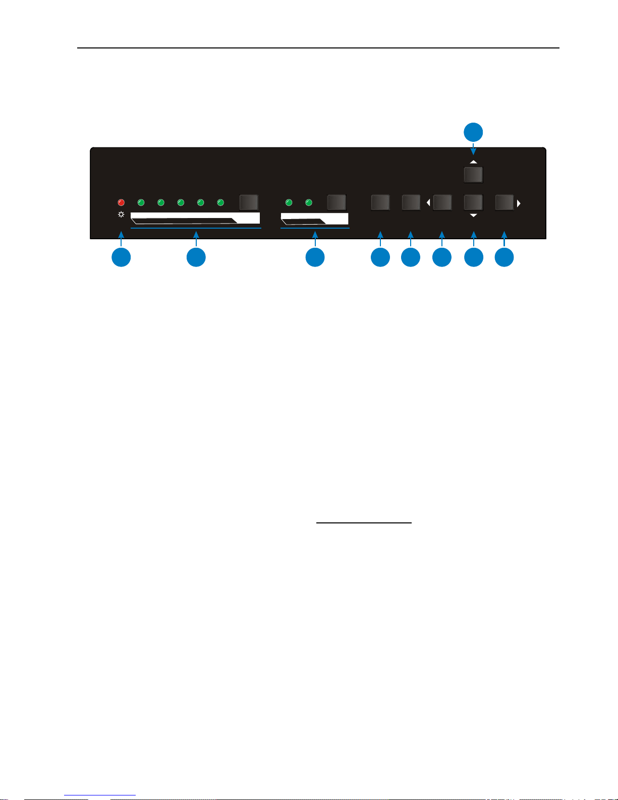
3.1.1 Front Panel
① POWER LED: The LED illuminates red when power is applied, or orange when the
auto-switching mode is chosen.
② INPUT LED & SOURCE SELECTOR:
1-HDMI: The LED illuminates green when 1-HDMI input signal is chosen.
2-HDMI: The LED illuminates green when 2-HDMI input signal is chosen.
3-DP: The LED illuminates green when 3-DP input signal is chosen.
4-VGA: The LED illuminates green when 4-VGA input signal is chosen.
RX HDMI: The LED illuminates green when the HDMI input signal on Receiver is
chosen.
SOURCE SELECTOR: Press this button to select input source signal, or
long-press for 3 seconds or more to enable auto-switching mode.
For more details, please refer to the 5 Button Control.
③ DISPLAY CONTROL: Press this button to turn on/off the displays, and then the
activity LED ON/OFF will illuminates green.
④ RETURN: Return key for OSD.
⑤ MENU/ENTER: Menu or Enter key for OSD.
⑥ VOL-/MUTE: Press this button to turn down the audio output volume, or long-press
3 seconds or more to mute / Left key for OSD.
⑦ RELAY 1: Press this button to raise projector screen. / Up key for OSD.
⑧ RELAY 2: Press this button to lower projector screen. / Down key for OSD.
⑨ VOL+: Press this button to turn up the audio output volume. / Right key for OSD.
RX HDMI SOURCE
AUTO/3s
1-HDMI 2-HDMI 4-VGA3-DP
OFF DISPLAYON
MENU
ENTER
RETURN
RELAY 1
VOL +
VOL -
MUTE/3s
RELAY 2
1
2
3
4
5
6
8
7
9
Page 10
4K Scaler with Soft Codec
6
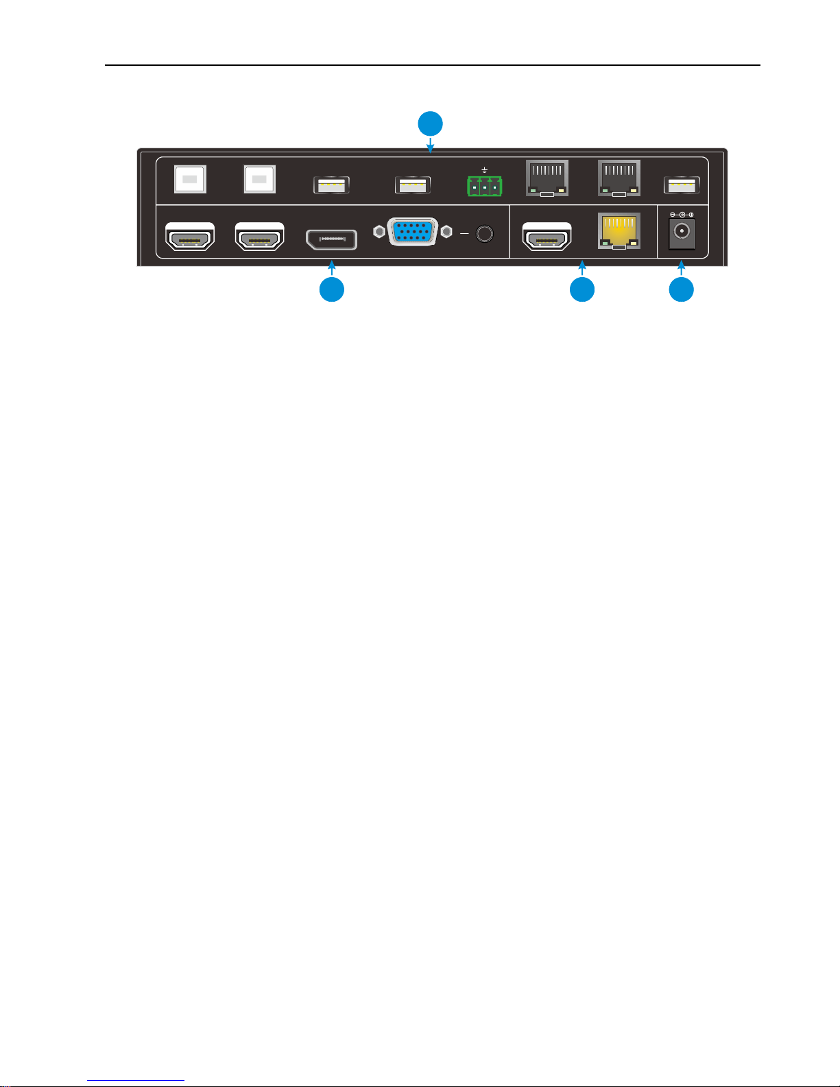
3.1.2 Rear Panel
① INPUT:
VIDEO: 2 HDMI inputs, 1 DP input and 1 VGA input.
AUDIO: 1 VGA auxiliary audio input.
② OUTPUT
HDMI: HDMI video output port.
HDBT: Support PoC. Connect with HDBaseT Receiver to transmit AV signal, IR
or RS232 control signal.
③ CONTROL
PC1&PC2: Two Type-B USB ports, only one can be used to connect with PC,
and the two priority: PC1>PC2.
DEVICE 1& DEVICE 2: Two Type-A USB ports, connect with USB HID devices.
RS232: Serial port, 3-pin phoenix connector, connect with a control device (such
as PC).
TCP/IP: RJ45 connector, connect with PC to control this system via web-based
GUI.
LAN: Ethernet port for extending network signal.
Note: Please notice warning signs. The LAN port can’t be connected with HDBT
port.
FIRMWARE: Type-A USB port for updating system firmware or loading
customized EDID data.
④ DC 24V: DC barrel connector for connecting the included power adapter.
HDMI
DC 24V INPUT
1-HDMI 2-HDMI 3-DP 4-VGA
HDBT
RS232
Tx
Rx
PC 1 DEVICE 1 TCP/IP LAN
OUTPUT
FIRMWARE
CONTROL
PC 2 DEVICE 2
AUDIO
1
2
4
3
Page 11
4K Scaler with Soft Codec
7
3.2 Receiver
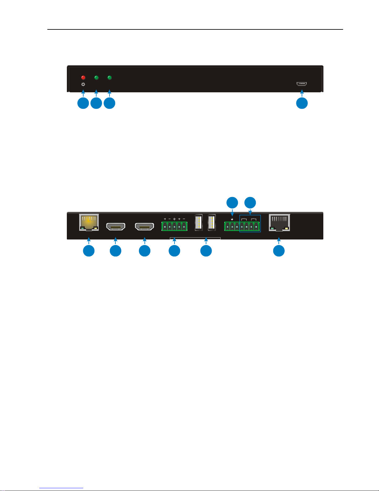
3.2.1 Front Panel
① POWER LED: The LED illuminates red when power is applied.
② HDBT LED: The LED illuminates green when HDBT input signal present.
③ HDMI LED: The LED illuminates green when HDMI input signal present.
④ FIRMWARE: Type-A USB port for updating system firmware.
3.2.2 Rear Panel
① HDBT IN: Connect to the HDBT OUT port on Transmitter via CAT5e/6a/7 cable,
support PoC technology.
② HDMI IN: HDMI input port.
③ HDMI OUT: HDMI output port.
④ AUDIO OUT: Stereo balanced L/R audio output port.
⑤ DEVICES: Two Type-A USB ports, connect with USB HID devices.
⑥ RS232: Serial port, 3-pin phoenix connector, connect with the display device (such
as projector) needed to be control via RS232 commands.
⑦ RELAY1 & RELAY2: Connect with relay device (such as projector screen).
⑧ LAN: Ethernet port, work with the LAN port on Transmitter to extend network signal.
Note: Please notice warning signs. The LAN port can’t be connected with HDBT port.
FIRMWARE
HDBT HDMI
1
2
3
4
HDBT IN
HDMI IN HDMI OUT AUDIO OUT
L R
DEVICES
1
2
Tx Rx
CONTROL
Relay1 Relay2
LAN
1
2
3
4
5
8
6
7
Page 12
4K Scaler with Soft Codec
8
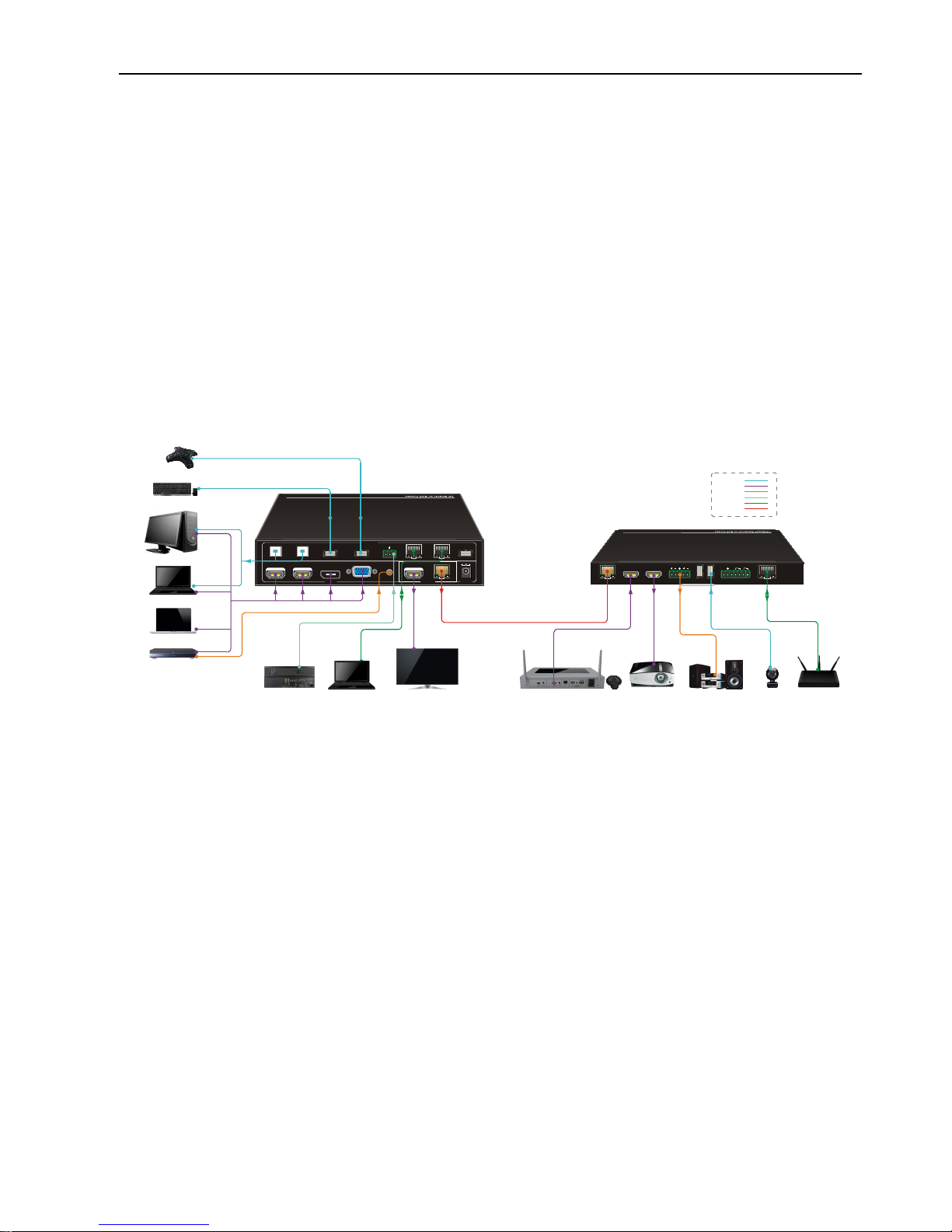
4. System Connection
4.1 Usage Precaution
Verify all components and accessories included before installation.
System should be installed in a clean environment with proper temperature and
humidity.
All of the power switches, plugs, sockets and power cords should be insulated and
safe.
All devices should be connected before power on.
4.2 System Diagram
DC 12V
HDMI
DC 24V INPUT
1-HDMI 2-HDMI 3-DP 4-VGA
HDBT
RS232
Tx
Rx
PC 1 DEVICE 1 TCP/IP LAN
OUTPUT
FIRMWARE
CONTROL
PC 2 DEVICE 2
AUDIO
DVD
MacBo ok
Lapto p
PC
DEVICES
Tx Rx
CONTROLHDBT IN
HDMI IN H DMI OUT L+R OUT
Relay1 Relay2
LAN
1 2
USB Mic ropho ne
Wirel ess Key board a nd Mouse
Centr al Cont rol Sys tem
Route r
Proje ctor
Wirel ess BYO DTV Speak er
USB Cam era
Video :
Audio :
RS232 :
HDBas eT:
Ether net:
USB:
Lapto p
Page 13
4K Scaler with Soft Codec
9
5. Button Control
Front panel buttons can be used for signal switching, OSD, volume adjusting.
5.1 Manual Switching
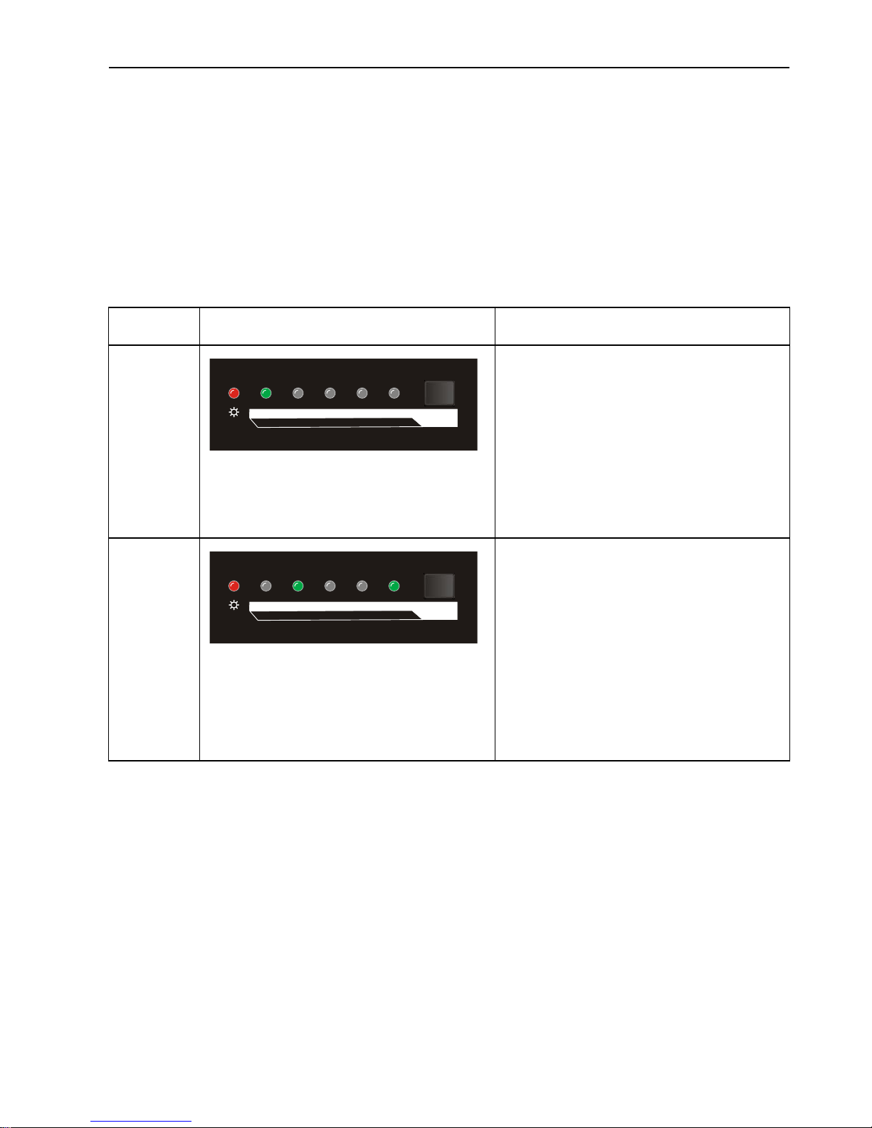
Press the SOURCE/AUTO button to select one input source for Transmitter, press again
to select next source, switching sequentially between 1-HDMI, 2-HDMI, 3-DP and
4-VGA. The corresponding LED illuminates green.
The Receiver also features one HDMI input port, if you need to output the source signal
via its HDMI output port. The following is an example.
LED Status
Description
Status 1
The 1-HDMI LED illuminates green,
other source LEDs are gone.
The 1-HDMI is selected as input
source. The input signal will be
transmitted to all video output ports
of Transmitter and Receiver.
Status 2
The 2-HDMI and RX HDMI LEDs
illuminate green, other source LEDs
are gone.
The 2-HDMI is selected as input
source for Transmitter. The input
signal will be transmitted to all
video output ports of Transmitter.
The HDMI input signal on
Receiver will be only transmitted
to the HDMI output port of
Receiver.
Follow the below steps to switch to the status 2 from status 1.
① Press the SOURCE/AUTO button once to select 2-HDMI, and then release this
button.
② Press the SOURCE/AUTO button continuously until the RX HDMI LED illuminates
green to select the HDMI input for Receiver.
RX HDMI SOURCE
AUTO/3s
1-HDMI 2-HDMI 4-VGA3-DP
RX HDMI SOURCE
AUTO/3s
1-HDMI 2-HDMI 4-VGA3-DP
Page 14

4K Scaler with Soft Codec
10
5.2 Auto Switching
Long-press SOURCE/AUTO button for 3 seconds or more to enable auto-switching
mode, and the auto-switching mode abides by the following principles:
New input
Once detecting a new input signal, the Transmitter would switch to this new signal
automatically.
Once connecting a source device to the HDMI IN port of Receiver, the Receiver will
switch to this source to output HDMI signal via HDMI OUT port automatically.
Rebooting device
The Transmitter have the ability to save the last configuration before losing power. If
the last switching mode is auto-switching, once rebooted, the Transmitter will
automatically enter auto-switching mode, then detect all inputs and memorize their
connection status for future rebooting using. If the last displayed signal is still
available, the unit will output the signal. If not, the unit will detect all the input signals
with priority from 1-HDMI to 4-VGA. When detected the first signal, it will transfer to
output.
Signal removing
Once removing the current display signal, the Transmitter will detect all input signals
with priority from 1-HDMI to 4-VGA. It will transfer the signal firstly detected to be
available to output devices.
Note:
Auto-switching function works only when inputting new signal, removing a signal or
power rebooting.
The HDMI input source on Receive cannot be selected under auto-switching mode.
5.3 Volume Adjustment
The Receiver features audio output ports for connecting speaker or AV amplifier.
Press the VOL+ or VOL- button on Transmitter to turn up or turn down the volume.
Meantime, it sends CEC commands to the display to turn up or down the display
volume.
Page 15
4K Scaler with Soft Codec
11
6. RS232 Control
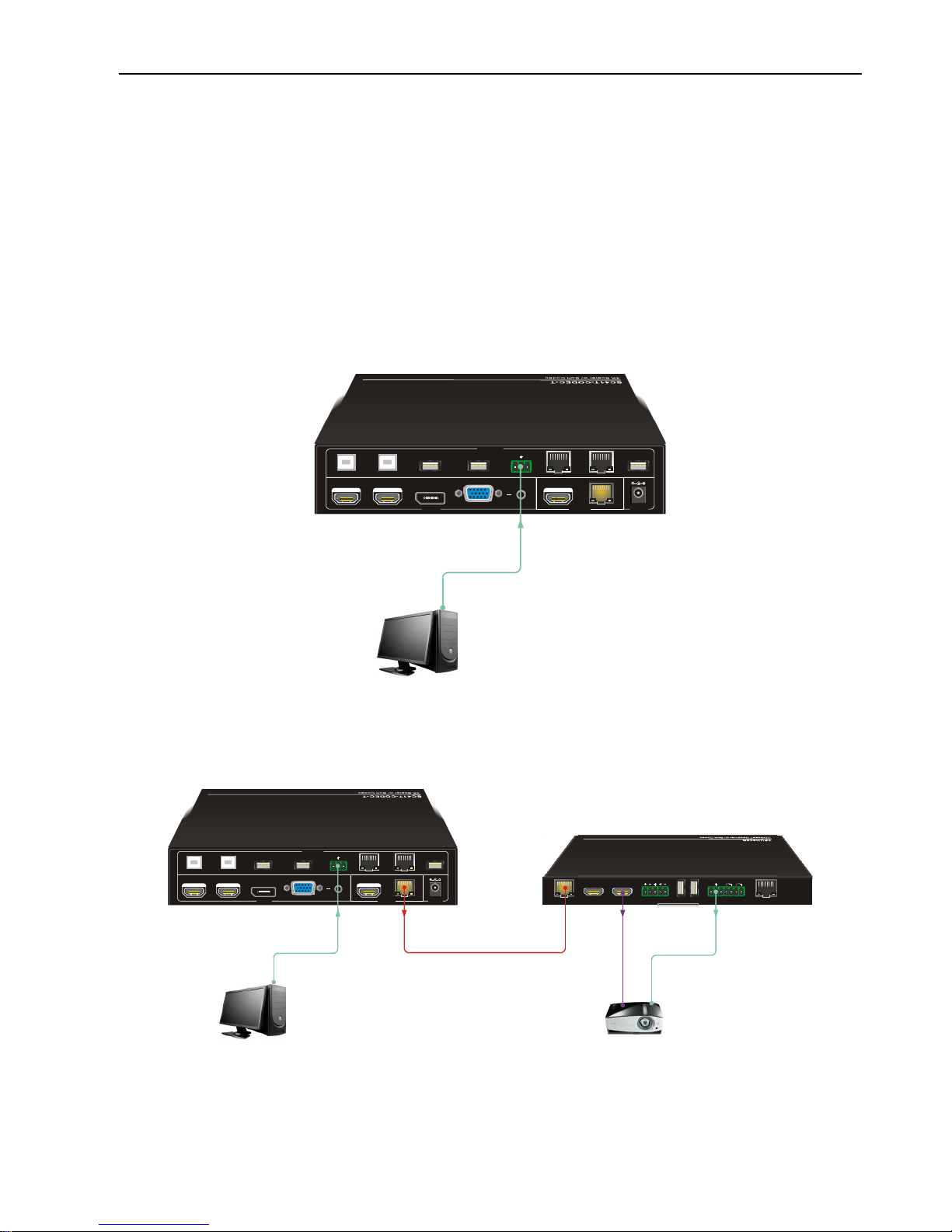
As RS232 commands can be transmitted to Receiver from the Transmitter, so it is able
to control the Transmitter or the third-party device (such as projector) on Receiver from
local.
The baud rate support 2400, 4800, 9600(default), 19200, 38400, 57600 or 115200.
6.1 RS232 Connection
There are two RS232 control modes.
Control Transmitter
Control Display
HDMI
DC 24V INPUT
1-HDMI 2-HDMI 3-DP 4-VGA
HDBT
RS232
Tx
Rx
PC 1 DEVICE 1 TCP/IP LAN
OUTPU T
FIRMWAR E
CONTR OL
PC 2 DEVICE 2
AUDIO
PC
HDMI
DC 24V INPUT
1-HDMI 2-HDMI 3-DP 4-VGA
HDBT
RS232
Tx
Rx
PC 1 DEVICE 1 TCP/IP LAN
OUTPUT
FIRMWARE
CONTROL
PC 2 DEVICE 2
AUDIO
DC 12V
PC
DEVICES
Tx Rx
CONTROLHDBT IN
HDMI IN HD MI OUT L+R OUT
Relay1 Re lay2
LAN
1 2
Proj ector
Page 16
4K Scaler with Soft Codec
12
6.2 RS232 Control Software
Installation/uninstallation
Installation Copy the control software file to the computer connected with the
Transmitter.
Uninstallation Delete all the control software files in corresponding file path.
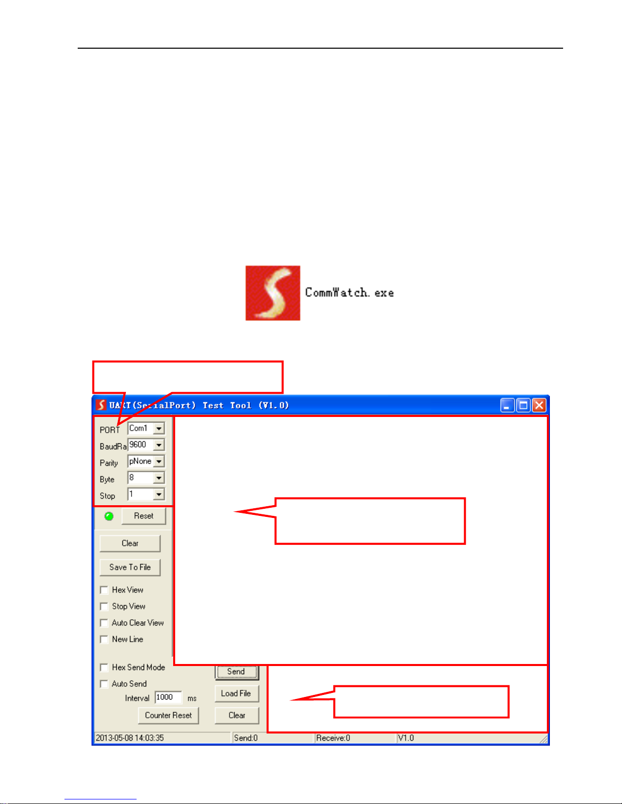
Basic Settings
First to connect the Transmitter with all input devices and output devices needed, then
to connect it with a PC which is installed with RS232 control software. Double-click the
software icon to run this software. Here we take the software CommWatch.exe as
example. The icon is showed as below:
The interface of the control software is showed as below:
Parameter Configuration area
Monitoring area, indicates if the
command sent works.
Command Sending area
Page 17

4K Scaler with Soft Codec
13
Please set the parameters of COM number, bound rate, data bit, stop bit and the parity
bit correctly, and then you are able to send command in Command Sending Area.
6.3 RS232 Command
Communication protocol: RS232 Communication Protocol
Baud rate: 9600 Data bit: 8 Stop bit: 1 Parity bit: none
The end mark of command is “<CR><LF>”.
6.3.1 Source Switching
Command
Function
Feedback
SWIN H1
Switch to 1-HDMI input.
Switch to HDMI1
SWIN H2
Switch to 2-HDMI input.
Switch to HDMI2
SWIN DP
Switch to 3-DP input.
Switch to DP
SWIN VG
Switch to 4-VGA input.
Switch to VGA
SWIN
RXHDMI
Switch to RX HDMI input.
Switch to RX HDMI
AUTO 01
Enable auto-switching.
Auto Switching
AUTO 00
Enable manual-switching.
Manual Switching
?GET IN
Get the input source of Transmitter.
(HDMI1,HDMI2,DP,VGA)
TX Device Input: HDMI1
Get the input source of Receiver.
(HDMI,HDBT)
RX Device Input: HDMI
?GET AUTO
Get the switching mode.
Manual Switching/Auto
Switching
VGAA
Auto-adjust the input parameter (VGA
only).
VGA Input Auto
6.3.2 Audio Adjustment
Command
Function
Feedback
AUMT S1
Mute source audio.
Audio Mute Source:
Enable
AUMT S0
Unmute source audio.
Audio Mute Source:
Disable
Page 18

4K Scaler with Soft Codec
14
Command
Function
Feedback
AUMT V1
Mute VGA auxiliary input audio.
Audio Mute VGA: Enable
AUMT V0
Unmute VGA auxiliary input audio.
Audio Mute VGA: Disable
?GET AUMT
Get the Source mute status.
Audio Mute Source:
Enable
Get the VGA auxiliary audio mute status.
Audio Mute VGA: Enable
VOLS AP
Turn up the source audio volume
(xx=00~60).
Source Volume: xx
VOLS AN
Turn down the source audio volume
(xx=00~60).
Source Volume: xx
VOLV AP
Turn up the VGA auxiliary audio volume
(xx=00~60).
VGA Volume: xx
VOLV AN
Turn down the VGA auxiliary audio
volume (xx=00~60).
VGA Volume: xx
VOLS xx
Set the source audio volume (xx=00~60).
Source Volume: xx
VOLV xx
Set the VGA auxiliary audio volume
(xx=00~60).
VGA Volume: xx
?GET VOL
Get the source audio volume (xx=00~60).
Source Volume: xx
Get the VGA auxiliary audio volume
(xx=00~60).
VGA Volume: xx
6.3.3 Output Resolution
The default output resolution is 3840x2160@30Hz. Below is a list of the output
resolutions the built-in scaler can output.
Command
Function
Feedback
TRES 01
Set the output resolution for Transmitter
to 3840x2160@30Hz.
TX Device Resolution:
3840x2160
TRES 02
Set the output resolution for Transmitter
to 1920X1080.
TX Device Resolution:
1920x1080
TRES 03
Set the output resolution for Transmitter
to 1280x720.
TX Device Resolution:
1280x720
RRES 01
Set the output resolution for Receiver to
3840x2160@30Hz.
RX Device Resolution:
3840x2160
RRES 02
Set the output resolution for Receiver to
RX Device Resolution:
Page 19

4K Scaler with Soft Codec
15
Command
Function
Feedback
1920x1080.
1920x1080
RRES 03
Set the output resolution for Receiver to
1280x720.
RX Device Resolution:
1280x720
?GET RES
Get the output resolution for
Transmitter.
Tx Device Resolution:
1920x1080
Get the output resolution for Receiver.
Tx Device Resolution:
1920x1080
6.3.4 Auto Power-off Setup
Command
Function
Feedback
?GET TIME
Check the auto power-off mode.
Auto Switch Mode no
input to shutdown time:
Disable
Manual Switch Mode no
input to shutdown time:
Disable
TIME AD
Auto Switch Mode: Disable the auto
power-off function.
Auto Switch Mode no
input to shutdown time:
Disable
TIME A1
Auto Switch Mode: Set the auto power-off
time to 1 minute when No signal input.
Auto Switch Mode no
input to shutdown time: 1
minutes
TIME A2
Auto Switch Mode: Set the auto power-off
time to 2 minute when No signal input.
Auto Switch Mode no
input to shutdown time: 2
minutes
TIME A3
Auto Switch Mode: Set the auto power-off
time to 5 minute when No signal input.
Auto Switch Mode no
input to shutdown time: 5
minutes
TIME A4
Auto Switch Mode: Set the auto power-off
time to 10 minute when No signal input.
Auto Switch Mode no
input to shutdown time:
10 minutes
TIME MD
Manual Switch Mode: Disable auto
power-off time function.
Manual Switch Mode no
input to shutdown time:
Disable
Page 20

4K Scaler with Soft Codec
16
Command
Function
Feedback
TIME M1
Manual Switch Mode: Set the power-off
time to 1 minute.
Manual Switch Mode no
input to shutdown time: 1
minutes
TIME M2
Manual Switch Mode: Set the power-off
time to 2 minute.
Manual Switch Mode no
input to shutdown time: 2
minutes
TIME M3
Manual Switch Mode: Set the power-off
time to 5 minute.
Manual Switch Mode no
input to shutdown time: 5
minutes
TIME M4
Manual Switch Mode: Set the power-off
time to 10 minute.
Manual Switch Mode no
input to shutdown time:
10 minutes
6.3.5 CEC Command
Command
Function
Feedback
CECS P0
Turn off the source device by using CEC
way.
CEC: Turn Source off
CECS P1
Turn on the source device by using CEC
way.
CEC: Turn Source on
CECD P0
Turn off the display device by using CEC
way.
CEC: Turn Display off
CECD P1
Turn on the display device by using CEC
way.
CEC: Turn Display on
Page 21

4K Scaler with Soft Codec
17
6.3.6 Relay Control
Command
Function
Feedback
RLY1 ON
Turn on the Relay 1.
Relay 1 on
RLY1 OFF
Turn off the Relay 1.
Relay 1 off
RLY2 ON
Turn on the Relay 2.
Relay 2 on
RLY2 OFF
Turn off the Relay 2.
Relay 2 off
6.3.7 EDID Configuration
Command
Function
Feedback
EDID DF
The source device obtains the default
EDID 3840x2160@30Hz.
EDID: Initial
EDID US
Load customize EDID data from U-disk.
EDID: User
?GET EDID
Get EDID status.
EDID: Initial/ User
6.3.8 HDCP Compliance
Command
Function
Feedback
HDCP 01
HDCP pass-through mode.
HDCP: ON
HDCP 00
Disable HDCP.
HDCP: OFF
?GET HDCP
Get HDCP status.
HDCP: ON /OFF
6.3.9 Device Setup
Command
Function
Feedback
SFUD TX
Update the software of Transmitter.
TX Device Software
Update
SFUD RX
Update the software of Receiver.
RX Device Software
Update
?GET REV
Get the system version.
Vx.x.x
FRST
Restore to factory defaults.
Factor Reset
WAKE
Wake up the system.
Wake Up
STBY
Let this system enter in standby mode.
Go To Standby
?GET IP
Get the IP address.
192.168.0.178!
Page 22
4K Scaler with Soft Codec
18
7. OSD Control
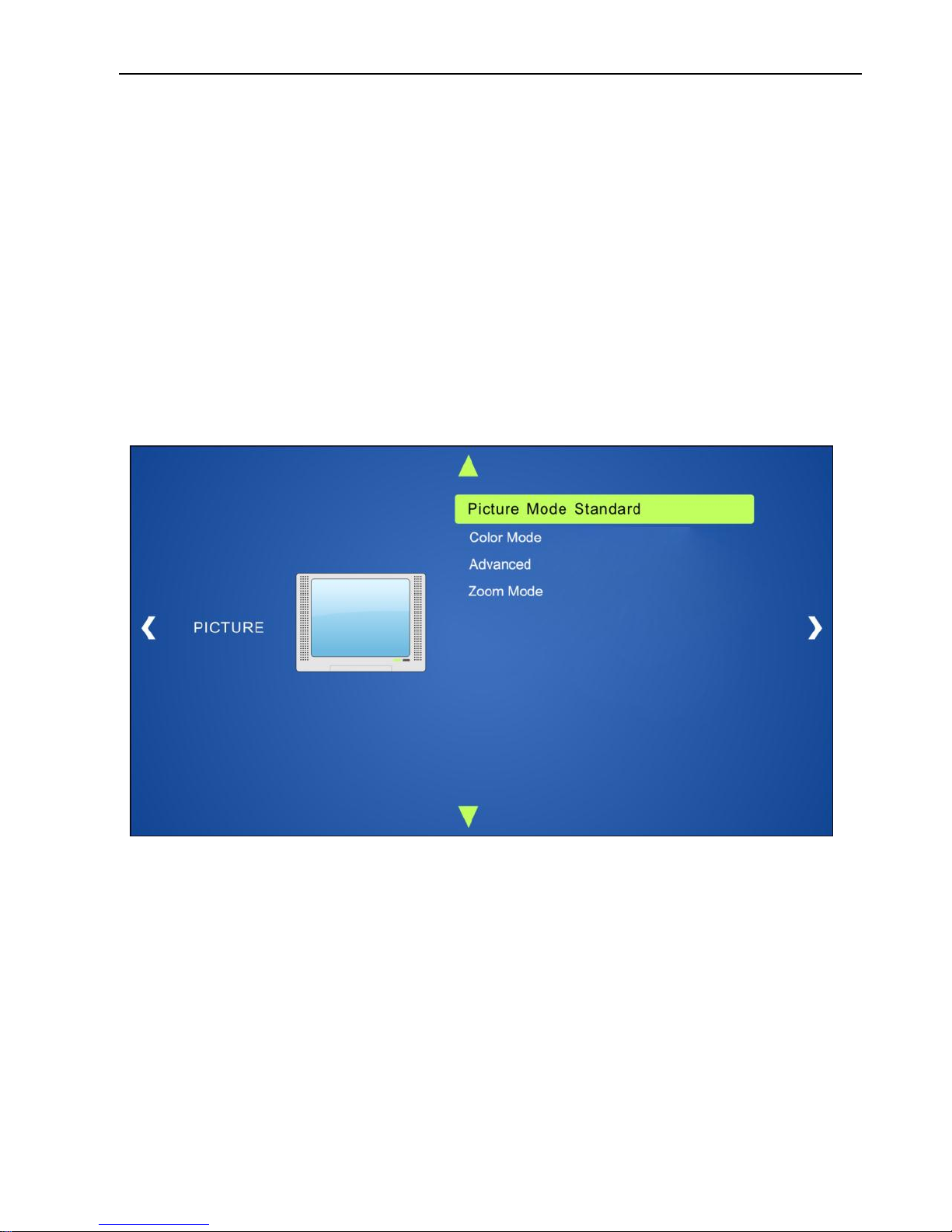
The system provides a powerful OSD operation menu, including picture settings and
system setup.
Operation:
Press the button MENU/ENTER to enter OSD menu.
Press direction buttons (Left/Right/Up/ down) to select function on OSD menu.
Press MENU/ENTER button to confirm the selected function.
7.1 Picture
Including Picture Mode, Color Mode, Advanced and Zoom Mode.
Picture mode: Including Dynamic, Standard, Mild, and User. Only in User mode,
will it be able to set the image contrast, brightness, color and sharpness.
Color Mode: Including Cool, Medium, Warm and User. And only in User mode, it is
able to set values for Red, Green and Blue (RGB).
Advanced: Including H-Pos, V-Pos, Clock, Phase, and Auto.
Zoom Mode: Including Normal, Zoom, Cinema, Wide, Point to Point.
Page 23
4K Scaler with Soft Codec
19
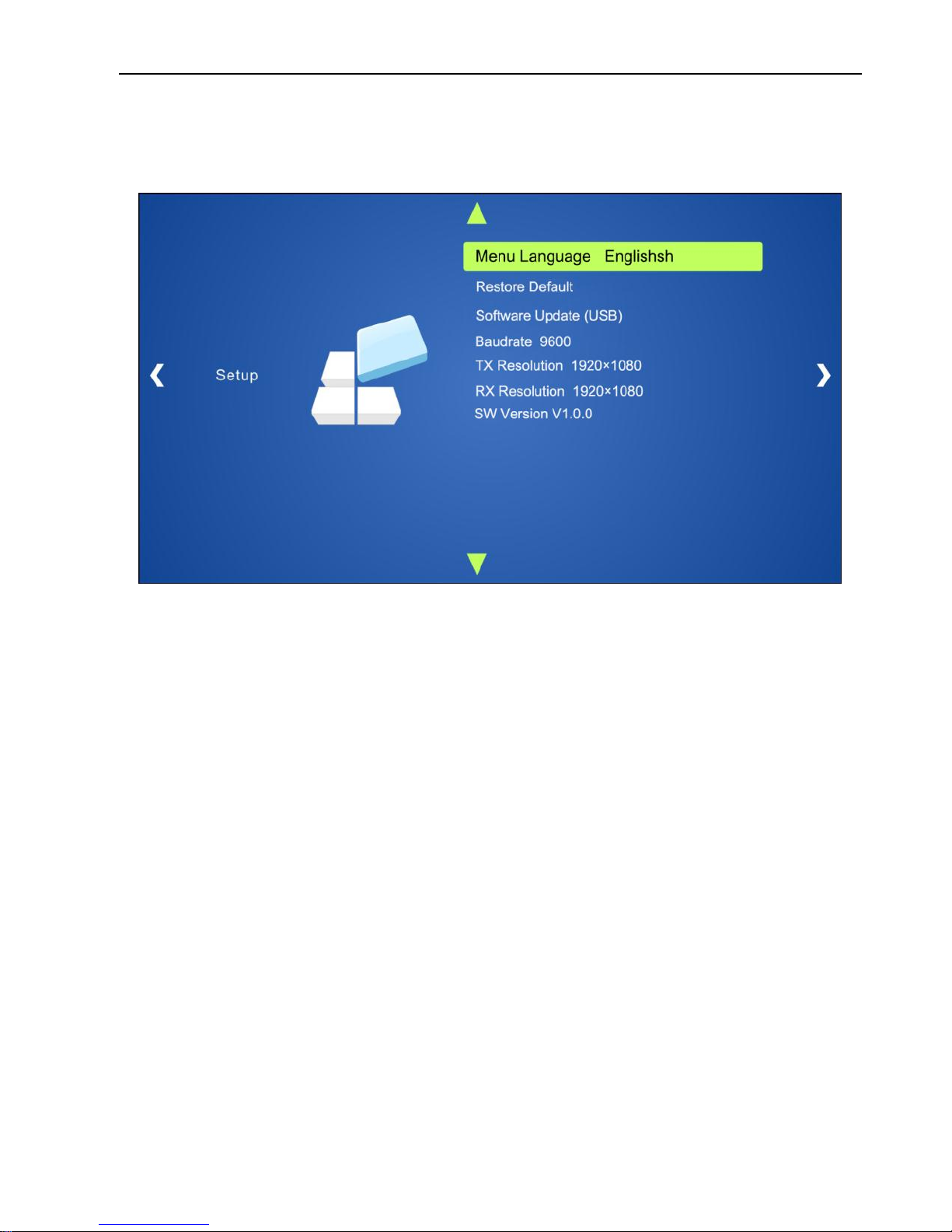
7.2 Setup
Including Menu Language, Restore Default, Software Update, Baudrate, TX Resolution,
RX Resolution and SW Version.
Menu Language: Supports 7 languages, including English (default), Chinese etc.
Restore Default: Restores to original system state.
Software Update (USB): Insert the USB flash disk with updating file to the
FIRMWARE port of the Scaler Switcher, to update the software through this menu.
Baudrate: Set the baud rate for RS232 control, and it support 2400、4800、9600、
19200、38400、57600、115200.
TX Resolution: Set the output resolutions for Transmitter, and it support
3840x2160@30Hz, 1920x1080, 1280x720.
TX Resolution: Set the output resolutions for Receiver, and it support
3840x2160@30Hz, 1920x1080, 1280x720.
SW Version: Software version.
Page 24
4K Scaler with Soft Codec
20
8. GUI Control
In addition to control the system via front panel button and RS232 control software. The
system can be controlled via web-based GUI. It allows users to interact with the system
through graphical icons and visual indicators.
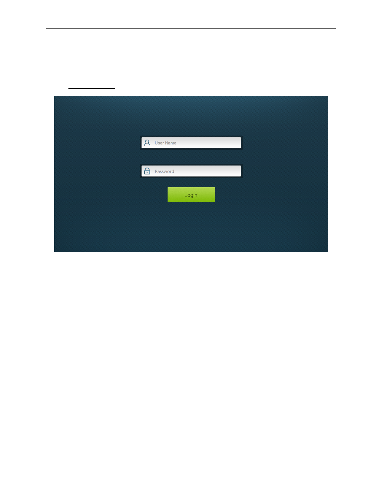
Type 192.168.0.178 in your browser, it will enter the log-in interface shown as below:
This system divides into administrator and user mode.
Administrator mode: User name: admin; Password: admin (default setting)
User mode: User name: user; Password: user (default setting)
Note: Log in as admin can access more configuration interfaces than user. Here is a
brief introduction to the interfaces.
Page 25
4K Scaler with Soft Codec
21
8.1 Control Menu
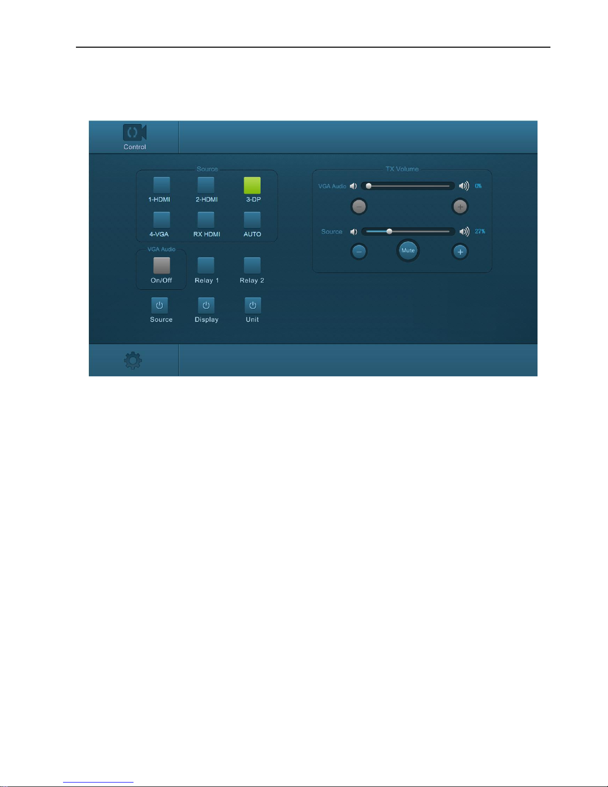
Type the default user name and password, and then click Login to enter the control
menu shown as below:
Sources:
Click the corresponding button (1-HDMI, 2-HDMI, 3-DP, 4-VGA and RX HDMI)
to select video input source.
Click AUTO button to enter auto-switching mode.
VGA Audio: Click this button to turn on/off the VGA auxiliary audio input.
Relay1: Click this button to raise projector screen.
Relay2: Click this button to lower projector screen.
Source: Click this button to turn on/off source device.
Display: Click this button to turn on/off output display device.
Unit: Click this button to turn on/off the Transmitter and Receiver.
TX Volume: Click +/- button or drag the volume bar to adjust volume.
Page 26
4K Scaler with Soft Codec
22
8.2 Configuration Menu
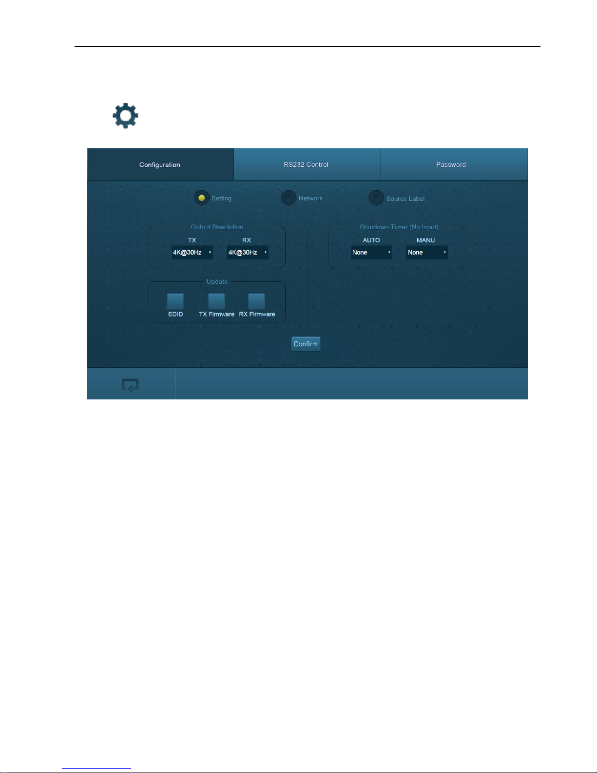
① Setting
Click on control menu to enter configuration menu shown as below:
Output Resolution: Select the output resolution for Transmitter or Receiver.
Update:
EDID: Insert the USB flash disk with EDID file to the FIRMWARE port of
Transmitter, and then click EDID button to start update procedure.
TX Firmware: Insert the USB flash disk with software updating file to the
FIRMWARE port of Transmitter, and then click TX Firmware button to start
update procedure.
RX Firmware: Insert the USB flash disk with software updating file to the
FIRMWARE port of Receiver, and then click RX Firmware button to start update
procedure.
Shutdown Time (NO Input): Set the auto power-off time or manual power-off time,
including none, 1 minute, 2minutes, 5minutes and 10 Minutes. If the system can’t
detect video source input, it will automatically shut down after a preset interval.
Page 27
4K Scaler with Soft Codec
23
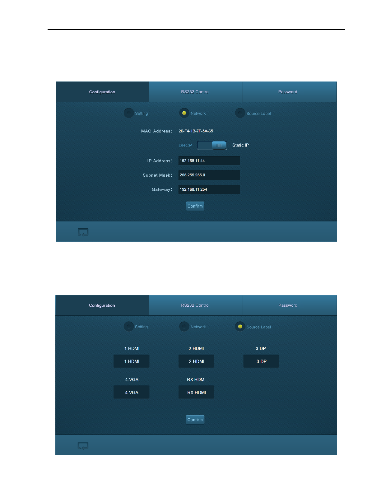
② Network
Click Network to enter the below menu to select the dynamic or static mode. Under
static mode, then IP address, subnet mask and gateway can be reset.
③ Source
Click Source Label to enter the below menu to rename the input selection buttons.
Page 28
4K Scaler with Soft Codec
24
8.3 RS232 Control Menu
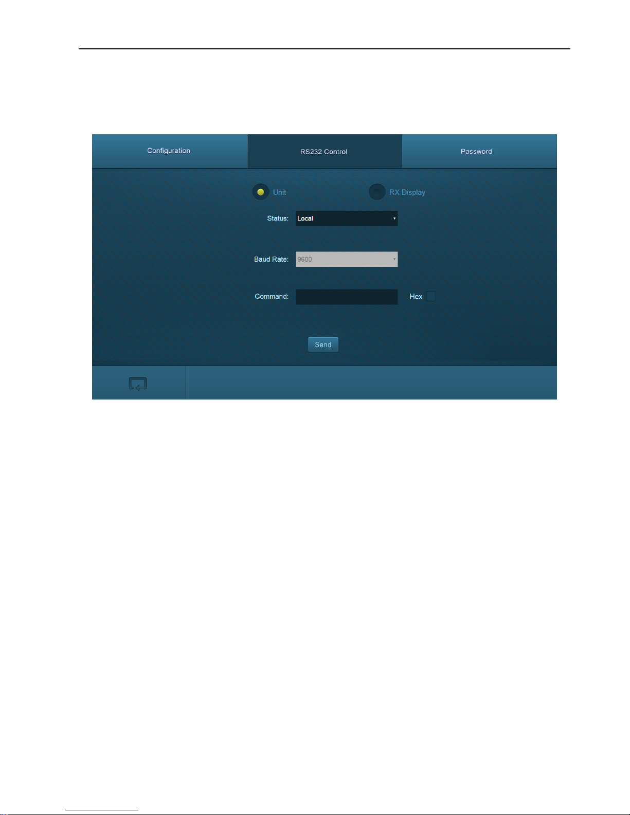
① Click RS232 Control on the top of interface to enter the below menu to send
commands to control far-end third-party device.
Status:
Local: Refers to the RS232 port of the Transmitter.
HDBT: Refers to the RS232 port of the Receiver.
Baud Rate: The baud rate of local port is 9600, but for HDBT port, it support 2400、
4800、9600、19200、38400、57600、115200.
Command: Typing commands in this box to control the third-party device (such as
integrated control system) connected to Transmitter, or the far-end third-party device
(such as projector) connected to Receiver. If check the “Hex”, you can type RS232
commands with hexadecimal value in the box.
Page 29
4K Scaler with Soft Codec
25
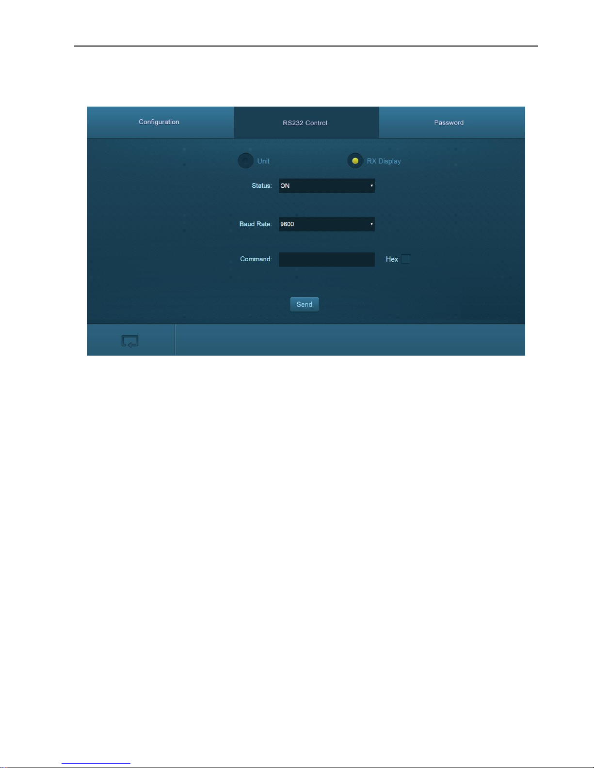
② Click RX DISPLAY to enter the below menu to set the ON/OFF button function to
turn on/ off the display device (such as projector).
Status: ON or OFF can be chosen.
Baud Rate: Supports 2400、4800、9600、19200、38400、57600、115200.
Command: Typing the control command of display device, and then click Send, the
command will be sent to DISPLAY ON/OFF button.
Page 30
4K Scaler with Soft Codec
26
8.4 Password Menu
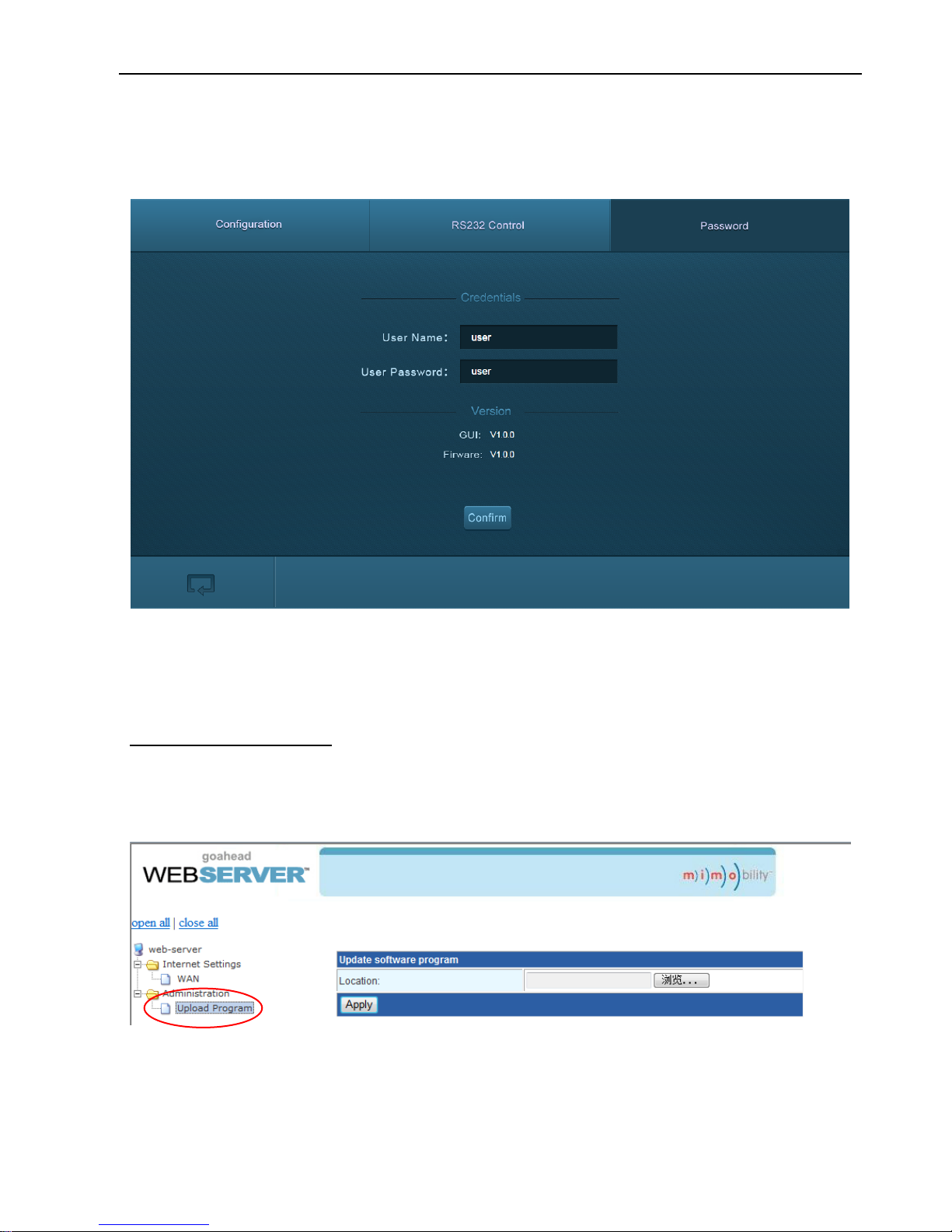
Click Password on the top of interface to enter the below menu to reset the username
and password.
8.5 GUI Update
Web-based GUI for the Scaler Switcher supports online update in
http://192.168.0.178:100. Type the username and password (the same as the GUI log-in
settings, modified password will be available only after rebooting) to log in the
configuration interface. After that, click Administration at the source menu to get to
Upload Program as shown below:
Select the desired update file and press Apply, it will start upgrading then.
Page 31
4K Scaler with Soft Codec
27
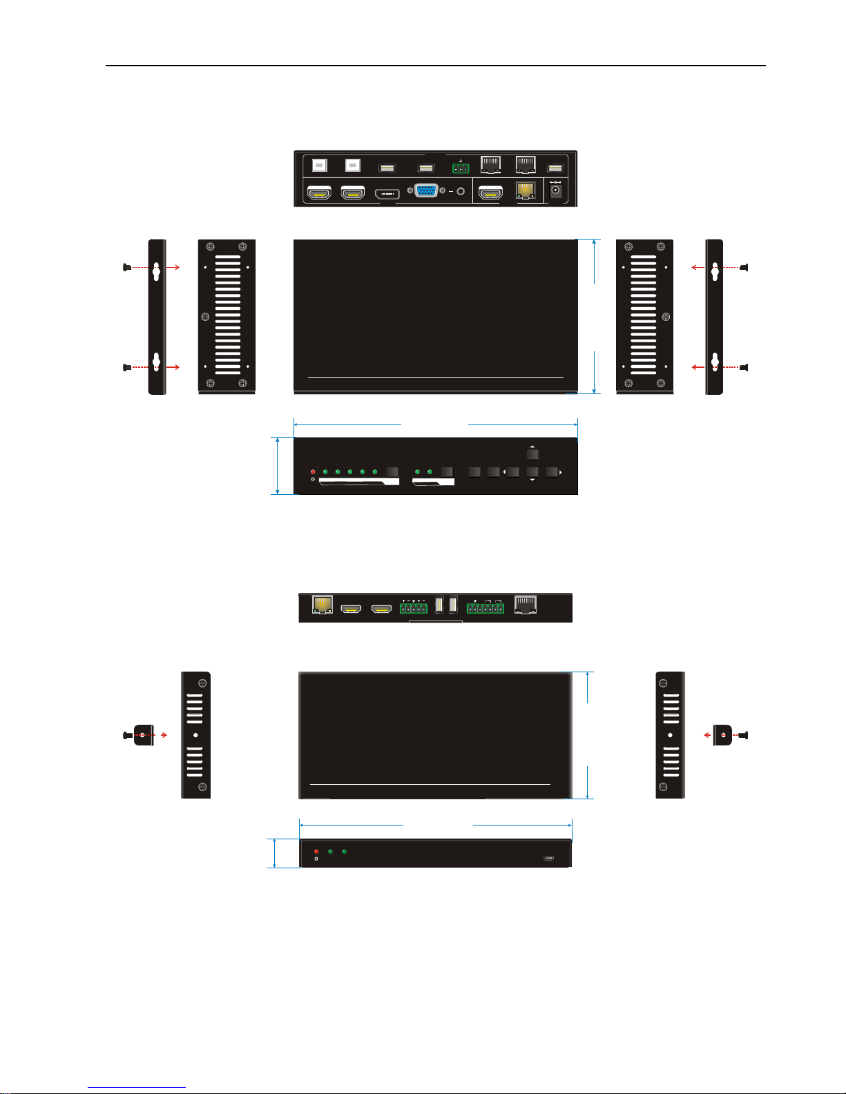
9. Panel Drawing
9-1 Transmitter
9-2 Receiver
HDMI
DC 24V INPUT
1-HDMI 2-HDMI 3-DP 4-VG A
HDBT
RS232
Tx
Rx
PC 1 DEVI CE 1 TCP/IP LAN
OUTPUT
FIRMWARE
CONTRO L
PC 2 DEVICE 2
AUDIO
4K Scaler w/ Soft Codec
RX HDMI SO URCE
AUTO/3s
1-HDMI 2 -HDMI 4-VGA3-DP
OFF DISPLAYON
MENU
ENTER
RETURN
RELAY 1
VOL +
VOL -
MUTE/3s
RELAY 2
220.0 mm
4
4
.0
m
m
1
2
0
.0 m
m
HDBaseT Receiver w/ Soft Codec
FIRMWA RE
HDBT HDM I
HDBT IN
HDMI IN HDM I OUT AUDIO OU T
L R
DEVICE S
1
2
Tx Rx
CONTRO L
Relay1 Relay2
LAN
205.0 mm
2
1
.5
m
m
9
5
.0
m
m
Page 32

4K Scaler with Soft Codec
28
10. Troubleshooting & Maintenance
Problems
Potential Causes
Solutions
Output image with
snowflake
Bad quality of the connecting
cable
Try another high quality
cable.
Fail or loose connection
Make sure the
connection is good
No output image when
switching
No signal at the input / output
end
Check with oscilloscope
or multimeter if there is
any signal at the input/
output end.
Fail or loose connection
Make sure the
connection is good
The switcher is broken
Send it to authorized
dealer for repairing.
POWER indicator
doesn’t work or no
respond to any operation
Fail connection of power cord.
Make sure the power
cord connection is
good.
Cannot control the
device by control device
(e.g. a PC) through
RS232 port
Wrong RS232 communication
parameters
Type in correct RS232
communication
parameters.
Broken RS232 port
Send it to authorized
dealer for checking.
If your problem persists after following the above troubleshooting steps, seek further
help from authorized dealer or our technical support.
Page 33

4K Scaler with Soft Codec
29
11. Customer Service
The return of a product to our Customer Service implies the full agreement of the terms
and conditions hereinafter. There terms and conditions may be changed without prior
notice.
① Warranty
The limited warranty period of the product is fixed 3 (three) years. The warranty
period runs from the date purchase indicated on the invoice.
② Scope
These terms and conditions of Customer Service apply to the customer service
provided for the products or any other items sold by authorized distributor only.
③ Warranty Exclusions:
Warranty expiration.
Factory applied serial number has been altered or removed from the product.
Damage, deterioration or malfunction caused by:
Normal wear and tear.
Use of supplies or parts not meeting our specifications
No certificate or invoice as the proof of warranty.
The product model showed on the warranty card does not match with the
model of the product for repairing or had been altered.
Damage caused by force majeure.
Servicing not authorized by distributor.
Any other causes which does not relate to a product defect.
Shipping fees, installation or labor charges for installation or setup of the product.
④ Documentation:
Customer Service will accept defective product(s) in the scope of warranty coverage
at the sole condition that the defeat has been clearly defined, and upon reception of
the documents or copy of invoice, indicating the date of purchase, the type of
product, the serial number, and the name of distributor.
Remarks: For further assistance or solutions, please contact your local distributor.
 Loading...