

Page 1
MedizinTechnik
English
Mounting Instructions
ATMOS Cam
ATMOS Strobo LED
in ATMOS S 61 Servant vision
2012-08 Index: 01
Mounting Instructions
ATMOS MedizinTechnik
GmbH & Co. KG
Ludwig-Kegel-Straße 16
79853 Lenzkirch/Germany
Tel. +49 7653 689-222
Fax +49 7653 689-292
M531.2010.B
M531.2020.B
M531.2055.B
M531.2065.B
M531.2070.B
M531.2080.B
M531.2090.B
M531.2050.B
service@atmosmed.de
www.atmosmed.de
Page 2

1.0 General Notes
These assembly instructions explain the retrofi tting of the options in the ATMOS S 61 Servant vision from construction year
07/2009:
531.2010.0 ATMOS Cam without image storage (retrofi t kit 531.2010.N)
531.2020.0 ATMOS Cam 21 DV (retrofi t kit 531.2020.N)
531.2080.0 ATMOS Cam 21 DV DATA (retrofi t kit 531.2080.N)
531.2065.0 ATMOS Cam 31 (retrofi t kit 531.2065.N)
531.2055.0 ATMOS Cam 31 DATA (retrofi t kit 531.2055.N)
531.2070.0 ATMOS Cam 31 DV (retrofi t kit 531.2070.N)
531.2090.0 ATMOS Cam 31 DV DATA (retrofi t kit 531.2050.N)
531.2050.0 ATMOS Strobo 21 LED (retrofi t kit 531.2050.N)
On the older versions of the ATMOS S 61 Servant vision the rear lead frame on the camera side may need to
be adjusted.
1.1 Gültige Gebrauchsanweisung
The valid operating instructions for the ATMOS S 61
Servant (REF 53x.xxxx.B) are constituent part of these
service instructions. Precise observation of the instructions
regarding fi rst-time operation, handling and maintenance
is a precondition for carrying out service work.
1.2 Information on manufacturer
Further information, accessories and spare parts
are available from:
ATMOS
Medizintechnik GmbH & Co. KG
Ludwig-Kegel-Str. 16
79853 Lenzkirch
Germany
Phone: + 49 7653 689-222
1.3 Exclusion of liability
No warranty claims will be accepted for any damage caused
by the use of non-original accessories and consumables.
ATMOS only assumes responsibility for the unit, as far
as safety, dependability and functionality are concerned,
if assembly, readjustment, modifi cations, extensions or
repairs are carried out by ATMOS or by persons authorized
by ATMOS.
The user‘s safety and the trouble-free operation of the device are only guaranteed if original ATMOS components are
used.
In the case that non-original accessories and consumables
are use, ATMOS cannot guarantee safe operation and safe
function of the components from the ATMOS S 61 Servant.
Fax:
+ 49 7653 689-392 (Vertrieb Inland /
Domestic Sales)
+ 49 7653 689-391 (Vertrieb Ausland /
Export Sales)
+ 49 7653 689-292 (Kundenservice /
Client Service)
E-Mail: service@atmosmed.de
Internet: http://www.atmosmed.de
Reproduction and distribution of these instructions
– even in part – only with the written consent from
ATMOS
Medizintechnik GmbH & Co. KG.
2
Particularly important notes
Page 3
1.0 General Notes
1.4 For your safety
The ATMOS S 61 Servant ENT workstation is produced
•
according to IEC 601/ EN 60601 and listed in the
following classes:
• VDE Class of protection 1
• Class IIa (EEC 93/42).
• The device may only be connected to a properly installed
shockproof socket. Correct confi guration for installation
to country-specifi c connections:
green/yellow: protective conductor (PE)
blue: neutral conductor (N)
black resp. brown: phase (L)
• Do not constrict the air supply on the back of the unit!
• The ATMOS S 61 Servant may be used in supervised ope-
ration by qualifi ed personnel only which has been authori-
sed by ATMOS and which has been trained for operating
the appliance (MPBetreibV §2 Abs. 1 and 2).
• The mains voltage specifi ed on the type plate must corre-
spond with the data of the power supply system.
• Prior to opening, switch off the unit and separate it from
the line voltage.
• The operation via an isolating transformer is only permitted
when an insulation monitoring or another type of monitoring
function for electrical protection is provided.
• The ambient conditions specifi ed in section „Technical
specifi cations“ must be strictly observed!
• Switch off main switch after fi nishing work in practice and
close water supply, if present.
• Attention when working with endoscopes near the light
sources. Do not look directly into the cone of light! At a
contingent light blackout slowly remove the endoscope
out of the working area!
• The ATMOS S 61 Servant may be operated only in rooms
used for medical purposes, but not in areas subject to
explosion hazards.
• The ATMOS S 61 Servant fully complies with the electro-
magnetic immunity requirements of standard IEC 601-1-2/
EN 60601-1-2 „Electromagnetic compatibility - Medical
Electrical Equipment“.
• The ATMOS S 61 Servant may not be operated with units
not complying with the requirements of standard EN
60601-1 „Medical Electrical Equipment“ and EN 60601-
1-2 „Electromagnetic compatibility (Medical Electrical
Equipment)“.
• ATMOS cannot be hold liable personal injury and damage
to property, if
• no original ATMOS parts are used,
• the instructions for use in the operating instructions or
in these service instructions are not being observed,
• assembly, new settings, alterations, extensions and
repairs have been carried out by personnel not authorised by ATMOS.
• These service instructions correspond with the construction
of the unit and with the current status of safety-related
standards at the time of printing. Proprietary rights are
existing for all described circuits, processes, names, soft-
ware programs and units.
• During function tests at the open device all measures
must be taken which are required for protection against
an electric shock.
• Attention! Danger of injury at rotating pumps respectively
motors.
• Attention! When working at the light module, there is a
danger of eye injury (dazzlement or burn) caused by the
extreme brightness. In addition there is the danger of skin
burn due to the extremely high temperature generated
by the bulb.
• During service work at the ATMOS S 61 Servant - espe-
cially at the suction system - hygiene regulations must
strictly be observed.
• After each maintenance or service work a function test
must be performed according to the check list as well
as a safety-related inspection acc. to DIN EN 0751-1.
ATMOS recommends an inspection according to
the testing instructions and a safety-related inspection once a year.
3
Page 4
1.0 General Notes
1.5 Hygiene measures during repair work at ATMOS treatment units
Disposable gloves must be worn when working with contaminated materials.
•
• The single-use gloves must be changed prior to touch other things respectively parts which
are not contaminated.
• During work it is most important not to hurt yourself - DANGER OF INFECTION!
• Dismantled, contaminated parts which were replaced require waterproof and airtight pa-
cking and must then be disposed of professionally.
• After you fi nished your work you must thoroughly clean and disinfect the tools you used.
Please observe the contact time prescribed by the manufacturer!
• Furthermore please thoroughly clean and disinfect the working area with surface disinfec-
tant. Please observe the contact time prescribed by the manufacturer!
• At the end you must thoroughly clean and disinfect your hands.
• For service technicians we recommend all required active immunisations.
4
Page 5
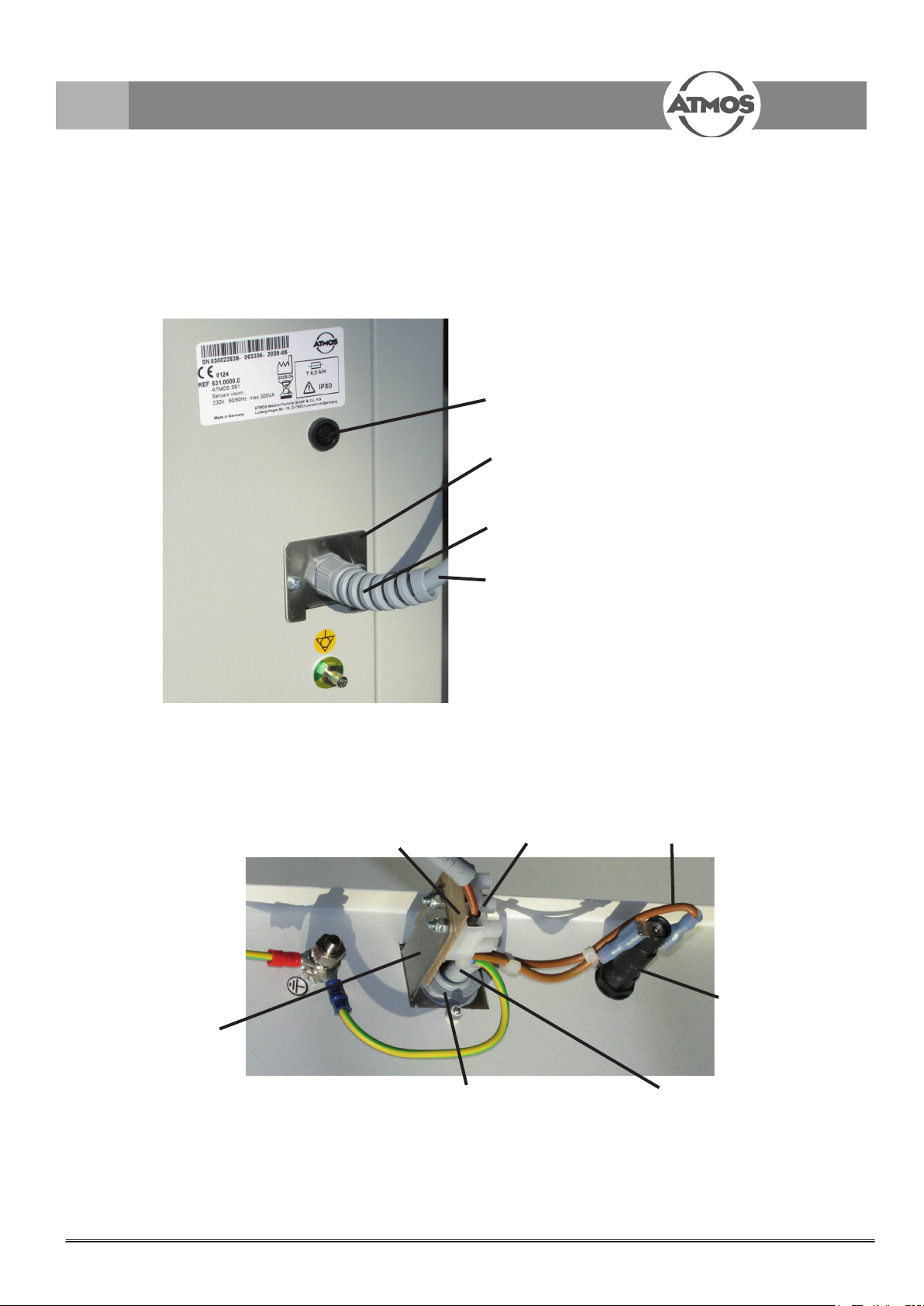
2.0 Termination 531.0030.0
If both options, camera and Strobo LED are used simultaneously the ATMOS S 61 Servant vision must be equip-
ped with a termination for the power supply cord (531.0030.0) instead of the demountable mains cable!
008.0704.1
Bayonet cap
530.1147.0 Mains connection bracket
008.0877.0 Cable gland
530.1147.0
Mains connection bracket
530.1148.0
Insulating
board
531.0168.0
cable S61 fi xed connection
Fig. 1
Fixed mains connection 531.0030.0
008.0026.1
Clamp 1P (3x)
531.0169.0
Cable fuse holder
008.0704.0
Fuse holder
Fig. 2
008.0877.0
Cable gland
531.0168.0
Cable S 61fi xed connection
5
Page 6

3.0 Assembly
Module Strobo
LED
Module camera
Bulkhead cable gland
Fig 3
Fig. 4
507.2212.1
Support for camera head
531.0144.0
Support for LED light source
Strobo LED
531.0095.0
Light barrier grip control
6
Page 7

3.0 Assembly
Ø 7-8 mm
Fig 5
Procedure
3.1. Assemble the fi xture for the camera head
• Open the side walls of the ATMOS S 61 Servant vision.
• Loosen the fastening screws of the upper part.
• Drill a 7-8 mm hole in the middle of the base for the camera
head fi xture (fi g 5).
• Assemble the fi xture for the camera head (fi g 6 and 7).
Fig 6
hose fi tting 531.0133.0
screw nut M32x1.5
Fig 7
hose piece
005.0004.0 0,23 m
3.2 Installation of the bulkhead cable gland
• Remove the protection cap for the cable gland.
• Insert the hose fi tting into the hole for the cable gland (fi g
8 and 9).
• Secure the hose fi tting on the rear side (fi g 8) with the
screws provided.
• Connect the hose to the hose fi tting as shown in Fig 3.
When the upper part is closed the hose must fi t into the
opening without kinking.
Fig 8
Fig. 9
bulkhead gland
7
Page 8

3.0 Assembly
1
Fig. 10
3.3 Installation of the module
• Position the module.
• Secure the module with 2 screws (051.0299.0) on the
bottom side.
• Guide the ribbon cable from the camera (
along the right side of the cabinet.
1
FIg. 10)
• A small adapter board 531.2141.0 is integrated in the
ribbon cable
• Connect the camera cable to the PCB (Fig. 11).
• Guide the control cable for the grip control of the strobo-
scope light source towards the back, by leading it through
the middle of the cabinet opening on the rear side of the
module (Fig. 14).
• Pull the cable gland over the cable and fi t it into the ope-
ning.
• Connect the cable for the grip control to the corresponding
jack on the rear side of the Strobo LED (Fig 12, Fig 16).
Connection of the camera
on the control PCB
Fig. 12
Fig. 11
8
Page 9
3.0 Assembly
mains supply cable
531.0184.0
strain relief L
008.0879.0
Controll PCB
Bild 15
Fig.13
Module
Fig. 14
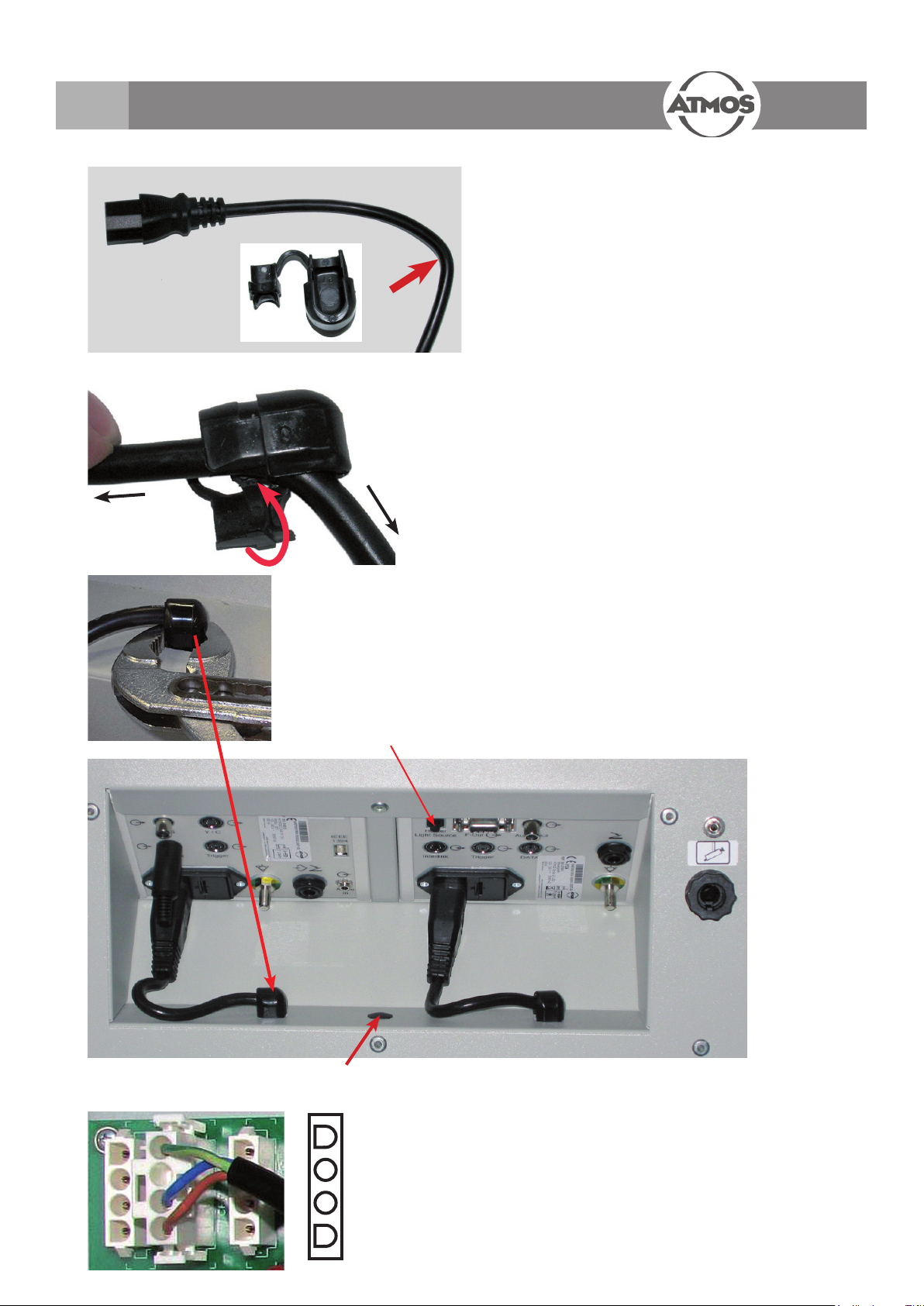
3.4 Assembly of the supply cables
Attention! The connector housing should only
be assembled after the supply cable is pultruded
through the cabinet opening! (Fig 16)
• Bend the supply cable into a right angle approx. 8 cm
behind the power connector, make sure the cable isn`t
twisted (Fig.16).
• Insert the cable in the strain relief (Fig 13).
• Press in the closure with a pliers. (Fig 14).
• Run the cable with the free end through the cabinet opening
from above. With the help of a pliers attach it to the strain
relief in the cabinet opening (fi g.15). Press the strain relief
into the cabinet opening as far as possible until it snaps
into place.
• Connect the power connector to the module.
• Connect the connector housing to the cable ends
(fi g.17)!
Fig. 16
Connection grip holder
Feed-through control cable
handle support
PE - green/yellow
Free
Neutral conductor
- blue
Attention! An exchange of the connections could
endanger persons due to an electric shock resp.
result in destruction of the controller of the ATMOS
S 61 Servant vision!
• Connect the power supply to the corresponding sockets on
the control board (page 12). Connect the modules amongst
one another acc. to page 10.
Fig. 17
Phase - brown
9
Page 10

3.0 Assembly
• Plug in the LED-Light source into the right bracket.
• Attach the camera head to the camera support.
• Guide the cable upwards through the slot of the right door, through the cable guide to the front panel of the module and
connect.
The LED-light source may only be connected to the Strobo LED and not to the camera.
10
Page 11

4.0 Connection Diagram
Foot Regulator
Handle Support
LED Lightsource
ATMOS Strobo LED
ATMOS Strobo 21 LED
1
1
Analogue Video System
VHS / S-VHS, TV,
PC Grabber Card
008.0858.0
1
008.0635.0
1
008.0635.0
008.0858.0
011.1293.0
507.5016.0
507.4750.0
2
008.0858.0
008.0859.0
Optionally possible
Typical connections
Only cameras „DATA“ 507.5100.0, 507.5130.0 and 507.5140.0
Only cameras „DV“ and „DV DATA“ 507.4200.0, 507.5100.0, 507.5130.0, 507.5140.0
All ATMOS cameras, except „DATA“ 507.5100.0, 507.5130.0 and 507.5140.0.
1
2
Legend:
ATMOS Cam 21 / 31 DV DATA
3
Attention! All connections are different!
. For cameras 531.2010.0 and 531.2020.0
3
Speaker
507.4260.0 (6/4)
507.4261.0 (6/6)
Computer
MS-Windows XP SP3 or later
IEEE 1394 Fire Wire
ATMOS MedDoc
Medical Archiving
Software
Interlink Dongle 507.4781.0
Accessory of ATMOS Strobo LED
If the ATMOS Strobo 21 LED is used in connection with an ATMOS
CAM 21 / 31 this dongle has to be plugged in in the „Interlink“ so-
cket of the camera.I n this case the camera settings are optimized
for the cameras stroboscopy mode especially for using the ATMOS
Strobo 21 LED
11
Page 12

5.0 Wiring diagram S 61 Servant vision
507.4600.0
bn
bn wt
LED-Modul
531.0190.0
531.0176.0
PAC-Modul
531.0102.0
Halogen 24V
531.0177.0
detail B detail C
PAC-Modul
531.0102.0
Halogen 15V
531.0177.0
detail A
wt
531.0103.0
531.0175.0531.0174.0
LED-Modul
506.7886.0
1
531.0193.0
531.0178.0
2
531.0194.0
531.0182.0
531.0095.0
531.0183.0
Fan
507.4084.0
507.4094.0
foot switch PCB
Handgriffhalter
Strobo CAM
531.0192.0
CAM
510.1691.0
531.1080.0
endoscope heating
531.0180.0
531.0184.0
Strobo LED
531.0184.0
Ch4
2
1
to C
see details A
bn
bubn
Ch1
531.0104.0
531.0179.0
Ch3
Light Control
531.0101.0
Ch2
Ch2
531.0182.0
531.0178.0
531.0183.0
123
T6,3A
T10,0A
0V
15V
24V0V
115V
127V
230V
100V
bu
bn
PE
Power Supply
011.1265.0
531.0181.0
yw/gn
PELN
bu
bn
Ch1
531.0189.0
front panel
yw/gn
531.0187.0
008.0388.0
mains switch
bn bn
Ch4
Ch3
531.0173.0
bu bu
531.0188.0
bn
531.0169.0
Permanent Instalation
T6,3A
housing
531.0186.0
yw/gn
yw/gn
531.0185.0
potential equalization
12
headlamp hook
n.c.
wt
detail D
and E
see detail D
yw/gn
bn
bu
008.0388.0
mains inlet
531.0198.0 / 531.0199.0
531.0198.0 / 531.0199.0
531.0198.0 / 531.0199.0
light barrier channel 1
light barrier channel 2
br
wt
br
n.o.
com
531.0172.0
wt
2
008.0849.0
n.o.
1
detail E microscope
3
531.0171.0
br
3
1
com
531.0198.0 / 531.0199.0
light barrier channel 3
light barrier channel 4
531.0168.0
Light Display
531.0100.0
531.0188.0
531.0191.0
Detachable Instalation
008.0821.0
507.0859.1
Page 13

6.0 Control board/ connections
power supply
ATMOS Strobo 21 LED
power supply camera
Interlink cable
from camera
13
Page 14

7.0 Parts list
System REF Designation Remarks
531.0030.0
Installation kit
termination
531.20XX.XX Option
camera
531.2050.0
Option
ATMOS Strobo 21 LED
530.1147.0 Mains inlet bracket
008.0877.0 Cable gland
530.1148.0 Insulation board
008.0026.1 Clamp 1P lustre terminal 3x
531.XXXX.X Camera module pre-assembly depending on option and camera type
507.2212.1 Camera support
008.0844.0 Cable FBAS Cinch / Cinch
011.1293.0 Adapter Cinch / BNC
008.0671.0 Cable S-VHS 2 m
531.0184.0 Mains connection cable connector housing 4P not mounted
008.0879.0 Strain relief L for mains connection cable
011.0962.0 Connector housing for mains connection cable connection PCB
507.4034.0 Foot switch
507.4260.0 Cable IEEE1394 6/4 FireWire large/small
507.4261.0 Cable IEEE1394 6/6 Firewire large / large
008.0859.0 Adapter Cinch/stereo 3.5 for audio cable of the Strobo LED
507.4750.0 Control cable Cam-S61 Camera adapter board 531.2141.0
531.2141.0 Adapter board between camera and S61
531.7004.0 Control cable II Cam-S61 adapter board 531.2141.0 – control board ATMOS S 61 Servant
507.4750.0 Cable Interlink Cam-Strobo
531.0159.0
008.0858.0 Cable Audio Cinch/Cinch mono
008.0859.0 Adapter Cinch/ Stereo 3.5
507.4772.0 Foot control ATMOS Strobo LED
507.4600.0 Light source LED
507.4780.0 Microphone
507.4781.0 Dongle connector Connection interlink for Cams 531.2010.0 and 531.2020.0
531.0095.0 Fork light barrier
531.0144.0 Grip holder - light support for LED Light source
008.0732.0 Bushing For cable light barrier
531.0184.0 Mains connection cable
008.0879.0 Strain relief L For mains connection cable
011.0962.0 Connector housing For mains connection cable connection PCB
Installation module ATMOS Strobo
21 LED
14
Page 15

Page 16

 Loading...