

Page 1

Operation and maintenance handbook
ATMOS
Portable screw compressor
ATMOS PDK 33
ATMOS Chrást s.r.o.; Plzeˇnská 149; 330 03 Chrást; Czech Republic
Tel.:
Fax.:
+420 / 377 860 - 181
+420 / 377 860 - 111
+420 / 377 745 247
+420 / 377 945 379
At 2020/N
Version
X.11.2016
Page 2

Page 3

CONTENTS
General description . . . . . . . . . . . . . . . . . . . . . . . . . . . . . . . . . . . . . . . . . . . . . . . . . . . . . 2
Guarantee conditions . . . . . . . . . . . . . . . . . . . . . . . . . . . . . . . . . . . . . . . . . . . . . . . . . 2
Drawings, diagrams, descriptions and explanations . . . . . . . . . . . . . . . . . . . . . . . . . . . . . . . . . . 4
Dimensions . . . . . . . . . . . . . . . . . . . . . . . . . . . . . . . . . . . . . . . . . . . . . . . . . . . . . . . 4
Safety regulations . . . . . . . . . . . . . . . . . . . . . . . . . . . . . . . . . . . . . . . . . . . . . . . . . . . 5
Technical parameters . . . . . . . . . . . . . . . . . . . . . . . . . . . . . . . . . . . . . . . . . . . . . . . . . 6
Safety system . . . . . . . . . . . . . . . . . . . . . . . . . . . . . . . . . . . . . . . . . . . . . . . . . . . . . 7
Functional diagram . . . . . . . . . . . . . . . . . . . . . . . . . . . . . . . . . . . . . . . . . . . . . . . . . . . 9
Description of the workstation(s) . . . . . . . . . . . . . . . . . . . . . . . . . . . . . . . . . . . . . . . . . . . . . 10
Description of the intended use . . . . . . . . . . . . . . . . . . . . . . . . . . . . . . . . . . . . . . . . . . . . . . 11
Warnings concerning ways in which the machinery must not be used . . . . . . . . . . . . . . . . . . . . . . . . 12
Assembly, installation and connection instructions . . . . . . . . . . . . . . . . . . . . . . . . . . . . . . . . . . 13
Instructions relating to installation and assembly for reducing noise or vibration . . . . . . . . . . . . . . . . . 14
Instructions for the putting into service and usage of the machinery . . . . . . . . . . . . . . . . . . . . . . . . . 15
Commissioning . . . . . . . . . . . . . . . . . . . . . . . . . . . . . . . . . . . . . . . . . . . . . . . . . . . . . 15
Before starting . . . . . . . . . . . . . . . . . . . . . . . . . . . . . . . . . . . . . . . . . . . . . . . . . . . . . 15
Starting the machine . . . . . . . . . . . . . . . . . . . . . . . . . . . . . . . . . . . . . . . . . . . . . . . . . . 17
Stopping the machine . . . . . . . . . . . . . . . . . . . . . . . . . . . . . . . . . . . . . . . . . . . . . . . . . 18
Emergency shut-down . . . . . . . . . . . . . . . . . . . . . . . . . . . . . . . . . . . . . . . . . . . . . . . . . 19
Re-starting after an emergency shut-down . . . . . . . . . . . . . . . . . . . . . . . . . . . . . . . . . . . . . . 19
Machine monitoring . . . . . . . . . . . . . . . . . . . . . . . . . . . . . . . . . . . . . . . . . . . . . . . . . . 19
Operation in hard climatic conditions . . . . . . . . . . . . . . . . . . . . . . . . . . . . . . . . . . . . . . . . . 20
Information about the residual risks . . . . . . . . . . . . . . . . . . . . . . . . . . . . . . . . . . . . . . . . . . . 21
Instructions on the protective measures . . . . . . . . . . . . . . . . . . . . . . . . . . . . . . . . . . . . . . . . . 22
Battery . . . . . . . . . . . . . . . . . . . . . . . . . . . . . . . . . . . . . . . . . . . . . . . . . . . . . . . . 22
Essential characteristics of tools . . . . . . . . . . . . . . . . . . . . . . . . . . . . . . . . . . . . . . . . . . . . . 23
The conditions in which the machinery meets the requirement of stability . . . . . . . . . . . . . . . . . . . . . 24
Parking . . . . . . . . . . . . . . . . . . . . . . . . . . . . . . . . . . . . . . . . . . . . . . . . . . . . . . . . . 24
Instructions with a view to ensuring that transport, handling and storage operations can be made safely . . . 25
Machine transport . . . . . . . . . . . . . . . . . . . . . . . . . . . . . . . . . . . . . . . . . . . . . . . . . . . 25
Coupling the tow bar with suspension eye . . . . . . . . . . . . . . . . . . . . . . . . . . . . . . . . . . . . . . 25
Uncoupling the tow bar with suspension eye . . . . . . . . . . . . . . . . . . . . . . . . . . . . . . . . . . . . . 25
Coupling the tow bar with ISO 50 suspension . . . . . . . . . . . . . . . . . . . . . . . . . . . . . . . . . . . . 25
Uncoupling the tow bar with ISO 50 suspension . . . . . . . . . . . . . . . . . . . . . . . . . . . . . . . . . . . 26
Long term storage preparation . . . . . . . . . . . . . . . . . . . . . . . . . . . . . . . . . . . . . . . . . . . . . 26
1 At 2020/N
X.11.2016
Page 4

Decommissioning . . . . . . . . . . . . . . . . . . . . . . . . . . . . . . . . . . . . . . . . . . . . . . . . . . . 27
Operating method to be followed in the event of accident or breakdown . . . . . . . . . . . . . . . . . . . . . . 28
Troubleshooting . . . . . . . . . . . . . . . . . . . . . . . . . . . . . . . . . . . . . . . . . . . . . . . . . . . . 28
Emergency shut-down . . . . . . . . . . . . . . . . . . . . . . . . . . . . . . . . . . . . . . . . . . . . . . . . . 29
Description of the adjustment and maintenance operations . . . . . . . . . . . . . . . . . . . . . . . . . . . . . . 30
Waste products . . . . . . . . . . . . . . . . . . . . . . . . . . . . . . . . . . . . . . . . . . . . . . . . . . . . . 30
Exchange of suspension equipment . . . . . . . . . . . . . . . . . . . . . . . . . . . . . . . . . . . . . . . . . . 30
Oil scavenge line . . . . . . . . . . . . . . . . . . . . . . . . . . . . . . . . . . . . . . . . . . . . . . . . . . . . 31
Compressor oil filter . . . . . . . . . . . . . . . . . . . . . . . . . . . . . . . . . . . . . . . . . . . . . . . . . . 31
Assembly . . . . . . . . . . . . . . . . . . . . . . . . . . . . . . . . . . . . . . . . . . . . . . . . . . . . . . . . 31
Oil separator insert . . . . . . . . . . . . . . . . . . . . . . . . . . . . . . . . . . . . . . . . . . . . . . . . . . . 31
Oil and water cooler . . . . . . . . . . . . . . . . . . . . . . . . . . . . . . . . . . . . . . . . . . . . . . . . . . 32
Compressor drive . . . . . . . . . . . . . . . . . . . . . . . . . . . . . . . . . . . . . . . . . . . . . . . . . . . 32
Alternator belt . . . . . . . . . . . . . . . . . . . . . . . . . . . . . . . . . . . . . . . . . . . . . . . . . . . . . 32
Air filter . . . . . . . . . . . . . . . . . . . . . . . . . . . . . . . . . . . . . . . . . . . . . . . . . . . . . . . . . 33
Ventilation . . . . . . . . . . . . . . . . . . . . . . . . . . . . . . . . . . . . . . . . . . . . . . . . . . . . . . . 33
Cooling fan . . . . . . . . . . . . . . . . . . . . . . . . . . . . . . . . . . . . . . . . . . . . . . . . . . . . . . . 33
Fuel system . . . . . . . . . . . . . . . . . . . . . . . . . . . . . . . . . . . . . . . . . . . . . . . . . . . . . . . 33
Fuel filter . . . . . . . . . . . . . . . . . . . . . . . . . . . . . . . . . . . . . . . . . . . . . . . . . . . . . . . . 34
Fuel filter water separator (if installed) . . . . . . . . . . . . . . . . . . . . . . . . . . . . . . . . . . . . . . . . 34
Hoses . . . . . . . . . . . . . . . . . . . . . . . . . . . . . . . . . . . . . . . . . . . . . . . . . . . . . . . . . . 34
Electrical system . . . . . . . . . . . . . . . . . . . . . . . . . . . . . . . . . . . . . . . . . . . . . . . . . . . . 34
Battery . . . . . . . . . . . . . . . . . . . . . . . . . . . . . . . . . . . . . . . . . . . . . . . . . . . . . . . . . 35
Additional lubricator (if installed) . . . . . . . . . . . . . . . . . . . . . . . . . . . . . . . . . . . . . . . . . . . . 35
Pressure system . . . . . . . . . . . . . . . . . . . . . . . . . . . . . . . . . . . . . . . . . . . . . . . . . . . . 35
Compressor oil . . . . . . . . . . . . . . . . . . . . . . . . . . . . . . . . . . . . . . . . . . . . . . . . . . . . . 35
Compressor oil specification . . . . . . . . . . . . . . . . . . . . . . . . . . . . . . . . . . . . . . . . . . . . . . 35
Speed and pressure control adjustment . . . . . . . . . . . . . . . . . . . . . . . . . . . . . . . . . . . . . . . . 36
Engine . . . . . . . . . . . . . . . . . . . . . . . . . . . . . . . . . . . . . . . . . . . . . . . . . . . . . . . . . 36
Lubrication . . . . . . . . . . . . . . . . . . . . . . . . . . . . . . . . . . . . . . . . . . . . . . . . . . . . . . . 36
Engine oil . . . . . . . . . . . . . . . . . . . . . . . . . . . . . . . . . . . . . . . . . . . . . . . . . . . . . . . . 36
Engine oil specification . . . . . . . . . . . . . . . . . . . . . . . . . . . . . . . . . . . . . . . . . . . . . . . . . 37
Engine oil filter . . . . . . . . . . . . . . . . . . . . . . . . . . . . . . . . . . . . . . . . . . . . . . . . . . . . . 37
Inspection of the alternator belt tension . . . . . . . . . . . . . . . . . . . . . . . . . . . . . . . . . . . . . . . . 37
Running gear / wheels . . . . . . . . . . . . . . . . . . . . . . . . . . . . . . . . . . . . . . . . . . . . . . . . . 37
Wheel bearings . . . . . . . . . . . . . . . . . . . . . . . . . . . . . . . . . . . . . . . . . . . . . . . . . . . . . 37
Tyres pressure . . . . . . . . . . . . . . . . . . . . . . . . . . . . . . . . . . . . . . . . . . . . . . . . . . . . . 37
At 2020/N
X.11.2016
2
Page 5

Brakes . . . . . . . . . . . . . . . . . . . . . . . . . . . . . . . . . . . . . . . . . . . . . . . . . . . . . . . . . 37
Wheel brake adjustment . . . . . . . . . . . . . . . . . . . . . . . . . . . . . . . . . . . . . . . . . . . . . . . . 37
Adjusting the overrun braking system (Knott) . . . . . . . . . . . . . . . . . . . . . . . . . . . . . . . . . . . . . 37
Tightening torques . . . . . . . . . . . . . . . . . . . . . . . . . . . . . . . . . . . . . . . . . . . . . . . . . . . 40
Instructions designed to enable adjustment and maintenance . . . . . . . . . . . . . . . . . . . . . . . . . . . . 41
Maintenance schedule . . . . . . . . . . . . . . . . . . . . . . . . . . . . . . . . . . . . . . . . . . . . . . . . . 41
Notice for maintenance . . . . . . . . . . . . . . . . . . . . . . . . . . . . . . . . . . . . . . . . . . . . . . . . 42
Maintenance . . . . . . . . . . . . . . . . . . . . . . . . . . . . . . . . . . . . . . . . . . . . . . . . . . . . . . 43
Before maintenance . . . . . . . . . . . . . . . . . . . . . . . . . . . . . . . . . . . . . . . . . . . . . . . . . . 43
Minimal pressure valve . . . . . . . . . . . . . . . . . . . . . . . . . . . . . . . . . . . . . . . . . . . . . . . . . 43
Before removing of covers . . . . . . . . . . . . . . . . . . . . . . . . . . . . . . . . . . . . . . . . . . . . . . . 44
Maintenance on a running machine . . . . . . . . . . . . . . . . . . . . . . . . . . . . . . . . . . . . . . . . . . 44
Maintenance completion . . . . . . . . . . . . . . . . . . . . . . . . . . . . . . . . . . . . . . . . . . . . . . . . 44
Specifications of the spare parts . . . . . . . . . . . . . . . . . . . . . . . . . . . . . . . . . . . . . . . . . . . . . 45
Airborne noise emissions . . . . . . . . . . . . . . . . . . . . . . . . . . . . . . . . . . . . . . . . . . . . . . . . . 46
Non-ionising radiation . . . . . . . . . . . . . . . . . . . . . . . . . . . . . . . . . . . . . . . . . . . . . . . . . . . 47
3 At 2020/N
X.11.2016
Page 6

GENERAL DESCRIPTION
Contents of this Operation and maintenance handbook are property of ATMOS Chrást company. This handbook is altered
and updated regularly for each production series and it may not be copied without written permission.
The producer does not assume responsibility for errors occurring from this translation.
This Handbook contains all information necessary for routine operation and maintenance of the machine. More detailed
information and procedures for larger repairs are not included in this Handbook but they are available at authorized service
partners of ATMOS Chrást company.
There may appear minor inconsistencies between the Handbook and the actual machine due to improvements of the
machine. Ask your dealer if you have any questions or problems.
The machine design complies with relevant EU regulations. This CE Declaration of conformity is losing its validity in case of
any not-approved modification of individual machine parts and components.
All parts, accessories, piping, hoses and connections through which the compressed air flows should be
∙ of guaranteed quality and approved by the manufacturer for intended use,
∙ approved for the nominal pressure level at least equal to machine maximum operation pressure,
∙ usable in contact with compressor oil and coolant,
∙ delivered together with the Handbook for installation and safe operation of the machine.
You will be provided with all details concerning suitability of individual parts use by selling and servicing centres of ATMOS
Chrást company.
The use of other than original spare parts, fluids and lubricants given in ATMOS Spare Parts Catalogue could lead to the
situation, for which ATMOS Chrást company cannot bear any responsibility. In such a case ATMOS Chrást company does
not take any responsibility for potential damage.
Read the Handbook carefully before operating the machine to fully understand its operation and maintenance requirements.
Guarantee the Operation and maintenance handbook is always at disposal directly by the machine.
Guarantee the maintenance personnel are always professionally trained and acquainted with instructions for operation and
maintenance.
Make sure the operating personnel is acquainted with all safety signs and instructions for machine operation before putting it
into operation or under maintenance.
Make sure all protective covers are installed and shut before putting the machine into operation.
A weekly visual check must be made on all fasteners/fixing screws securing mechanical parts. Notably, safety-related parts
such as a coupling hitch, drawbar components, road-wheels, and a lifting bail should be checked for absolute security.
All components which are loose, damaged or out of order must be repaired without delay.
GUARANTEE CONDITIONS
The manufacturer or its authorized service centre provides all guarantee and after-guarantee service.
If necessary, please contact the manufacturer or its authorized service centre where you will be provided with all necessary
information and recommendations.
Guarantee does not cover
∙
damage caused by incompetent operation and maintenance carried out in contrast with instructions in the Operation
and Maintenance Handbook,
∙ damage caused by incompetent transport, manipulation (car accident) and storage,
∙ damage caused by the machine operation in extremely aggressive surroundings,
∙ consumable materials (filter and separator inserts, V-belts, etc.),
At 2020/N
X.11.2016
4
Page 7

∙ air end damage caused by corrosion or oil degradation influenced by omission of required inspections.
Guarantee is void
∙ if filter inserts, separator inserts and other materials have not been replaced in intervals prescribed in the Handbook,
∙ if the machine has been used for other purposes than those defined in the Handbook,
∙ if damage has been caused by improper location of the machine in relation to cooling air supply and drain,
∙ if other than prescribed fuels and oils have been used,
∙ if other than original spare parts have been used,
∙ if seals have been damaged,
∙
if the Service Booklet of the machine has not been presented to service engineers during a guarantee inspection or if
prescribed operations have not been logged to the Handbook,
∙ if the machine breakdown has not been caused by a defect due to workmanship,
∙ if there has been and intervention carried out on the machine construction,
∙ if the machine has been repaired by other subjects than the manufacturer or its authorised service centre,
∙
if the machine has been handed over another owner without a technical inspection carried out by the manufacturer or
its authorised service centre,
∙
if prescribed guarantee inspections have not been carried out on time and have not been logged to this Service Booklet
with a coupon sent to the manufacturer,
∙ if a claim has not been lodged in writing at the latest on the 10th day following the day a defect occurred,
∙ if damage has been caused by a third person because of insufficient safety precautions,
∙
if the machine has not been put into operation, operating personnel have not been trained by the manufacturer’s
authorized service centre and this has not been logged to the Service Booklet,
∙ if the registration card has not been filled in.
5 At 2020/N
X.11.2016
Page 8
DRAWINGS, DIAGRAMS, DESCRIPTIONS AND EXPLANATIONS
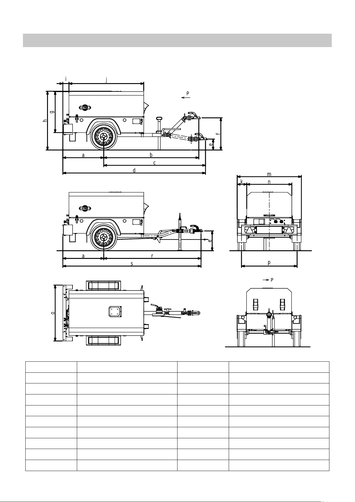
DIMENSIONS
Dimension [mm] PDK 33 Dimension [mm] PDK 33
a 750 j 1565
b 2395 k 200
c 2530 m 1485
d 3350 n 1085
e 430 o 1280
f 845 p 1295
g 851 r 2485
h 1265 s 3235
i 92
At 2020/N
X.11.2016
6
Page 9
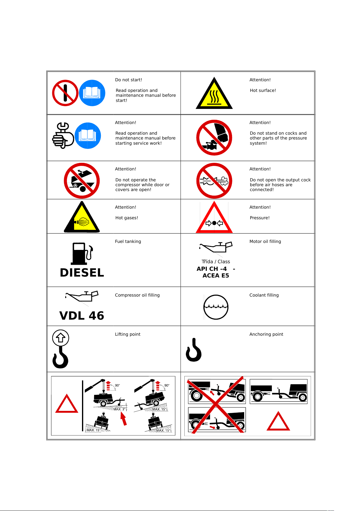
SAFETY REGULATIONS
Do not start!
Read operation and
maintenance manual before
start!
Attention!
Hot surface!
Attention!
Read operation and
maintenance manual before
starting service work!
Attention!
Do not stand on cocks and
other parts of the pressure
system!
Attention!
Do not operate the
compressor while door or
covers are open!
Attention!
Do not open the output cock
before air hoses are
connected!
Attention!
Hot gases!
Attention!
Pressure!
DIESEL
Fuel tanking
Třída / Class
API CH –4 -
ACEA E5
Motor oil filling
VDL 46
Compressor oil filling Coolant filling
Lifting point Anchoring point
THIS TYPE OF MACHINE IS INTENDED FOR OUTSIDE OF EU EXPORT ONLY.
7 At 2020/N
X.11.2016
Page 10

TECHNICAL PARAMETERS
Compressor PDK 33-7 PDK 33-10 PDK 33-12
Air end B 100
–1
Nominal capacity [m
Nominal overpressure [bar] 7,0 10,0 12,0
Safety valve setting [bar] 10,0 12,5 14,5
Ambient temperature [∘C] –10 ÷ 50
Max. outlet temperature [∘C] 110
Cooling system oil injection
Compressor oil filling volume [l] 7,2 7,2 7,2
Transmission oil filling vol. [l] - - -
Max. oil system temperature [∘C] 110,0 110,0 110,0
Max. oil system overpressure [bar] 8,6 11,6 13,5
3
· min
] 5,0 3,8 3,2
Outlet cocks 2x G 3/4“
(KAG3/4“)
2x G 3/4“
(KAG3/4“)
Engine PDK 33
Type/Model Kubota V1505-T
Cylinders 4
Load speed [min–1] 3000
Idle speed [min–1] 1500 ± 50
Oil filling vol. [l] 6,7
Fuel tank vol. [l] 70,0
Coolant filling vol. [l] 4,0
Battery [V / Ah] 12 / 44
Noise emissions PDK 33
Sound power level L
WA
Sound pressure level L
pA
[dB(A)/pW] 98
[dB(A)/20
𝜇Pa
]
78
Undercarriage (braked/unbraked) PDK 33
2x G 3/4“
(KAG3/4“)
Type/Model Knott
Max. transport velocity* [km/h] 80
Total mass [kg] 750
Max. mass on axle [kg] 750
Max. mass on suspension [kg] 75
At 2020/N
8
X.11.2016
Page 11

* Recommended transport velocity PDK 33
Max. design velocity [km/h] 80
Common roads [km/h] 80
Gravel roads [km/h] 50
Dirty tracks, etc. [km/h] 30
Ground [km/h] 10
Wheels and tyres PDK 33
Wheel discs 4.5J x 13 - 100x4
Tyres 155 R13 (155/80 R13)
Tyre pressure [kPa/bar] 250 / 2.5
SAFETY SYSTEM
Consists of:
∙ low engine oil pressure switch,
∙ high air end discharge temperature switch,
∙ high engine coolant temperature switch,
∙ alternator / drive belt failure circuit.
Low engine oil pressure switch
At three month intervals, test the engine oil pressure switch circuit as follows:
∙ Start the machine.
∙ Run the machine at idle speed.
∙
Disconnect the switch connector. Short-circuit contacts in the connector. The machine should shut down (after 2
second delay).
At twelve month intervals, test the engine oil pressure switch circuit as follows:
∙ Remove the switch from the machine.
∙ Connect the switch to an independent low pressure supply (either air or oil).
∙ The switch should be switch offat 1.0 bar.
∙ Reinstall the switch.
Temperature switch(es)
At three month intervals, test the temperature switch circuit(s) as follows:
∙ Start the machine.
∙ Run the machine at idle speed.
∙
Disconnect the switch connectors one by one. Short-circuit contacts in the connector. The machine should shut down
(after 2 second delay).
∙ Reconnect the switches.
High air end discharge temperature switch(es)
At twelve month intervals, test the air end discharge temperature switch(es) by removing it (them) from the machine and
immersing in a bath of heated oil. The switch should be switch offat 110 ± 5∘C. Reinstall the switch(es).
High engine coolant temperature switch
At twelve month intervals, test the engine coolant temperature switch removing it from the machine and immersing in a bath
of heated oil. The switch should be switch offat 110 ± 3∘C Reinstall the switch.
9 At 2020/N
X.11.2016
Page 12

Alternator / drive belt failure circuit
Test the circuit before each machine start as follows:
1. Turn the key to ON position and check that the recharge indicator is on.
2. Complete the machine starting sequence.
3. The recharge indicator should switch off.
At 2020/N
X.11.2016
10
Page 13

FUNCTIONAL DIAGRAM
Explanatory
notes
1 air outlet 6 air end
2 nozzle / min. pres. valve 7 engine
3 manometer 8 oil cooler
4 separator tank 9 oil filter
5 safety valve 10 thermostat
oil
air
11 At 2020/N
X.11.2016
Page 14

DESCRIPTION OF THE WORKSTATION(S)
Does not apply.
At 2020/N
X.11.2016
12
Page 15

DESCRIPTION OF THE INTENDED USE
Compressed air can be dangerous when used improperly! Before any operation, maintenance or machine repairs - the
pressure system should be completely empty (free from over-pressure). Besides this, the machine shall be secured against
accidental starting.
Guarantee the machine will be operated on nominal pressure only and the compressor operating personnel are acquainted
with this instruction. Pressure level of compressed air equipment connected to the machine must be at least the same as the
machine nominal pressure level.
Warning
Under no circumstances compressed air is allowed to be used for direct human respiration!
Warning
Compressed air can cause serious injury or death. Relieve overpressure before removing filler plugs/caps, fittings or covers.
Warning
Residual air pressure in the air system can cause serious injury or death. Always carefully vent the air supply
line to tools or cocks before any maintenance.
Output air contains a small amount of compressor oil. For this reason it is necessary to verify the compatibility of all used
equipment connected to the compressed air source.
If compressed air flows into the closed space, it is necessary to provide cooling of the air.
All personnel should always wear proper protective clothes when working with compressed air.
All pressure loaded parts including the pressure hoses should be tested regularly. No signs of damage should be observed
and all parts should be used in conformance with instructions for their use and/or for their intended purpose.
Avoid contact with compressed air.
The safety valve on the oil separator should be tested regularly according to given instructions.
When the machine is stopped, compressed air can flow back into the compressor system from devices or systems
downstream of the machine, unless the service valve is closed. Install a back pressure valve at the machine outlet cocks to
avoid reverse flow in the event of an unexpected shut-down when the outlet cocks are open.
Disconnected air hoses whip and can cause serious injury or death. Always attach a safety flow restrictor to each hose
according to safety rules.
The supposed ways of the machine use are presented below. If the machine should be used in an unusual way or in an
unusual surroundings, please contact the manufacturer.
This machine has been designed and supplied for use under following conditions only:
∙ compressing the usual air that does not contain any additional gases, vapours or additives,
∙ the machine will be operated at temperatures shown in chapter Technical parameters on page 6 ,
∙ the machine will be operated in conformance with this Operation and maintenance handbook.,
∙ the generator will be operated up to nominal current and voltage (when the machine is equipped with a generator).
13 At 2020/N
X.11.2016
Page 16

WARNINGS CONCERNING WAYS IN WHICH THE MACHINERY MUST NOT BE
USED
Due to machine design it is not possible to use the machine at locations where danger of explosion exists. If the machine is
to be operated in such places, all local rules, standards and regulations must be fulfilled by adding of suitable supplementary
devices, such as gas detectors, combustion products removal, safety valves, etc. to eliminate all risks.
Warning
Air discharged from this machine may contain carbon monoxide or other contaminants which will cause serious
injury or death. Do not breathe this air.
The machine produces loud noise with its doors open or a service valve vented. Extended exposure to loud noise can cause
hearing loss. Always wear hearing protectors when the doors are open or the service valve is vented.
Warning
Never inspect or service the machine without previous disconnection of battery cables to prevent accidental
starting of the machine.
Do not use petroleum products (solvents or fuels) under high pressure as this can penetrate the skin and result in serious
illness. Wear eye protection while cleaning the machine with compressed air to prevent eye injury.
Rotating fan blades can cause serious injury. Do not operate the machine without a fan guard installed.
Avoid contact with hot surfaces (an engine exhaust manifold and pipping, an air receiver and air discharge pipping, etc.).
Never use volatile substances (e. g. ether) as a starting aid.
Never operate the machine with guards, covers or screens removed. Keep hands, hair, clothing, tools, etc. away from
moving parts.
The machine is not allowed to be used :
∙ as a direct supply of pressurized air for respiration purposes,
∙ for indirect human consumption without suitable air filtration and purity check,
∙ out of temperature range specified in the general information section of this handbook,
∙ in surroundings containing explosive gases or vapours,
∙ in areas with no reliable device for combustion products removal,
∙ with accessories, components, lubricants and coolants not recommended by ATMOS Chrást company,
∙ for operation with not functional safety or control elements of without these elements.
At 2020/N
X.11.2016
14
Page 17

ASSEMBLY, INSTALLATION AND CONNECTION INSTRUCTIONS
If more than one compressor are connected to the pneumatic equipment at the same time, every machine should be
equipped with a non-return flap valve to avoid back air streaming through the output cocks into the machine.
15 At 2020/N
X.11.2016
Page 18

INSTRUCTIONS RELATING TO INSTALLATION AND ASSEMBLY FOR REDUCING NOISE OR VIBRATION
The compressor body is equipped with noise absorption panels used for noise control. The machine cannot be operated
without these noise absorption panels.
The machine was designed to reduce all risks caused by vibrations to the lowest level.
At 2020/N
X.11.2016
16
Page 19

INSTRUCTIONS FOR THE PUTTING INTO SERVICE AND USAGE OF THE MACHINERY
COMMISSIONING
After obtaining of the machine and before putting it in into service, it is important to adhere strictly to the instructions given
below in Before starting.
Make sure that the operating personnel read and understand the rules and follow the instructions given in this handbook
before the machine operation or maintenance.
Before towing of the machine, make sure the tyre pressures are correct (see chapter Drawings, diagrams, descriptions
and explanations on page 4 ) and that the handbrake works properly (see chapter Description of the adjustment and
maintenance operations on page 30 ). Before towing of the machine in reduced visibility conditions, make sure that the lights
work properly (where installed).
Make sure all packaging and transport materials are removed.
Make sure that the correct tow hitch, lifting or binding devices are used when the machine is transported or lifted.
When choosing the working position of the machine, be sure that there is sufficient ventilation system for cooling and exhaust
fumes and required minimal working space is observed (wall, ceiling, etc.).
Adequate clearance needs to be allowed around and above the machine to permit safe access for operation and maintenance.
The air inlet should be secured against any free objects sucked into it.
Make sure that the machine is positioned on a stable foundation. Any risk of movement should be removed by suitable
means, especially it is necessary to avoid straining of outlet piping system.
Attach the battery cables to the battery clamps and tighten them securely. Attach the positive pole (+) cable before attaching
the negative pole (-) cable.
Warning
Nominal pressure of all air pressure equipment installed in or connected to the machine must be equal or
greater than nominal pressure of the machine. All materials used must be compatible with the compressor oil
(see chapter Drawings, diagrams, descriptions and explanations).
Warning
If more than one compressor are connected to one common air pressure equipment simultaneously, make sure
back pressure valves and control valves are installed, so that one machine cannot accidentally be pressurised /
over pressurised by another.
Warning
If flexible discharge hoses carry more than 7 bar pressure then it is recommended that safety binding is used on
the hoses ends.
BEFORE STARTING
1.
Install the machine on a level floor (max. allowed slope in longitudinal and transverse axis is 15∘) and secure it against
movement (pull the handbrake, use wedges).
2. Check the engine oil level according to the instructions in the handbook.
3.
Check the separator oil level. Check there is no leaking in the oil circuit. Check that all outlet plugs and a filling nozzle
of the separator vessel are tightened.
4. Check the coolant level (the machine is positioned horizontally).
5. Check the fuel filter (opt. drain water so that the filter contains only fuel).
6. Check the diesel oil level in the fuel tank.
7. Check the air filter indicator. (see chapter Description of the adjustment and maintenance operations on page 30 ).
17 At 2020/N
X.11.2016
Page 20

8. Open the outlet cocks to relieve the pressure. Then close the cocks again.
9. Close all covers/doors of the machine.
When refuelling
∙ switch off the engine,
∙ do not smoke,
∙ do not use naked lights,
∙ keep diesel oil away from hot surfaces,
∙ wear personal protective equipment.
Warning
Use diesel oil only! Biodiesel or its mixture with diesel oil may cause the engine damage. Use of biodiesel will void the manufacturer’s guarantee!
Do not overfill either the engine or the compressor with oil.
To maintain long working life of the machine it is very important to follow the instructions from this Handbook, especially
when the machine is new. It is not recommended to operate the machine at maximum load during the first 50 working hours.
Warning
Do not operate the machine with its bonnet / covers open. This may cause the
machine overheating and the operation staff are exposed to high levels of noise.
Do not move or otherwise manipulate with the machine when it is working.
Warning
Before putting the machine into operation after a longer shut-down (more than 6 months long), please contact
the ATMOS Service centre.
When starting or operating the machine in temperatures below 0∘C, make sure that the operation of the control system, the
unloader valves, the safety valve, and the engine are not damaged by ice or snow and that inlet and outlet pipes and drains
are clear of ice and snow.
At 2020/N
X.11.2016
18
Page 21

STARTING THE MACHINE
Warning
Never use volatile substances (e. g. ether) as a starting aid!
All compressor functions are controlled by the embedded controller.
1. Fully close all outlet cocks.
2. Turn the key to switch on the controller.
3. Check, if the controller does not indicate any error or warning (K) on LCD, make sure that ALARM light (6) is not on.
4. Press the green START button (1) to start the machine.
5. Compressor starts the heating procedure and starts after given delay.
6. After warming up the pressure-control is activated (icon (A)) and the compressor delivers the air.
7. Open the outlet cocks, the machine works in automatic mode.
All compressor parameters are displayed on the controller LCD during the operation. To list between the screens, press UP
(4) or DOWN (5) buttons. The meaning of the icons is explained in the table.
Note
Some of the sensors might not be connected on all types, in this case these values will not be displayed.
Note
For smooth operation of the machine, let the engine warm up. Do not operate the engine at full load immediately
after it starts up. This will shorten the service life of the machine.
At temperature below 0∘C or if there are difficulties during the initial start up:
1. Open the outlet cocks fully, with no hoses connected.
2. Complete the starting procedure.
3. Close the outlet cocks once the engine runs evenly.
The machine should not be operated with the outlet cocks opened for a long period of time. Allow the engine to reach
operating temperature. When operating temperature is reached, the engine can be safely operated at full load.
Warning
Always disconnect the battery when starting the machine with alternative energy source!
Note
Always wear hearing protection when the machine is operated while the air is flowing from the open outlet cocks.
19 At 2020/N
X.11.2016
Page 22

1 STOP button
2 MENU button
3 START button
4 UP button
5 DOWN button
6 alarm
7 compressor running
A compressor loaded
B speed indicator
C running hours indicator
D engine status and timer
E engine oil pressure
F oil temperature
G fuel level indicator
H battery voltage
I outlet pressure
J inner pressure
K alarm
STOPPING THE MACHINE
1. Close the outlet cocks one by one.
2. Press the red STOP button (1).
3.
The compressor will close the suction regulator (unload), de-compress and cool down. After the given delay, the
machine stops.
4. After the machines stops, you can switch off the main key.
5.
During maintenance, etc. disconnect the battery and close the compressed air outlet cocks (disconnect the hoses) if
the machine is connected to the compressed air distribution system.
Warning
In emergency situation, the machine can be stopped by switching off the main key. This is not recommended for
regular operation, the compressor can be damaged permanently.
Warning
Do not stop the machine when loaded or operating with open cocks.
Warning
After stopping the machine, never release overpressure by opening the outlet cocks. There is a danger that
foamed oil could get into the outlet cocks.
At 2020/N
X.11.2016
20
Page 23

Warning
Never leave the machine idle with overpressure in the system.
Note
Once the engine stops, the unloader valve relieves the pressure automatically. If the unloader valve fails, the pressure must be released through outlet cocks and the failure must be fixed.
EMERGENCY SHUT-DOWN
In case of emergency, turn the switch to 0 (OFF) position.
RE-STARTING AFTER AN EMERGENCY SHUT-DOWN
After an emergency shut-down, find and solve the problem before an attempted re-start.
If the machine has been switched off for safety reasons, make sure the machine can be operated safely before an attempted
re-start.
Before re-starting the machine, follow the instructions in chapter Before starting and Starting the machine.
MACHINE MONITORING
1. Check periodically the oil and air circuit staunchness as well as the engine filling circuit.
2. Check the air operation overpressure. Its value must not exceed the set pressure limit.
3. Check the fuel level in the fuel tank.
4. No warning lights may flash during the machine operation.
With outlet cocks closed the engine speed should decrease to no-load level once the operation overpressure has been
5.
reached.
The machine should shut-down under these conditions:
∙ low engine oil pressure,
∙ high air end discharge temperature,
∙ high engine coolant temperature.
Warning
Provide adequate oil flow rate at low temperatures, never allow the outlet overpressure to fall below 3,5 bar.
Warning
The machine is over pressure during operation! There is a danger of injury when improperly handled.
Warning
All covers should be closed during the machine operation!
All covers should be closed when the machine is operated or transported on public roads. Rear triangle reflectors must be
visible at all times.
21 At 2020/N
X.11.2016
Page 24

OPERATION IN HARD CLIMATIC CONDITIONS
Operation during the winter season:
1. Check the electrolyte level and the battery capacity.
2. Use the engine oil designed for use in winter.
3. Use the diesel oil designed for use in winter.
4. For low temperatures under –5∘C consult the manufacturer due to the suitable compressor and engine oil use.
Operation at permanently increased temperatures:
1. Pay attention to regular cleaning of heat exchange surfaces of the coolers.
2. Consult the manufacturer due to the suitable compressor oil use.
Operation in an extremely dusty environment
1. Pay special attention to regular cleaning of heat exchange surfaces of the coolers.
2. Check the air intake filter regularly.
3. Reduce exchange intervals of the oil filter and the compressor and engine air filters.
4. Reduce exchange intervals of oil fillings according to the manufacturer’s recommendation.
At 2020/N
X.11.2016
22
Page 25

INFORMATION ABOUT THE RESIDUAL RISKS
Following materials which, if used improperly, can be harmful to health have been used to build and operate the machine:
∙ compressor oil,
∙ engine oil,
∙ preservation grease,
∙ anti corrosive coatings,
∙ diesel oil,
∙ battery electrolyte.
Prevent contact of these materials with skin and do not inhale the vapours!
After contact with eyes, immediately flush them with running water for at least 5 minutes.
After contact with skin, wash it immediately.
In cases of ingestion, seek medical help immediately.
When inhaled excessive amount of the substance, seek medical help immediately.
Never give fluids to a victim in convulsions, try to induce vomiting.
These safety instructions are taken from manufacturers of these substance.
23 At 2020/N
X.11.2016
Page 26

INSTRUCTIONS ON THE PROTECTIVE MEASURES
BATTERY
Batteries contain caustic liquids and produce corrosive and explosive gases. When working with a battery, personal
protective equipment should always be used.
If electrolyte is splashed on skin or clothing, wash it immediately with plenty of water.
If electrolyte is splashed in eyes, flush them with large amounts of water and seek medical help immediately.
Do not use naked light.
Never attempt to boost a frozen battery, as it could explode.
If boosting a battery, mind the correct polarity. Make sure the connections are solid. First attach the positive (+) clamp of the
booster cable. Remove the booster cables in the reverse order.
At 2020/N
X.11.2016
24
Page 27

ESSENTIAL CHARACTERISTICS OF TOOLS
All parts, accessories, piping, hoses and connections through which the compressed air flows should be:
∙ of guaranteed quality and approved by the manufacturer,
∙ approved for the nominal pressure level at least equal to machine maximum operation pressure,
∙ usable in contact with compressor oil and coolants,
∙ delivered together with the Handbook for installation and safe operation.
You will be provided with details regarding suitability of individual parts by ATMOS sell and service centres.
25 At 2020/N
X.11.2016
Page 28

THE CONDITIONS IN WHICH THE MACHINERY MEETS THE REQUIREMENT OF
STABILITY
Principles set forth in the following text and stated in enclosed Operation instructions are very important for safety of operation
personnel working on disassembly, adjustment and maintenance of the undercarriage braking system.
Parts of the text referring to manipulation with a brake are not valid for an undercarriage with no brake installed.
Warning
The machine standing on a slope should always be secured with wedges!
Note
The undercarriage VIN code is stamped on the tow bar between the body and the supporting wheel. It is also
stamped on the undercarriage plate located on the side of the machine body.
PARKING
Before you detach the machine, lower the tow bar prop. A portable compressor should be braked by moving the hand brake
lever into the second utmost position overcoming the force effect of the spring cartridge. In this position tighten the safety
bolt, which prevents the unintended movement of the hand brake lever. This bolt should be disassembled again before the
next transport!
Use wedges to prevent spontaneous movement of the machine. Before long-term storage (e. g. in winter) it is suitable to
reduce loading of the tyres with blocks put under the axle at two spots bellow the fixture consoles.
At 2020/N
X.11.2016
26
Page 29

INSTRUCTIONS WITH A VIEW TO ENSURING THAT TRANSPORT, HANDLING
AND STORAGE OPERATIONS CAN BE MADE SAFELY
MACHINE TRANSPORT
Make sure only proper lifting and fastening points are used when loading or transporting the machine.
When loading or transporting the machine, make sure only prescribed lifting and towing devices with minimal allowed force
and speed suitable for the machine mass and transport speed are used.
Before towing of the machine make sure that:
∙ tyres and suspension devices are functional,
∙ machine covers are closed properly,
∙ all other parts of the machine are fastened properly,
∙ brakes and lights are functional and comply with traffic regulations,
∙ safety rope or string are attached,
∙ all undercarriage operation instructions listed below are followed.
COUPLING THE TOW BAR WITH SUSPENSION EYE
1.
Set up the tow bar height according to suspension height of the towing vehicle. Secure the nuts against loosening by
spring washes.
2. Connect the tow bar to the suspension equipment with the pin and secure it.
3.
Put the electric plug into the socket of the towing vehicle and check the electrical function of the whole set of the towing
vehicle and the compressor.
4. Couple the safety rope to the towing vehicle.
5.
Check if the safety bolt of the hand brake is not installed (during the transport the bolt must be disassembled
unconditionally). Secure the suspension wheel (bar) in its upper position or disassemble it.
UNCOUPLING THE TOW BAR WITH SUSPENSION EYE
1. Lower the suspension wheel and secure the compressor against the movement.
2. Uncouple the compressor including the socket.
COUPLING THE TOW BAR WITH ISO 50 SUSPENSION
1.
Set up the tow bar according to the suspension height of the towing vehicle. Tighten the nuts and secure them against
loosening by spring washes.
2. Open the spherical coupling (lift the grip and turn aside).
3.
The opened spherical coupling allows connection or disconnection of the coupling to the spherical pin of the towing
vehicle. This position will be secured and the indicator will stay on "x" mark (see Fig. 1).
4.
Couple the spherical coupling with the suspension of the towing vehicle by pushing on the grip. The spherical coupling
is secured at the closed position.
5. When the connection is right, the indicator is on "+" mark (Fig.2).
6.
If the pointer is in the range of "-" mark, the coupling was not put on the spherical pin correctly or the suspension has
been worn-out excessively.
7. Couple the safety rope to the towing vehicle.
8.
Put the electric plug into the socket of the towing vehicle and check the electrical function of the whole set of the towing
vehicle and the compressor.
27 At 2020/N
X.11.2016
Page 30

9.
Check if the safety bolt of the hand brake is not installed (during the transport the bolt must be disassembled
unconditionally). Secure the suspension wheel (bar) in its upper position or disassemble it.
Right coupling conditions (Fig. 3): The admissible angle deviation during coupling or towing the machine may not exceed the
max. allowed values (lateral inclination 25∘, longitudinal inclination 20∘. If the allowed angle deviation is exceeded, the strike
of the coupling inner edge against the spherical pin neck may occur resulting in damage of the suspension equipment or the
spherical coupling.
Fig. 1 Fig. 2 Fig. 3
UNCOUPLING THE TOW BAR WITH ISO 50 SUSPENSION
1. Secure the machine against movement using hand brake and wedges.
2. Lower the suspension wheel (bar).
3. Disconnect the electric plug and the safety rope.
4. Open the spherical coupling.
Warning
During coupling/uncoupling of the machine from the towing vehicle and before/during every transport, mind the
operating personnel safety and follow the traffic regulations.
LONG TERM STORAGE PREPARATION
If the machine is to be kept unused in a storage for a longer time period, follow these instructions and place the machine to a
dry dust free place:
∙ If the machine is to be stored outside, put it into a temporary shelter. If left uncovered, the machine would corrode.
∙ Start the machine at least once a week to make sure oil gets to all machine parts.
If it is not possible to start the machine once a week, follow these instructions:
1.
Drain the engine oil to a suitable container. Pour new oil to the engine to clean its inside. Run the machine engine for
a short time period. Drain the engine oil again.
2.
Recharge the battery and disconnect the ground conductor. Remove the battery from the machine and store it in a dry
place. (Recharge the battery at least once a week.)
3. Drain all the coolant and fuel from the machine.
4. Grease moving parts, such as speed governor and the throttle lever.
5.
Seal the engine, air suction, exhaust and other openings with plastic foil to prevent humidity and dust from getting into
the machine.
6. Carry out necessary repairs and keep the machine ready to use.
7. Refill the coolant, engine oil and fuel and start the machine at least once in 3 months during its storage.
At 2020/N
X.11.2016
28
Page 31

DECOMMISSIONING
Parts of the machine classified as dangerous waste should be disposed according to waste legislation:
∙ engine oil and compressor oil filling,
∙ battery including electrolyte,
∙ oil, air and fuel filters,
∙ other oil contaminated parts.
Parts classified as special waste which should be recycled or given to certified authority for disposal:
∙ cables, wires and other electrical equipment,
∙ tyres and other rubber and plastic parts,
∙ heat isolating materials made of mineral fibres.
29 At 2020/N
X.11.2016
Page 32

OPERATING METHOD TO BE FOLLOWED IN THE EVENT OF ACCIDENT OR
BREAKDOWN
TROUBLESHOOTING
Problem Cause Solution
The compressor produces low
amount of air.
The compressor cannot reach the appropriate air pressure.
The engine does not rev up. Speed control soiling.
The machine runs up heavily. Compressor under pressure. Check the intake valve.
The machine turns off before the demanded pressure is reached.
The machine turns off due to high oil
temperature.
Regulation system soiling.
An intake valve does not work properly.
Low ambient temperature.
Dense oil. Change oil, check the oil type.
Temperature protection.
Insufficient oil volume. Refill the compressor oil.
Oil filter soiled. Change the oil filter.
Oil cooler soiled. Clean the oil cooler.
High ambient temperature.
Defective temperature switch.
Clean the regulation system, contact the
manufacturer’s service partner.
Check the intake valve.
Clean the speed control, contact the
manufacturer’s service partner.
Heat up the machine, consider change
of oil type.
Contact the manufacturer’s service partner.
Consider changing the machine location.
Contact the manufacturer’s service partner.
Safety valve leaking. Separator insert soiled. Change the separator insert.
Defective safety valve.
An intake valve does not work properly.
Oil in compressed air. Clogged oil drawing off. Clean the oil drawing off plug.
Defective separator insert. Change the separator insert.
The intake valve works properly, but
the air delivery is low.
This table serves for a customer’s basic orientation when a problem with the machine or its parts appears. Problems
leading to the machine shut down are signalled on a control board display. When a problem appears, please contact the
manufacturer’s service partner immediately.
Suction filter soiled. Change the suction filter insert.
The intake valve does not operate
smoothly.
Leakages in the intake valve or in the
whole system.
Contact the manufacturer’s service partner.
Contact the manufacturer’s service partner.
Clean the intake valve, contact the manufacturer’s service partner.
Seal the elements, contact the manufacturer’s service partner.
At 2020/N
X.11.2016
30
Page 33

EMERGENCY SHUT-DOWN
In case of emergency, turn the switch to 0 (OFF) position.
Re-starting after an emergency shut-down
After an emergency shut-down, find and solve the problem before an attempted re-start.
If the machine has been switched off for safety reasons, make sure the machine can be operated safely before an attempted
re-start.
Before re-starting the machine, follow the instructions in Before starting and Starting the machine at page 15.
The machine should shut-down under these conditions:
∙ low engine oil pressure,
∙ high air end discharge temperature,
∙ high engine coolant temperature.
31 At 2020/N
X.11.2016
Page 34

DESCRIPTION OF THE ADJUSTMENT AND MAINTENANCE OPERATIONS
WASTE PRODUCTS
During the machine operation following waste products result:
∙ brake shoe dust, exhaust fumes
∙ condensate
Warning
Do not breathe these substances!
Condensate should be stored and disposed according to applicable laws.
Pay attention to sufficient ventilation of exhaust fumes and access of air for the cooling system.
Following materials which, if used improperly, can be harmful to health have been used to build the machine:
∙ compressor oil,
∙ engine oil,
∙ preservation grease,
∙ anti corrosive coatings,
∙ diesel oil,
∙ battery electrolyte.
Warning
Prevent contact of these materials with skin and do not inhale the vapours!
After contact with eyes, immediately flush them with running water for at least 5 minutes.
After contact with skin, wash it immediately.
In cases of ingestion, seek medical help immediately.
When inhaled excessive amount of the substance, seek medical help immediately.
Never give fluids to a victim in convulsions, try to induce vomiting.
These safety instructions are taken from manufacturers of these substance.
Do not operate the machine inside a building without sufficient ventilation. Do not inhale exhaust fumes when working with
or near the machine.
This machine contains substances such as oil, diesel oil, antifreeze, brake fluid, oil/air filters and batteries. Special measures
should be taken during maintenance and repairs. These substances should be disposed according to local regulations.
EXCHANGE OF SUSPENSION EQUIPMENT
For coupling to the towing vehicle it is possible to use interchangeable front part of a tow bar - an eye Ø40 mm (or Ø50 mm)
or a hitch ISO 50 mm.
Warning
According to the valid Technical approval the exchange of this part can be carried out by the manufacturer or
its authorized workshop only. For the exchange only prescribed connecting materials should be used and the
prescribed tightening moments should be kept. New self-securing nuts should be used for every exchange.
At 2020/N
X.11.2016
32
Page 35

OIL SCAVENGE LINE
The oil scavenge line goes from a jet in the separator tank to a screwed fitting in the air end.
During maintenance, check the jet, valve, piping and potential oil presence in the outlet air.
During maintenance, check that the scavenge line is clean and nothing blocks the oil flow. The oil scavenge line clogging
results in increased content of compressor oil in the outlet air.
COMPRESSOR OIL FILTER
Recommended service intervals can be found in the maintenance table.
Removal
Warning
Before removing the filter, make sure the machine is stopped and pressured air has been relieved from the
system.(see paragraph Stopping the machine on page 18 ).
Clean the outer body of the filter and remove it by screwing it anticlockwise. Use a filter wrench to remove the filter.
Inspection Check the filter insert.
Warning
If there is preservative coating, shellac or other varnish present in the filter body, compressor oil can be impaired
and the filter should be replaced immediately. See paragraph Lubrication on page 36 .
ASSEMBLY
Clean the filter bearing area.
Spread oil on the new filter gasket and screw the new filter clockwise until the new filter gasket fits in the filter bearing area.
When the gasket fits in the bearing area, tighten the filter cartridge by turning it 3/4 revolution with a filter wrench.
After the oil filter is completely reassembled, check for any oil leakage while running the machine.
Warning
Start the machine (see paragraph Before starting and Starting the machine at page 15) and check for leakage
before putting the machine back to operation.
OIL SEPARATOR INSERT
If the oil and air filters are serviced properly, the oil separator insert does not require any regular maintenance.
If it is necessary to replace the insert, follow these instructions:
Removal
Warning
Before removing the insert, make sure the machine is stopped and pressured air has been relieved from the
system.(see paragraph Stopping the machine on page 18 ).
Disconnect all hoses and tubes from the separator tank flange. Remove the draw off tube from the separator tank flange and
then remove the flange. Remove the oil separator insert.
Inspection
33 At 2020/N
X.11.2016
Page 36

Check the oil separator insert. Check all hoses and tubes, replace them if necessary.
Assembly
Clean the jet/draw off tube and the insert gasket surface. Attach the new separator insert.
Warning
Do not remove a clamp from the antistatic gasket. It serves to ground any possible static electric charge. Do not
use sealing materials which could influence electric conductivity.
Fit the flange, mind the gasket and tighten the screws crosswise to recommended torque (see Tightening torques table).
Fit the flange with the draw off tube including the filter, reconnect the hoses and tubes to the flange.
Change compressor oil (see the following paragraph 15.25).
Warning
Start the machine (see paragraphs Before starting and Starting the machine at page 15) and check for leakage
before putting the machine back to operation.
OIL AND WATER COOLER
If grease, oil and impurities cumulate on the outer oil and water cooler surface, their efficiency is reduced. It is recommended
to clean the oil and water cooler with the compressed air stream from the outer side of the cooler once a month (it is possible
to use incombustible detergent). This should remove the cumulated grease, oil and impurities from the cooler, which would
therefore efficiently conduct the heat from oil and water away.
Warning
Hot coolant could cause serious injury. When adding coolant or antifreeze, stop the engine for at least one
minute before opening the cooler cap. Use gloves to protect your hands. Slowly loosen the tank cap and wipe
any released fluid with cloth. Do not open the tank cap until the excessive fluid does not flow away and the
cooling system is not fully unpressurised.
Warning
Follow the instructions of the antifreeze manufacturer for refilling or releasing the antifreeze. It is recommended
to use personal protective equipment and avoid skin and eye contact with the antifreeze.
COMPRESSOR DRIVE
Twisting moment transmission from the engine to the air end is provided by a toothed belt.
Maximum belt bending (Gates Power Grip GT2 / 600-8MGT-30) in the middle of its traction strand should be 7,5 mm under
pressure of 49, 2 ÷ 56, 3 N (79, 5 ÷ 84, 9 Hz).
Maximum belt bending (Contitech Synchroforce CXP III HDT 1280-8M-30) should be 80, 7 ÷ 89, 3 Hz.
Check the belt bending according to the maintenance intervals (see Maintenance schedule on page 41 ).
Use a tightening screw to tighten the belt.
ALTERNATOR BELT
Use a tightening screw to tighten the alternator belt.
Use a tightening screw to set the belt bending to approx. 5 mm when the belt is pushed down by a thumb. Secure the
alternator.
At 2020/N
X.11.2016
34
Page 37

After finishing the work it is necessary to reinstall all protective covers. Before putting into operation, make sure all covers
work properly.
AIR FILTER
Air filter should be checked periodically (see Maintenance schedule on page 41 ) and the insert should be replaced, when
the soiling indicator is red, or after every 6 months (500 hours), whichever occurs sooner. The dust collector should be
cleaned daily (more often in dusty environment) and should not be filled more than to one half of its content.
Removal
Warning
Never remove the filter, when the machine is running.
Clean the filter outer body and remove the filter by unscrewing the nut.
Inspection
holding it up to light source, or by passing a lamp inside.
Check that the gasket on the insert edge is not damaged.
Assembly
Fit the new insert into the filter body ensuring that the gasket seats properly.
Reset the soiling indicator.
Fit the dust collector, make sure it is positioned correctly.
Check that the filter clamps are tight before starting the machine.
Check that the filter insert is not cracked, breached or otherwise damaged. The inspection can be carried out by
VENTILATION
Always check that the air inlets and outlets are clean and the air passage is not blocked.
Warning
Never clean the machine interior with compressed air.
COOLING FAN
Check periodically that the fan mounting bolts in the fan hub are not loosened.
If it is necessary to remove the fan or re-tighten the fan mounting bolts, secure the bolts with an industrial thread locking
compound designed for this purpose. Tighten the bolts to the torque value shown in the Tightening torques table.
The fan belt(s) condition and tension should be checked regularly.
FUEL SYSTEM
The fuel tank should be filled daily or every eight hours. To minimise condensation in the fuel tank(s), it is recommended to
refill the tank after each machine shut-down or at the end of each working day. At six month intervals drain any sediment or
condensate that may have accumulated in the tank(s) through the drain screw.
35 At 2020/N
X.11.2016
Page 38

FUEL FILTER
The fuel filter should be replaced at intervals recommended by the engine manufacturer. (see Operation and Maintenance
Handbook of the engine).
FUEL FILTER WATER SEPARATOR (IF INSTALLED)
The fuel filter water separator contains a filter insert which should be replaced at regular intervals (see Maintenance schedule
on page 41 ).
1. Turn the lever to cut off the fuel flow.
2. Loosen the ring nut to remove the cup, remove the element.
3. Clean the cup, fit a new element in and mount a new packing to the ring nut.
4. After mounting the cup with the element inserted into the body, securely fasten it with the ring nut.
5. Open the fuel flow.
HOSES
To keep the engine at peak efficiency, all components of the engine air intake system should be checked periodically.
At the recommended intervals (see Maintenance schedule on page 41 ), check all of the intake tubing and all flexible hoses
used in the air, oil and fuel system.
Periodically check the piping for cracks, leaks, etc. and replace damaged parts immediately.
ELECTRICAL SYSTEM
Warning
Always disconnect the battery cables before any maintenance or repairs.
Check the safety shut-down system switches and the control board devices for evidence of soiling, arcing and corrosion.
Clean if necessary.
Check the mechanical operation of the electronic components.
Check the security of switches and relays connectors, as well as nuts and screws, which could be loosened because of
temperature and corrosion.
Check the components and wiring for signs of overheating, such as discolouration, burnt cables, parts deformation, acrid
smell and blistered paint.
At 2020/N
X.11.2016
36
Page 39

BATTERY
Keep the battery contacts and cable clamps clean and lightly coated with petroleum jelly to prevent corrosion.
The retaining clamp should be kept tight enough to prevent the battery from moving.
ADDITIONAL LUBRICATOR (IF INSTALLED)
The oil cartridge should be filled according to the demanded oil quantity in the compressed air. It is recommended to clean
the additional lubricator regularly.
PRESSURE SYSTEM
It is necessary to check the system outer surfaces (from the air end to the outlet cocks) including hoses, tubes, tube fittings
and the separator tank for visible signs of mechanical damage, excessive corrosion, abrasion, leakage and chafing after
every 500 operating hours. Any suspicious part should be replaced before the machine is put back into operation.
COMPRESSOR OIL
See Maintenance schedule on page 41 section for service intervals.
Note
If the machine has been operated in severe conditions or has suffered long shut-down periods, more frequent service
intervals are required.
Warning
Never, under any circumstances, remove any oil drain or filler plugs of the compressor oil system without being
sure that the machine is stopped and the system has been completely relieved from overpressure (see Stopping the machine on page 18 paragraph).
Remove the drain plug(s) to completely drain the separator tank, the oil system including the piping and the oil cooler. Collect
the used oil in a suitable container.
Replace the drain plug(s) and make sure that each one is securely tightened.
Note
If the oil is being drained immediately after the machine operation, most of the sediments will be dispersed in the oil
therefore drain more easily.
Warning
Some of the oil mixtures are incompatible and their usage results in varnish, shellac or coating damage.
COMPRESSOR OIL SPECIFICATION
ATMOS VDL 4 ATMOS VDL 6 ATMOS Syn 4
mineral oil mineral oil synthetic oil
DIN 51506 VDL46 DIN 51506 VDL68 DIN 51506 VDL46
–10 ÷ +40∘C +0 ÷ +46∘C –10 ÷ +50∘C
37 At 2020/N
X.11.2016
Page 40

Warning
Always consult the manufacturer for possible use of the other type of compressor oil!
Note
For operation in highly demanding environment, the manufacturer recommends high-performance or bio-degradable
oils which do not contaminate the environment.
Warning
The manufacturer is not responsible for damage caused by using the incorrect oil or by not following the recommended intervals for oil refilling!
SPEED AND PRESSURE CONTROL ADJUSTMENT
In common operation, no regulation adjustment is necessary. If needed, follow these instructions (here for 7 bar overpressure):
∙ Start the machine (see Starting the machine on page 17 ).
∙ Check the throttle lever on the engine governor. It should be in the full speed position, when the engine is running at
full load and the outlet cocks are fully opened.
∙
Set and keep 7 bar overpressure by adjusting the outlet cocks at full engine speed. If the speed is falling down before
7 bar is reached, turn the regulation bolt clockwise to increase the overpressure, otherwise turn the regulation bolt
counter clockwise to decrease the overpressure. Optimal adjustment is achieved, when the speed starts falling down
at 7.2 bar.
∙ Close the outlet cocks. The engine will slow down to idle speed.
Warning
Never allow the overpressure on the gauge to exceed the maximum overpressure, otherwise the safety valve will
open.
ENGINE
Original Operation and maintenance handbook of the engine is supplied together with every portable compressor.
LUBRICATION
The engine is supplied with engine oil filling sufficient for the nominal period of operation (for more information consult the
Operation and maintenance handbook of the engine).
Warning
Always check the oil level before a new machine is put into operation.
If, for any reason, is necessary to drain the machine, it must be re-filled with new oil before it is put into operation.
ENGINE OIL
Engine oil should be changed at intervals recommended by the engine manufacturer (see Operation and Maintenance
Handbook of the engine).
At 2020/N
X.11.2016
38
Page 41

ENGINE OIL SPECIFICATION
Viscosity: see Operation and Maintenance Handbook of the engine
Class: API CH-4 / ACEA E5
ENGINE OIL FILTER
The oil filter should be replaced at intervals recommended by the engine manufacturer (see Operation and Maintenance
Handbook of the engine).
INSPECTION OF THE ALTERNATOR BELT TENSION
Adjust the tension by gradually loosening the alternator fastening bolt.
When the maintenance is finished, it is absolutely necessary to re-install or protective covers back into their original position.
Check the covers function before starting the machine.
RUNNING GEAR / WHEELS
Lifting jacks should only be used under the axle.
The bolts securing the running gear to the chassis should be checked periodically for tightness (see the intervals at
Maintenance schedule on page 41 ) and re-tightened if necessary, see the Tightening torques table.
WHEEL BEARINGS
Wheel bearings should be packed with grease every 6 months. The grease type should conform to specification.
TYRES PRESSURE
The required tyres pressure is specified in Technical parameters on page 6 .
BRAKES
Check and adjust the brake linkage at 850 Km and then every 5000 Km or 3 months (whichever occurs sooner) to compensate
any stretch of the adjustable cables. Check and adjust the wheel brakes to compensate the wear.
WHEEL BRAKE ADJUSTMENT
Make sure that the handbrake lever is fully released and that the coupling head is fully extended.
Each wheel brake must be adjusted in turn whilst rotating the wheel in the forward towing direction.
ADJUSTING THE OVERRUN BRAKING SYSTEM (KNOTT)
1. Preparation
∙ Jack up the machine.
39 At 2020/N
X.11.2016
Page 42

∙ Disengage the handbrake lever [1].
∙ Fully extend the draw bar [2] on the overrun braking system.
Requirements:
∙ During the adjustment procedure always start with the wheel brakes.
∙ Always rotate the wheel in the direction of forward movement.
∙ Make sure that an M10 safety screw is fitted to the handbrake pivot.
∙
The brake actuators must not be pre-tensioned – if necessary, loosen the brake linkage [7] on the brake
equalisation assembly [8].
∙ Check that brake actuators and cables [11] operate smoothly.
2. Brake Shoe Adjustment
∙ Tighten adjusting screw [12] clockwise until the wheel locks.
∙ Loosen adjusting screw [12] anti-clockwise (approx.
1
/2 turn) until the wheel can be moved freely.
∙ Slight dragging noises that do not impede the free movement of the wheel are permissible.
∙ This adjustment procedure must be carried out as described on both wheel brakes.
∙
When the brake has been adjusted accurately the actuating distance is approximately 5-8 mm on the cable [11].
At 2020/N
X.11.2016
40
Page 43

3. Compensator assembly adjustment
Variable Height Models
∙ Fit an M10 safety screw to the handbrake pivot.
∙ Disconnect the handbrake cable [5] at one end.
∙ Pre-adjust brake linkage [7] lengthways (a little play is
∙ permissible) and re-insert the cable [5], adjusting it to give a small amount of play.
∙ Remove the M10 safety screw from the handbrake pivot.
All models
Engage the handbrake lever [1] and check that the position of the equaliser plate [10] is right angles to the pulling
∙
direction. If necessary correct the position of the equaliser plate [10] on the cables [11].
∙
The compression spring [9] must only be slightly pre-tensioned and when engaged must not touch the axle tube.
4. Brake linkage adjustment
∙ Adjust the brake linkage [7] lengthways without pre-tension and without play in the transmission lever [4].
Readjustment
∙ Engage the handbrake lever [1] forcefully a number of times to set the brake.
∙ Check the alignment of the equalisation assembly [8], this should be at right angles to the pulling direction.
∙ Check the play in the brake linkage [7].
∙ If necessary, adjust the brake linkage [7] again without play and without pre-tensioning.
∙ There must still be a little play in cable [5] (Variable height only).
∙
Check the position of the hand brake lever [1]. The start of resistance should be approximately 10-15 mm above
the horizontal position.
∙ Check that the wheels move freely when the handbrake is disengaged.
Final test
∙ Check the fastenings on the transmission system (cables, brake equalisation system and linkage).
∙ Check the handbrake cable [5] for a small amount of play and adjust if necessary (Variable height only).
∙ Check the compression spring [9] for pre-tensioning.
Test run
∙ If necessary, carry out 2-3 test brake actions.
Test brake action
∙ Check the play in brake linkage [7] and if necessary, adjust the length of brake linkage [7] until there is no play.
∙
Apply the handbrake while rolling the machine forward, travel of the handbrake lever up to nicefrag23 of maximum
is allowed.
Re-adjusting the overrun braking system (Knott running gear)
∙
Re-adjustment of the wheel brakes will compensate for brake lining wear. Follow the procedure described in 2: Brake
Shoe Adjustment.
∙ Check the play in the brake linkage [7] and re-adjust if necessary.
Important
∙ Check the brake actuators and cables [11]. The brake actuators must not be pre-tensioned.
∙
Excessive operation of the handbrake lever, which may have been caused by worn brake linings, must not be corrected
by re-adjusting (shortening) the brake linkage [7].
Re-adjustment
∙ The handbrake lever [1] should be engaged forcefully several times to set the braking system.
∙ Check the setting of the brake equalisation assembly [8], which should be at right angles to the pulling direction.
∙
Check the play in the brake linkage [7] again, ensuring that there is no play in the brake linkage and that it is adjusted
without pre-tension.
∙
Check the position of the handbrake lever [1], cable [5] (with little play) and the compression spring [9] (only slight
pre-tension). The start of resistance of the handbrake lever should be approximately 10-15 mm above the horizontal
position.
41 At 2020/N
X.11.2016
Page 44

Final test
∙ Check the fastenings on the transmission system (cables, brake equalisation system and linkage).
∙
Apply the handbrake while rolling the machine forward, travel of the handbrake lever up to 2/3 of maximum is allowed.
∙ Check the handbrake cable [5] for a small amount of play and adjust if necessary (Variable height only)
∙ Check the compression spring [9] for slight pre-tensioning.
Warning
Check the wheel nut torque 30 kilometres (20 miles) after refitting the wheels, see the Tightening torques table.
TIGHTENING TORQUES
Nm
Air end – transmission (engine) 39-47
Air filter holder 22-27
Clamp – exhaust 12-15
Baffle – frame 12-15
Discharge manifold – frame 39-47
Drive pins - engine flywheel 77-93
Drop leg 72-85
Engine / transmission (air end) – frame (chassis) 73-78
Exhaust flange – manifold 23-28
Fan cover 12-15
Fan – hub 16-20
Lifting bail bracket – frame 29-35
Radiator / cooler - baffle 9-11
Running gear (front) – frame (chassis) 63-69
Running gear (rear) – frame (chassis) 63-69
Running gear drawbar – axle 29-35
Separator tank cover 40-50
Separator tank – frame 18-22
Wheel nuts 50-80
At 2020/N
X.11.2016
42
Page 45

INSTRUCTIONS DESIGNED TO ENABLE ADJUSTMENT AND MAINTENANCE
MAINTENANCE SCHEDULE
Maintenance intervals first
check *
running hours 50 - - 250 500 1000 2000 3000
Compressor oil IR I R
Compressor oil filter IR R
Transmission oil I I
Oil/fuel/coolant leakage I I
Indicators I I
Lubricator I I
Wheels (nuts, fixation) I I I
Scavenger orifice I I C
Separator tank I I P
Suction valve (service kit) I I
Lights I
Tow hitch I
Tyres pressure I I
Brakes, linkage I I
Auto shut-down system I
Safety valve I TR
Undercarriage A
Undercarriage bolts I
Joints, covers I
Discs (bearings, gaskets) I
Exhaust piping I
Pressure system I
Pump filter C
Separator insert R
Emergency thermostat T R
Emergency shut down T
Manometer I
Pressure regulator I
Air end belt IA R
Elm. valves R
Min. pressure valve (service kit) R
Pressure transducer R
daily monthly
3 months
1 year 1 year 2 years 3 years
* First maintenance check is recommended to increase the reliability in the running-in state.
43 At 2020/N
X.11.2016
Page 46

Maintenance intervals first
check *
running hours 50 - - 500 1000 2000 3000 4000
Engine oil IR I R
Engine oil filter IR R
Air filter I I R
Fuel filter I I R
Coolant I I TA R
Cooler I I C
Fuel tank I
Hoses and clamps I I IR
Battery (electrolyte, cables) I I IR
Alternator/fan belt I IA R
Glowing I TR
Fuel injection I TR
Turbocharger I
Valve lash I
Pump (inc. lubrication) IA
Engine thermostat T
After cooler I
Alternator I
Starter I
daily monthly 1 year 1 year 2 years 3 years 4 years
Explanatory
notes
I inspect T test
R replace C clean
A add/adjust P inspect (protocol)
For more information see the corresponding chapter of this Handbook.
Warning
Before any maintenance or repairs stop the machine, secure it against the unintended start and release the
pressure! Follow all safety instructions including those not mentioned in this Handbook.
Note
Every compressor is supplied with the Service booklet where it is recommended to log all operations performed
during maintenance. Guarantee inspections, regular service operations and repairs carried out by ATMOS service
centre should be logged in the Service booklet as well.
NOTICE FOR MAINTENANCE
∙ Only appropriate tools and original spare parts supplied by ATMOS Service centre may be used for repairs.
∙
During the maintenance shut-down the machine should be secured against unintended starting and disconnected from
the compressed air supply.
∙
Always use appropriate protective equipment. Notably when operating the machine with its cover open (a check-up,
adjusting, etc.)use hearing protection.
At 2020/N
X.11.2016
44
Page 47

∙
It is not allowed to carry out any modifications to the compressor unit and notably to the air end without knowledge of
the manufacturer or the service organization.
∙
When cleaning the parts, detergents must not get into the machine inner circuit. Keep the machine clean and prevent
contamination of the inner pressure circuit.
∙ Protect the electrical parts against excessive humidity.
∙
After finishing the repairs, operation parameter settings and safety equipment including detectors and sensors must be
checked.
Note
The manufacturer does not take responsibility for any damages and injuries caused by ignoring given operation or
safety instructions during operation, check-ups, maintenance or repairs including those not mentioned in this Handbook but generally accepted for used machines and other devices..
MAINTENANCE
This section refers to various components which require periodic maintenance and replacement.
The service/maintenance table specifies operation descriptions and intervals when maintenance should be carried out. Oil
refills, etc. can be found in chapter Drawings, diagrams, descriptions and explanations of this Handbook.
Specifications and specific service or maintenance requirements for the engine can be found in the original engine manual.
Compressed air can be dangerous if handled improperly. Before any operation make sure, the machine is not under pressure
and can not be started accidentally.
If the automatic depressurization system fails, pressure should be relieved manually by the operating personnel. Appropriate
personal protective equipment should be used.
Make sure the operating personnel are adequately trained, qualified and acquainted with the maintenance manuals.
BEFORE MAINTENANCE
Before any maintenance operations, make sure that:
1.
Air pressure is fully discharged and the machine is disconnected from the air pressure system. Wait for the automatic
depressurization system to relieve all air pressure.
2.
Relieve the overpressure from the separator tank and the discharge tubes by opening the outlet cocks. Stay out from
the air stream while the overpressure is being discharged.
3.
The machine should be secured against accidental starting. Label the machine with a warning sign or use suitable
equipment to prevent the machine from starting.
4. All residual electrical power sources (mains and battery) should be isolated.
MINIMAL PRESSURE VALVE
If the minimal pressure valve is installed, overpressure may remain between the minimal pressure valve and the outlet cock
even after automatic depressurization.
This overpressure should be relieved carefully by:
1. disconnecting of the attached device(s),
2. opening the outlet cocks to the atmosphere (use hearing protection if necessary).
45 At 2020/N
X.11.2016
Page 48

BEFORE REMOVING OF COVERS
Before opening or removing of covers to work inside the machine, make sure that:
∙
When working inside the machine, be aware of reduced protection level and other risks, including hot surfaces and
intermittently moving components.
∙
The machine should be secured against accidental starting. Label the machine with a warning sign or use suitable
equipment to prevent the machine from starting.
MAINTENANCE ON A RUNNING MACHINE
Before any maintenance on a running machine, make sure that:
∙ The work carried out is limited to only those tasks which require the machine to run.
∙
The work carried out with safety protection devices disabled or removed is limited to only those tasks which require the
machine to be running with safety protection devices disabled or removed.
∙
Be aware of all possible risks (e. g. pressurized and live components, removed panels, covers or guards, extreme
temperatures, air inflow and outflow, intermittently moving components, safety valve outlet, etc.) )
∙ Appropriate personal protective equipment is used.
∙ Secure loose clothing, jewellery, long hair, etc.
∙ Visibly display a warning sign "Maintenance work in progress".
MAINTENANCE COMPLETION
For maintenance completion and before operating the machine, make sure that:
∙ The machine has been tested adequately.
∙ All safety and protective devices have been reinstalled.
∙ All panels have been reinstalled, covers and doors have been closed.
∙ Dangerous materials have been properly stored and disposed.
At 2020/N
X.11.2016
46
Page 49

SPECIFICATIONS OF THE SPARE PARTS
CPN Description
800601004409 Fuel filter
427800152131 Separator insert
627962016401 Air filter
627960950000 Compressor oil filter
800601004406 Engine oil filter
272711531280 Air end belt
P307316=1 Suction valve (service kit) KIT 1
P307184=1 Suction valve (service kit) KIT 2
N307504=1 Suction valve
111128100000 mineral oil
111110000002 Atmosoil 4
111110000004 synthetic oil
Spare parts specifications can be found in Spare Parts Catalogue.
47 At 2020/N
X.11.2016
Page 50

AIRBORNE NOISE EMISSIONS
Acoustic pressure level A in the operation station is max. 98 dB(A).
At 2020/N
X.11.2016
48
Page 51

NON-IONISING RADIATION
The machine does not emit non-ionizing radiation.
49 At 2020/N
X.11.2016
 Loading...