

Page 1

Operation and maintenance manual - EN
Operation
and
maintenance
manual
www.atmos.cz
Page 2

Operation and maintenance manual - EN
www.atmos.cz
Page 3

Operation and maintenance manual - EN
CONTENTS
1. General information 4
Introduction 4
Application 4
Technical s pecifications 4
2. Design 5
Description 5
3. Burner accessories 9
4. Safety, burner installation and commissioning 10
Safety and connection of the burner to the boiler 10
Design a nd techn ical measures for increasing safety 10
Basic di mensions of t he openi ng for installation of the burne r in a boiler 11
5. Type of environment and location of the boiler with the burner in the boiler room 13
6. Chimney 13
7. Flue gas duct of the boiler 14
8. Fire protection within the installation and use of heat appliances 14
9. Connection of boilers D14P Compact, D21P Compact, D25P Compact, with a buffer tank for burner control on the basis of TS and TV sensors 16
10. Connection of boilers P14 Compact, P21 Compact, P25 Compact with electronic regulation ACD01 and a buffer (accumulation) tank 17
11. Connection of boilers D14P, P14, D15P, P15, D21P, P21, D25P or P25 with a buffer tank for burner control on the basis of TS and TV sensors 18
12. Connection of boilers D14P, P14, D15P, P15, D21P, P21, D25P or P25 with a accumulation tank for burner control on the basis of TS and TV sensors and control
of the boiler pump on the basis of the TK sensor 19
Connection of boilers D20P, P20 with a buffer tank for burner control on the basis of TS and TV sensors and control of the boiler pump on the basis of the TK sensor 20
13.
14
. Connection of boilers D14P, P14, D15P, P15, D20P, P20, D21P, P21, D25P and P25 with a buffer tank with solar heating for burner control on the basis of TS, TK and TV
sensors (automatic sensor switching function), function of controlling the solar pump based on TSV and TS temperatures 21
15. Connection of boilers DxxP and Pxx with electronic regulation ACD 03/04 and a buffer tank with solar heating 22
16. Connection of boilers
burner and boiler pump based on TSV and TK sensors
Function for automatically starting the burner after the wood burns out Old boilers version up to serial number 343500 23
17. Connection of boilers DCxxSP(X), DC15EP, CxxSP and ACxxSP with electronic regulation ACD 03/04 and a buffer (accumulation) tank with solar heating
Function for automatically starting the burner after the wood burns out Old boilers version up to serial number 343500 24
. Connection of boilers DCxxS, CxxS(T), ACxxS, KCxxS, DCxxRS with built-in burner in upper doors with buffer (accumulation) tank for regulation of the burner based on sensors
18
TS and TV and control of boiler pump based on TK sensor 25
19. Connection of boilers DCxxS(X), CxxS(T), ACxxS, KCxxS, DCxxRS with built-in burner in upper doors and with ACD 03/04 electronic regulation 26
20. Connection of boilers DxxPX, PXxx with buffer tank for regulation of the burner based on sensors TS and TV and control of boiler pump based on TK sensor 27
21. Connection of boilers DxxPX, PXxx with ATMOS
22. Connection of the boiler and burner to the electric mains 29
Connection diagram of AC07X electronic unit 30
23.
24. Connection diagram of AC07X electronic unit with AC07X-C additional module for boilers DxxPX, PXxx, Pxx Compact 31
25. Electric diagram of the burner ATMOS A25 - 6-pin connector - AC07X model - (R, R2, sensors TV, TS, TK, TSV) - till 12/2019 32
26. Electric diagram of the burner ATMOS A25 - 6-pin connector - AC07X model - (R, R2, sensors TV, TS, TK, TSV) - since 2020 33
27. Electric diag ram of t he ATMOS A25 burne r - for boilers DxxPX, PXxx and Pxx Compact - AC07X model (R, R2, sensors TV, TS, TK, TSV) with additional module
AC07X-C - (R5, R6) - basic version 34
28. Electric diagram of the ATMOS A25 burner - for boilers
- R5 and R6 used for sending of information about burner 35
29. Electric wiring diagram of the D14P, P14, D21P, P21, D25P, P25, D14P Compact, D21P Compact, D25P Compact boilers - model with a 6-pin connector on the boiler
and modul AD02 to control boiler pump. 36
30. Electric wiring diagram of the D20P, P20 boiler - model with a 6-pin connector on the boiler
in the boiler circuit 37
.
Electric wiring diagram of the P14 Compact, P21 Compact, P25 Compact boilers, - model with a 6-pin connector on the boiler -
31
32. Electric wiring diagram of the
and pump in the boiler circuit Old boilers version up to serial number 343500 40
33. Wiring diagram connection of the boilers DCxxS(X), CxxS(T), ACxxS, KCxxS, DCxxRS with exhaust fan, model with 6-pin connector and two AD02 modules
- to control extraction fan of the boiler and pump in the boiler circuit from burner control unit AC07X (R and R2) 41
34. Wiring diagram connection of DCxxS(X), CxxS(T), ACxxS, KCxxS, DCxxRS boilers with exhaust fan, model with 6-pin connector and two AD03 modules - to control
extraction fan of the boiler and pump in the boiler circuit from AC07X burner control unit (R and R2) - 3/2017 modele 42
Wiring diagram connection of
35.
Wiring diagram connection of
36.
from AC07X burner control unit (R and R2) 44
37. Commissioning 45
38. Control and setting of the burner 47
Display and control panel 47
Password s and thei r funct ions 49
PARAM ETERS menu 50
Setting the required powe r and combus tion qual ity: 50
INFORMATION menu 74
TESTI NG menu 75
39. Information - error messages - troubleshooting 76
General troubleshooting 76
Table of error me ssages on t he display - ALARMs 76
If no proble m has been fou nd, rese t the regulation AC07X by t he RESTART com mand. 82
If the system is working, but you a re not satisfied with its func tion, proceed as follows: 82
40. Maintenance and cleaning of the burner 83
41. List of spare parts - A25 burner 86
42. Expanded view of the A25 burner 87
43. List of spare parts
44. Expanded view of the burner A25 - version for DxxPX and PXxx 89
45. List of spare parts -
46. Expanded view of the burner A25 - version for PXxx Compact 91
GUARANTEE TERMS 92
RECORD OF INSTALLATION OF THE BOILER AND BURNER
ANNUAL INSPECTIONS RECORDS 94
RECORDS OF GUARANTEE PERIOD AND POST-GUARANTEE PERIOD REPAIRS 95
DCxxSP(X), CxxSP and ACxxSP
DCxxSP(X), CxxSP, ACxxSP
D10PX, PX10 boilers
D15PX, D20PX, D25PX, PX15, PX20, PX25 boilers
- version for DxxPX and PXxx 88
version for
PXxx Compact 90
with a buffer (accumulation) tank for burner control on the basis of TS and TV sensors, control of the boiler,
ACD 03/04
electronic regulation 28
DxxPX, PXxx
with
- AC07X model with 6-pin connector 43
- AC07X model (R, R2, sensors TV, TS, TK, TSV) with additional module AC07X-C - (R5, R6)
and module AD03 - to control exhaust fan of the boiler and pump
boiler - model with a 6-pin connector on the boiler and module AD03 - to control exhaust fan of the boiler
with exhaust fan
93
- to control
exhaust
with pneumatic burner cleaning 38
fan of the boiler and pump in the boiler circuit
EN
www.atmos.cz
EN-3
Page 4

Operation and maintenance manual - EN
1. General information
WA R NI NG - Before starting the burner you must get thoroughly acquainted with all provisions
of this manual. The manufacturer is not liable for damages caused by operation, maintenance
or wrong setting of the power of the burner that will cause heat overloading of the burner.
Introduction
This manual is intended for all users and contains information necessary for the installation,
start-up, maintenance and safe operation of the burner.
EN
We recommend you to pay great attention to the safety regulations. Interventions that require
removal of some parts should be carried out carefully by qualified authorized experts. Repairs and
settings that are not described in the manual should not be carried out at all.
Application
The burner is designed for ATMOS D14P, D14P Compact, P14, P14 Compact, D15P, P15, D20P,
P20, D21P, D21P Compact, P21, P21 Compact, D25P, D25P Compact, P25, P25 Compact, D10PX,
D15PX, D20PX, D25PX, PX10, PX15, PX20, PX25, DC15EP, DC18SP, DC25SP, DC30SPX, DC32SP,
C18SP, C25SP, AC25SP, AC35SP, KC25SP, KC35SP special boilers and gasification boilers with a
modification for installation of a pellet burner into the top door, equipped with an extraction fan with
an output of up to 40 kW, type DCxxS(X), DCxxRS, CxxS(T), ACxxS and KCxxS.
Technical specifications
Name: ATMOS A25
Prescribed fuel: high-quality (white) wooden pellets with the diameter of 6 to 8 mm, length of 5 to
25 mm and calorific value of 16 - 19 MJ.kg
Nominal heat input of the burner: 24 kW
Minimum heat input of the burner: 5 kW
Maximum heat input of the burner: 30 kW
Maximum heating surface of the boiler that the burner may be installed in: 3 m2
Fuel bin: not part of the delivery
Fuel feeding: with an external worm conveyor - not part of the delivery
Burner control: with an
conveyor, two ignition spirals and the fan in accordance with requirements of the boiler and the
heating system. The electronic system is protected with the safety thermostat of the boiler, safety
thermostat at the pellet supply to the burner, the fan speed transducer and the flame sensing photocell.
The operation of the burner is indicated on the electronic control display.
Power supply: 230 V / 50 Hz
Maximum power input at the start with one ignition element: 522 W - normal setting
Maximum power input at the start with two ignition elements: 1042 W - special functions
Average power input at the nominal heat input operation: 42 W
Average power input at the minimum heat input operation: 22 W
Average heat input in the standby mode: 3.3 W
Prescribed fuse protection of the burner with the boiler: 6.3 A
Acoustic pressure level (noisiness): 54 dB
Burner weight: 15 kg
Burner dimensions, WxHxD: 25 x 47 x 55 cm
Minimum dimensions of the combustion chamber: diameter / width = 400 mm, length / depth = 400 (300) mm
Minimum ashpan space of the boiler: must correspond to operation at the nominal output for at
least one week (min. 2 l)
Minimum vacuum in the combustion chamber of the boiler: 2 Pa
Min. protection against inadvertent opening of the boiler chamber (door): with a safety screw
AC07X
electronic control unit that controls the operation of the external
-1
4-EN
www.atmos.cz
Page 5

Operation and maintenance manual - EN
2. Design
Description
Heating with pellets with the use of the ATMOS A25 pellet burner has a lot in common with natural gas
or oil heating. However, there is a difference that burning of pellets produces a certain quantity of ashes that
must be removed from the burner and boiler in an interval to avoid impairment of efficiency or affecting the
functionality of the burner.
The ATMOS A25 pellet burner is supplied with automatic fuel ignition as standard. The assembly of the
burner, external conveyor and fuel bin work completely automatically during operation and is controlled by an
electronic control unit with the use of a flame sensor (photocell). In the burner body the fuel and combustion
air are supplied in such a way to ensure maximum efficiency and environment-friendliness of fuel burning.
Only high-quality pellets with the diameter of 6 to 8 mm and length of 5 to 25 mm should be fed into
the burner. Pellets made of soft wood without bark, called white pellets, are considered as high quality
pellets.
Ashes are normally removed from the burner through the open door once every 7 to 30 days as necessary.
It is recommended to thoroughly clean the inner parts of the burner once a year; for this operation the burner
should be removed from the boiler. For ideal cleaning of the combustion chamber (pot) of the burner you can
use a special vacuum cleaner or a poker.
EN
The burner consists of the following parts:
6 5
7
1 - End switch
2 - Safety thermostat 95 °C
(55 °C for models DxxPX, PXxx)
3 - Display of the electronic unit of the burner
4 - Combustion chamber (mouth) of the burner
3
5 - Socket for the external conveyor
6 - connector for interconnection cable between the
boiler and the burner (power cable)
7 - connector for connection of TS, TV, TK and TSV
sensors
2
4
1
CAUTION - For the A25 burner DA1500 external shaftless conveyors with the length of
1,5 m, DA2000 conveyors with the length of 2 m, DA2500 conveyors with the length of 2,5 m,
DA3000 conveyors with the length of 3 m and the DA4000 conveyor with the length of 4 m, all
with the diameter of 75 mm, are designed. If you use another conveyor with a higher power,
e.g. DRA with the length of 4 or 5 m, you must reduce the power of the conveyor with the T4
and T6 parameters (T4 - reduce, T6 - increase).
www.atmos.cz
EN-5
Page 6

EN
Operation and maintenance manual - EN
Fig. 1 - Removable combustion chamber - must
be regularly cleaned
Fig. 3 - Disassembled plate with the ignition
spirals
Fig. 2 - Uncovered combustion chamber with
openings behind which the ignition spirals are
installed
Fig. 4 - Photocell - be careful about its proper
orientation - we recommend you to clean it at
least once a year new fotocell/ old fotocell
Fig. 5 - Electronic control unit with keys, bottom
terminal board (1 - 18), upper distribution frame
for connection of TS, TV, TK, TSV sensors and
photocells
6-EN
Fig. 6 - Electronic control unit with keys, in
version for DxxPX, PXxx, Pxx Compact boilers
with AC07X-C (R5, R6) additional module
www.atmos.cz
Page 7

Operation and maintenance manual - EN
EN
Fig. 7 - Burner fan with an air flap
Fig. 9 - Fan speed transducer
Fig. 8 - End switch with a special stop
Fig. 10 - Safety thermostat on the pellet supply
pipe, 95 °C (55 °C for boilers DxxPX, PXxx)
Fig. 11 - – unrifled openings for bushing (may
be used for special applications for boilers with
AC07X-C module)
www.atmos.cz
Fig. 12 - Burner with two 6-pin connectors, left
- power, right - sensors and socket for conveyor
EN-7
Page 8

EN
Operation and maintenance manual - EN
Fig. 13 – View of the water temperature sensor in
the pocket of the accumulation tank (TV and TS)
Fig. 15 – View of the water temperature sensor
TK in the boiler pocket - DCxxSP(X)/(EP),
ACxxSP
- DCxxS(X), CxxS(T), ACxxS, KCxxS, DCxxRS
or boilers with burner in the upper door
CxxSP,
Fig. 14 – View of the flue gas sensor TS or TSV in
the flue gas duct pocket
Fig. 16 – View of the water temperature sensor
TK in the boiler pocket, DxxP, Pxx types
Fig. 17 – High-quality wooden pellets – white
without black dots (bark)
8-EN
Fig. 18 – Poor-quality wooden pellets – dark with
bark (with black dots)
www.atmos.cz
Page 9

Operation and maintenance manual - EN
3. Burner accessories
Accessory - burner part
Stop for the end switch 1 piece
Bushing for various applications – formerly for TS and TV sensors 2 pieces
Interconnection cable between the boiler and the burner with a connector (6x1.5 mm)
Operation and Maintenance Manual 1 piece
Fuse - type F 3.15A/1500A/5x20mm (ignition spirals) 2 pieces
Fuse - type F 0.8A/1500A/5x20mm (conveyor) 1 piece
Fuse - type F 1.0A/1500A/5x20mm (ventilator - possible replace with F 0.8A) 1 piece
Complete screw fitting (3/4”) with solenoid control and connecting cable
(version for Pxx Compact boilers) 1 piece
Accessories that are not part of the burner and can be purchased separately:
DA1500 pellet conveyor with the length of 1,5 m and diameter of 75 mm (25 W) - CODE: H0151
DA2000 pellet conveyor with the length of 2 m and diameter of 75 mm (25 W) - CODE: H0207
DA2500 pellet conveyor with the length of 2.5 m and diameter of 75 mm (25 W) - CODE: H0208
DA3000 pellet conveyor with the length of 3 m and diameter of 75 mm (40 W) - CODE: H0209
DA4000 pellet conveyor with the length of 4 m and diameter of 75 mm (40 W) - CODE: H0212
Water temperature sensor with a 5 m cable (range - 20 ...+ 110 °C)
- type KTF 20 - CODE: P0431
1 piece
EN
Flue gas temperature sensor with a 2.5 m cable (range -20 ...+ 300 °C)
- type VFF00-75P65 - CODE: P0414
Pocket for a flue gas sensor to be positioned in the flue gas duct, G1/2“ x 85 mm - CODE: V0524
AD02 module for control of the boiler fan via a reserve output - CODE: P0432
AD03 module for control of the boiler fan and the pump in the boiler circuit (solar)
AD04 module for special funcion of the burner - CODE: P0446
Cavity with tin for extension of conductors (sensors) - CODE: P0445
AS25 set, which consists of two KTF 20 sensors with a 5 m cable, AD02 module
and a special adapter for DCxxSP(X), CxxSP, ACxxSP boilers - CODE: P0435
AS2012 Set, which consists of two KTF 20 wahter sensors with a 6 m cable,
one flue gas (solar) sensor up to 400 °C with a 5 m cable, a pocket for the solar sensor, four
cavities with tin for easy connection of conductors, an AD03 module and a special
adapter for DCxxSP(X), CxxSP, ACxxSP boilers - CODE: P0444
SC2012 Sensor Set, which consists of three KTF 20 wahter sensors with a 6 m
cable, one flue gas (solar) sensor with a 5 m cable and a pocket for the solar sensor
- CODE: P0436
- CODE: P0437
Special adapter for DCxxSP(X), CxxSP, ACxxSP boiler that enable operation
of the extraction fan of the boiler together with the pellet burner - CODE: S0725
www.atmos.cz
EN-9
Page 10

Operation and maintenance manual - EN
4. Safety, burner installation and commissioning
Safety and connection of the burner to the boiler
WA R NI NG - Before starting the burner you must carefully read all the provisions of this
manual. At the same time you must observe all general safety regulations for work with
heating equipment resulting from the valid legislation.
• The premises where the equipment will be installed must comply with all fire protection regulations
EN
in accordance with valid standards and laws.
• The equipment must be positioned in such a way to ensure access for cleaning and removal of
ashes not only from the burner, but also from the boiler, flue gas duct and chimney.
• The burner must be installed to the boiler over a sealing cord, soft Sibral sealing or another
insulation and sealing material to prevent flue gas from escaping along the burner to the boiler
room. Under one of the nuts with the use of which the burner is attached to the boiler a SPECIAL
SHEET-METAL PART - END SWITCH STOP must be positioned. It is used to compress the
end switch that monitors the proper position of the burner on the boiler. This protective device
must not be omitted in any case as it is directly related to fire safety.
• The connection between the burner and the boiler must be properly tightened to prevent flue gas
from escaping to the boiler room.
•
During the installation you must make sure that the pellets can freely fall through the hose to the
burner. The connections between the hose, burner and conveyor must also be properly tightened.
Design and technical measures for increasing safety
• The ignition and combustion process is controlled by the electronic control unit by means of the
flame sensor - photocell. If the sensor does not sufficiently see the flame during operation, it will
automatically put the burner out of operation.
• The electronic control unit senses the speed of the burner fan and at any problems of the fan it
automatically puts the burner out of operation.
• On the burner frame there is an end switch and end switch stop that does not make it possible to
start to burner if the burner is not properly fixed to the boiler (e.g. after cleaning of the burner).
If during normal operation of the burner the end switch gets disconnected, the burner will be
automatically put out of operation. If at the start after two attempts with the fuel supply and one
attempt without the fuel supply the pellets are not ignited, the burner will be automatically put out
of operation.
• If during normal operation of the burner the fuel bin runs out of pellets, the burner will try a new
start and subsequently will be put out of operation. After replenishing pellets in the fuel bin and
drawing pellets to the conveyor you can start the burner by merely turning off and on the burner
switch on the boiler panel.
• The flexible transparent hose between the burner and external conveyor is made of special material
that melts at high temperatures and the hose will change to a spring that will separate the burner
from the fuel bin.
10-EN
www.atmos.cz
Page 11

Operation and maintenance manual - EN
• The safety thermostat - located on the fuel supply pipe of the burner, will shut down the burner if
its temperature is higher than 95 °C (55 °C for boilers DxxPX, PXxx). Thus, it protects the burner
from return ignition of pellets in the conveyor and at the same time from operation with clogged
flue gas exhaust from the boiler (e.g. in case of a failure to remove dust from the boiler, flue gas
duct and chimney). The safety thermostat will also put the burner out of operation in case the hose
between the burner and conveyor gets perforated to prevent flue gas from escaping to the boiler
room.
INFO - After any shutdown of the burner when an error message (ALARM) appears on
the display it is necessary to immediately find the cause and remove it. After removing the
cause of the error you can start the burner by merely turning off and on the burner switch,
which is located on the boiler panel.
Basic dimensions of the opening for installation of the burner in a boiler
In the case of the D14P, D14P Compact, P14, P14
Compact, D15P, P15, D20P, P20, D21P, D21P
Compact, P21, P21 Compact, D25P, D25P Compact,
P25, P25 Compact boilers the boiler comprises a
frame with a sealing cord - 18x32 mm.
EN
The DC15EP, DC18SP, DC25SP, DC30SPX,
DC32SP, C18SP, C25SP, AC25SP, AC35SP,
KC25SP, KC35SP, D10PX, PX10, D15PX, PX15,
D20PX, PX20, D25PX, PX25 have Sibral sealing
under the boiler.
Gasification boilers with an adaptation for a pellet
burner newly feature a 16x16 mm sealing cord.
The old version of these boilers had a soft Sibral
sealing, similarly to DCxxSP(X)/(EP) boilers.
www.atmos.cz
EN-11
Page 12

Operation and maintenance manual - EN
E
B1
B2
Seating of the burner and lid in the boiler
D14P, P14, D15P, P15, D20P, P20, D21P,
P21, D25P, P25 pellet boilers
DxxP Compact, Pxx Compact,
EN
Combined wood or lignite gasification
boiler in combination with a DCxxSP(X)/
(EP), CxxSP, ACxxSP pellet burner
D10PX, PX10, D15PX, PX15, D20PX,
PX20, D25PX, PX25 pellet boilers
234 1
Legenda:
1. A25 burner
2. Decorative nut M8
3. End switch stop
Gasification boiler with an adaptation
for a burner in the top door
4. Sealing
5. Lid
12-EN
www.atmos.cz
Page 13

Operation and maintenance manual - EN
5. Type of environment and location of the boiler with the
burner in the boiler room
Boilers with a pellet burner may be used in the AA5/AB5 basic environment in accordance with
the ČSN3320001 standard. Boilers must be installed in a boiler room with guaranteed sufficient supply
of combustion air. It is unacceptable to
locate boilers on residential premises
(incl. corridors). The cross-section of the
opening for supply of combustion air to
the boiler room must be at least 350 cm2
for boilers with an output of 5 - 45 kW.
1. Chimney
2. Flue gas duct
3. Boiler
4. A25 burner
5. External conveyor
6. Pellet tank (500 l)
EN
6. Chimney
A boiler with a burner must always be connected to the chimney vent with consent of the
responsible chimney maintenance company. The chimney vent must always produce sufficient draught
and exhaust flue gas to the free atmosphere in virtually all operation conditions. For proper function of
boiler the separate chimney vent must be properly dimensioned as the combustion, output and service
life of the boiler depends on its draught. The draught of a boiler directly depends on its cross-section,
height and roughness of the inner wall. No other device may be connected to the chimney to which a
boiler is connected. The diameter of the chimney must not be smaller than the outlet on the boiler
(min. 150 mm). The chimney draught must achieve prescribed values (see the technical specifications
in the boiler manual). However, the boiler must not be excessively high so as not to reduce the efficiency
of the boiler and not to disturb its combustion (tear the flame). In case of too strong draught install a
throttling flap or draught reducer in the flue gas duct between the boiler and the chimney.
Guideline values of dimensions of the chimney cross-section:
20 x 20 cm height 7 m
Ø 20 cm height 8 m
15 x15cm height 11 m
Ø 16 cm height 12 m
The exact determination of chimney dimensions is defined by the ČSN 73 4201 standard.
The prescribed chimney draught is specified in the “Technical data” chapter of the manual
of the particular boiler.
CAUTION - The draught of the chimney during operation must ensure the minimum
vacuum of 2 Pa in the combustion chamber of the boiler.
www.atmos.cz
EN-13
Page 14

Operation and maintenance manual - EN
7. Flue gas duct of the boiler
The flue gas duct from the boiler must lead to the
chimney vent. If the boiler cannot be connected directly to
the chimney vent, the corresponding flue gas duct adapter
must be as short as possible with regard to the particular
conditions, but not longer than 1 m, without additional
heating surface and it must rise towards the chimney. Flue
EN
gas ducts must be mechanically strong and leak-proof for
flue gas and cleanable inside. Flue gas ducts must not lead
through other owners‘ residential or commercial units. The
inner cross-section of the flue gas duct must not be larger
than the inner cross-section of the smoke uptake and must
not get narrower towards the chimney. The use of smoke
elbows is not suitable. Designs of passages of flue gas ducts
through structures of flammable materials are defined in
Annexes 2 and 3 of ČSN 061008 and are mainly suitable for
mobile units, wooden huts, etc.
Boiler
Chimney
1 - Flue gas thermometer
2 - Cleaning opening
3 - Draught regulator (limiter) / throttling flap
INFO - In case of too strong draught of the chimney install a draught regulator (limiter)
/3/ or a throttling flap in the flue gas duct, see the ATMOS price list.
8. Fire protection within the installation and use of heat appliances
Extract from ČSN 061008 - Fire safety of local appliances and sources of heat
Safe distances
On installation of an appliance the safe distance from building materials must be maintained, at
least 200 mm. This distance is valid for boilers and flue gas ducts located near flammable materials
of the B, C1 and C2 flammability class (the flammability class is specified in tab. no. 1). The safety
distance (200 mm) must be doubled if boilers and flue gas ducts are located near flammable materials
of the C3 class (see tab. no.1). The safety distance must be doubled if the flammability class of
flammable material is not evidenced. The safety distance may be reduced to a half (100 mm) if you
use a non-flammable heat insulating panel (asbestos panel) with the thickness of at least 5 mm,
located 25 mm from the protected flammable material (flammable insulation). A shielding panel or
protective screen (on the protected object) must exceed the outline of the boilers (incl. flue gas ducts)
at each side by at least 150 mm and the top surface of the boiler by at least 300 mm. A shielding panel
or protective screen must also be used to protect fixtures of flammable materials if the safe distance
cannot be maintained (e.g. in mobile units, huts, etc. - more details in ČSN 061008). The safety
14-EN
www.atmos.cz
Page 15

Operation and maintenance manual - EN
distance must also be maintained in case of installation of fixtures near boilers.
If boilers are located on a floor of flammable materials, they must be installed on a non-flammable,
heat-insulating pad, exceeding the ground plan at the side of the feeding and ashpan opening by at
least 300 mm before the opening - at the other sides by at least 100 mm. As non-flammable, heat
insulation pads you can use all materials of the A flammability class.
Tab. nr.1
Flammability classes of
building materials and
products
A - no flammability
granite, sandstone, concrete, brick, ceramic tiles, mortar, fire-resistant plastering, etc.
EN
B - difficult flammability
C1 - poor flammability
C2 - medium flammability
C3 - high flammability
WARNING - In circumstances leading to the danger of transient ingress of flammable
gases or vapours and during work that might result in a temporary risk of a fire or explosion
(e.g. gluing of linoleum, PVC, etc.) the boilers must be put out of operation in time before
the occurrence of the danger. No objects of flammable substances may be put on the
burner and boiler in a smaller distance than the safe distance from them (more - see
ČSN EN 13501-1).
In short, do not put any items that could easily catch fire in the vicinity of the boiler.
Akumin, Izomin, cemented fibreboard, Lignos, panels of basalt felt,
fibreglass panels, Novodur
hardwood (oak, beech), hardboard panels, plywood, Sirkolit, Werzalit, hardened paper (Formica, Ecrona)
softwood (pine, larch, spruce), chipboard and cork panels, rubber
flooring (Industrial, Super)
Fibreboard panels (Hobra, Sololak, Sololit), cellulose materials,
polyurethane, polystyrene, polyethylene, lightened PVC
www.atmos.cz
EN-15
Page 16

Operation and maintenance manual - EN
obytné místnosti
-
haritable rooms
vyrovnávací
(akumulační)
nádrž
-
buffer
(accumulation)
tank
tlaková
expanzní
nádoba
-
pressure
expansion
vessel
tlakoměr,
pojistný ventil,
odvzdušnovač
-
pressure gauge,
safety valve,
deaerator
čerpadlová
skupina
pro kotlový
okruh
pump
group
for boiler
circuit
ATMOS ACD 03
čerpadlová skupina
pro topný okruh
pump group
for heating circuit
čerpadlová
skupina pro
TUV
pump group
for DHW
termostat
-
thermostat
40 – 60 °C
Max. 60 °C
TV
TS
9. Connection of boilers D14P Compact, D21P Compact,
D25P Compact, with a buffer tank for burner control on the
basis of TS and TV sensors
EN
INFO – The TV and TS (boiler accessory) sensors on the buffer (accumulation) tank are
connected directly to the burner. The boiler does not include an extraction fan, and so it does
not requjire the AD02 or AD03 module.
Required accessories (not part of the burner): nothing needs to be bought
System configuration of parameters: S6 = 1, S14 = 0, S15 = 2
Pump in the boiler circuit is controlled via the directly installed thermoregulator from the boiler panel.
INFO - In case of we would like to control pump in the boiler circuit directly from the control unit of the ATMOS A25 burner with output R2 it is necesary to switched the reserve
R2 on the boiler terminal board (from terminal 7 to terminal 10) and instal the TK sensor
(boiler temperature sensor).
Further set S14 parameter (S14 = 12) - pump control in the boiler circuit.
After activation of this funftion, S37, S38, S39, S40 temperature parameters should be
checked and configured.
For boilers D14P, D14P/130, D21P a D25P Compact we recommend to set pumps in the boiler circuit to S40 = 1 (when S14 = 12) for improved operation.
16-EN
www.atmos.cz
Page 17

Operation and maintenance manual - EN
MAX
60°C
ARU30/10/5
22,5 °c
M
M
obytné místnosti
-
haritable rooms
AF
PF
FPF
MK1
VF1
MKP1
MK3
VF3
MKP3
vyrovnávací
(akumulační)
nádrž
-
buffer
(accumulation)
tank
TUV - DHW
tlaková
expanzní
nádoba
-
pressure
expansion
vessel
tlakoměr,
pojistný ventil,
odvzdušnovač
-
pressure
gauge, safety
valve, deaerator
čerpadlová skupina
pump group
L2-OUT
ATMOS ACD 04
čerpadlová skupina
-
pump group
20 - 55 °C
obytné místnosti
-
haritable rooms
Max. 50 °C
WF
MKP2
ARU30/10/5
22,5 °c
SF
(SFINT)
čerpadlová skupina pro kotlový okruh
-
pump group for boiler circuit
10. Connection of boilers P14 Compact, P21 Compact,
P25 Compact with electronic regulation ACD01 and a
buffer (accumulation) tank
EN
INFO - If using electronic regulation ACD 04 (ACD 03), we do not connect any set or other
sensors in the boiler.
The operation of the burner is controlled directly from the ACD 04 (ACD 03) controller.
System configuration of parameters: S6 = 1, S14 = 0, S15 = 1
www.atmos.cz
EN-17
Page 18

Operation and maintenance manual - EN
11. Connection of boilers D14P, P14, D15P, P15, D21P, P21,
D25P or P25 with a buffer tank for burner control on the
basis of TS and TV sensors
obytné místnosti
habitable rooms
EN
ventil / valve
TS131 – 3/4ZA
(WATTS STS20)
odpad
outlet
A25
přívod
supply
2-6 bar
10-15°C
expansní
pressure
expansion
tlakoměr, přetlakový ventil,
odvzdušňovací ventil
pressure gauge, safety
valve, deaerator
40 - 75°C
tlaková
nádoba
vessel
Laddomat 22
filtr
filter
bojler TUV
DHW boiler
ventil
valve
Tv
Ts
MAX. 60°C
vyrovnávací nádrž
500 - 1000 l
ventil
valve
odvzdušňovací ventil
deaerator
termostat
thermostat
40°C - 60°C
buffer tank
ventil
valve
ventil
valve
ventil
valve
ventil
valve
ventil
valve
filtr
filter
čerpadlo
pump
ventil
valve
mísící ventil
mixing valve
INFO – The TV and TS (boiler accessory) sensors on the accumulation tank are connected
directly to the burner. The boiler does not include an extraction fan, and so it does not
requjire the AD02 or AD03 module.
Required accessories (not part of the burner): nothing needs to be bought
System configuration of parameters: S6 = 1, S14 = 0, S15 = 2
Pump in the boiler circuit is controlled via the directly installed thermoregulator from the boiler panel.
18-EN
www.atmos.cz
Page 19

Operation and maintenance manual - EN
12. Connection of boilers D14P, P14, D15P, P15, D21P, P21,
D25P or P25 with a accumulation tank for burner control
on the basis of TS and TV sensors and control of the boiler
pump on the basis of the TK sensor
obytné místnosti
haritable rooms
MAX. 60°C
ventil
valve
ventil
valve
ventil
valve
ventil
valve
filtr
filter
čerpadlo
pump
ventil
valve
mísící ventil
mixing valve
ventil / valve
TS131 – 3/4ZA
(WATTS STS20)
odpad
outlet
A25
Modul
AD02
tlakoměr, přetlakový ventil,
odvzdušňovací ventil
pressure gauge, safety
přívod
supply
2-6 bar
10-15°C
Tk
tlaková
expansní
nádoba
pressure
expansion
vessel
valve, deaerator
filtr
filter
bojler TUV
DHW boiler
ventil
valve
Tv
Ts
ventil
valve
odvzdušňovací ventil
deaerator
termostat
thermostat
40°C - 60°C
vyrovnávací nádrž
buffer tank
500 - 1000 l
ventil
valve
EN
Laddomat 22
INFO – The TV and TS sensors (boiler accessory) on the buffer (accumulation) tank and the
TK sensor on the boiler are connected directly to the burner. The AD02 module is inserted
under the instrument hood of the boiler and is connected to the terminal board of the boiler
(AD02 module - LA clamp), where it controls the extraction fan of the boiler,
Required accessories (not part of the burner): AD02 module and one KTF 20 sensors
System configuration of parameters: S6 = 1, S14 = 13, S15 = 2
For boilers D14P, P14, D21P, P21, D25P and P25 we recommend to set pumps in the boiler circuit to
S40 = 1 for improved operation.
(Reserve R2 – parameter S14 controls the boiler pump)
WA R NI NG – the AD02 module may be replaced by an AD03 module, whereas only the
required output is used (module AD03 – LC clamp)
If necessary, the pump in the boiler circuit may be controlled directly from the boiler without
any module for boilers which cannot be stoked with wood - D14P, P14, D21P, P21, D25P,
P25.
System configuration of parameters without AD02 module is: S14 = 12.
www.atmos.cz
EN-19
Page 20

Operation and maintenance manual - EN
13.
Connection of boilers D20P, P20 with a buffer tank for
burner control on the basis of TS and TV sensors and
control of the boiler pump on the basis of the TK sensor
obytné místnosti
haritable rooms
EN
odtahový ventilátor
extraction fan
ventil / valve
TS131 – 3/4ZA
(WATTS STS20)
odpad
outlet
A25
Modul
AD03
tlakoměr, přetlakový ventil,
odvzdušňovací ventil
pressure gauge, safety
přívod
supply
2-6 bar
10-15°C
valve, deaerator
Tk
tlaková
expansní
nádoba
pressure
expansion
vessel
filtr
filter
bojler TUV
DHW boiler
ventil
valve
Tv
Ts
MAX. 60°C
vyrovnávací nádrž
ventil
valve
odvzdušňovací ventil
deaerator
termostat
thermostat
40°C - 60°C
buffer tank
500 - 1000 l
ventil
valve
ventil
valve
valve
ventil
ventil
valve
ventil
valve
filtr
filter
čerpadlo
pump
ventil
valve
mísící ventil
mixing valve
Laddomat 22
INFO – The TV and TS sensors (boiler accessory) on the buffer (accumulation) tank and
the TK sensor on the boiler (from production) are connected directly to the burner. The
AD03 module is inserted under the instrument hood of the boiler (from production) and is
connected to the terminal board of the boiler (AD03 module - Lc clamp – pump, LA clamp
- fan), where it controls the extraction fan and pumo in the boiler circuit.
Required accessories (not part of the burner): nothing needs to be bought
System configuration of parameters: S6 = 4, S14 = 13, S15 = 2
(reserve R – parameter S6 controls the boiler fan, reserve R2 – parameter S14 controls the boiler
pu mp)
20-EN
www.atmos.cz
Page 21

Operation and maintenance manual - EN
14
. Connection of boilers D14P, P14, D15P, P15, D20P, P20, D21P,
P21, D25P and P25 with a buffer tank with solar heating
for burner control on the basis of TS, TK and TV sensors
(automatic sensor switching function), function of controlling
the solar pump based on TSV and TS temperatures
ventil / valve
TS131 – 3/4ZA
(WATTS STS20)
odpad
outlet
A25
Tsv
tlakoměr, přetlakový ventil,
přívod
supply
2-6 bar
10-15°C
A25 – R2
40 - 75°C
tlaková
expansní
nádoba
pressure
expansion
vessel
odvzdušňovací ventil
pressure gauge, safety
valve, deaerator
filtr
filter
Laddomat 22
ventil
valve
bojler TUV
DHW boiler
MAX. 60°C
Tv
vyrovnávací nádrž
500 - 1000 l
Tk (Ts2)
Ts
ventil
valve
odvzdušňovací ventil
deaerator
termostat
thermostat
40°C - 60°C
buffer tank
ventil
valve
ventil
valve
ventil
valve
ventil
valve
obytné místnosti
haritable rooms
ventil
valve
filtr
filter
čerpadlo
pump
ventil
valve
mísící ventil
mixing valve
EN
INFO - The TV, TK and TS sensors on the buffer (accumulation) tank with solar heating
and TS sensors (boiler accessory))
, TSV temperature sensor located in the solar panel, all
(TV
connected directly to the burner. The system does not require any AD02 or AD03 modules,
the solar pump is electrically connected directly to the terminal board of the boiler, where it
is controlled directly from the boiler through the R2 reserve. Except for boilers D20P, P20,
where the AD03 module (boiler part (accessory)) is used only for controlling the exhaust fan
(module AD03 – LA clamp).
Required accessories (not part of the burner): one KTF 20 sensors, AGF3 solar panel sensor up to
400 °C or VFF00-75P65 up to 300 °C with pocket
System configuration of parameters: S6 = 4, S14 = 14, S15 = 3
(reserve R – parameter S6 controls the fan – only for boilers D20P / P20)
CAUTION - Do not connect the TK sensor placed in the pocket of the boiler to the burner
connector for the D20P and P20 boiler (free cable in the rear part of the boiler). Instead of,
connect the TK (Ts2) sensor located above the solar exchanger in the buffer (accumulation)
tank (see diagram).
Pump in the boiler circuit is controlled via the directly installed thermoregulator from the boiler panel.
www.atmos.cz
EN-21
Page 22

Operation and maintenance manual - EN
15. Connection of boilers DxxP and Pxx with electronic
regulation ACD 03/04 and a buffer tank with solar heating
EN
AF (26)
Ventil / valve
TS131 – 3/4ZA
(WATTS STS20)
Odpad
outlet
A25
ATMOS
ACD
přívod
supply
2-6 bar
10-15°C
WF = Tk
expansion
přetlakový ventil,
odvzdušňovací ventil
pressure gauge,
tlaková
expansní
nádoba
pressure
vessel
Laddomat 22
TV 60 °C (65 °C)
tlakoměr,
safety valve,
deaerator
A
B
KVLF = Tsv
filtr
filter
ventil
filtr
valve
filter
ventil
valve
MAX. 60°C
PF = Tv
vyrovnávací nádrž
FPF = Ts
KSPF
bojler TUV
DHW boiler
odvzdušňovací ventil
deaerator
buffer tank
500 - 1000 l
ventil
valve
SF
ventil
valve
ventil
valve
čerpadlo
pump
ventil
valve
ventil
valve
filtr
filter
čerpadlo
pump
ventil
valve
mísící ventil
mixing valve
ventil
valve
VF1
M
ARU5/10/30
22,5 °c
obytné místnosti
haritable rooms
INFO - If using electronic regulation ACD 03/04, we do not connect any set or other sensors
in the boiler.
The operation of the burner and fan is controlled directly from the ACD 03/04 regulation.
System configuration of parameters: S6 = 1, S14 = 0, S15 = 1
22-EN
www.atmos.cz
Page 23

Operation and maintenance manual - EN
16. Connection of boilers
DCxxSP(X), CxxSP and ACxxSP
with a buffer (accumulation) tank for burner control on the
basis of TS and TV sensors, control of the boiler, burner
and boiler pump based on TSV and TK sensors
Function for automatically starting the burner after the
wood burns out
obytné místnosti
haritable rooms
Old boilers version up to serial number 343500
odtahový ventilátor
extraction fan
ventil / v alve
TS131 – 3/4ZA
(WATTS STS20)
odpad
outlet
Modul
AD03
přívod
supply
2-6 bar
10-15°C
Tk
tlakoměr, přetlakový ventil,
odvzdušňovací ventil
pressure gauge, safety
valve, deaerator
bojler TUV
DHW boiler
Tv
MAX. 60°C
ventil
valve
odvzdušňovací ventil
deaerator
termostat
thermostat
40°C - 60°C
ventil
valve
ventil
valve
ventil
valve
ventil
valve
filtr
filter
čerpadlo
pump
ventil
valve
mísící ventil
mixing valve
EN
vyrovnávací nádrž
buffer tank
Side view
boční pohled
side view
Tsv
(AGF)
A25
tlaková
expansní
nádoba
pressure
expansion
vessel
Laddomat 22
filtr
filter
ventil
valve
Ts
500 - 1000 l
ventil
valve
INFO - The TK sensor on the boiler, waste gas sensor TSV on the side of the flue pipe,
sensors TV and TS on the buffer (accumulation) tank, all connected directly to the burner.
The AD03 module is inserted under the instrument hood of the boiler and is connected to
the terminal board of the boiler (AD03 module - LC clamp - pump, LA clamp - fan), where it
controls the extraction fan of the boiler and the pump in the boiler circuit. On the switching
switch is placed special adapter for boiler DCxxSP.
Required accessories (not part of the burner): for the boiler (old version till serial number 343500),
burner and the conveyor is necessary to buy this accessory - AD03 module (P0436), three KTF
20 sensors (3x P0431), AGF2 flue-gas sensor up to 400 °C or T7425B1011 up to 300 °C (P0413 or
P0414), special connection for boiler DCxxSP(X), CxxSP (S0725) - recommended for purchase as the
AS 2012 sensor set (P0444)
Boilers model since 2018/2019/2020 have everiting in basic equipment.
System configuration of parameters: S6 = 4, S14 = 13, S15 = 2, S34 = 2
For boilers DCxxSP (EP) we recommend to set S40 = 1 for better operation of the pump in the boiler circuit.
(reserve R - parameter S6 controls the boiler fan, reserve R2 - parameter S14 controls the boiler pump)
WA R NI NG – for boilers DCxxSP(X)/(EP), CxxSP and ACxxSP and boilers with a burner
built in the upper doors, it is not possible to use the function of controlling solar heating
directly from the pellet burner.
www.atmos.cz
EN-23
Page 24

Operation and maintenance manual - EN
17. Connection of boilers DCxxSP(X), DC15EP, CxxSP and
ACxxSP with electronic regulation ACD 03/04 and a buffer
(accumulation) tank with solar heating
Function for automatically starting the burner after the
wood burns out
EN
Old boilers version up to serial number 343500
AF
ventil / valve
TS131 – 3/4ZA
(WATTS STS20)
odpad
outlet
AGF
(Tsv)
A25
ATMOS
ATMOS
ACD
ACD
přívod
supply
2-6 bar
10-15°C
WF
(Tk)
expansní
pressure
expansion
KVLF
přetlakový ventil,
odvzdušňovací ventil
pressure gauge,
safety valve,
tlaková
nádoba
vessel
Laddomat 22
tlakoměr,
deaerator
filtr
filter
ventil
valve
PF = Tv
FPF = Ts
22,5
°c
obytné místnosti
haritable rooms
MAX
60°C
KSPF
ARU5/10/30
VF1
bojler TUV
DHW boiler
vyrovnávací nádrž
buffer tank
500 - 1000 l
M M
ventil
valve
ventil
valve
VF2
ARU5/10/30
22,5
°c
filtr
filter
čerpadlo
pump
ventil
valve
mísící ventil
mixing valve
ventil
valve
Boční pohled
Side view
S automatickým startem peletového hořáku po dohoření dřeva.
Automatic switch over to pellet burner after burning out of wood
INFO - If using electronic regulation ACD 03/04, we do not connect any set or other sensors
in the boiler.
The operation of the burner, fan and solar is controlled directly from the ACD 03/04
regulation.
System configuration of parameters: S6 = 1, S14 = 0, S15 = 1
24-EN
www.atmos.cz
Page 25

Operation and maintenance manual - EN
obytné místnosti
haritable rooms
18
. Connection of boilers DCxxS, CxxS(T), ACxxS, KCxxS, DCxxRS
with built-in burner in upper doors with buffer (accumulation)
tank for regulation of the burner based on sensors TS and TV
and control of boiler pump based on TK sensor
MAX. 60°C
deaerator
ventil
valve
ventil
valve
ventil
valve
ventil
valve
filtr
filter
čerpadlo
pump
ventil
valve
mísící ventil
mixing valve
odtahový ventilátor
extraction fan
ventil / valve
TS131 – 3/4ZA
(WATTS STS20)
odpad
outlet
Modul
AD03
A25
Modul
AD03
přívod
supply
2-6 bar
10-15°C
Tk
tlakoměr, přetlakový ventil,
odvzdušňovací ventil
pressure gauge, safety
valve, deaerator
tlaková
expansní
nádoba
pressure
expansion
vessel
Laddomat 22
filtr
filter
DHW boiler
ventil
valve
bojler TUV
ventil
valve
termostat
thermostat
40°C - 60°C
Tv
vyrovnávací nádrž
buffer tank
500 - 1000 l
Ts
odvzdušňovací ventil
ventil
valve
EN
INFO -
Boilers with modification for the pellet burner are from 1st of March equiped from
the production with two AD03 modules, changeover switch (I/0/II), boiler temperature sensor
TK (KTF 20), pump thermostat - 70 °C and with the outlet for the pump in boiler circuit.
The TK sensor placed in boiler pocket (from production), sensors TV and TS (boiler
accessory from 1.3.2019) on the accumulation tank, all connected directly to the burner. The
(2x AD03) modules are inserted under the instrument hood of the boiler and is connected
to the terminal board of the boiler. Both AD03 modules control the exhaust fan of the boiler
and the pump in the boiler circuit.
Boilers version 2016 has only one module AD02 to control exhaust fan.
Required accessories (not part of the burner): nothing needs to be bought
For boilers version 2016 is necesary to buy two KTF 20 sensors (TV and TS sensores)
System configuration of parameters: S6 = 4, S14 = 13, S15 = 2
(reserve R - parameter S6 controls the boiler fan, reserve R2 - parameter S14 controls the boiler pump)
WA R NI NG – for boilers DCxxSP(X)/(EP), CxxSP, ACxxSP, KCxxSP and boilers with
a burner built in the upper doors, it is not possible to use the function of controlling solar
heating directly from the pellet burner.
www.atmos.cz
EN-25
Page 26

Operation and maintenance manual - EN
19. Connection of boilers DCxxS(X), CxxS(T), ACxxS, KCxxS,
DCxxRS with built-in burner in upper doors and with
ACD 03/04 electronic regulation
EN
A25
boční pohled
side view
AF
ventil / valve
TS131 - 3/4ZA
(WATTS STS20)
odpad
outlet
AGF
(Tsv)
ATMOS
A25
ACD
přívod
supply
2 - 6 bar
10 - 15 °C
WF (Tk)
tlaková
expanzní
nádoba
pressure
expansion
vessel
KVLF
tlakoměr,
přetlakový ventil,
odvzdušňovací ventil
pressure gauge,
safety valve,
deaerator
filtr
filter
Laddomat 22
ventil
valve
PF = Tv
FPF = Ts
22,5
°c
ARU5/10/30
obytné místnosti
habitable rooms
MAX
60°C
KSPF
VF1
bojler TUV
DHW boiler
vyrovnávací nádrž
buffer tank
500 - 1000 l
M M
ventil
valve
ventil
valve
VF2
ARU5/10/30
22,5
°c
filtr
filter
čerpadlo
pump
ventil
valve
mísící ventil
mixing valve
ventil
valve
INFO - If using electronic regulation ACD 03/04, we do not connect any set or other sensors
in the boiler.
The operation of the burner, fan and solar is controlled directly from the ACD 03/04
regulation.
System configuration of parameters: S6 = 1, S14 = 0, S15 = 1
26-EN
www.atmos.cz
Page 27

Operation and maintenance manual - EN
obytné místnosti
haritable rooms
20. Connection of boilers DxxPX, PXxx with buffer tank for
regulation of the burner based on sensors TS and TV and
control of boiler pump based on TK sensor
MAX. 60°C
ventil
valve
ventil
valve
ventil
valve
ventil
valve
filtr
filter
čerpadlo
pump
ventil
valve
mísící ventil
mixing valve
odtahový ventilátor
extraction fan
R
A25
tlakoměr, přetlakový ventil,
odvzdušňovací ventil
pressure gauge, safety
valve, deaerator
R2
Tsv
tlaková
Tk
expansní
nádoba
pressure
expansion
vessel
filtr
filter
WW Bojler
DHW boiler
ventil
valve
Tv
Ts
ventil
valve
odvzdušňovací ventil
deaerator
termostat
thermostat
40°C - 60°C
vyrovnávací nádrž
buffer tank
500 - 1000 l
ventil
valve
EN
Laddomat 22
INFO - The TK sensor placed in boiler pocket (from production), TSV waste gas sensor
build in boiler waste gas duct (from production), sensors TV and TS (boiler accessory) on
the buffer tank and all connected directly to the burner. ATMOS A25 pellet burner directly
control exhaust fan of the boiler (R) and pump in boiler circuit (R2). R2 output is connected
in serie with TČ70 °C pump thermostat for pump in boiler circuit.
Required accessories (not part of the burner): nothing needs to be bought
System configuration of parameters:
for boilers D15PX, D20PX, D25PX, PX15, PX20, PX25: S6 = 3, S14 = 12, S15 = 2
for boilers D10PX, PX10: S6 = 0, S14 = 12, S15 = 2
(reserve R - parameter S6 controls directly the boiler fan, reserve R2 - parameter S14 controls directly
the boiler pump)
CAUTION – D10PX, PXxx boilers do not have exhaust fan and R reserve is not used
www.atmos.cz
EN-27
Page 28

Operation and maintenance manual - EN
21. Connection of boilers DxxPX, PXxx with ATMOS
EN
ACD 03/04
AF
R
electronic regulation
ATMOS
ATMOS
ACD 01
AC
A25
BRE
D
WF
Tsv
Tk
expansní
pressure
expansion
tlakoměr,
přetlakový ventil,
odvzdušňovací ventil
pressure gauge,
safety valve,
deaerator
tlaková
nádoba
vessel
filter
filtr
MAX. 60°C
bojler TUV
DHW boiler
ventil
valve
PF
(Tv)
FPF
(Ts)
SF
vyrovnávací nádrž
buffer tank
500 - 1000 l
ventil
valve
odvzdušňovací ventil
deaerator
ventil
valve
ventil
valve
ventil
valve
ARU5/10/30
VF1
M
ventil
valve
22,5
°c
obytné místnosti
haritable rooms
ventil
valve
filtr
filter
čerpadlo
pump
ventil
valve
mísící ventil
mixing valve
Laddomat 22
INFO - If using electronic regulation ACD 03/04, we do not connect any set or other sensors
in the boiler.
The operation of the burner is controlled directly from the ACD 03/04 regulation.
System configuration of parameters:
for boiler
for boiler
D15PX, D20PX, D25PX, PX15, PX20, PX25: S6 = 1, S14 = 0, S15 = 1
D10PX, PX10: S6 = 0, S14 = 0, S15 = 1
CAUTION – D15PX, D20PX, D25PX, PX15, PX20, PX25 boilers has the operation of the
exhaust fan controlled from the pellet burner - rezerve R.
D10PX, PXxx boilers are without exhaust fan - R reserve is not used.
28-EN
www.atmos.cz
Page 29

Operation and maintenance manual - EN
22. Connection of the boiler and burner to the electric mains
Only connect the burner to the 230 V, 50 Hz electric mains via the boiler with a mains cable
without a plug so that the conductors (L, N) should not be interchanged. The mains supply must be
replaced with the same type by a repair organization. The boiler must be positioned in such a way
that the connector on the burner can be within the operator’s reach (in accordance with ČSN EN
60335-1).
CAUTION - Boilers with a burner may only be connected by a qualified person in accordance
with all the relevant valid regulations of the particular country while great attention must be
paid to safe earthing of the boiler.
After the installation of the burner on the boiler the technician must connect the burner and
subsequently the entire boiler to the electric mains in accordance with the attached wiring
diagram.
Connection:
Between the burner and boiler a six-wire cable is newly used that is connected with one end to
the burner with a 6-pin connector (part of the burner) and the other end with a 6-pin connector to the
boiler.
EN
The meaning of the conductors is as follows:
Black – phase L1 (230V, 50Hz) – With the main switch of the boiler on the black conductor is
•
permanently live (independently of the control thermostat of the boiler). It is the supply voltage of
the burner. This phase must be fuse protected via the safety thermostat of the boiler (95 - 110 °C).
• Brown – phase L2 (230V, 50Hz) – The brown conductor is controlled by the control or another
thermostat on the boiler panel. It brings the phase, impulse for the burner start. It is perceived as
the starting (ignition) and shutdown signal. This phase must also be fuse protected via the safety
thermostat of the boiler. (95 – 110 °C).
• Grey - reserve R (L3) (230V/50Hz) – The grey conductor is connected directly to the 6-pin
connector on the boiler. It serves as the free reserve for various functions of the boiler, characterized
with the S6 parameter. If you do not use the reserve function, connect the supply cable directly to
the connector, not connecting or cutting off the grey cable
• Red - reserve R2 (230V/50Hz) – The red conductor is connected directly to the 6-pin connector
on the boiler. It serves as the second free reserve for various functions of the boiler, characterized
with the S14 parameter. If you do not use the reserve function, do not connect or cut off the red
cable.
• Blue - N – Neutral – The blue conductor is connected to the neutral conductor.
• Yellow and green - PE – Protective Earthing – The yellow and green conductor is connected to
the earth.
www.atmos.cz
EN-29
Page 30

EN
external screen AC06B
fan speed transducer
sensor TSV
(water, waste gas)
input
input
input
input
input
sensor TK
(boiler)
sensor TV
sensor TS
photocell
power supply NTP (+12V) - special function
(water, top of the tank)
( , bottom of the tank)waste gas
input
not used
power supply
230V / 50Hz
2. ignitation spiral
[0.5 kW]
1. ignitation spiral
[0.5 kW]
[fuse on the boiler 6.3A/1500A]
shielding (TS, TV, TK, TSV)
[fusing by fuse on the boiler]
reserve with output
for burner connector
reserve number 2
special function
external conveyor
[fuse F0.8A1500A]
reserve number 2
special function
safety ther. of the burner
+ end limit switch
control thermostat of the boiler
burner fan
[fuse F1.0A1500A]
Operation and maintenance manual - EN
23.
Connection diagram of AC07X electronic unit
30-EN
CAUTION - For the connection of the TS, TV, TK and TSV sensors the connection of
individual wires is not decisive (can be interchanged). The TS, TV, TK and TSV sensors
are not part of the delivery, they must be purchased additionally within the set or separately,
Under the AC07X electronic control unit system there is a potentiometer for setting the
display contrast; however, we do not recommend you to change its setting.
www.atmos.cz
Page 31

Operation and maintenance manual - EN
24. Connection diagram of AC07X electronic unit with AC07X-C
additional module for boilers DxxPX, PXxx, Pxx Compact
34
external screen AC06B
2
fan speed transducer
1
input
(water, waste gas)
sensor TSV
input
1112
10
sensor TK
sensor TV
(boiler)
input
power supply NTP (+12V) - special function
78
9
6
sensor TS
(water, top of the tank)
( , bottom of the tank)waste gas
input
input
shielding (TS, TV, TK, TSV)
34
5
2
photocell
input
1
EN
FAN1
FAN2
JP 1
AC07X-C
J1
not used
power supply
230V / 50Hz
[fuse on the boiler 6.3A/1500A]
1. ignitation spiral
2. ignitation spiral
[0.5 kW]
[0.5 kW]
[fusing by fuse on the boiler]
reserve with output
external conveyor
for burner connector
reserve number 2
reserve number 2
special function
special function
safety ther. of the burner
+ end limit switch
[fuse F0.8A1500A]
control thermostat of the boiler
burner fan
[fuse F1.0A1500A]
1 2
R5
reserve number 5
special function
3
power supply
4 5 61 2 3 4 5 6 7 8 9 10 11 12 13 14 15 16
R6
reserve number 6
special function
CAUTION - For the connection of the TS, TV, TK and TSV sensors the connection of
individual wires is not decisive (can be interchanged). The TS, TV, TK and TSV sensors
are not part of the delivery, they must be purchased additionally within the set or separately,
Under the AC07X electronic control unit system there is a potentiometer for setting the
display contrast; however, we do not recommend you to change its setting.
AC07X-C additiona module is for DxxPX, PXxx and Pxx Compact boilers designed to
controle pneumatic cleaning system of the pellet burner via paramteres S67 and S68 or for
the special function.
www.atmos.cz
EN-31
Page 32

Operation and maintenance manual - EN
25. Electric diagram of the burner ATMOS A25 - 6-pin connector
- AC07X model - (R, R2, sensors TV, TS, TK, TSV) - till 12/2019
EN
32-EN
www.atmos.cz
Page 33

Operation and maintenance manual - EN
26. Electric diagram of the burner ATMOS A25 - 6-pin connector
- AC07X model - (R, R2, sensors TV, TS, TK, TSV) - since 2020
EN
www.atmos.cz
EN-33
Page 34

Operation and maintenance manual - EN
27. Electric diagram of the ATMOS A25 burner - for boilers
DxxPX, PXxx and Pxx Compact - AC07X model (R, R2,
sensors TV, TS, TK, TSV) with additional module AC07X-C
- (R5, R6) - basic version
EN
variant - old photocell Danfoss (Siemens)
34-EN
Modul AC07X-C
www.atmos.cz
Page 35

Operation and maintenance manual - EN
28. Electric diagram of the ATMOS A25 burner - for boilers
DxxPX, PXxx
- AC07X model (R, R2, sensors TV, TS, TK,
TSV) with additional module AC07X-C - (R5, R6) - R5 and R6
used for sending of information about burner
variant - new photocell ATMOS FT01
EN
www.atmos.cz
EN-35
Page 36

Operation and maintenance manual - EN
29. Electric wiring diagram of the D14P, P14, D21P, P21,
D25P, P25, D14P Compact, D21P Compact, D25P Compact
boilers - model with a 6-pin connector on the boiler and
modul AD02 to control boiler pump.
EN
36-EN
www.atmos.cz
Page 37

Operation and maintenance manual - EN
30. Electric wiring diagram of the D20P, P20 boiler - model with
a 6-pin connector on the boiler
and module AD03 - to control
exhaust fan of the boiler and pump in the boiler circuit
EN
www.atmos.cz
EN-37
Page 38

Operation and maintenance manual - EN
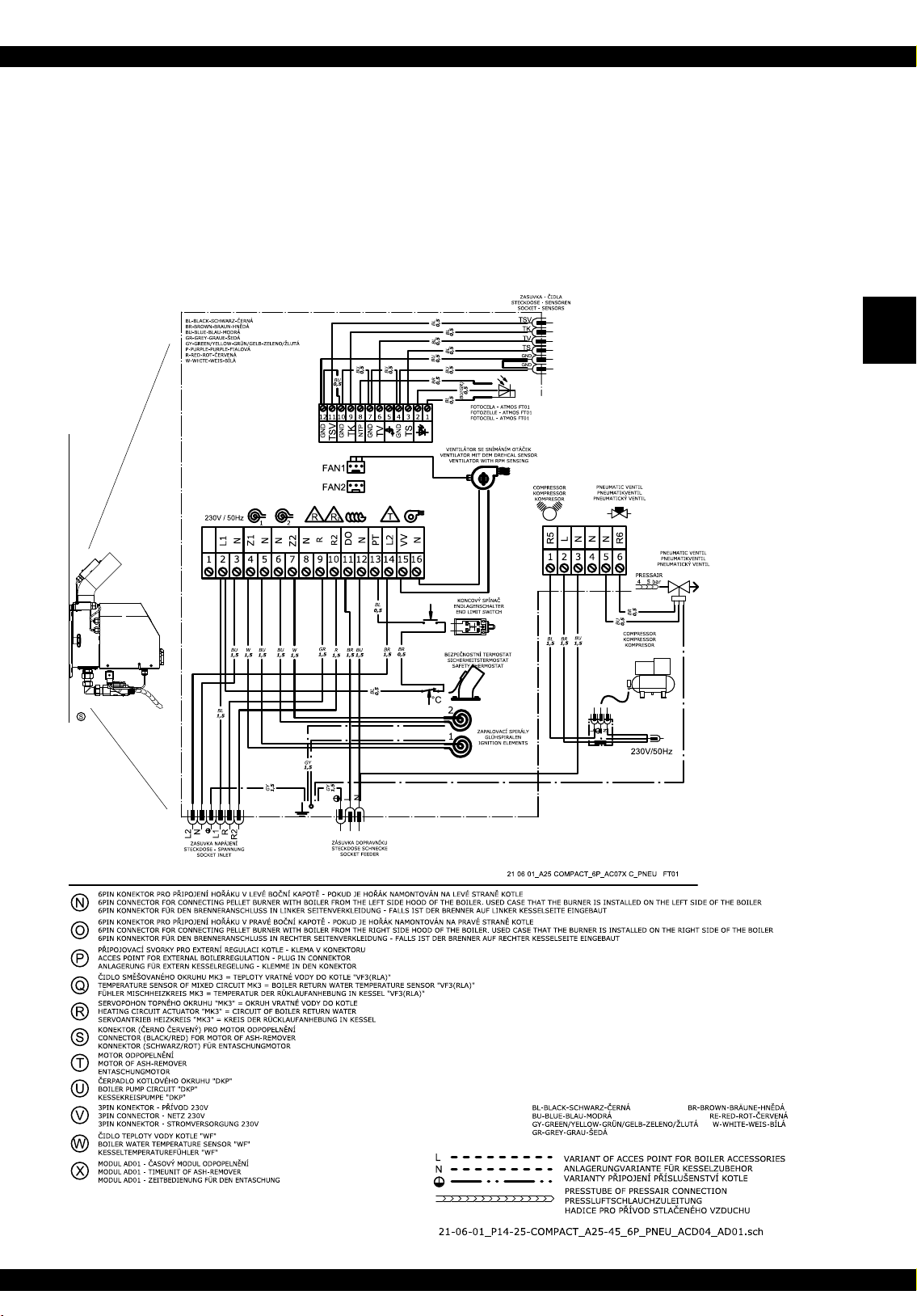
31. Electric wiring diagram of the P14 Compact, P21 Compact,
P25 Compact boilers - model with a 6-pin connector, with
ACD 04 controller and with pneumatic burner cleaning
EN
38-EN
www.atmos.cz
Page 39
Operation and maintenance manual - EN
EN
www.atmos.cz
EN-39
Page 40

Operation and maintenance manual - EN
32. Electric wiring diagram of the
DCxxSP(X), CxxSP, ACxxSP
boiler - model with a 6-pin connector on the boiler and
module AD03 - to control exhaust fan of the boiler and
pump in the boiler circuit
Old boilers version up to serial number 343500
SWITCH
EN
SCHALTER
HL.VYPÍNAČ
SNvyp
HLvyp
HNvyp
1245
PUMP THERMOSTAT
PUMPETERMOSTAT
TERMOSTAT NA ČERPADLO
SLvyp
TČ-1
TČ-C
t °C
A B
FUSE 6,3 A
POJISTKA 6.3 A
SICHERUNG 6.3 A
REGN (X6:3)
REGL (X6:4)
REGPE (X6:2)
LPUMP (X7:5)
poj-Cpoj-1
PE
TČ-2
C
DFE
L2OUT (X8:7)
LFAN IN (X7:6)
LFAN OUT (X7:7)
SAFETY THERMOSTAT
SICHERHEITSTERMOSTAT
BEZPEČNOSTNÍ TERM OSTAT
BT-N1
BT-L1
t °C
123456789101112
OPERATING THERMOSTAT
BETRIEB TERMOST AT
PROVOZNÍ TERMOSTAT
PE
PTC
BT-N2
BT-L2
SAFETY PUMP THERMOSTAT 95°C
SICHERHEITSPUMPETERMOSTAT 9 5°C
BEZPEČNOSTNÍ TERM. NA ČERPADLO 95°C
I
t °C
TČ95
TČ95
ALTERNATION SWITC H
FUNKTIONSUMSCHALT ER
PŘEPÍNAČ
PT1
vyp2-6
vyp2-4
vyp2-5
vyp2-2
t
WASTE GAS THERMOSTAT
RAUCHGAS TERMOSTAT
SPALINOVÝ TERMOST AT
PE
ST-2C
ST-1C
vyp2-1
vyp2-3
1245 6 3
KS
KS
END LIMIT DOOR SWITCH
WITH RESET BUTTON
ENDLAGENTÜRSCHALTER
KONCOVÝ SPÍNAČ DVÍŘEK
S RESET TLAČÍTKEM
L1
N
L2
R
R2
t °C
ST-21
ST-22
G
H
MIT RESET TASTE
A25-45 6PIN
KONEKTOR
ST-12
ST-11
N PE
L
R
LN PE LN
L1
R2
L2
L
N
J
N
BU
N
R2
RE
LC
R
GR
LD
L II
AD03
BR
LA
L I
BL
LB
KONDENZATOR 1 F
BLBLACKSCHWARZČERNÁ BRBROWNBRÄUNEHNĚD Á
BUBLUEBLAUMODRÁ REREDROTČERVENÁ
GYGREEN/YEL LOWGRÜN/GELBZELENO /ŽLUTÁ WWHI TEWEISBÍLÁ
WHEN USE ELECTRONIC REGULATI ON ACD01 AND PELLETBURNER A2545 MUST BE THESE CHANGES OF WIR ING:
BEI DER STEUERUNG DES KESSELBETRIEBES DER ELEKTRONISCHE REGELUNG ACD01 UND PELLETB RENNER A2545 MÜSSEN DIESE ÄNDERUNGEN MACHEN SEIN:
PŘI ZAPOJENÍ ELEKTRONICKÉ REG ULACE ACD01 A PELETOVÉHO HOŘÁKU A2545 PROVEĎTE TYTO ZMĚNY:
VARIANTS OF RESERVOIR POINTS "REG L,N,PE" (FERRULE/FASTON 6,3) FO R ELECTRONIC REGULATION
SPEISEKLEMMEVARIANTEN "REG L,N,PE" (ADERENDHÜLSE/FASTON 6,3) FÜR ELEKTRO NISCHE REGELUNG
A
VARIANTY NAPÁJECÍCH SVOREK "REG L,N,PE" (DUTINKA/FASTON 6,3) PRO ELEKTRONICKOU REGULACI
RESERVOIR POINT "L PUMP" OF BOILER PUMP TO THE ELECTRONIC REGULATION
SPEISEKLEMME "LPUMP" DER KESSELPUMPE FÜR DIE ELEKTRONISC HE REGELUNG
B
PŘIPOJOVACÍ SVORKA "LPUMP" KOTLOVÉHO ČERPADLA DO ELEKTRONI CKÉ REGULACE
RESERVOIR POINT "L FAN OUT" OF BOILER FAN TO THE ELECTRONIC REGULATION
SPEISEKLEMME "L FANO UT" DER KESSELGEBLÄSE FÜR DIE ELEKTRONI SCHE REGELUNG
C
PŘIPOJOVACÍ SVORKA "L FANOUT" KOTLOVÉHO VENTILÁTORU DO ELEKTRONICKÉ REGULACE
RESERVOIR POINT "L2OUT" OF BURNER TO THE ELECTRONIC REGULATI ON
SPEISEKLEMME "L2OUT" DER BRENNER FÜR DIE ELEKTRONISCHE REGELU NG
D
PŘIPOJOVACÍ SVORKA "L2OUT" HOŘÁKU DO ELEKTRONICKÉ REGULAC E
RESERVOIR POINT "L FAN IN" OF BOILER FAN TO THE ELECTRONIC REGULATION
SPEISEKLEMME "L FANI N" DER KESSELGEBLÄSE FÜR DIE ELEKT RONISCHE REGELUNG
E
PŘIPOJOVACÍ SVORKA "L FANIN" KOTLOVÉHO VENTILÁTORU D O ELEKTRONICKÉ REGULACE
WHEN ELECTRONIC REGULATION CONTROL BURNER AND FAN CONNECTORS "PTC" AND "PT1" MUST BE UNCONNECT
DEN KONNEKTOREN "PTC " UND "PT1" ABKLEMMEN BEI DER BRENNER BEDIENUNG UND KESSELGÄBLESEBEDIENUNG D ER ELEKTRONIC REGELUNG
F
KONEKTORY "PTC" A "PT1" ODPOJIT PŘI OVLÁDÁNÍ HOŘÁKU A VENTILÁTORU KO TLE ELEKTRONICKOU REGULACÍ
WHEN ELECTRONIC REGUL ATION CONTROL BOILER PUMP CONNECTORS "ST2C" AND "ST22" MUST BE UNCONNECT
DEN KONNEKTOREN "ST 2C" UND "ST22" ABKLEMMEN BEI DER K ESSELPUMPEBEDIENUNG DER ELEKTRONIC REGELU NG
G
KONEKTORY "ST2C" A "ST22" ODPOJIT PŘI OVLÁDÁNÍ ČERPADLA KOTLE ELEKTRONICKOU REGULAC Í
WHEN ELECTRONIC REGUL ATION CONTROL BOILER PUMP CONNECTORS "ST1C" AND "ST12" MUST BE UNCONNECT
DEN KONNEKTOREN "ST 1C" UND "ST12" ABKLEMMEN BEI DER K ESSELGÄBLESEBEDIENUNG DER ELEKTRONIC REG ELUNG
H
KONEKTORY "ST1C" A "ST12" ODPOJIT PŘI OVLÁDÁNÍ VENTILÁTORU KOTLE ELEKTRONICKOU REGULACÍ
WHEN ELECTRONIC REGULA TION CONTROL BOILER PUMP C ONNECTORS "TČ95" MUST BE UNCONNECT
DEN KONNEKTOREN "TČ9 5" ABKLEMMEN BEI DER KESSELPUMPEBEDIENUN G DER ELEKTRONIC REGELUNG
I
KONEKTORY "TČ95" ODPO JIT PŘI OVLÁDÁNÍ ČERPADLA KOTLE ELEKTRONICKOU REGULACÍ
NO WITH ACD01 MODUL AD03 FOR CONTROL BOILERFAN AND BOILERPUMP FROM BUR NER A25
NEIN MIT ACD01 MODUL AD03 FÜR BEDIENUNG KESSEL GEBLÄSE UND KESSELPUMPE BEI DEM BRENNER A2 5
J
NEPLATÍ S ACD01 MODUL AD03 K OVLÁDÁNÍ VENTILÁT ORU A ČERPADLA KOTLE HOŘÁKEM A25
µ
N
L
230V/50Hz
13-01-01_DCxxSP_A25-45_6P_AD03
40-EN
www.atmos.cz
Page 41

Operation and maintenance manual - EN
33. Wiring diagram connection of the boilers DCxxS(X),
CxxS(T), ACxxS, KCxxS, DCxxRS with exhaust fan, model
with 6-pin connector and two AD02 modules - to control
extraction fan of the boiler and pump in the boiler circuit
from burner control unit AC07X (R and R2)
EN
www.atmos.cz
EN-41
Page 42

Operation and maintenance manual - EN
34. Wiring diagram connection of DCxxS(X), CxxS(T), ACxxS,
KCxxS, DCxxRS boilers with exhaust fan, model with 6-pin
connector and two AD03 modules - to control extraction fan
of the boiler and pump in the boiler circuit from AC07X
burner control unit (R and R2) - 3/2017 modele
EN
42-EN
www.atmos.cz
Page 43

Operation and maintenance manual - EN
35.
Wiring diagram connection of
AC07X model with 6-pin connector
D10PX, PX10 boilers
with
-
EN
www.atmos.cz
EN-43
Page 44

Operation and maintenance manual - EN
36.
Wiring diagram connection of
D15PX, D20PX, D25PX,
EN
PX15, PX20, PX25 boilers
exhaust
fan of the boiler and pump in the boiler circuit
with exhaust fan
- to control
from AC07X burner control unit (R and R2)
44-EN
www.atmos.cz
Page 45
Operation and maintenance manual - EN
37. Commissioning
CAUTION - The system may only be put in operation if the burner is connected to the
boiler, the boiler to a chimney with sufficient draught via a flue gas duct and in the fuel bin
there is a sufficient quantity of pellets of the corresponding quality. Pellets made of soft
wood without bark, i.e. white pellets with the diameter of 6 to 8 mm and length of 5
to 25 mm are considered as high-quality pellets. These pellets do not cake. Burning of
dark pellets or pellets with bark that contain visible dark dots produces cake that must
be removed from the burner mouth once a day. Otherwise the combustion chamber
and the feeding hose from the conveyor will get clogged.
INFO - The pellets have to be stored in dry and clean containers (areas). When filling
the fuel bin, the pellets must not be contaminated by foreign objects that could cause a
blockage of the conveyor or have an impact on the burning process.
Requirements for the external conveyor and pellet bin at the first start of the burner:
• The worm conveyor must be positioned in the bin in such a way to be able to easily pick up
pellets. In the case of a fuel bin whose pellet level will be higher than 2 metres a roof will have
to be installed over the conveyor to prevent blocking of the conveyor. Blocking of the conveyor is
caused by dust in the pellets in combination with high pressure caused by the height of the pellet
level. ATMOS 250, 500 and 1000 l pellet bins do not require the installation of the roof.
EN
• The hose between the burner and conveyor must be tensioned, properly fixed and must have such
an inclination to enable trouble-free falling of pellets to the burner.
• The connector of the work conveyor must be plugged into the socket on the burner.
Procedure of drawing pellets to the conveyor
• Plug the connector of the external worm conveyor to a standard wall socket. As soon as the first
pellets get over the top point and start to fall to the burner via the elastic hose, plug the connector
of the external worm conveyor back into the socket on the burner.
Normal operation:
• On the control thermostat on the boiler panel set the required operation temperature of 80 - 90 °C
and turn on the switch of the burner located on the boiler panel and the main switch. For boilers
with a built-in burner in the upper doors reduce the combustion thermoregulator for heating.
The STARTup mechanism consists of the following steps:
At the start the worm conveyor and the ignition spiral are started (the fan on the burner is stopped).
•
• The worm conveyor will run for the time set by parameter T1, necessary for the delivery of the
amount for pellets for optimum ignition. After the delivery of the ignition amount of fuel the
worm conveyor will stop. The burner fan will be started at the ignition speed - parameter S2 as
well as the extraction fan (if the boiler is equipped with one and is set accordingly – reserve
R and parameter S6).
www.atmos.cz
EN-45
Page 46

Operation and maintenance manual - EN
• After the ignition of pellets the photocell will sense light, which will cause the ignition spiral to
switch off with a slight delay.
• The burner will pass over to the stage of perfect burning of fuel - set by parameter T7.
The OPERATION algorithm consists of the following steps:
• When the fuel burns perfectly, the burner will get to the stage of gradual increase of the power
to the nominal value - parameter T10.
EN
• After achieving the nominal power the burner works in the normal mode until the heating system
or the accumulation tank is heated to the required temperature. The power of the burner results
from the hourly quantity of pellets delivered by the worm conveyor to the combustion chamber.
The worm conveyor works in the intermittent mode set by parameters T4 and T6. Parameters
T4 and T6 are set in accordance with the instructions on page 50.
•
After setting the nominal power of the burner you must also set the amount of combustion air
necessary for complete burning of fuel. This setting is performed with the air flap on the burner
fan. The exact setting should be carried out by a trained person with the use of a flue gas
ana lyzer.
The burning out algorithm is designed as follows:
After the achievement of the set temperature at the boiler thermostat (e.g. 85 °C) or temperature
•
in the accumulation tank - temperature at the bottom sensor (TS), the electronic control unit of the
burner will switch off the external worm conveyor. Thanks to this, the pellets in the combustion
chamber will burn out. Optimal burning out of pellets in the combustion chamber is additionally
supported by the operation of the burner fan for a certain time - parameter T5. After subsequent
drop of the temperature of water in the boiler or discharge of the accumulation tank - temperature
at the top sensor (TV), the burner will be re-started in the same way as described in the text above.
If the accumulation tank is connected to a solar exchanger and activating functions for automatic
optimization (switching) of sensors, parameter S15 = 3, the burner may be turned off by sensor TK
instead of sensor TS.
The other algorithms are designed in the following way:
• If the first attempt for ignition with fuel supply fails, the burner will repeat the whole algorithm.
After the second unsuccessful attempt for ignition with fuel supply the burner will proceed to the
third attempt during which the fuel is not supplied any longer, but only the ignition spiral is active.
After this unsuccessful attempt the burner will be put out of operation as the system has probably
run out of pellets or a fault has occurred.
• In case of a short-term interruption of power supply to the burner, the burner will automatically
renew its operation after performing diagnostic checks, complete burning out of pellets and a
new start.
46-EN
INFO - This sequence has been set intentionally to ensure safe and trouble-free operation
of the burner.
www.atmos.cz
Page 47

Operation and maintenance manual - EN
38. Control and setting of the burner
Display and control panel
The electronic control unit of the burner is equipped with four keys for easy and intuitive control.
Enter - key for confirming a command and parameter or for entering a menu
Esc - key for return from a menu
Up arrow - key for browsing in the menus or for increasing the value of a parameter
Down arrow - key for browsing in the menus or for decreasing the value of a parameter
INFO - To open the Main Menu, press the Enter key.
EN
The PA RA ME TE R submenu will appear on the display. To change the basic permitted parameters
of the burner, confirm again - press the Enter key.
To switch off OFF (STOP) or to switch on ON (START) the burner or to get to the INFOR MATION,
PASSWORD
with the up or down arrow. Always confirm the ON (START) and OFF (STOP) command or
entering the particular submenu by pressing the Enter key. In the same way you can browse and
open individual menus and particular parameters in the menus. You can enter specific values or
numbers with the up ( + ) or down ( - ) arrow. Confirm the desired value with the Enter key. To
return one step backwards or completely to the main screen press the Esc key once or repeatedly.
Display with keys:
1. Information about the burner status
START – start-up stage
RUN – normal operation
STOP – burning-down stage or
stand-by mode
2. Temeperature TV (see page 74) – only if TS
and TV sensor are connected
3. Temeperature TS (see page 74) – only if TS
and TV sensor are connected
4. Symbol line – information about the
operation of particular devices of
the burner (see page 81)
or TESTING submenus, do not confirm the (PA RAM ET ER ) submenu, but continue
www.atmos.cz
EN-47
Page 48

MAIN menu
Operation and maintenance manual - EN
ON (START)
OFF (STOP)
PARAMETERS – This is a separate menu where individual parameters and functions can be set
EN
INFORMATION – This is a separate menu where you can view the current status of individual
PASSWORD – This is a very important parameter, designed only for service engineers. After entering
MODULE – shows actual connected additional module, e.g. AC07X-C.
PROFIL – shows actual set burner profile - A25, A25 pneu, A25 pneu Com, A25 GSP, A25 GSP pneu,
–
This is the command to switch on the burner. Confirm the switch-on command by
pressing the Enter key.
– This is the command to switch off the burner. Confirm the switch-off command by pressing
the Enter key.
depending on the type of the boiler and heating system and the authorization
level.
devices and elements on the A25 burner.
the required password the service engineer is allowed to change some parameters
depending on the authorization level.
A25PX, A25PX pneu, A45, A45 pneu, A85, A85 pneu, A85 pneu C
Basic authorization levels: User, service engineer (installer), manufacturer
Accessible parameters depending on authorization:
Customer: T1, T4, T6, S16, S17, S18, S19, Restart, Language
Service engineer:
Manufacturer: all
CAUTION - The customer is expressly prohibited to change parameters or functions
of the burner without consent of the manufacturer or service engineer although some
of them are not directly protected with a password. Otherwise the manufacturer reserves
the right to decline the guarantee due to an inexpert intervention into the burner.
Particular passwords are production secret of the ATMOS Company and the
service engineer (installer) is not authorized to provide them to anybody without the
manufacturer’s consent.
T1,T2, T4, T5, T6, T7, T8, T10, S1, S2, S3, S6, S11, S12, S13, S14, S15, S16,
S17, S18, S19, S24, S26, S27, S28, S29, S30, S31, S32, S33, S34, S35, S36,
S37, S38, S39, S40, S41, S42, S43, S44, S45, S48, S49, S50, S51, S52, S53,
S54, S55, S56, S57,
OffsetTS, OffsetTV, OffsetTK, OffsetTSV, Reset, Restart, Language
S58, S59, S60, S61, S62, S63, S64, S65, S66, S67, S68,
48-EN
www.atmos.cz
Page 49

Operation and maintenance manual - EN
INFO - After replacement of any ignition spiral the service engineer must enter the
password: 1234, which will reset the check algorithms for the ignition spirals. Without
entering of this password the ignition spirals will never be started (activated).
Passwords and their functions
Password Authorization / function
Service engineer
Manufacturer
EN
8118
1234
TESTING – This is a separate menu in which you can individually test individual elements of the
burner in case of unclear issues or faults.
CAUTION – During testing the burner is out of operation and therefore before the start of
testing let the burner properly burn out.
Switching off and on the fan speed control
Locking and unlocking all parameters
Reset of check algorithms for the ignition spirals
www.atmos.cz
EN-49
Page 50

Operation and maintenance manual - EN
PA R A METE R S me n u
• Device – Product type the electronic unit is designed for…(A25)
(A25, A25 pneu, A25 pneu Com, A25 GSP, A25 GSP pneu, A25PX, A25PX pneu,
A85, A85 pneu, A85 pneu C
)
• Parameter Т1 – Time for feeding the ignition amount of pellets …(100 s)
• Parameter Т2 – Maximum time for ignition of pellets (then a new attempt for ignition
EN
follows)…(10 min)
A45, A45 pneu,
• Parameter Т4
– Running time of the worm conveyor after a standstill interval – power control …(12 s)
• Parameter Т5 – Rundown time of the fan after the STOP command - for optimal burning out of
pellets in the combustion chamber …(15 min)
• Parameter Т6
– Standstill time of the worm conveyor after a running interval - power control …(8 s.)
• Parameter Т7 – Time to achieve complete burning of the ignition amount of fuel …(30 s)
• Parameter Т8 – Time of fixed start of the ignition spiral in case of insufficiently burned out
pellets in the combustion chamber after expiration of parameter T5 - only
valid for the first ignition attempt ... (6 min)
• Parameter Т10
if T10 = 0, the function is off.
– Time for gradual increase of the power of the burner to the nominal value …(10 min)
Setting the required power and combustion quality:
The required power is set with the use of parameters T4 and T6.
However, the actual power is also influenced by the diameter of pellets and angle of the conveyor.
Therefore, you should keep in mind that if after setting the burner you change the angle of the conveyor
or diameter of pellets, you will have to readjust the burner.
Adjust the combustion quality with the air flap of the fan in such a way that the flame tips should
always end 1 to 3 cm before the opposite wall. For boilers with burner built in the upper door
and the combustion length of 60 cm or greater, adjust the burner in such a way that the tip of
flame ends 10 to 15 cm before the opposite wall.
You should also know that the setting of the burner is different if the boiler is equipped with an
extraction fan and if the boiler does not have an extraction fan. The combustion should be precisely
tuned after 30 to 60 minutes of permanent operation, best with the use of a flue gas analyst. We
recommend you to adjust the burner in such a way that the surplus of O
range of 8 to 10 (12) % and the average CO content can be lower than 500 (250) mg/m
operation the flue gas temperature must never drop below 130 (110) °C and rise over 250 °C
(parameter S18).
INFO - As the burner is equipped with many functions (parameters), you should only set
the basic parameters that characterized the burner power - T4 and T6, the air flap.
50-EN
www.atmos.cz
in the flue gas can be in the
2
3
. During
Page 51

Operation and maintenance manual - EN
Recommended approximate setting of the burner with the use of DA1500, DA2000, DA2500,
DA3000 and DA4000 conveyors, for individual output values and pellets with the diameter of
6 mm and conveyor angle of 45°:
Boiler
output
ParameterT1ParameterT4ParameterT6Parameter
S3
Opening of the air
ap on the burner
fan of a boiler
with
an exhaust fan
Opening of the air
ap on the burner
fan of a boiler
without
an exhaust fan
10 – 12 kW 100 s 6 s 11 s 70 % 1/4 (12 mm) 1/2 (25 mm)
15 – 16 kW 100 s 8 s 10 s 100 % 1/4 (14 mm) 2/3 (37 mm)
20 – 24 kW 100 s 12 s 8 s 100 % 1/2 (27 mm) 3/4 (42 mm)
Recommended approximate setting of the burner with the use of DRA25 1,3 m and DRA25 1,7
m conveyors , for individual output values and pellets with the diameter of 6 mm and conveyor
angle of 65° (compact pellet tanks AZPU and AZPD):
Boiler
output
ParameterT1ParameterT4ParameterT6Parameter
S3
Opening of the air
ap on the burner
fan of a boiler
with
an exhaust fan
Opening of the air
ap on the burner
fan of a boiler
without
an exhaust fan
10 – 12 kW 60 s 3 s 15 s 70 % 1/4 (12 mm) 1/2 (25 mm)
EN
15 – 16 kW 60 s 3 s 13 s 100 % 1/4 (14 mm) 2/3 (37 mm)
20 – 24 kW 60 s 3 s 10 s 100 % 1/2 (27 mm) 3/4 (42 mm)
Burner settings for DxxPX and PXxx boilers follow instruction manual for this boilers.
INFO – If the boiler power is lower than 15 kW, switch off the extraction fan on the boiler
by removing the connector of the extraction fan from the boiler hood. This does not apply
for boilers with burner built in the upper doors and boilers DxxPX, PXxx where the
exhaust fan must always be running with the pellet burner. If necessary, if there is a
limited space in the boiler room, you can shorten the length of the conveyor (worm) or its
leg any time as desired, but the angle of the conveyor should never exceed 45°.
Minimum length of hose between the burner and the conveyor must be bigger than 20 cm.
Maximum hose length should not be more than 1 m.
• Parameter S1 – Allowed number of attempts for ignition with fuel supply… (2).
If parameter S1 is set to 4, the fuel will always be ignited with both the ignition elements at
the same time (Z1 + Z2) in 2 attempts for ignition with fuel supply.
CAUTION - Always after the last attempt for ignition with fuel supply given by parameter
S1, an attempt for ignition without fuel supply will follow to test the equipment. If the fuel
is not ignited after this attempt, the system will be put out of operation and the ALARM
START error message will appear.
www.atmos.cz
EN-51
Page 52

Operation and maintenance manual - EN
• Parameter S2 - fan speed at the START… (1 %) - do not change
CAUTION - 1 % = 700 rpm. If S2 = 0, the fan is off at the start.
• Parameter S3 – Fan speed during normal RUN… (100 %)
In normal circumstances we do not recommend you to reduce the fan speed as it influences
cooling and cleaning of inner parts of the burner. Only use the air flap to set the air quantity.
EN
• Parameter S4 – Fuel ignition control method …(1)
If:
a) S4 = 1…. Photocell sensing
• Parameter S6 – characterizes the first reserve R - additional output - function… (4)
The first reserve R is used mainly for controlling boiler exhaust fan (S6 = 4 )
CAUTION – In the standard setting when parameter S1 is set to 2, you can connect to
the reserve terminal
(approx. 566 VA).
In the setting when parameter S1 is set to 4, which means that at the start both the ignition
spirals are activated simultaneously, you can connect to the reserve terminal R, R2, R5 and
R6 an appliance with the maximum current of 0.29 A (approx. 67 VA).
If:
a) S6 = 1…. If any fault occurs in the burner and the burner is shut down, the reserve relay will
be closed and the reserve output will be energized. Thanks to this you can start a spare source
of energy for heating of the building as e.g. a gas, electric or oil boiler.
b) S6 = 2….. If any fault occurs in the burner and the burner is shut down, the reserve relay will
be opened and the reserve output will not be energized. Thanks to this a signal can be sent to
an electrically backed up AB01 ATMOS GSM module controller that will send information that
there is a system fault or the system is not energized. This is the opposite logic (to S6 = 1), which
means that during normal operation the reserve is energized.
c) S6 = 3…… The reserve function as the output function for the burner fan, when the reserve
output is closed, is energized always when the burner fan is running (fan mode only 100 % or
OFF). This function is applied if you want the boiler fan or extraction fan in the chimney to run
together with the burner fan. This function is designed for direct control of an fan directly from
the burner (e.g. DxxPX, PXxx).
R, R2, R5 and R6
an appliance with the maximum current of 2.46 A
52-EN
d) S6 = 4…… The reserve function as the reversed function of the output for the burner fan,
when the reserve output is off, is not energized always when the burner fan is running. This
function is always activated if you connect the A25 burner with the AS25 set containing the
AD02 or AD03 module, which in this case controls the extraction fan of the boiler. Install the
www.atmos.cz
Page 53

Operation and maintenance manual - EN
AD02 or AD03 module under the instrument hood of the boiler and connect it electrically
between the boiler terminal board and the extraction fan, see the wiring diagram.
This setting and connection with AD02 or AD03 module and special connector (jumper to main
switch) is standardly used for DCxxSP, CxxSP, ACxxSP boilers with the function for automatic
start after wood is burnt out activated (AUTOSTART – S34 = 1 or S34 = 2). Boiler exhaust
fan is running simultaneously with the pellet burner during the AUTOSTART function.
e) S6 = 5…… Reserve function as the output function for the Z1 ignition spiral when the reserve
copies the run of the ignition spiral.
f) S6 = 6….. Cleaning function of the combustion chamber or grill (flap). If the burner is in the
normal START, RUN and STOP mode, the output is not energized. The output is only energized
for the limited time T11, which continues immediately after the expiration of time T5 in the
STOP mode. It is not used with the A25 burner.
g) S6 = 7….. Reserve function as the output function for the external worm conveyor, when
the reserve copies the run of the external worm conveyor (cycles between time T4 and T6). The
reserve output work independently of the condition of the actual output for the external worm
conveyor. This means that if the standard output for the external conveyor gets damaged, the
reserve will work independently in accordance with the same program, and therefore it can be
used as a replacement for the damaged output.
EN
h) S6 = 8….. Reserve function as the output function for the external worm conveyor, when
the reserve copies the run of the external worm conveyor (cycles between time T4 and T6). The
reserve works in dependence on the status of the actual output for the external worm conveyor.
This means that if the output for the external conveyor gets damaged, the reserve will be switched
off automatically. This function is suitable in situations when you need to control another external
conveyor that supplies (feeds) pellets from a larger distance to the main conveyor from which the
pellets fall directly to the burner.
i) S6 = 9….. Reserve function as the output function for the external worm conveyor, when the
reserve copies the run of the external worm conveyor, but with the difference that it does not cycle, but
runs permanently both during the drawing of the ignition amount and during both the times T4
and T6. Thus, the other external conveyor runs continuously and works independently of the status
of the actual output for the external worm conveyor. This means that if the output to the main external
conveyor from which pellets directly fall to the burner gets damaged, the reserve will keep working
independently. This function can be used in cases when you need to control another external conveyor
that supplies (feeds) pellets from a larger distance to a pellet bin at the boiler from which the main
external conveyor draws pellets to supply them directly to the burner. Caution - the other external
conveyor must always be controlled with an additional level sensor (level meter) that will maintain the
level of pellets in the pellet bin at the boiler.
j) S6 = 10….. Reserve function as the output function for the external worm conveyor, when
the reserve copies the run of the external worm conveyor, but with the difference that it does not
cycle, but runs permanently both during the drawing of the ignition amount and during
both the times T4 and T6. Thus, the other external conveyor runs continuously, but it works in
dependence on the status of the actual output for the external worm conveyor. This means that if
www.atmos.cz
EN-53
Page 54

Operation and maintenance manual - EN
the output for the external conveyor from which pellets fall directly to the burner gets damaged,
the reserve will be switched off automatically. This function is convenient in cases when you
need to control another external conveyor that supplies (feeds) pellets from a larger distance to
a pellet bin at the boiler from which the main external conveyor draws pellets to supply them
directly to the burner. Caution - the other external conveyor must always be controlled with an
additional level sensor (level meter) that will maintain the level of pellets in the pellet bin at the
boiler. This is a similar function to S6 = 9, but with a higher degree of safety.
EN
k) S6 = 11….. Reserve function for controlling boiler exhaust fan for DCxxSP(X), CxxSP, ACxxSP
boiler types when the function for automatic start after wood is burnt out is activated. This function
ensures that boiler exhaust fan is running only during wood burning after the wood is burnt out.
When the burner is run on pellets, the boiler exhaust fan remains switched off. This function is
used if you do not need or want to use the boiler exhaust fan while the burner is running. Install
the AD02 module under the instrument hood of the boiler and connect it electrically between the
boiler terminal board and the extraction fan, see the wiring diagram.
WARNING – this is not a standard setting for DCxxSP(X), CxxSP, ACxxSP boilers with
the function of automatic start.
(AUTOSTART – S34 = 1 or S34 = 2) after wood is burnt out (standard setting is S6 = 4).
l) S6 = 12…..Reserve function for direct control of pump in the boiler circuit from the burner
regulation (boiler terminal board). This function controls the pump in the boiler circuit without
using AD02 or AD03 modules. This is applicable only for boilers that do not allow heating with
wood (not even in emergency situations). E.g. D14P, P14, D21P, P21, D25P, P25, D80P, P80,
DxxPX, PXxx. Pump output must be switched to reserve R on the boiler terminal board and the
TK sensor must be installed before this function can be activated. After activation, S37, S38, S39,
S40 temperature parameters must be checked and configured.
m) S6 = 13…..Reserve function is the reverse output function for controlling the pump in
the boiler circuit from the burner regulation (output cable from boiler with a connector – white
inside) via AD02 or AD03 modules. This function controls the pump in the boiler circuit using
AD02 or AD03 modules ranged into a set with pump thermostat installed into the boiler panel.
This method of pump controlling can be used for any ATMOS pellet boiler, and is therefore
recommended. AD02 or AD03 modules must be inserted and connected under the boiler hood
and the TK sensor must be installed before this function can be activated. After activation, S37,
S38, S39, S40 temperature parameters must be checked and configured.
54-EN
n) S6 = 14….. Reserve function for direct control of solar heating pump from the burner regulation
(boiler terminal board). This function control solar pump when automatic sensor switching function
is activated (S15=3), where the boiler is connected with accumulation tank equipped with solar
exchanger and collectors. The system requires TV, TK, TS and solar sensors to be connected to the
TSV solar panel. This function never uses AD02 or AD03 modules.
After activation, S26, S27, S28, S29, S30, S31, S32, S33 temperature parameters must be checked
and configured.
This function is specially designed for boilers: D14P, P14, D15P, P15, D20P, P20, D21P, P21,
D25P and P25
www.atmos.cz
Page 55

Operation and maintenance manual - EN
CAUTION - the direct controlling function of solar heating from pellet burner cannot be
used for
upper doors. This function also cannot be used when the pump is simultaneously controlled
in the boiler circuit from the burner regulation (TK sensor cannot be simultaneously in boiler
and accumulation tank)
o) S6 = 15….. Reserve function for the compressor control during the function for automatic
burner cleaning using compressed air. Power element designed for switching and powering the
compressor (e.g. contactor) must be connected between reserve output R and the compressor. This
function is connected with S6 (14), S41, S42, S43, S44, S45, S46, S47 parameter, which must be
checked and configured.
p) S6 = 16….. Reserve function for controlling el.fan during the function for automatic burner
cleaning using compressed air. This function is connected with S6 (14), S41, S42, S43, S44, S45,
S46, S47 parameter, which must be checked and configured.
Special function for turning on reserve output R according to the temperature of a concrete sensor:
DCxxSP(X)/(EP), CxxSP, ACxxSP
boilers and boilers with burner built into the
EN
a) e.g. function: TS>……. means that if the TS sensor temperature is higher then the set value in
S48 parameter – Temperature A, reserve output R will be activated
b) e.g. function: TS<……. means that if the TS sensor temperature is higher then the set value in
S48 parameter – Temperature A, reserve output R will be deactivated
c) e.g. function: TS, TV>……. means that if the TS and TV sensor temperature is higher at the
same time then the set value in S48 parameter – Temperature A and S50 – Temperature B, reserve
output R will be activated (Temperature A = first position (TS), Temperature B = second position
(Tv)).
d) e.g. function TS, TK<……. means that if the TS and TK sensor temperature is higher at the
same time then the set value in S48 parameter – Temperature A and S50 – Temperature B, reserve
output R will be deactivated (Temperature A = first position (TS), Temperature B = second position
(Tk)).
Individual functions:
(17) TS>
(18) TS<
(19) TV>
(20) TV<
(21) TK>
(22) TK<
(23) TSV>
(24) TSV<
(25) TS,TV>
(26) TS,TV<
(27) TS,TK>
(28) TS,TK<
(29) TS,TSV>
(30) TS,TSV<
(31) TV,TK>
(32) TV,TK<
(33) TV,TSV>
(34) TV,TSV<
(35) TK,TSV>
(36) TK,TSV<
www.atmos.cz
EN-55
Page 56

Operation and maintenance manual - EN
•
Parameter S7 – Function of the main external pellet conveyor – do not change in any case ... (1)
if:
a) S7 = 1….. Standard function when in the START mode the external conveyor supplies the ignition
amount of fuel during time T1, when it runs continuously.
In the RUN mode the external conveyor doses fuel by alternating times T4 (run) and T6 (standstill).
• Parameter S10 – Specifies the behaviour of the burner in case of a power supply failure or when
the boiler is activated with the main switch – do not change in any case… (1)
EN
a) S10 = 1… Function when after a power supply failure the electronic control unit tests the status
of the burner, evaluating with the use of the photocell or by means of the flue gas temperature that
the burner (boiler) is still burning. Subsequently, it first passes into the burning out mode T5
after which it proceeds to the new START immediately.
b) S10=2… Function when after a power supply failure the electronic control unit tests the status
of the burner, evaluating with the use of the photocell or by means of the flue gas temperature that
the burner (boiler) is still burning passes over directly to the normal RUN mode in accordance
with a certain algorithm.
CAUTION - Never use for the A25 burner - function for other types of devices (danger
of return burning)
• Parameter S11
– Photocell sensitivity – threshold for fuel ignition ……. (50 %) - do not change
• Parameter S12 – Photocell sensitivity for flame sensing - threshold for embers... (1 %) - do not change
• Parameter S13 – Fixed running time of the ignition spiral ……. (0 min) - do not change
Function of the ignition spiral when at every start the ignition spiral runs for a fixed time defined
by a direct value, independently on flame evaluation by the photocell or flue gas sensor. It is
designed for special applications and in the case of its activation the function of automatic flame
sensing from embers, characterized by parameter S12, is automatically switched off.
• Parameter S14 – characterizes the second reserve R2 - additional output - function … (0)
The second reserve R2 is used mainly for controlling the pump in boiler circuit (S14 = 13)
CAUTION – In the standard setting when parameter S1 is set to 2, you can connect to the
reserve
A (approx. 566 VA).
In the setting when parameter S1 is set to 4, which means that at the start both the ignition
spirals are activated simultaneously, you can connect to the reserve
terminal an applian¬ce with the maximum current of 0.29 A (approx. 67 VA).
R, R2, R5 and R6
reserve terminal an appliance with the maximum current of 2.46
R, R2, R5 and R6
56-EN
if:
a) S14 = 1…. If any fault occurs in the burner and the burner is shut down, the reserve relay will
be closed and the reserve output will be energized. Thanks to this you can start a spare source
of energy for heating of the building as e.g. a gas, electric or oil boiler.
www.atmos.cz
Page 57

Operation and maintenance manual - EN
b)
S14 = 2….. If any fault occurs in the burner and the burner is shut down, the reserve relay will
be opened and the reserve output will not be energized. Thanks to this a signal can be sent to an
electrically backed up AB01 ATMOS GSM module controller that will send information that there
is a system fault or the system is not energized. This is the opposite logic (to S14 = 1), which
means that during normal operation the reserve is energized.
c) S14 = 3…… The reserve function as the output function for the burner fan, when the
reserve output is closed, is energized always when the burner fan is running (fan mode only
100 % or OFF). This function is applied if you want the boiler fan or extraction fan in the chimney
to run together with the burner fan. This function is designed for direct control of an fan directly
from the burner (e.g. D80P, P80, DxxPX, PXxx).
d) S14 = 4…… The reserve function as the reversed function of the output for the burner fan,
when the reserve output is off, is not energized always when the burner fan is running. This
function is always activated if you connect the A25 burner with the AS25 set containing the
AD02 or AD03 module, which in this case controls the extraction fan of the boiler. Install the
AD02 or AD03 module under the instrument hood of the boiler and connect it electrically
between the boiler terminal board and the extraction fan, see the wiring diagram.
This setting and connection with AD02 or AD03 module and special connector (jumper to main
switch) is standardly used for DCxxSP(X), CxxSP, ACxxSP boilers with the function for
automatic start after wood is burnt out activated (AUTOSTART – S34 = 1 or S34 = 2). Boiler
exhaust fan is running simultaneously with the pellet burner during the AUTOSTART function.
EN
e) S14 = 5…… Reserve function as the output function for the Z1 ignition spiral when the reserve
copies the run of the ignition spiral.
f) S14 = 6….. Cleaning function of the combustion chamber or grill (flap). If the burner is in the
normal START, RUN and STOP mode, the output is not energized. The output is only energized
for the limited time T11, which continues immediately after the expiration of time T5 in the
STOP mode. It is not used with the A25 burner.
g) S14 = 7….. Reserve function as the output function for the external worm conveyor, when
the reserve copies the run of the external worm conveyor (cycles between time T4 and T6). The
reserve output work independently of the condition of the actual output for the external worm
conveyor. This means that if the standard output for the external conveyor gets damaged, the
reserve will work independently in accordance with the same program, and therefore it can be
used as a replacement for the damaged output.
h) S14 = 8….. Reserve function as the output function for the external worm conveyor, when
the reserve copies the run of the external worm conveyor (cycles between time T4 and T6). The
reserve works in dependence on the status of the actual output for the external worm conveyor.
This means that if the output for the external conveyor gets damaged, the reserve will be switched
off automatically. This function is suitable in situations when you need to control another external
conveyor that supplies (feeds) pellets from a larger distance to the main conveyor from which the
pellets fall directly to the burner.
i) S14 = 9….. Reserve function as the output function for the external worm conveyor, when the
reserve copies the run of the external worm conveyor, but with the difference that it does not cycle,
www.atmos.cz
EN-57
Page 58

EN
Operation and maintenance manual - EN
but runs permanently both during the drawing of the ignition amount and during both the
times T4 and T6. Thus, the other external conveyor runs continuously and works independently
of the status of the actual output for the external worm conveyor. This means that if the output
to the main external conveyor from which pellets directly fall to the burner gets damaged, the
reserve will keep working independently. This function can be used in cases when you need to
control another external conveyor that supplies (feeds) pellets from a larger distance to a pellet
bin at the boiler from which the main external conveyor draws pellets to supply them directly to
the burner. Caution - the other external conveyor must always be controlled with an additional
level sensor (level meter) that will maintain the level of pellets in the pellet bin at the boiler.
j) S14 = 10….. Reserve function as the output function for the external worm conveyor, when
the reserve copies the run of the external worm conveyor, but with the difference that it does not
cycle, but runs permanently both during the drawing of the ignition amount and during
both the times T4 and T6. Thus, the other external conveyor runs continuously, but it works in
dependence on the status of the actual output for the external worm conveyor. This means that if
the output for the external conveyor from which pellets fall directly to the burner gets damaged,
the reserve will be switched off automatically. This function is convenient in cases when you
need to control another external conveyor that supplies (feeds) pellets from a larger distance to
a pellet bin at the boiler from which the main external conveyor draws pellets to supply them
directly to the burner. Caution - the other external conveyor must always be controlled with an
additional level sensor (level meter) that will maintain the level of pellets in the pellet bin at the
boiler. This is a similar function to S6 = 9, but with a higher degree of safety.
k) S14 = 11….. Reserve function for controlling boiler exhaust fan for DCxxSP(X), CxxSP,
ACxxSP boiler types when the function for automatic start after wood is burnt out is activated.
This function ensures that boiler exhaust fan is running only during wood burning after the wood
is burnt out. When the burner is run on pellets, the boiler exhaust fan remains switched off. This
function is used if you do not need or want to use the boiler exhaust fan while the burner is running.
Install the AD02 module under the instrument hood of the boiler and connect it electrically between
the boiler terminal board and the extraction fan, see the wiring diagram.
WARNING – this is not a standard setting for DCxxSP(X), CxxSP, ACxxSP boilers with
the function of automatic start
(AUTOSTART – S34 = 1 or S34 = 2) after wood is burnt out (standard setting is S6 = 4).
l) S14 = 12…..Reserve function for direct control of pump in the boiler circuit from the burner
regulation (boiler terminal board). This function controls the pump in the boiler circuit without
using AD02 or AD03 modules. This is applicable only for boilers that do not allow heating with
wood (not even in emergency situations). E.g. D14P, P14, D21P, P21, D25P, P25, D80P, P80,
DxxPX, PXxx. Pump output must be switched to reserve R2 on the boiler terminal board and the
TK sensor must be installed before this function can be activated. After activation, S37, S38, S39,
S40 temperature parameters must be checked and configured.
m) S14 = 13…..Reserve function is the reverse output function for controlling the pump in
the boiler circuit from the burner regulation (output cable from boiler with a connector – white
inside) via AD02 or AD03 modules. This function controls the pump in the boiler circuit using
AD02 or AD03 modules ranged into a set with pump thermostat installed into the boiler panel.
58-EN
www.atmos.cz
Page 59

Operation and maintenance manual - EN
This method of pump controlling can be used for any ATMOS pellet boiler, and is therefore
recommended. AD02 or AD03 modules must be inserted and connected under the boiler hood
and the TK sensor must be installed before this function can be activated. After activation, S37,
S38, S39, S40 temperature parameters must be checked and configured.
S14 = 14….. Reserve function for direct control of solar heating pump from the burner regulation
n)
(boiler terminal board). This function control solar pump when automatic sensor switching function
is activated (S15 = 3), where the boiler is connected with accumulation tank equipped with solar
exchanger and collectors. The system requires TV, TK, TS and solar sensors to be connected to the
TSV solar panel. This function never uses AD02 or AD03 modules.
After activation, S26, S27, S28, S29, S30, S31, S32, S33 temperature parameters must be checked
and configured.
This function is specially designed for boilers: D14P, P14, D15P, P15, D20P, P20, D21P, P21,
D25P and P25
CAUTION - the direct controlling function of solar heating from pellet burner cannot be
used for
upper doors. This function also cannot be used when the pump is simultaneously controlled
in the boiler circuit from the burner regulation (TK sensor cannot be simultaneously in boiler
and accumulation tank)
DCxxSP(X)/(EP), CxxSP, ACxxSP
boilers and boilers with burner built into the
EN
o) S14 = 15….. Reserve function for the compressor control during the function for automatic
burner cleaning using compressed air. Power element designed for switching and powering the
compressor (e.g. contactor) must be connected between reserve output R2 and the compressor.
This function is connected with S6(14), S41, S42, S43, S44, S45, S46, S47 parameter, which must
be checked and configured.
p) S14 = 16….. Reserve function for controlling el.fan during the function for automatic burner
cleaning using compressed air. This function is connected with S6 (14), S41, S42, S43, S44, S45,
S46, S47 parameter, which must be checked and configured.
Special function for turning on reserve output R2 according to the temperature of a concrete sensor:
a) e.g. function: TS>… means that if the TS sensor temperature is higher then the set value in S52
parameter – Temperature C, reserve output R2 will be activated
b) e.g. function: TS<… means that if the TS sensor temperature is higher then the set value in
S52 parameter – Temperature C, reserve output R2 will be deactivated
c) e.g. function: TS, TV>… means that if the TS and TV sensor temperature is higher at the same
time then the set value in S52 parameter – Temperature C and S54 – Temperature D, reserve output
R2 will be activated (Temperature C = first position (TS), Temperature D = second position (Tv)).
d) e.g. function TS, TK<… means that if the TS and TK sensor temperature is higher at the same
time then the set value in S52 parameter – Temperature C and S54 – Temperature D, reserve output
R2 will be deactivated (Temperature C = first position (TS), Temperature D = second position
(Tk)).
www.atmos.cz
EN-59
Page 60

Individual functions:
Operation and maintenance manual - EN
(27) TS,TK>
(28) TS,TK<
(29) TS,TSV>
(30) TS,TSV<
(31) TV,TK>
(32) TV,TK<
(33) TV,TSV>
(34) TV,TSV<
(35) TK,TSV>
(36) TK,TSV<
EN
(17) TS>
(18) TS<
(19) TV>
(20) TV<
(21) TK>
(22) TK<
(23) TSV>
(24) TSV<
(25) TS,TV>
(26) TS,TV<
• Parameter S15 – Operation function of the burner by the two temperatures in the accumulation
tank …(1)
a) S15 = 1… The function is off, the burner works based on the thermoregulator on the boiler panel
b) S15 = 2 …. The function is activated and the pellet burner works based on the two temperatures
(sensors) in the accumulation tank – TV and TS (recommended tank volume: 500 to 1000 l).
The temperature of the bottom sensor (TS) is the temperature at which the burner is switched off
and the fuel burns out (parameter S16).
The temperature of the top sensor (TV) is the temperature at which the burner is switched on again
(parameter S17).
The burner screen displays the TV and TS temperatures.
c) S15 = 3 …. The function is activated and the pellet burner works based on the two temperatures
(sensors) in the accumulation tank – TV and TS (recommended tank volume: 500 to 1000 l).
The temperature of the top sensor (TV) is the temperature at which the burner is switched on again.
The temperature of the bottom sensor (TS or TK) is the temperature at which the burner is stopped.
Whether the burner is switched off based on the TS or TK sensor is decided by the temperature of
the solar panel (TSV) and the temperature in the lower part of the accumulation tank (TS), where a
solar exchange is built-in. If the solar panel can efficiently heat up water in the accumulation tank,
the burner is turned off based on the TK sensor, so that the tank can store energy from the sun.
If the energy delivered from the solar collector drops below a certain limit (temperature), the deactivation
logic of the burner is automatically switched back to be based on the TS sensor (S26 = 1).
However, it is possible to set that the switching may only occur after a certain period of time
(S29 = 2nd digit means the length of delay between switches, in hours). Another variant is to have
the burner work permanently based on the TV and TK temperatures (S26 = 0).
d) S15 = 4 …. The function is off and the burner works based on the TK temperature, protected
by the thermoregulators on the boiler panel. After this function is activated, we need to check and
possibly setup its temperature parameters S18 and S19.
CAUTION - if S15 = 2 not possible to set S6 = 14 a S14 = 14. Je-li S15 = 3 not possible
to set S6 = 11, S14 = 11, S6 = 12, S14 = 12, S6 = 13, S14 = 13. Je-li S15 = 1, S15 = 4 not
possible to set S14 = 14.
60-EN
www.atmos.cz
Page 61

Operation and maintenance manual - EN
• Parameter S16 - Temperature of the top sensor (TV) at which the burner is started….. (60 °C)
It is the minimum temperature of water that can be reasonably utilized in the heating system.
• Parameter S17 - The temperature of the bottom sensor ((TS, or TK for S15 = 3)) at which the
burner is stopped….. (75 °C)
It is the maximum temperature of water that corresponds to requirements of the heated building
and the designed heat exchangers in the system (radiators and floor heating).
CAUTION – Do not set this value too high to avoid disconnection of the safety thermostat on
the boiler. Always set the control thermostat on the boiler to the maximum value (95 °C). If
the control thermostat on the boiler intervenes before the burner is switched off by the signal of
the TS sensor in the bottom part of the accumulation tank, the system probably finds itself in the
state of hydraulic imbalance and you should check and adjust it. You can e.g. throttle the shortcut
in the boiler circuit or the return line from the heating system towards the accumulation tank.
• Parameter S18 – describes the required temperature of boiler TK, which the burner is switched
off at if S15 = 4… (85 °C)
EN
• Parameter S19
- difference between TK temperature (for re-starting the burner) for S15 = 4…(5 K)
• Parameter S24 – maximum flue gas temperature... (250 °C)
If you connect a flue gas temperature sensor (TS) to the burner and in a mode of the burner this
limit value is exceeded, a warning message will appear on the display. It will notify the operator of the
necessity to clean the heat exchanger of the boiler or the installer of the necessity to reduce the burner
power to avoid unnecessary wasting of fuel. The operation of the burner is not limited by this
message in any way and to clear the message you can just switch off and on the main switch on the
boiler.
•
Parameter S26
TK sensor, when S15 = 3. Connection of the boiler with a tank equipped with a solar exchanger… (1)
a) S26 = 0…. The burner permanently works based on the upper TV sensor (activation temperature)
and via the TK sensor (deactivation temperature). The lower part of the tank permanently has
enough room for energy from the solar collector (TS sensor)
b) S26=1… the burner permanently works based on the upper TV sensor (activation temperature)
and the configured logic automatically takes care of switching between the middle TK sensor and
lower TS sensor. Whether the burner is deactivated based on TS or TK is decided based on the
temperature on the solar panel (TSV) and the temperature on the lower part of the accumulation
tank (TS), where the solar exchanger is located. If the solar panel can efficiently heat up water in
the accumulation tank, the burner is turned off based on the TK sensor, so that the tank can store
energy from the sun.
– is the function for defining the logic of deactivating the burner based on the TS or
• Parameter S17 - activation difference of function S26 = 1… (10 K)
If the temperature on the solar panel (TSV) exceeds the temperature in the lower part of the tank
by the activation difference, the boiler deactivation function will be switched from the bottom TS
sensor to the middle TK sensor.
If a function for solar panel pump control is activated directly from the boiler regulation (S6 = 14
or S14=4), the same logic will be used to activate the solar pump.
www.atmos.cz
EN-61
Page 62

Operation and maintenance manual - EN
• Parameter S28 – deactivation difference of function S26 = 1… (3 K)
If the temperature on the solar panel (TSV) exceeds the temperature in the lower part of the tank
by the deactivation difference, the boiler deactivation function will be switched from the middle
TK sensor to the bottom TS sensor.
If a function for solar panel pump control is activated directly from the boiler regulation (S6 = 14
or S14 = 4), the same logic will be used to activate the solar pump.
• Parameter S29 – is the function for delaying the automatic switching from the TK sensor back to
EN
the TS sensor for controlling the burner based on two temperatures (sensors, S15 = 3)... (0 hours)
This function will cause the function for deactivating the burner to be switched from the middle
TK sensor to the bottom TS sensor after the time listed in parameter S29 passes, if the temperature
on the solar panel TSV is lower or greater only by the deactivation difference (Parameter S28) than
the temperature in the lower part of the tank where the solar exchange is located.
The set value means the number of hours, e.g.: S29 = 2 means a switch delay of 2 hours.
• Parameter S30 – is the function of the minimal operating time of the solar pump when the
conditions for its activation and then deactivation are met (function S15 = 3)… (3 min )
The set value means the number of minutes, e.g.: S30 = 3 means 3 minutes
• Parameter S31 – characterizes the required temperature TS in the lower part of the accumulation
tank where the solar exchanger is located, during the function of charging the accumulation tank
by the solar collector. (function S15 = 3)… (75 °C)
Once it is reached, the solar pump will be turned off.
• Parameter S32 – characterizes the maximum temperature TV in the accumulation tank during the
function of charging the accumulation tank by the solar collector (function S15 = 3)… (100 °C)
The solar pump will be turned off if it is exceeded.
• Parameter S33 – characterizes the maximum temperature TSV of the solar collector, for which
the solar pump will still remain in operation (function S15 = 3) …(115 °C)
The solar pump will be turned off if it is exceeded.
• Parameter S34 – is the function of automatically starting the pellet burner (AUTOSTART) after
the wood burns out. The function is specially created for DCxxSP(X)/(EP), CxxS, ACxxSP burners,
however it may also be used for two separate boilers …. (0)
a) S34 = 0…. The automatic start function is off
b) S34 = 1…. The automatic start function is on. The pellet burner will be turned on when the
temperature of exhausts TSV drops below the set value (S36 = 80), e.g. below 80 °C
c) S34 = 2…. The automatic start function is on. The pellet burner will be turned on when two
conditions are met:
- the temperature of the boiler TK drops below the set value (S35 = 75), e.g. below 75 °C
- the temperature of exhausts TSV drops below the set value (S36 = 80), e.g. below 80 °C
62-EN
www.atmos.cz
Page 63

Operation and maintenance manual - EN
If the function (parameter S34) is turned on in the boiler, the following practice is used for
boilers DCxxSP(X)/(EP), CxxSP, ACxxSP:
If the boiler is burning out but the wood container still contains enough wood, we may directly
switch the boiler switch from wood to pellets.
The pellet burner will perform a DIAGNOSTIC which will be used to ascertain the current status
of the boiler (temperature of exhausts, temperature of the boiler, temperature in the accumulation
tank)
If the conditions for immediate start of the burner are not met (see above), the burner will remain
on standby, where the flue exhaust fan will remain in operation (if set) so that the wood can
properly finish burning (S6 = 4). AUTOSTART will start flashing on the burner screen.
If the AUTOSTART sign flashes slowly, the conditions set by the function (S34 = 1 or S34 = 2)
are not met.
If the AUTOSTART sign flashes quickly, the previous conditions are met, but the conditions set
by function (S15 = 2) are not, which means that the temperature on the accumulation tank did not
drop below the value set by S16 or the regulation thermoregulator on the boiler is not activated, i.e.
the end switch is not pressed (a star is not displayed on the boiler screen near the thermoregulator
symbol)
If all the conditions are met, the burner will start automatically.
EN
INFO – In case of an electric outage, the burner will perform a DIAGNOSTIC and, if all
conditions are met, will burn out and return to normal operation. Otherwise it will await the
fulfillment of previous conditions (drop of exhaust and water temperature).
If we want to use wood to heat up the boiler, it suffices to place the switch on the wood
position. However, it is better to first keep the switch on the „0“ position for 10 - 15 minutes
so that the burner can properly burn out. This is an ideal time to prepare the fuel for stoking.
WARNING – DCxxSP(X)/(EP), CxxSP, ACxxSP boilers do not allow you to control the
solar heating function directly from the pellet burner. Additionally the TK and TSV sensors
are used for measuring the temperature of the boiler and exhausts during this function.
• Parameter S35 – characterizes the limit (max.) temperature of the boiler TK, during which the
burner will automatically start during the AUTOSTART function (S34 = 2)… (75 °C)
• Parameter S36 – characterizes the limit (max.) temperature of the exhausts TSV, during which the
burner will automatically start during the AUTOSTART function (S34 = 2)… (80 °C)
WARNING – after placing the exhaust sensor TSV on a side of the burner flue pipe, the
TSV temperature is not the exact temperature of the exhausts but the difference temperature
for the automatic start function. If we want to place the exhaust sensor directly on or into the
flue pipe to measure the exhaust temperature precisely, it is necessary to always use a sensor
with a higher heat resistance of up to 400 °C.
• Parameter S37 – characterizes the requires temperature of the boiler TK during which the pump in
the boiler circuit will be activated. This will only occur if the required temperature is reached and
the boiler is in OPERATION or burn-out mode (S14=13 with modules AD02 or AD03)… (75 °C)
It is also necessary to re-check or set parameters S38, S39, S40
www.atmos.cz
EN-63
Page 64

Operation and maintenance manual - EN
• Parameter S38 – deactivation difference for parameter S37, of the pump in the boiler circuit
(S14 = 13 or S6 = 13)… (2 K)
If the temperature of the boiler TK drops by more than the deactivation difference S38, the pump
in the boiler circuit will be turned off in the OPERATION or STOP (burn-out) modes.
• Parameter S39 – characterizes the emergency temperature of the boiler TK, during which the
pump in the boiler circuit will be activated (S14 = 13 with modules AD02 or AD03)… (93 °C)
Activation will be carried out regardless of special functions of the burner (function S40). The
EN
function works based on the deactivation difference specified in parameter S38.
• Parameter S40 – is the function for after-running of the pump in the boiler circuit used based on
boiler type (S14 = 13, S6 = 13)… (0)
a) S40 = 0…. The automatic deactivation function for the pump in the the boiler circuit after the
pellet burner burns out is off (after the time specified in parameter T5 runs out). The pump will
be switched off after the temperature of the boiler TK drops (S38, S39). Designated for ceramic
boilers with a large momentum (with the option of stoking with wood).
b) S40 = 1... The automatic deactivation function for the pump in the boiler circuit after the pellet
burner burns out is on. The pump will be switched off immediately after the burner burns out, after
the time specified in parameter T5 runs out. The function designated by parameter S39 is active.
Designated for boilers with minimal momentum without ceramics (D14P, P14, D21P, P21, D25P, P25).
• Parameter S41 – is the function for automatic burner cleaning with compressed air after a specific
number of working cycles (burn-out). The function assumes use of both reserve outputs (S6 = 16,
S14 = 15 (S67 = 15, S68 = 16 in case of AC07X-C module)) – non-standard function (4)
a) S41 = 1 - 9… function when the cleaning of the burner will be performed only once after ru-
nning a given number of cycles (1, 2, 3, 4, 5, 6, 7, 8, 9 - number of cycles)
b) S41 = 11 - 19… function when the cleaning of the burner will be performed always twice after
running a given number of cycles (11 = 1, 12 = 2, 13 = 3, 14 = 4, 15 = 5, 16 = 6, 17 = 7, 18 = 8,
19 = 9 - number of cycles) (from 1.4.2013)
If the parameter S41 = 0 or 10, the function is turned off.
• Parameter S42 – is the function for automatic burner cleaning with compressed air after a specific
period of operation time has passed (in one cycle). Once the subsequent working cycle has ended
(burn-out), the burner tubing is cleaned. The function assumes use of both reserve outputs (S6 = 16,
S14 = 15 (S67 = 15, S68 = 16 in case of AC07X-C module)) – non-standard function… (6 hours)
The value set is the actual time in hours.
• Parameter S43 – is the function for automatic burner cleaning with compressed air after a specific
period of operation time has passed. Once the set time has bassed, the burner immediately burns
out (AUTOSTOP), it is cleaned and once again run. If required at all requirements for START are
met. (regardless of S41 and S42 parameters). The function assumes use of both reserve outputs
(S6 = 16, S14 = 15 (S67 = 15, S68 = 16 in case of AC07X-C module)) – non-standard function…
(12 hours)
This is the sum of operating hours of all completed cycles.
The value set is the actual time in hours.
64-EN
www.atmos.cz
Page 65

Operation and maintenance manual - EN
• Parameter S44 – is the compressor function for automatic cleaning of the burner by compressed
air, which determines the duration of compressor operation used for preparing a sufficient amount
of compressed air (pressure function S6 = 16) - nonstandard function… (2 min)
The set value represents the actual time in minutes.
• Parameter S45 – is the electric valve function for automatic cleaning of the burner by compressed
air, which determines how long the el. valve is open to perfectly clean the combustion chamber of
the burner (S14 = 15) - nonstandard function… (1 s)
The set value represents the actual time in seconds.
• Parameter S46 – is the burner fan function which sets the type of used fan with rotation scanning.
Number of impulses.… (
12-EBM
)
• Parameter S47 – is the function of fan 2 which sets the type of used fan with rotation scanning.
Number of impulses – do not change the factory setting… (0)
a) S47 = 12 - EBM..... radial blower of the burner
b) S47 = 4 - ATAS..... exhaust blower of the boiler
c) S47 = 0..... second method for switching off the blower 2 speed sensing
• Parameter S48 – characterizes temperature TEMPERATURE A in the applications of function
S6 = 17 to 36… (75 °C)
This is a free function for the reserve output R (R5) on the first position (Temperature A = first
position in function S6 = 17 to 36 (S67 = 17 až 36)).
• Parameter S49 – characterizes the activation or deactivation difference for TEMPERATURE A
in the applications of function S6 = 17 to 36… (5K)
This is the difference for the free function of reserve output R (R5) on the first position (difference
for Temperature A = difference for the first position in the function S6 = 17 to 36 (S67 = 17 až 36)).
• Parameter S50 – characterizes TEMPERATURE B in the applications of function S6 = 25 to
36...….(75 °C)
This is a free function for the reserve output R (R5) on the first position (Temperature B = second
position in function S6 = 25 to 36 (S67 = 17 až 36)).
EN
• Parameter S51 – characterizes the activation or deactivation difference for TEMPERATURE B
in the applications of function S6 = 25 to 36… (5K)
This is the difference for the free function of reserve output R (R5) on the first position (difference
for Temperature B = difference for the first position in the function S6 = 25 to 36 (S67 = 17 až 36)).
• Parameter S52 – characterizes TEMPERATURE C in the applications of function S6 = 25 to
36...… (75 °C)
This is a free function for the reserve output R2 (R6) on the first position (Temperature C = second
position in function S14 = 17 to 36 (S67 = 17 až 36)).
• Parameter S53 – characterizes the activation or deactivation difference for TEMPERATURE C
in the applications of function S14 = 17 to 36… (5K)
This is the difference for the free function of reserve output R2 (R6) on the second position
(difference for Temperature C = difference for the second position in the function S14 = 17 to 36
(S68 = 17 až 36)).
www.atmos.cz
EN-65
Page 66

Operation and maintenance manual - EN
• Parameter S54 – characterizes TEMPERATURE D in the applications of function S14 = 25 to
36…. (75 °C)
This is a free function for the reserve output R2 (R6) on the first position (Temperature D = second
position in function S14 = 25 to 36 (S68 = 17 až 36)).
• Parameter S55 – characterizes the activation or deactivation difference for TEMPERATURE D
in the applications of function S14 = 25 to 36… (5K)
This is the difference for the free function of reserve output R2 (R6) on the second position
EN
(difference for Temperature D = difference for the second position in the function S14 = 25 to 36
(S68 = 17 až 36)).
• Parameter S56 – characterizes control of functioning (speed sensing) of the exhaust blower of
the boiler (blower 2); setting may be different according to use – must never be changed...... (0)
a) S56 = 0 ..... control of the exhaust blower of the boiler turned off
a) S56 = 1 ..... control of the exhaust blower of the boiler turned on
If S56 = 1, parameters S47 and S57 are activated (visualized).
• Parameter S57 – characterizes minimum speed of the blower 2 ....... (1,000 rpm) – must never
be changed
adjustable range ..... 1,000 – 3,200 rpm
It is a function of the control of proper functioning of the exhaust blower of the boiler.
When the blower is running at the speed lower than set, “ALARM VENT 2” is declared.
This function is not used standardly.
• Parameter S58 – characterizes the amount of compressed air for the first pre-cleaningoftheburner
when installing pneumatic cleaning the burner. This is the time at which the partial fillingcompressor
air tank for pre-cleaning of the burner ... (6 s) - standardly do not change
Adjustable range...OFF, 1 - 120 s.
• Parameter S59 – characterizes the amount of compressed air for the second pre-cleaning of the
burner when installing pneumatic burner cleaning. This is the time at which the partial filling
compressor air tank for pre-cleaning of the burner... (OFF) - standardly do not change
Adjustable range...OFF, 1 - 120 s.
• Parameter S60 – characterizes the amount of compressed air for the third pre-cleaning of the
burner when installing pneumatic burner cleaning. This is the time at which the partial filling
compressor air tank for pre-cleaning of the burner... (OFF) - standardly do not change
Adjustable range...OFF, 1 - 120 s.
• Parameter S61 – characterizes the function for control of the boiler exhaust fan from the outlet for
the burner discharge fan via the AD04 module. The function is intended for models DCxxSP(X),
CxxSP, ACxxSP without flap with actuator fitted with the pneumatic burner cleaning options and the
activated function for automatic start of the burner following wood burnout - AUTOSTART... (0)
a) S61 = 0....... function OFF
b) S61 = 1....... function ON (for for profile A25 pneu)
Never activate this function for boilers DCxxGSP and DCxxSP(X), CxxSP, ACxxSP (Model since
2018 equipped with flap with actuator).
66-EN
www.atmos.cz
Page 67

Operation and maintenance manual - EN
• Parameter S62 – characterizes the function for control of the air valve (flap) with actuator (servo
drive) located in the pellet burner. This valve is operated from the outlet of the burner discharge fan
via the AD04 module integrated in the burner (from serial production - default configuration). The
function is intended for models DCxxGSP, DCxxSP(X), CxxSP, ACxxSP (Model since 2018)... (1)
a) S62 = 0....... funkce OFF (for burners without flap with actuator)
b) S62 = 1....... function ON (for burners with flap with actuator - for models DCxxGSP and
DCxxSP(X), CxxSP, ACxxSP (Model since 2018))
(Burners equipped with internal flap with actuator with AD04 module and the third (additional)
2-pins connector.)
• Parameter S63 – characterizes the function of start delay of the pellet burner (AUTOSTART),
with function of automatic burner start after burnout of the wood. Start delay of the pellet burner
we use in case, that the operator wants to switch the selector switch from the position - wood
to the position - pellets immediately after firing up without waitng till the boiler ran at nominal
output (TSV and TK temperatures not reached). This will always delay the start of the burner
60/120/180/240 minutes. When activating this function the display of the burner shows the time
remaining until the automatic start of the pellet burner (cold condition) or until the change to the
normal function of automatic start characterized with the parameter S34.
In case of that the operation waste gas temperature will be reached (parameter S36 = TSV + 20 K) ends
the countdown of the automatic start and the burner goes directly to normal auto start (parameter S34).
EN
a) S63 = OFF... function switched off - factory stetting
b) S63 = 1... start delay of 1 hour (60 min) - recommended setting
c) S63 = 2... start delay of 2 hour (120 min)
(Setting possibility S63 = OFF, 1 (60 min), 2 (120 min), 3 (180 min), 4 (240 min))
This special function is active in the program version 38 and newer.
INFO - when putting burner into operation with activated function S63 = 1 (or 2, 3, 4) the
plumber may once enter the code 1111 and to skip from AUTOSTART directly to the burner
START (TSV and TK below than defined).
• Parameter S64 - characterizes the temperature of flue gas inside the heat exchanger of the boiler.
It serves to diagnoses the absense of pellets in the boiler tank or shows low output of the boiler. It
is not temperature of flue gas. Function is only for DxxPX (PXxx) boilers, burner profile A25PX.
Do not change… (130 °C)
• Parameter S65 - characterizes start up time of the burner in OPERATION mode during which has
to be reached minimal waste gas temperature in the heat exchanger of the boiler set by parameter
S64.
If in this time the boiler does not reach temperature the display shows ALARM SETTINGS –
REFILL PELLETS. In such case check the set output in parameters T4 and T6 and increase it.
In case of low pellets level in the tank fill up the fuel. Function is only for DxxPX (PXxx) boilers,
burner profile A25PX. Do not change… (120 min)
www.atmos.cz
EN-67
Page 68

Operation and maintenance manual - EN
• Parameter S66 - characterizes run-out time of the burner in OPERATION mode during which the
burner stays in operation when waste gas temperature in the heat exchanger of the boiler descend
under the temperature characterized by the parameter S64.
After the time characterized by the paramater S66 is display ALARM PELLETS – REFILL
PELLETS. In this case check the pellet tank and fill up the fuel.
DxxPX (PXxx) boilers are designed that after fuel refill is neccesary only to turn off and on the
main swich on the boiler. So it is not neccesary fill up the pellets into the conveyor after showen
ALARM PELLETS – REFILL PELLETS.
Function is only for DxxPX (PXxx) boilers, burner profile A25PX. Do not change… (30 min)
EN
• Parameter S67 - characterizes function of R5 reserve output similar with S6 and S14 parameters
with instaled AC07X-C additional module. Primary is this reserve used to control air pump for
pellet burner pneumatic ash cleaning system S67 = 15.
Function is only for DxxPX (PXxx) boilers
burner profile A25PX (A25PX pneu)....... (0)
if:
or burners equiped with additional AC07X-C module
,
a) S67 = 1…. If any fault occurs in the burner and the burner is shut down, the reserve relay will
be closed and the reserve output will be energized. Thanks to this you can start a spare source
of energy for heating of the building as e.g. a gas, electric or oil boiler.
b) S67 = 2….. If any fault occurs in the burner and the burner is shut down, the reserve relay will
be opened and the reserve output will not be energized. Thanks to this a signal can be sent to
an electrically backed up AB01 ATMOS GSM module controller that will send information that
there is a system fault or the system is not energized. This is the opposite logic (to S6 = 1), which
means that during normal operation the reserve is energized.
c) S67 = 4…… The reserve function as the reversed function of the output for the burner fan,
when the reserve output is off, is not energized always when the burner fan is running. This
function is always activated if you connect the A25 burner with the AS25 set containing the
AD02 or AD03 module, which in this case controls the extraction fan of the boiler. Install the
AD02 or AD03 module under the instrument hood of the boiler and connect it electrically
between the boiler terminal board and the extraction fan, see the wiring diagram.
This setting and connection with AD02 or AD03 module and special connector (jumper to main
switch) is standardly used for DCxxSP boilers with the function for automatic start after
wood is burnt out activated (AUTOSTART – S34 = 1 or S34 = 2). Boiler exhaust fan is
running simultaneously with the pellet burner during the AUTOSTART function.
68-EN
d S67 = 7….. Reserve function as the output function for the external worm conveyor, when
the reserve copies the run of the external worm conveyor (cycles between time T4 and T6). The
reserve output work independently of the condition of the actual output for the external worm
conveyor. This means that if the standard output for the external conveyor gets damaged, the
reserve will work independently in accordance with the same program, and therefore it can be
used as a replacement for the damaged output.
e) S67 = 8….. Reserve function as the output function for the external worm conveyor, when
the reserve copies the run of the external worm conveyor (cycles between time T4 and T6). The
www.atmos.cz
Page 69

Operation and maintenance manual - EN
reserve works in dependence on the status of the actual output for the external worm conveyor.
This means that if the output for the external conveyor gets damaged, the reserve will be switched
off automatically. This function is suitable in situations when you need to control another external
conveyor that supplies (feeds) pellets from a larger distance to the main conveyor from which the
pellets fall directly to the burner.
f) S67 = 15….. Reserve function for the compressor control during the function for automatic
burner cleaning using compressed air. Power element designed for switching and powering the
compressor (e.g. contactor) must be connected between reserve output R5 and the compressor.
This function is connected with S68, S41, S42, S43, S44, S45, S46, S47 parameter, which must be
checked and configured.
g) S67 = 16….. Reserve function for controlling el.fan during the function for automatic burner
cleaning using compressed air. This function is connected with S68, S41, S42, S43, S44, S45, S46,
S47 parameter, which must be checked and configured.
Special function for turning on reserve output R5 according to the temperature of a concrete sensor:
EN
a) e.g. function: TS>……. means that if the TS sensor temperature is higher then the set value in
S48 parameter – Temperature A, reserve output R5 will be activated
b) e.g. function: TS<……. means that if the TS sensor temperature is higher then the set value in
S48 parameter – Temperature A, reserve output R5 will be deactivated
c) e.g. function: TS,TV>……. means that if the TS and TV sensor temperature is higher at the
same time then the set value in S48 parameter – Temperature A and S50 – Temperature B, reserve
output R5 will be activated (Temperature A = first position (TS), Temperature B = second position
(Tv)).
d) e.g. function TS,TK<……. means that if the TS and TK sensor temperature is higher at the
same time then the set value in S48 parameter – Temperature A and S50 – Temperature B, reserve
output R5 will be deactivated (Temperature A = first position (TS), Temperature B = second
position (Tk)).
Individual functions:
(17) TS>
(18) TS<
(19) TV>
(20) TV<
(21) TK>
(22) TK<
(23) TSV>
(24) TSV<
(25) TS,TV>
(26) TS,TV<
(27) TS,TK>
(28) TS,TK<
(29) TS,TSV>
(30) TS,TSV<
(31) TV,TK>
(32) TV,TK<
(33) TV,TSV>
(34) TV,TSV<
(35) TK,TSV>
(36) TK,TSV<
www.atmos.cz
EN-69
Page 70

Operation and maintenance manual - EN
• Parameter S68 - characterizes function of R6 reserve output similar with S6 and S14 parameters
with instaled AC07X-C additional module. Primary is this reserve used to control electic valve for
pellet burner pneumatic ash cleaning system S68 = 16.
Function is only for DxxPX (PXxx) boilers
burner profile A25PX (A25PX pneu)....... (0)
if:
or burners equiped with additional AC07X-C module
,
EN
a) S68 = 1…. If any fault occurs in the burner and the burner is shut down, the reserve relay will
be closed and the reserve output will be energized. Thanks to this you can start a spare source
of energy for heating of the building as e.g. a gas, electric or oil boiler.
b) S68 = 2….. If any fault occurs in the burner and the burner is shut down, the reserve relay will
be opened and the reserve output will not be energized. Thanks to this a signal can be sent to an
electrically backed up AB01 ATMOS GSM module controller that will send information that there
is a system fault or the system is not energized. This is the opposite logic (to S14 = 1), which
means that during normal operation the reserve is energized.
c) S68 = 3…… The reserve function as the output function for the burner fan, when the
reserve output is closed, is energized always when the burner fan is running (fan mode only
100 % or OFF). This function is applied if you want the boiler fan or extraction fan in the chimney
to run together with the burner fan. This function is designed for direct control of an fan directly
from the burner (e.g. DxxPX, PXxx).
d) S68 = 9… Reserve function as the output function for the external worm conveyor, when the
reserve copies the run of the external worm conveyor, but with the difference that it does not cycle,
but runs permanently both during the drawing of the ignition amount and during both the
times T4 and T6. Thus, the other external conveyor runs continuously and works independently
of the status of the actual output for the external worm conveyor. This means that if the output to
the main external conveyor from which pellets directly fall to the burner gets damaged, the reserve
will keep working independently. This function can be used in cases when you need to control
another external conveyor that supplies (feeds) pellets from a larger distance to a pellet bin at the
boiler from which the main external conveyor draws pellets to supply them directly to the burner.
Caution - the other external conveyor must always be controlled with an additional level sensor
(level meter) that will maintain the level of pellets in the pellet bin at the boiler.
70-EN
e) S68 = 10….. Reserve function as the output function for the external worm conveyor, when
the reserve copies the run of the external worm conveyor, but with the difference that it does not
cycle, but runs permanently both during the drawing of the ignition amount and during
both the times T4 and T6. Thus, the other external conveyor runs continuously, but it works in
dependence on the status of the actual output for the external worm conveyor. This means that if
the output for the external conveyor from which pellets fall directly to the burner gets damaged,
the reserve will be switched off automatically. This function is convenient in cases when you
need to control another external conveyor that supplies (feeds) pellets from a larger distance to
a pellet bin at the boiler from which the main external conveyor draws pellets to supply them
directly to the burner. Caution - the other external conveyor must always be controlled with an
additional level sensor (level meter) that will maintain the level of pellets in the pellet bin at the
boiler. This is a similar function to S6 = 9, but with a higher degree of safety.
www.atmos.cz
Page 71

Operation and maintenance manual - EN
f)
S68 = 11 ….. Reserve function for controlling boiler exhaust fan for DCxxSP(X), CxxSP, ACxxSP
boiler types when the function for automatic start after wood is burnt out is activated. This function
ensures that boiler exhaust fan is running only during wood burning after the wood is burnt out.
When the burner is run on pellets, the boiler exhaust fan remains switched off. This function is
used if you do not need or want to use the boiler exhaust fan while the burner is running. Install
the AD02 module under the instrument hood of the boiler and connect it electrically between the
boiler terminal board and the extraction fan, see the wiring diagram.
WARNING – this is not a standard setting for DCxxSP(X), CxxSP, ACxxSP boilers with
the function of automatic start
(AUTOSTART – S34 = 1 or S34 = 2) after wood is burnt out (setting is S68 = 4).
g) S68 = 12…..Reserve function for direct control of pump in the boiler circuit from the burner
regulation (boiler terminal board). This function controls the pump in the boiler circuit without
using AD02 or AD03 modules. This is applicable only for boilers that do not allow heating with
wood (not even in emergency situations). E.g. D14P, P14, D21P, P21, D25P, P25, DxxPX, PXxx.
Pump output must be switched to reserve R5 on the boiler terminal board and the TK sensor must
be installed before this function can be activated. After activation, S37, S38, S39, S40 temperature
parameters must be checked and configured.
EN
h) S68 = 13…..Reserve function is the reverse output function for controlling the pump in
the boiler circuit from the burner regulation (output cable from boiler with a connector – white
inside) via AD02 or AD03 modules. This function controls the pump in the boiler circuit using
AD02 or AD03 modules ranged into a set with pump thermostat installed into the boiler panel.
This method of pump controlling can be used for any ATMOS pellet boiler, and is therefore
recommended. AD02 or AD03 modules must be inserted and connected under the boiler hood
and the TK sensor must be installed before this function can be activated. After activation, S37,
S38, S39, S40 temperature parameters must be checked and configured.
i) S68 = 14….. Reserve function for direct control of solar heating pump from the burner regulation
(boiler terminal board). This function control solar pump when automatic sensor switching function
is activated (S15 = 3), where the boiler is connected with accumulation tank equipped with solar
exchanger and collectors. The system requires TV, TK, TS and solar sensors to be connected to the
TSV solar panel. This function never uses AD02 or AD03 modules.
After activation, S26, S27, S28, S29, S30, S31, S32, S33 temperature parameters must be checked
and configured.
This function is specially designed for boilers: D14P, P14, D15P, P15, D20P, P20, D21P, P21,
D25P and P25
CAUTION - the direct controlling function of solar heating from pellet burner cannot be
used for
upper doors. This function also cannot be used when the pump is simultaneously controlled
in the boiler circuit from the burner regulation (TK sensor cannot be simultaneously in boiler
and accumulation tank)
DCxxSP(X)/(EP), CxxSP, ACxxSP
boilers and boilers with burner built into the
j) S68 = 16….. Reserve function for controlling el.fan during the function for automatic burner
cleaning using compressed air. This function is connected with S67 (S68), S41, S42, S43, S44,
S45, S46, S47 parameter, which must be checked and configured.
www.atmos.cz
EN-71
Page 72

Operation and maintenance manual - EN
Special function for turning on reserve output R6 according to the temperature of a concrete sensor:
a) e.g. function: TS>… means that if the TS sensor temperature is higher then the set value in S52
parameter – Temperature C, reserve output R6 will be activated
b) e.g. function: TS<… means that if the TS sensor temperature is higher then the set value in
S52 parameter – Temperature C, reserve output R6 will be deactivated
EN
c) e.g. function: TS, TV>… means that if the TS and TV sensor temperature is higher at the same
time then the set value in S52 parameter – Temperature C and S54 – Temperature D, reserve output
R6 will be activated (Temperature C = first position (TS), Temperature D = second position (Tv)).
d) e.g. function TS, TK<… means that if the TS and TK sensor temperature is higher at the same
time then the set value in S52 parameter – Temperature C and S54 – Temperature D, reserve output
R6 will be deactivated (Temperature C = first position (TS), Temperature D = second position
(Tk)).
Individual functions:
(17) TS>
(18) TS<
(19) TV>
(20) TV<
(21) TK>
(22) TK<
(23) TSV>
(24) TSV<
(25) TS,TV>
(26) TS,TV<
(27) TS,TK>
(28) TS,TK<
(29) TS,TSV>
(30) TS,TSV<
(31) TV,TK>
(32) TV,TK<
(33) TV,TSV>
(34) TV,TSV<
(35) TK,TSV>
(36) TK,TSV<
72-EN
www.atmos.cz
Page 73

Operation and maintenance manual - EN
• Offset TV – This function is used to compensate the offset of the TV temperature sensor
(input) in the range of ± 9.9 °C.
• Offset TS – This function is used to compensate the offset of the TS temperature sensor
(input) in the range of ± 9.9 °C.
• Offset TK – This function is used to compensate the offset of the TK temperature sensor
(input) in the range of ± 9.9 °C
• Offset TSV – This function is used to compensate the offset of the TSV temperature sensor
(input) in the range of ± 9.9 °C
• Reset – By means of this function you can use one command to reprogram the electronic unit
of the burner to the default settings.
• Restart – By means of this function you can use one command to reprogram the electronic unit
of the burner to the settings last set by the installer (under the installer code).
This allows the resetting of the control unit without changing the system settings in case of any
problems.
• Calibr. – This function makes it possible to calibrate inputs for temperature sensors with the use of
special calibration aids – function for the manufacturer only.
• Language – This is the selection function of the language in which the burner communicates with
the user.
The basic version of the program contains these language versions:
EN
CZ - Czech
DE - German
EN - English
FR - French
IT - Italian
SP - Spanish
SE - Swedish
PO - Portuguese
RO - Romanian
PL - Polish
HU - Hungarian
SL – Slovenian
www.atmos.cz
EN-73
Page 74

Operation and maintenance manual - EN
INFORMATION menu
• Photocell – Displays the current value that the photocell sees.
• Temperature TS – displays the current TS temperature - (exhaust temperature (S15 = 1) or
lower temperature (S15 = 2))
• Temperature TV – displays the current TV temperature - (water temperature (S15 = 1) or upper
EN
temperature (S15 = 2))
• Temperature TK – displays the current TK temperature - (boiler temperature (S15 = 1, S15 = 2,
S15 = 4, S6 = 12, S6 = 13, S14 = 12, S14 = 13), central tank temperature (S15 = 3, S6 = 14,
S14 = 14), central tank temperature as a second deactivation sensor for burner TS2 (S26 = 0))
• Temperature TSV – displays the current TSV temperature - (exhaust temperature (S15 = 1,
S15 = 2, S15 = 4, S34 = 1, S34 = 2), solar collector temperature (S15 = 3, S6 = 14, S14 = 14))
Short explanation:
This always depends on whether the burner regulation function based on two temperatures on the
accumulation tank is on or off, and whether the automatic start function after wood burns out is activated.
The default settings are S15 = 1 and S34 = 0, which means that the function for controlling the
burner by two sensors is deactivated and the AUTOSTART function for DCxxSP(X)/(EP), CxxSP,
ACxxSP burns is also off. The burner is only controlled by thermoregulators on the boiler panel.
The customer may connect the exhaust temperature sensors TS and TSV and the water temperature
sensors TV and TK to the burner so that they only serve as information.
If we set S15 = 2, the function for regulation by two temperatures on the tank is activated and
so we connect the water tempearture sensor in the lower part of the tank TS and the water
temperature sensor in the upper part of the tank TV to the clamps of the burner connector.
If we set S15 = 3, the function for regulation by two temperatures on the tank is also activated,
simultaneously with the solar functions. It is thus also necessary to connect the TK sensor located
in the middle of the accumulation tank between the TV and TS sensors and the TSV solar collector
sensor.
If we are going to use the AUTOSTART function for boilers DCxxSP(X)/(EP), CxxSP, ACxxSP
(S34 = 1 or S34 = 2), we must also connect the TK sensor as a boiler sensor and the TSV sensor
as the exhaust temperature sensor.
If we are going to control the pump in the boiler circuit (recommended S14 = 12 or S14 = 13),
we must always connect the TK sensor.
74-EN
www.atmos.cz
Page 75

Operation and maintenance manual - EN
• Fan speed - displays the current speed of the fan
• Fan speed 2 – displays the current speed of fan 2 (not used)
• Conveyor - displays the current status of the conveyor
• Conveyor faults - displays information for the service engineer
• Spirals - displays the current status of the ignition spirals
• Spiral faults - displays information for the service engineer
• Reserve R - displays the current status of the reserve output R (parameter S6)
• Reserve R2 - displays the current status of the reserve output R2 (parameter S14)
• Reserve R5 - displays the current status of the reserve output R5 (parameter S67)
• Reserve R6 - displays the current status of the reserve output R6 (parameter S68)
TESTING menu
• Autotest – This function is used for automatic testing of all the basic elements of the burner as the
fan, conveyor, ignition spirals, etc. The testing is carried out consecutively in 20-second intervals
so that the engineer can monitor the operation of individual devices.
If this test is not sufficient, individual devices can be run separately, namely with the use of the
following functions.
CAUTION – During testing the burner is put out of operation, therefore before the start of
testing always let the burner properly burn out with the use the STOP command.
EN
• Fan - this function is used to test the operation of the fan
• Conveyor - this function is used to test the operation of the conveyor
• Spiral 1 - this function is used to test the operation of the ignition spiral 1
• Spiral 2 - this function is used to test the operation of the ignition spiral 2
• Reserve R – this function is used to test the switching device (relay) of the reserve output R
• Reserve R2 – this function is used to test the switching device (relay) of the reserve output R2
• Reserve R5 – this function is used to test the switching device (relay) of the reserve output R5
• Reserve R6 – this function is used to test the switching device (relay) of the reserve output R6
• Photocell -
inserted in the burner or outside the burner in the natural light (never on the sun – will cause an alarm).
used to test the photocell. Conduct the test by observing its sensitivity when it is
www.atmos.cz
EN-75
Page 76

Operation and maintenance manual - EN
39. Information - error messages - troubleshooting
General troubleshooting
CAUTION - All interventions into the electric systems must be performed by a qualified
person that has read the operation manual and has been trained by the manufacturer.
EN
The equipment is not working:
If you come to a boiler with a burner that has been put out of operation, proceed as follows:
- Check whether the boiler and burner are energized, if so
- Check whether the tank is filled with pellets
- Check whether the conveyor is filled with pellets after it has run out of pellets (must always be
drawn before a new start, see the instructions), if so
- Read the error message on the burner display and find the error in the table below
WA R NI NG – if the burner did not call any ALARM, it is not maufnctioning and is
performing its own testing. Do not reset it by shutting off the power supply (switch),
wait for the alarm to sound or normal operation (wait 1 hour).
Table of error messages on the display - ALARMs
Alarm
no.
1 ALARM CRC
2 ALARM
3 ALARM
Message on the
display
SENSOR TV
SENSOR TS
Meaning Remedy
Wrong program checksum -
error of the electronic unit
Failure of the sensor of water
temperature in the boiler or
temperature in the top part of
the tank (TV) - the sensor is
short-circuited (damaged) or
disconnected
Failure of the sensor of flue
gas temperature or water
temperature in the bottom part
of the tank (TS) - the sensor is
short-circuited (damaged) or
disconnected
Replace the electronic control
unit
Check the connection of the
sensor in the burner
Check the cable and sensor
for damage
Repair or replace
Check the connection of the
sensor in the burner
Check the cable and sensor
for damage
Repair or replace
76-EN
www.atmos.cz
Page 77

Operation and maintenance manual - EN
4 ALARM
SENSOR TK
5 ALARM
SENSOR TSV
6 ALARM
VENTILATOR
7 ALARM
VENT 2
Failure of the boiler temperature
sensor TK in the boiler or in
the middle part of buffer tank
– the sensor is short-circuited
(damaged) or disconnected
Failure of the waste gas or
solar sensor TSV – the sensor
is short-circuited (damaged) or
disconnected
Failure of the fan or fan speed
sensor
the same as ALARM
VENTILATOR
Failure of the exhaust blower of
the boiler or defective capacitor
under the hood of the boiler
Check the connection of the
sensor in the burner
Check the cable and sensor
for damage
Repair or replace
Check the connection of the
sensor in the burner
Check the cable and sensor
for damage
Repair or replace
Check the cable of the speed
sensor and its connectors
Check whether the fan does not
size, it must be possible to turn
it easily by hand
Check the fuse on the electronic
board for the fan (1.0 A)
Repair or replace
the same as ALARM
VENTILATOR
Change the starting capacitor
for the exhaust fan
Change the exhaust fan of the
boiler.
EN
8 ALARM RELE
Error at the output for the
external conveyor (neither
output is functional)
The external conveyor does not
feed fuel to the burner
the fuse for the conveyor
(0.8 A)
electronic board and socket
conveyor or output for
conveyor control
reserve, reconnect the
conveyor terminals to the
reserve and set the parameter
S6 = 7. If you use the reserve
for other applications, replace
the electronic control unit.
Check and if necessary replace
Check the wiring between
Broken gearbox of the
If you are not using the
www.atmos.cz
EN-77
Page 78

Operation and maintenance manual - EN
EN
9 ALARM SPIRAL
CAUTION – In case of the ALARM SPIRAL error message you must always replace
both the ignition spirals and enter the activation code 1234. If after the replacement of the
ignition spirals and entering of the code the burner does not ignite (no ignition element is
heating), replace the AC07X electronic control unit and use the reserve output for full control of one ignition spiral. In such a case set the parameter S6 = 5 or S14 = 5..
Failure of both the ignition
spirals
Check and replace both the
ignition spirals and check and
replace faulty fuses (3.15 A) on
the electronic board
Enter the activation code:
1234
10 ALARM START
11 ALARM
PHOTOCELL
All the allowed start (ignition)
attempts have been exhausted
There are no more pellets or the
bin is empty
Faulty ignition spirals
Faulty photocell
Flame sensing error in the
OPERATION mode
Replenish fuel, draw pellets
to the conveyor and turn of
and on the main switch on the
boiler
Check the supply wires of the
ignition spirals, check the fuses
(3.15 A), check the ignition
elements with the function in
the TESTING menu
Check the supply cable of the
photocell with the connector,
test the photocell with the
use of the function in the
TESTING menu
Clean the photocell
If necessary, replace
78-EN
www.atmos.cz
Page 79

Operation and maintenance manual - EN
12 ALARM SAFETY
Disconnected end switch on the
burner body
Disconnected safety thermostat
(95 °C (55 °C for boilers
DxxPX, PXxx)) on the supply
pipe of pellets to the burner
Due to burning of poor-quality
pellets that produce cake and
prevent trouble-free burning of
pellets in the burner mouth the
supply hose gets subsequently
clogged and the temperature at
the safety thermostat rises
Clogged flue gas exhaust from
the boiler caused by obstructed
flue gas ways in the boiler, flue
gas duct or chimney by dust
and soot; the clogging causes
return flow of flue gas and heat
to the pellet supply hose and
subsequent disconnection of the
safety thermostat.
Properly tighten the burner to
the boiler and check the contact
of the end switch. Check the
function of the sheet-metal stop
of the end switch
Clean the combustion chamber
of the burner, if necessary, empty
the supply hose of pellets, turn
off and on the main switch on
the boiler
Clean the combustion chamber
of the burner every day until you
have good-quality pellets made
of wood without bark (white
pellets) that do not produce cake
and where it is sufficient to clean
the burner mouth once every 2 to
4 weeks
Clean the whole boiler, flue gas
duct and chimney from dust and
soot, turn off and on the main
switch on the boiler
EN
13 HIGH FLUE
TEMP.!
blown fuse for the fan
(0.8A - 1.0A)
This is not an error, but a message
that notifies the operator that the
maximum set temperature of flue
gas has been exceeded
If this message appears when
installing sensors TV and TS
on the accumulation tank - it
is a warning that has not yet
been activated function control
burner (boiler) by two sensors
on the accumulation tank (S15
= 2)
They have been interchanged
on the terminal board
www.atmos.cz
the fuse
off and on the main switch on
the boiler to clear the error
message
factory setting (S15 = 1) to the
value S15 = 2 - turn off and on
the main switch on the boiler
to clear the error message
sensor on the terminal board
and turn off and on the main
switch on the boiler to clear
the error message
Check and change tha fan with
Clean the boiler and then turn
S15 parameter set from the
Change the connection of the
EN-79
Page 80

Operation and maintenance manual - EN
EN
14 ALARM MODUL
15 ALARM
SETTINGS
REFILL
PELLETS
16 ALARM
PELLETS
REFILL
PELLETS
disfunction of
module for pneumatic ash
cleaning system or other devices
wrong setting of burner output
due to low temp of flue gas in
the heat exchanger
lack of pellets in the fuel tank
For DxxPX and PXxx boilers
lack of pellets in the fuel tank
For DxxPX and PXxx boilers
AC07X-C
Check the connector between
AC07X-C and AC07X
change the AC07X-C module
or change the electronic
control unit AC07X
Change output by T4 and T6
parametres
Full up pellets
To reset error message turn
the main switch of the boiler
off and on
Full up pellets
To reset error message turn
the main switch of the boiler
off and on
80-EN
www.atmos.cz
Page 81

Operation and maintenance manual - EN
If you are not sure, proceed as follows:
- Check whether the worm conveyor is really working by plugging the conveyor connector directly
to a wall socket, if so
- Turn off and on the main switch of the boiler and watch the lighting and flashing symbols on the
display of the electronic unit. Each start over a particular symbol on the display means that the
element or function is in operation or should be.
Each symbol on the display characterizes one element or function of the burner.
- Indicates operation of the external conveyor
Indicates connected control thermostat of the boiler
-
- Indicates connected ignition spiral 1
- Indicates connected ignition spiral 2
- Indicates the fan running at the starting or
operation speed
- Indicates connected reserve output R (bottom *)
- Indicates connected reserve output R2 (top *)
- Indicates that the photocell sees the flame
EN
- If an error message related to the damage of a particular part on the burner appears immediately,
you should call the customer service to replace the damaged part
- If no error message appears, you must watch and compare the function of individual elements in
the burner by checking which symbol on the display is flashing or lighting up. This way you can
easily locate a possible defect within the burner (faulty part).
- If the burner or boiler is not energized, check the supply cable of the boiler or the cable between
the burner and the boiler
CAUTION - BEFORE OPERNING THE COVER TURN OFF THE MAIN SWITCH!
Checks of live parts may only be performed by a qualified person in accordance with
valid standards and laws.
Inspection procedure of the inner electric installation of the burner and boiler:
- Check whether the burner is energized
- Check whether the start signal is being sent to the burner - the control and safety thermostat
is connected - L2 - the symbol on the display is lit
- Check whether the supply phase - L1 - is flowing to the burner
- Check the fuses in the electronic board for the fan, conveyor and ignition spirals
- Check the terminal board for released contact
Check whether the ignition spiral at the start ignites (heats up) when the or symbol lights up
-
- Check the connection of the ignition spiral (supply wires)
- Check the connector of the supply cable of the burner for wrong connection - whether phase L1
(supply phase) is not interchanged with L2 (controlled phase) or reserve R, R2
www.atmos.cz
EN-81
Page 82

Operation and maintenance manual - EN
If no problem has been found, reset the regulation AC07X by the RESTART command.
If the system is working, but you are not satisfied with its function, proceed as follows:
Check the quality of pellets
• Heating value - whether they are really pellets made of wood or whether something has been
added to them - crumble them and smell
• Colour - caking - white pellets do not cake, dark pellets or pellets with dark dots that contain bark
EN
cake - in such a case the combustion chamber must be cleaned once a day!
If it is not enough to clean the combustion chamber once a day, the pellets contain chemicals which
do not allow pellets to be burned in the A25 burner (biologic waste). Replacement required.
• Dust in pellets - causes uneven operation of the burner and clogging of the burner hose
• Size - too small pellets - reduce the burner power (Ø 5 x 5 mm), long pellets do not fall freely to
the burner and clog the supply pipe.
Check the flue gas temperature
• It should be in the optimal range (150 ÷ 200 °С).
• If the temperature is too low, reduce the power of the burner (decrease parameter T4 and increase
T6) and reduce the quantity of combustion air or clean the boiler.
• If the temperature is too low, increase the power of the burner and quantity of combustion air
(increase parameter T4).
Check the level of pellets in the burner mouth
•
If it is too low and the burner goes out, check the flue gas temperature (see above). Reduce the
quantity of combustion air or increase the quantity of supplied pellets - increase the power (increase
parameter T4).
• If the pellet level in the burner mouth is too high and the burner exhibits poor combustion - produces
smoke, increase the quantity of combustion air or reduce the quantity of supplied pellets - reduce the
power (decrease parameter T4).
At the start check how long it takes for combustion quality to improve - how long smoke is released
from the chimney
• If smoke is released from the chimney at the start for more than 5 minutes, extend the time of
gradual increase to the nominal power (parameter T10, e.g. increase by 5min). Be careful about
the setting of the air flap.
The burner regularly does not ignite at the first attempt, but always at the second one
• Extend the time for the supply of ignition fuel (parameter T1 e.g. by 10 s), extend time T2 for
ignition of pellets (e.g. to 12 minutes) or reduce the angle of the conveyor (max. 45°).
If after stopping of the burner and its burning out a lot of glowing unburnt pellets remain in the
combustion chamber (mouth) of the burner
•
Extend the rundown time of the fan - parameter T5 (e.g. extend the time by 5 minutes) - never shorten
82-EN
www.atmos.cz
Page 83

Operation and maintenance manual - EN
40. Maintenance and cleaning of the burner
The system for burning wooden pellets is designed in such a way to require minimum maintenance.
The necessary degree of maintenance directly depends on the set power of the burner and quality of
used pellets.
CAUTION - Before starting repair or maintenance work during which you will handle
the burner always turn off the power supply with the main switch of the boiler or
disconnect to supply cable of the burner with the connector!
Regular removal of ashes:
Burning of wooden pellets leaves approximately 1 to 2 % of ashes. In practice you will gradually
find out how often the burner should be cleaned depending on the set power, intensity of heating and
quality of used fuel. Before the start of cleaning you must first shut down the burner and let the fuel
burn out, best by reducing the temperature on the control thermostat or by turning off the burner
switch on the boiler panel. The common interval of cleaning the burner mouth and boiler varies
in the range of 7 to 30 days (after burning of 300 to 1000 kg of high-quality pellets). You should
remove ashes from the burner mouth by removing the combustion chamber from the burner
mouth and knocking it out. Then remove ashes from the combustion space of the boiler and
clean the heat exchanger of the boiler (tube plate) as described in the boiler manual.
EN
CAUTION - Always put ashes in a closed vessel. During the removal of ashes and cleaning
of the combustion chamber use means of personal protection (gloves and protective goggles).
Annual maintenance
• At least once a year you must perform a complete check, maintenance and inspection of the
burner during which the burner must be removed from the boiler.
• During this maintenance remove and wipe the photocell that senses the flame.
• Thoroughly clean the space under the combustion chamber of the burner and behind the ignition
spiral. Disassemble the inlet pipe through which pellets fall to the burner and clean it.
• Dismount the covering metal sheet of the burner mouth attached with one screw and clean the
space under it where pellets fall and burn (scrape off dust and deposits). Clean the opening
through which the photocell sees the flame.
• Knock dust out of the flexible supply hose and visually check whether it is not perforated. In such
a case repair it or replace. On that occasion check the worm of the external conveyor by inspecting
it from the bottom where pellets fall into the flexible hose. Check whether is it not strangled by
some objects, e.g. wound strings, a piece of wood, etc. that are sometimes found in pellets.
• Then, assemble and seat everything in the boiler. Tighten all the connections.
www.atmos.cz
EN-83
Page 84

Operation and maintenance manual - EN
• Finally, check the basic functions and safety of the electronic unit in the TESTING and
INFOR MATION submenus, see page 74 and 75. Check the function of the end switch and 95 °C
(55 °C for boilers DxxPX, PXxx) safety thermostat at the pellet inlet to the burner (contact of the
thermostat with the pipe), see page 10 and 11.
CAUTION - It is prohibited to do welding work on the equipment if the system is connected
to the electric mains and the electronic control unit is not removed. It might get damaged.
EN
If the customer is not able to carry out the annual inspection and maintenance of the burner
by themselves, this service may be ordered from a service engineer. This service is subject
to a fee. Make a record of the annual maintenance and inspection in the operation manual
on page 92.
84-EN
www.atmos.cz
Page 85

Operation and maintenance manual - EN
EN
www.atmos.cz
EN-85
Page 86

Operation and maintenance manual - EN
41. List of spare parts - A25 burner
EN
POSITION
1A Burner body - front part A25 1 H0217
1B Burner body - rear part A25 1 H0218
2 Burner cover - hood with a window for the display - AC07X 1 H0274
3 Top cover of the burner mouth 1 H0220
4 Holder of the electronic unit 1 H0221
5 Electronic unit of the burner - AC07X with a fixation plate 1 H0222
6 Pellet supply pipe 1 H0223
7 Safety thermostat 95 °C 1 H0059
8 Safety thermostat cover 1 H0224
9 Holder - plate with openings for the ignition spirals 1 H0225
10 Ignition spiral 500 W 2 H0229
11 Ignition spiral cover 1 H0226
12 Inner holder of the ignition spiral 1 H0227
13 Combustion chamber (pot) of the burner 1 H0228
14 End switch - FR501 1 H0210
15 Burner connector - 6-pin - male - complete (power) 1 S0989
16 Burner connector - 6-pin - female - complete (sensors) 1 S0987
17 Socket for the external conveyor 1 H 0211
18 Air flap of the fan 1 H0230
19 Fan with a speed sensor 1 H0058
20 Photocell - entire old Danfoss (Siemens) / new ATMOS FT01 1
21 Photocell holder 1 H0232
22 Electronic unit connector (1 - 12) - top 1 H0260
23 Electronic unit connector (1 - 16) - bottom 1 H0234
24 Electric harness of the burner, incl. bushings and connectors 1 H0216
25 Bushing for the cable to ignition spirals, safety thermostat, special applications 5 S1191
26 Gasket under the flange of the pellet supply pipe - Sibral paper 1 S 0170
27 Screw for fixation of the hood and connection of the burner body 4.2 x 13 18 -
28 Fan attachment screw M4 x 8 4 -
29 Screw for attachment of the pellet supply pipe M5 x 10 3 -
30 Screw for attachment of the safety thermostat cover M4 x 6 1 -
31 Screw for attachment of the end switch and safety thermostat cover M4 x 30 3 -
32 Screw for attachment of the conveyor socket and fan flap 3.9 x 9.5 6 -
33 Nut M6 4 -
34 Screw M6 x 12 (stainless steel) 3 S0880
35 Display self-sticking label 1 H0236
36 End switch stop 1 H0237
37 Sealing for photocell Ø 8/15 1 S0155
38 Sealing under fan 72 x 79 1 S0156
39 Gasket under cover (lid) of the opening for pneumatic clening 1 S1031
40 Cover (lid) of the opening for pneumatic clening 1 S0996
41 Fuse for ignitaton spiral - type F 3.15A/1500A/5x20 mm 2 H0238
42 Fuse for conveyor - type F 0.8A/1500A/5x20 mm 1 H0239
43 Fuse for fan - type F 1.0A/1500A/5x20 mm 1 H0 251
PART DESCRIPTION
QUA N-
TITY
CODE
1 pc
H0231/H0330
86-EN
www.atmos.cz
Page 87

1A
1B
2
3
4
5
6
7
8
9
10
11
12
13
14
15 16
17
18
19
20
21
22
23
24
25
26
27
27
27
27
25
28
29
31
32
32
33
35
36
31
37
38
40 39
30
25
34
34
NÁZEV
ROZMĚR NORMA
KÓD
MAT.
HMOT.
ČÍSLO V.
POZ.
Těsnění fotocely A 25
S0155
sibralový
papír 3mm
0.00
HA 25-0-1-0-29
18
Koncový spínač
FR501
H0210
17
Průchodka M16x1,5
16
Plech konc. spínače A 25 EN 10130
W00511
DC01;DC03
0.06
HA 25-0-0-0-14
15
Bezpečnostní termostat A 25PX
55°
HA 25PX-0-7
14
El. svazek A 25
A 25; AC07X
(2012)
H0215
13
Elektronika hořáku A 25 PX
H0310
HA 25-0-6
12
Hrdlo hořáku A 25PX
V0929
0.49
HA 25PX-0-5
11
Těsnění hrdla A 25
S0170
Sibralový
papír 3mm
0.01
HA 25-0-0-0-9
10
Ventilátor hořáku A 25 H0058
HA 25-0-4
9
Těsnění ventilátoru A 25
S0156
sibralový
papír 3mm
0.00
HA 25-0-1-0-28
8
Zásuvka
H0211
7
Držák elektroniky A 25
EN 10130
W00505
DC01;DC03
0.42
HA 25-0-0-0-6
6
Tělo elektroniky A 25
EN 10130
W00504
DC01;DC03
1.50
HA 25-0-0-0-5
5
Kryt hubice A 25
EN 10029
W00503
EN 1.4828
0.87
HA 25-0-0-0-4
4
Komůrka A 25PX
EN10095:2000
W01331
EN 1.4828-
1D
0.98
HA 25PX-0-0-0-3
3
Zapalování A 25
HA 25-0-3
2
Hořák A 25 - svařenec
HA 25-0-1
1
42. Expanded view of the A25 burner
Operation and maintenance manual - EN
EN
www.atmos.cz
EN-87
Page 88

Operation and maintenance manual - EN
43. List of spare parts
POSI-
TION
1A Burner body - front part A25 1 H0217
1B Burner body - rear part A25 1 H0218
2 Burner cover - hood with a window for the display - AC07X 1 H0274
3 Top cover of the burner mouth 1 H0220
EN
4 Holder of the electronic unit 1 H0221
5A Electronic unit of the burner - AC07X with a fixation plate + AC07X-C 1 H0310
5B AC07X-C additional module 1 H0337
6 Pellet supply pipe 1 H0223
7 Safety thermostat 95 °C 1 H0059
8 Safety thermostat cover 1 H0224
9 Holder - plate with openings for the ignition spirals 1 H0225
10 Ignition spiral 500 W 2 H0229
11 Ignition spiral cover 1 H0226
12 Inner holder of the ignition spiral 1 H0227
13 Combustion chamber (pot) of the burner 1 H0228
14 End switch - FR501 1 H0210
15 Burner connector - 6-pin - male - complete (power) 1 S0989
16 Burner connector - 6-pin - female - complete (sensors) 1 S0987
17 Socket for the external conveyor 1 H 0211
18 Air flap of the fan 1 H0230
19 Fan with a speed sensor 1 H0058
20 Photocell - entire old Danfoss (Siemens) / new ATMOS FT01 1
21 Photocell holder 1 H0232
22 Electronic unit connector (1 - 12) - top 1 H0260
23 Electronic unit connector (1 - 16) - bottom 1 H0234
24 Electric harness of the burner, incl. bushings and connectors 1 H0216
25 Bushing for the cable to ignition spirals, safety thermostat, special applications 5 S1191
26 Gasket under the flange of the pellet supply pipe - Sibral paper 1 S 0170
27 Screw for fixation of the hood and connection of the burner body 4.2 x 13 18 28 Fan attachment screw M4 x 8 4 29 Screw for attachment of the pellet supply pipe M5 x 10 3 30 Screw for attachment of the safety thermostat cover M4 x 6 1 -
31 Screw for attachment of the end switch and safety thermostat cover M4 x 30 3 32 Screw for attachment of the conveyor socket and fan flap 3.9 x 9.5 6 33 Nut M6 4 -
34 Screw M6 x 12 (stainless steel) 3 S0880
35 Display self-sticking label 1 H0236
36 End switch stop 1 H0237
37 Sealing for photocell Ø 8/15 1 S0155
38 Sealing under fan 72 x 79 1 S0156
39 Gasket under cover (lid) of the opening for pneumatic clening 1 S1031
40 Cover (lid) of the opening for pneumatic clening 1 S0996
41 Fuse for ignitaton spiral - type F 3.15A/1500A/5x20 mm 2 H0238
42 Fuse for conveyor - type F 0.8A/1500A/5x20 mm 1 H0239
43 Fuse for fan - type F 1.0A/1500A/5x20 mm 1 H0 251
- version for DxxPX and PXxx
PART DESCRIPTION
QUA N-
TITY
CODE
1 pc
H0231/H0330
88-EN
www.atmos.cz
Page 89

Operation and maintenance manual - EN
1A
1B
2
3
4
5A
9
10
11
12
14
15 16
17
18
19
2021
22
23
24
25
26
27
27
27
27
25
29
29
30
32
32
33
35
36
31
37
38
6
7
8
31
25
5B
13
40 39
34
34
44. Expanded view of the burner A25 - version for DxxPX and PXxx
EN
www.atmos.cz
EN-89
Page 90

Operation and maintenance manual - EN
45. List of spare parts -
POSI-
TION
1A Burner body - front part A25 1 H0217
1B Burner body - rear part A25 1 H0218
2 Burner cover - hood with a window for the display - AC07X 1 H0274
3 Top cover of the burner mouth 1 H0220
EN
4 Holder of the electronic unit 1 H0221
5A Electronic unit of the burner - AC07X with a fixation plate + AC07X-C 1 H0310
5B AC07X-C additional module 1 H0337
6 Pellet supply pipe 1 H0223
7 Safety thermostat 95 °C 1 H0059
8 Safety thermostat cover 1 H0224
9 Holder - plate with openings for the ignition spirals - for pneumatic clening 1 H0277
10 Ignition spiral 500 W 2 H0229
11 Ignition spiral cover 1 H0226
12 Inner holder of the ignition spiral 1 H0227
13 Combustion chamber (pot) of the burner - for pneumatic clening 1 H0276
14 End switch - FR501 1 H0210
15 Burner connector - 6-pin - male - complete (power) 1 S0989
16 Burner connector - 6-pin - female - complete (sensors) 1 S0987
17 Socket for the external conveyor 1 H 0211
18 Air flap of the fan 1 H0230
19 Fan with a speed sensor 1 H0058
20 Photocell - entire old Danfoss (Siemens) / new ATMOS FT01 1
21 Photocell holder 1 H0232
22 Electronic unit connector (1 - 12) - top 1 H0260
23 Electronic unit connector (1 - 16) - bottom 1 H0234
24 Electric harness of the burner, incl. bushings and connectors 1 H0216
25 Bushing for the cable to ignition spirals, safety thermostat, special applications 5 S1191
26 Gasket under the flange of the pellet supply pipe - Sibral paper 1 S 0170
27 Screw for fixation of the hood and connection of the burner body 4.2 x 13 18 28 Fan attachment screw M4 x 8 4 29 Screw for attachment of the pellet supply pipe M5 x 10 3 30 Screw for attachment of the safety thermostat cover M4 x 6 1 -
31 Screw for attachment of the end switch and safety thermostat cover M4 x 30 3 32 Screw for attachment of the conveyor socket and fan flap 3.9 x 9.5 6 33 Nut M6 4 -
34 Screw M6 x 12 (stainless steel) 3 S0880
35 Display self-sticking label 1 H0236
36 End switch stop 1 H0237
37 Sealing for photocell Ø 8/15 1 S0155
38 Sealing under fan 72 x 79 1 S0156
39 Pneumatic cleaning channel with nut and washer 1 H0533
40 complete screw fitting (3/4”) with solenoid control and connecting cable 1 S1036
41 Fuse for ignitaton spiral - type F 3.15A/1500A/5x20 mm 2 H0238
42 Fuse for conveyor - type F 0.8A/1500A/5x20 mm 1 H0239
43 Fuse for fan - type F 1.0A/1500A/5x20 mm 1 H0 251
version for
PART DESCRIPTION
PXxx Compact
QUA N-
TITY
CODE
1 pc
H0231/H0330
90-EN
www.atmos.cz
Page 91

Operation and maintenance manual - EN
1A
1B
2
3
4
5A
6
7
8
14
15 16
17
18
19
20
21
22
23
24
25
26
27
27
27
27
25
28
29
31
32
32
35
36
31
37
38
40
39
25
13
9
10
33
11
30
12
5B
34
34
46. Expanded view of the burner A25 - version for PXxx Compact
EN
www.atmos.cz
EN-91
Page 92

Operation and maintenance manual - EN
GUARANTEE TERMS
1. On condition of observance of the way of use, operation and maintenance described in the manual
we guarantee that the product will have the characteristics defined by the relevant technical
standards and conditions for the whole guarantee period, namely for 24 months from acceptance
by the consumer and max. 32 months from the date of sale by the manufacturer to the sales
EN
representative.
2. If the product exhibits a defect in the guarantee period that was not caused by the user, the product
will be repaired free of charge for the customer within the guarantee terms.
3. The guarantee period will be extended by the time period for which the product was repaired.
4. The customer shall submit claims for guarantee repairs to the customer service.
5. The guarantee for the burner is only valid if the assembly of the burner and boiler was performed
by a person trained by the manufacturer in accordance with valid standards and the operation
manual. A condition for acknowledgment of any guarantee is legible and complete filling-in of
data about the company that carried out the installation on page 91. If the burner gets damaged
due to inexpert damage, the resulting costs will be borne by the company that carried out the
assembly.
6. The buyer has been provably instructed how to use and operate the product.
7. Requests for repairs after the expiration of the guarantee period are also directed by the customer
to the customer service. In this case the costs of the repair are borne by the customer.
8. The user is obliged to observe instructions in the operation and maintenance manual. In case
of non-observance of the operation and maintenance manual, careless or inexpert handling or
burning of prohibited fuel the guarantee becomes invalid and repairs of possible damages are paid
by the customer.
9. At least once a year the burner must be completely inspected, checked and cleaned by a specialized
company, which will confirm all the performed work in the operation manual on page 92 and
further.
Guarantee and after-guarantee repairs are provided by:
- The company that represents the ATMOS Company in the particular country for the
particular region
- The assembly company that installed the product
- Jaroslav Cankař a syn ATMOS,
Velenského 487, 294 21 Bělá pod Bezdězem, Czech Republic, phone +420 326 701
404
92-EN
www.atmos.cz
Page 93

Operation and maintenance manual - EN
RECORD OF INSTALLATION OF THE BOILER AND BURNER
The installation was performed by:
Company: ...............................................................................................................................................
Street: ........................................................ Town: .............................................................................
Telephone: ................................................ Country: .........................................................................
Ascertained data:
Chimney: Flue-gas duct:
Dimensions: .............................................. Diameter: .......................................................................
Height: ...................................................... Length: ...........................................................................
Chimney draught: .....................................* Number of elbow pieces: ...............................................
Date of last inspection: ............................. Waste gas temperature: ................................................*
EN
Boiler connected with mixing valves and fittings (brief description of connection):
................................................................................................................................................................
................................................................................................................................................................
................................................................................................................................................................
................................................................................................................................................................
Fuel: Measured data:
Type: ......................................................... Waste gas temperature: ........................................... °C*
Size: .......................................................... Emissions in stabilised state: CO .................................*
Moisture content: ....................................* CO
O
Ash
............................... *
2
...............................*
2 .
................................*
Person responsible for the inspection: ............................................ Date: ...........................................
Stamp: ....................................................... Customer’s signature: ....................................................
* measured values
(Responsible person’s signature)
www.atmos.cz
EN-93
Page 94

Operation and maintenance manual - EN
ANNUAL INSPECTIONS RECORDS
EN
Date
stamp and signature
Date
stamp and signature
Date
Date
stamp and signature
Date
stamp and signature
Date
Date
stamp and signature
Date
stamp and signature
Date
Date
stamp and signature
Date
stamp and signature
Date
stamp and signature
Date
stamp and signature
Date
stamp and signature
stamp and signature
Date
stamp and signature
Date
stamp and signature
stamp and signature
Date
stamp and signature
Date
stamp and signature
stamp and signature
Date
stamp and signature
Date
stamp and signature
94-EN
www.atmos.cz
Page 95

Operation and maintenance manual - EN
RECORDS OF GUARANTEE PERIOD
AND POST-GUARANTEE PERIOD REPAIRS
Repair: ....................................................................................................................................................
Repair: ....................................................................................................................................................
Repair: ....................................................................................................................................................
Repair: ....................................................................................................................................................
..................................................................
repair carried out by, date
Repair: ....................................................................................................................................................
Repair: ....................................................................................................................................................
Repair: ....................................................................................................................................................
Repair: ....................................................................................................................................................
..................................................................
repair carried out by, date
Repair: ....................................................................................................................................................
Repair: ....................................................................................................................................................
EN
Repair: ....................................................................................................................................................
Repair: ....................................................................................................................................................
..................................................................
repair carried out by, date
Repair: ....................................................................................................................................................
Repair: ....................................................................................................................................................
Repair: ....................................................................................................................................................
Repair: ....................................................................................................................................................
..................................................................
repair carried out by, date
www.atmos.cz
EN-95
Page 96

Operation and maintenance manual - EN
Notes: .....................................................................................................................................................
................................................................................................................................................................
................................................................................................................................................................
EN
................................................................................................................................................................
................................................................................................................................................................
................................................................................................................................................................
................................................................................................................................................................
................................................................................................................................................................
................................................................................................................................................................
................................................................................................................................................................
................................................................................................................................................................
................................................................................................................................................................
................................................................................................................................................................
................................................................................................................................................................
................................................................................................................................................................
................................................................................................................................................................
................................................................................................................................................................
................................................................................................................................................................
96-EN
www.atmos.cz
 Loading...