

Atmos Multi, Multi 24/80, Multi 24 / 80 Plus, Multi 32 / 80 Plus Installation & Servicing Instructions Manual
Page 1

ATMOS MULTI version 2002 Page 1
Page 2

ATMOS MULTI version 2002 Page 2
Page 3

Table of Contents
Section Page
Section Page
Introduction 1
1. Installation Regulation 2
2. General Information 2
3. Technical Data 3
4. Schematic of Boiler 4
5. Operation and
q Appliance construction
q Operating principle
Controls and function
q
q User's programme
6
6
7
8
9
6. Installation Requirements 9
§ Gas supply
§ Electrical supply
§ Terminal location
§ Flue system
§ Condensate disposal
§ Discharge pipes
§ Existing systems
9
9
10
10
11
12
14
7. Boiler Installation 14
§ Unpacking the boiler
§ Minimum clearances
§ Boiler location
§ Wall mounting the boiler
§ Connecting the flue system
§ Connecting the c/heating
§ Connecting the mains water
§ Connecting the discharge pipes
§ Connecting the domestic hot
§ Connecting the gas supply
§ Connecting the condensate
§ Connecting the electrical supply
14
15
15
16
17
18
19
20
21
21
22
22
8. Commissioning 25
§ Filling the heating system
§ Filling the domestic hot water
§ Appliance operation
§ System balancing
25
26
26
27
9. System Shutdown 28
§ Central heating circuit
§ Domestic hot water
§ Draining the boiler
§ Disposal of appliance
28
28
28
28
10. Inspection & Servicing 28
§ Boiler pre-service inspection
§ Auxiliary equipment
§ Servicing the boiler
§ Completion
29
30
30
32
11. Component Replacement 33
12. Malfunctions 37
Appendices.
1. Spare part list
2. Combined safety & condensate discharge
3. Fault finding
4. Guarantee stipulations
ATMOS MULTI version 2002 Page 3
Page 4

Introduction
The Atmos Multi gas fired storage combination boiler
that meets the requirements of Statutory Instrument
'The Boiler (Efficiency) Regulations' and is deemed to
meet the requirements of:
q Gas Appliance Directive 90/396 EEC
q Efficiency Directive 92/42/ EEC
q Low Tension Directive 73/23 EEC (modified from
93/68) and;
q Electromagnetic Compatibility Directive 89/396 EEC
(modified from 93/68)
Atmos Heating Systems declare that the materials used
in the manufacturer of this appliance are non-hazardous
and that no substances harmful to health are contained
within the appliance.
The Atmos Multi must be installed in accordance with
these instructions and the regulations currently in
force. Please read these instructions fully before
installation and leave with the boiler for future
reference.
Atmos Heating Systems accepts no responsibility for
unsatisfactory performance of the appliance or flue
arising from the failure to comply with these installation
instructions.
On completion of installation the appliance must be
commissioned and the following explained to the user:
q The operating principle of the appl iance
q The appl iance controls and display
q Starting up, filling and de-aerating the appliance
q Shutting down and draining
q Annual inspection and maintenance
Atmos Heating Systems have a policy of continuing
improvement in the design and performance of its s
products. The right is therefore reserved to vary
specifications without notice.
For advice or information contact Atmos Heating
Systems by telephone or e-mail.
Atmos Heating Systems is part of the Benchmark
scheme. All our boilers include the Benchmark
Logbook and we advise all our installations to be
carried out to Benchmark standards.
ATMOS MULTI version 2002 Page 4
Page 5

1. Installation Regulations.
1.1 A qualified registered installer in accordance with
the Gas Safety (Installation and Use) Regulations;
October 1994 must only install this appliance. Failure to
install appliances correctly could lead to prosecution.
1.2. The manufacturer instructions must not be taken as
overriding statutory requirements.
1.3 The installation of this appliance must be in
accordance with the relevant requirements of the Gas
Safety (Installation and Use) Regulations 1984 as
amended, Building Regulations, Building Standards
(Scotland), lEE Wiring Regulations (BS 7671), Health
and Safety Document No.635 (Electricity at Work
Regulations) and local Water Authority bye laws.
1.4 Installation should also be in accordance with the
relevant recommendations contained within the current
versions of the following British Standards.
q BS 6798 Specification for installation of gas fired
hot water boilers of rated input not exceeding 60
kW.
q BS 5449 Central Heating for Domestic Premises.
q BS 5546 Installation of gas hot water supplies for
domestic purposes.
q BS 5440 Flues and Ventilation for gas appliances of
rated input not exceeding 60 kW. (Part 1 Flues).
q BS 5440 Flues and Ventilation for gas appliances of
rated input not exceeding 60kw (Part 2 Air Supply).
q BS 6891 Installation of low pressure gas pipework
installations up to 28mm (R1).
Reference should also be made to British Gas Guidance
Notes for the Installation of Domestic Gas Boilers.
1.5. To ensure that the installation will perform to the
highest standards, the system and components should
conform to any other relevant British Standards in
addition to those mentioned in these instructions.
1.6. For Installation in Ireland the appliance must be
installed in compliance with I.S.813 ‘Installation of gas
appliances’.
1.7. Asbestos and CFC’s are not used in the
manufacture of these products.
2. General Information.
2.1 The Atmos Multi is a wall mounted, fully automatic gas
fired condensing combination boiler designed to provide
'unvented' domestic hot water at mains pressure via an
integral hot water storage cylinder.
2.2 Classified as an 'Unvented hot water system' the
installation of the Atmos Multi falls within the scope of the
Building Regulations 1995 (Part G.). These require that a
competent per son as defined in the Approved Document G3
must only undertake the installation of an unvented system.
2.3 For central heating applications the Atmos Multi is
suitable only for use on a fully pumped, pressurised, sealed
primary system with a design (cold) pressure of between 0.5
and 2.5 bar.
2.4 The boiler may be installed in any room or internal space
without the need for purpose made ventilation, although
attention is drawn to the current IEE Wiring Regulations with
respect to installation in a room containing a bath or shower.
In such installations, it must not be possible for a person
using the bath or shower to touch any mains electricity fed
switch or boiler control.
2.5 In areas where the temporary hardness of the supplied
water exceeds 200mg/litr e, a proprietary in-line scale control
device such as the 'Hydroflow' (available from Atmos
Heating Systems) should be fitted in the cold feed to the
boiler.
2.6 Although fitted with an automatic air release valve it
should be ensured that the boiler's heat exchanger is not a
natural collecting point for air. Air vents must be fitted at the
highest positions of the heating flow and return pipes and at
any other point in the system where air is likely to collect.
2.7 The Atmos Multi is suitable to accept pre-heated water
such as that supplied from solar panel installations.
2.8 To ensure economic use of domestic hot water, it is
recommended that pipe runs between the boiler and taps be
in 15mm copper, as short as possible and, where practical, be
insulated to reduce heat loss.
2.9 Where the boiler is intended for use on Propane gas the
boiler must not be installed in a room or internal space below
ground level.
ATMOS MULTI version 2002 Page 5
Page 6

Page 7

24/80
24 /
80 Plus
32 / 80 Plus
32 / 80 Plus
CONDENSING MODE (Return < 55°C)
Heat Output to radiators kW min
-
max 7·3 - 22·5
7·3 - 22·5
9·8 - 29 9·8 - 29·9 Maximum heat to radiators Btu/hr
76,800
76,800
99,000
102,000
Gross efficiency ma
x - min 98 - 91% 98 - 91% 98 - 91 %
98 - 91% NON
-
CONDENSING MODE (80/60°C flow/return)
Maximum heat to radiators Btu/hr
73,400
73,400
94,200
97,300
Gross efficiency max
-
min 93 - 87% 93 - 87% 93 - 86% 93 - 86% Seasonal efficiency (Sedbuk certified) %
91 3 91·3 91 91 Gas flow rate m3/hr natural gas min/max
0 8 - 2·6 0·8 - 3·3 1·1 -3·5 0.4 – 1.25 HOT WATER SYSTEM
Maximum heat to hot water kW
17·4 26·4 27·6 28·5 Hot water flow rate maximum litres/min at 2bar
25 25 25 25
Reheat time from 10 to 60°C minutes
20 12 11 10
Hot water at 40°C instantaneously (litres)
133 133 133 133 Hot water per hour at 40°C (litres)
450 700 725 750 Hot water per hour at 40°C (gallons)
100 150 160 165 EMISSIONS
NOx (average) emission ppm
18 18 19 19
COMMON DATA
Hot water temperature setting range
60 to 70°C
Central heating setting range
60 to 90°C
Hot water tank capacity
80 litres
Primary water capacity
2 2 litres
Hot water expansion vessel capacity
5 litres
C/ heating expansion vessel capacity
8 to18 litres
Maximum supply pressure
12 bar
Electrical Connection
220/240V
Outlet pressure hot and cold water
3·5 bar
CONNECTIONS
Air supply pipe diameter
80 mm
Flue pipe diameter
80 mm
Heating flow and return
22 mm
Hot water outlet
15 mm
Cold water supply
22 mm
Gas pipe connection
½" BSPM
Safety Valve discharge connection
22 mm
Condensate discharge
drain connection
32 mm
Underfloor heating flow connection
½" BSPF
DIMENSIONS AND WEIGHT
Height
1080 mm
Width
525 mm
Depth
495 mm
Minimum distance above floor
600 mm
Weight empty
70 kg
Weight full
150kg
3.Technical Data
Natural Gas & Propane Natural Gas Propane
ATMOS MULTI version 2002 Page 7
Page 8

ATMOS MULTI version 2002 Page 8
Page 9

ATMOS MULTI version 2002 Page 9
Page 10

5. Operation and construction
The Atmos Multi is a fully automatic, gas fired, high
efficiency central heating boiler providing unvented
domestic hot water at mains pressure via an integral 80
litre copper hot water storage tank.
5.1 Construction of the appliance
A heat exchanger consisting of three concentric
channels is positioned in the centre of the boiler's
integral hot water tank. (Fig.1).
q Hot flue gas released from a fully modulating, pre-
mix burner positioned at the top of the heat
exchanger, is driven downwards through the heat
exchanger's middle channel.
q The second surrounding channel is divided into
eight smaller central heating water channels, which
together promote the transfer of heat from the heat
exchanger to water within the boiler's primary
circuit.
q The third surrounding channel is divided into
small air channels. These together with the
inner copper wall of the hot water tank forms a
double partition between the central heating and
stored hot water.
While the hot water tank is completely insulated by
means of insulation shell sections, the hot water tank
itself along with the boiler's other components is
housed behind a removable outer steel appliance
casing, constructed in such a manner to ensure the
enclosed appliance space is ventilated.
Operation of the Atmos Multi boiler is controlled and
monitored by an electronic control unit that sends and
processes information to and from the boiler's various
temperature and control components. Along with
controlling the boiler's operation the control unit also
provides a diagnostic programme that simplifies fault
finding by automatically sending a fault code to a
'Status/error code display ' window located on the
control unit's fascia.
Central heating & Hot water circuit
When there is a demand for domestic hot water or
central heating, the water within the boiler primary
circuit is pumped through the heat exchanger from the
bottom to top via the central heating water channels to
a three way valve.
If there is a demand for hot water only, water within the
primary circuit circulates through the heat exchanger
only.
If there is a demand for central heating only, the threeway valve changes position allowing the heated
primary water to flow from the heat exchanger to the
central heating syst em.
Where there is a demand for both domestic hot water
and central heating the three-way valve stays in a midposition, supplying heated water to both systems.
Flue gas circuit
The burners combustion air fan drives hot flue gases
produced by the combustion process from the top to
the bottom of the heat exchanger. Cooling of the flue
gases occur as they flow through the flue gas channels
towards their point of exit. On cooling the water vapour
suspended within the flue gas condenses, transferring
its latent heat as sensible heat to the cooler water
within the heat exchanger. The resultant condensate
ATMOS MULTI version 2002 Page 10
Page 11

then falls to the bottom of the heat exchanger where it
is automatically discharged via the boiler's condense
drain point.
5.2 Operating principle of the appliance
q No heat demand
The appliance will carry out a self-test every 24
hours when the connected to an available
electrical supply. For this test the boiler's
integral central heating pump will run for 3
minutes and the three-way valve will switch to
central heating in order to prevent the pump
from seizing.
q Meeting the heat demand (continuous
comfort mode)
If there is demand for heating and domestic hot
water at the same time, the hot water demand
has priority over the heating demand. This is
achieved by constant regulation of the threeway valve from the control unit. The
'continuous comfort' mode may be switched off
if not required.
The central heating is controlled using a
standard 24V room thermostat or modulating
room thermostat. The domestic hot water
temperature is controlled by a 'user' setting,
which is adjusted via the control unit.
q Heat supply
When there is a demand for central heating, the
boiler's integral central heating pump and
combustion fan are automatically switched on.
Burner ignition occurs on the combustion fan
reaching its regulated speed. If no flame signal
is detected after 5 seconds, three more attempts
for burner ignition will be made within a 15second period, after which the appliance will
shut down.
On a loss of flame the appliance will carry out
four restart attempts, after which the appliance
will shut down. If the temperature of the central
heating water reaches 90°C, the burner will
automatically be extinguished. The appliance
has an anti -cycling time of 3 minutes during
which the burner will not re-ignite. The anti cycling period may be changed via the control
panel to 6 minutes or alternatively, switched
off.
On reaching the heating demand the burner will shut
down and the central heating pump continues to run
for a further one-minute period after which, the threeway valve will switch to domestic hot water heating.
The pump will then run in hot water heating mode for
20 minutes (Factory setting). The pump running
times may be adjusted to suit individual system
requirements (see separately available Atoms Multi
Service Manual).
An insufficient heating water flow rate will be
detected by the high limit thermostat, which on
activation will cause the appliance to shut down.
q Combustion
The appliance is equipped with a continuously
modulating burner. The burner's heat input may be
manually set to suit individual system requirements
by adjustment of the fan pressure via a mechanical
gas -air connection. The appliance heat input
automatically reduces as the central heating flow
temperature reaches 80°C or higher.
q Most Efficient Start
Most Efficient Start is a comfortable energy saver,
which ensures that the home is heated as efficiently
as possible. When there is a central heating demand
the appliance always starts heating the home on a
low burner heat input. The amount of time at which
the burner continues to operate at low input
depends upon the heating demand of the heating
system.
After either first connecting the appliance to the
power supply, resetting following shut down or
following a 180 minute period with no heat demand,
the burner will operate on a low heat input for 3
minutes, thereafter it is self adjusting.
ATMOS MULTI version 2002 Page 11
Page 12

5.3 Controls and function.
The function mode of the appliance and the
central heating water pressure are indicated on
the electronic control unit's front fascia (fig 2),
located at the bottom left of the appliance
q Diagnostic display (fig 2 (1))
The boiler's operating status is indicated on the
diagnostic display. The various status codes are
explained in table 1. A flashing display or letter
symbol indicates that a boiler malfunction or
appliance lockout has occurred. The procedure to
follow is given in Section 12 of these instructions.
q Central Heating Display (fig 2 (4))
The central heating display may be set to indicate
either the central heating water pressure (factory
setting) or central heating water temperature. (See
'User's programme' page 9)
If the central heating water pressure is too low or
too high, a warning symbol ‘C’ is shown on the
diagnostic display. Further information is given in
Section 12 of these instructions
q Hot water button (fig 2 (6))
If required the heating of domestic hot water may be
switched off using the hot water button. Pressing
the button once will turn off the indicator light and
curtail the hot water demand.
q Set button (fig 2 (2))
The set button is used to initiate an integral
programme to allow changes to be made to the
boiler's factory settings and other installation and
service activities. To protect agai nst accidental use
the set button has to be depressed for a period of 5
seconds before activation occurs. Further
information on this subject can be found in the
separately available Atmos Multi Service Manual.
ATMOS MULTI version 2002 Page 12
Page 13

q Reset button. (fig 2 (3))
A lockout situation following a malfunction is
cancelled using the reset button. The button is
also used to exit the 'User's programme'.
5.4 User's programme
Along with giving operation and fault status
codes down to component level the electronic
control also permits the manual setting of the
boilers operational perimeters.
While the factory set parameters are suitable
for 90% of installations, in some cases such as
the elderly, infirm or very young for example, a
lower radiator surface temperature or domestic
hot water temperature may be desirable.
The Atmos Multi in-built user's programme
allows the user or installer to tailor suit certain
operational perimeters such as the domestic
hot water temperature, to the end users
requirements.
Access to the user's program me is gained by
pressing the control unit's 'Set' button for a
period of 5 seconds until a letter 'b' appears in
the diagnostic display window. Incremental
scrolling through the operational perimeters is
then obtained by re-pressing the 'Set' button.
The current setting for the selected operational
perimeter appears in the central heating water
display window. Pressing the 'Hot water'
button enables the setting to be changed to the
required value.
The user programme is terminated
automatically after five minutes from when the
last input action was carried out. Alternatively,
exit from the programme is achieved by
pressing the 'Reset' button.
Operational perimeters accessible via the users'
programme are given in Table 2, the factory settings
being underlined.
Further information on setting operation perimeters
is given in the Atmos Multi Service Manual.
6. Installation Requirements.
6.1 Gas supply
The gas meter and supply pipe must be capable of
delivering the required quantity of gas to the boiler
(refer to Technical Data page 3) in addition to the
demand from any other appliances within the
property. On final connection of the gas supply to
the boiler, the properties complete gas installation,
including the meter, must be tested for gas
soundness and purged as described in BS6891.
6.2 Electrical supply
The boiler requires a 230/240 V~50 Hz mains supply
fused at 3amp
The Atmos Multi is supplied factory wired complete
with 1·2m of mains cable. All electrical connections
to the mains supply must be made in full accordance
with the current I.E.E. regulations.
The boiler must be earthed and connected via a
double pole isolating switch fused to 3 amp or
alternatively, by the use of a 3 amp fused three pin
plug and unswitched shuttered socket outlet. The
point of connection must be readily accessible,
adjacent to the appliance and provide complete
electrical isolation for the boiler and control
system.
ATMOS MULTI version 2002 Page 13
Page 14

6.3 Flue terminal clearances.
The flue terminal must be sited
with minimum clearance dist ances
as specified in figure 3.
A terminal guard (available from
Atmos Heating Systems) must be
fitted if the terminal is sited less
than 2m above ground level.
Where the flue terminates within
1m of a plastic or painted gutter or
within 500mm of painted eaves
then protection should be
provided in the form of an
aluminium shield at least 1m in
length, fitted to the underside of
the gutter or painted surface.
Please note !
Due to the low flue gas
temperature, 'pluming' will occur
at the flue terminal. Care should
be taken to ensure that the
discharge plume will not cause
annoyance to the customer or
neighbours. It is generally
recommended that flues should
discharge vertically at roof level,
where pluming is not normally a
problem
6.4 Flue system.
The flue system must be installed
in accordance with BS5440:1.
Horizontal flue gas discharge pipe
runs must always be installed
with a minimum 0·5% incline
towards the point of termination.
This incline will prevent
condensation from gathering in
the flue gas discharge pipe, and
will also reduce the chance of
icicles forming over horizontal
pipe ends in extreme weather
conditions. On horizontal
terminations the air supply pipe
must be led to outside with a
minimum 0·3% angle to prevent
the ingress of rainwater. Similarly,
provisions should be made to
prevent the ingress of rainwater
into the air supply pipe on
vertical terminations.
Figure 3: Flue terminal locations
Depending upon the boiler location and flue configuration required, two
different flue systems are available for use with the Atmos Multi boiler:
q 125/80mm concentric system for use on vertical roof systems up to
a maximum equivalent length of 64m, and;
q 80/80 twin pipe system which enables separate air intake and flue
gas discharge pipes to be fitted to the appliance, allowing a
combined total equivalent flue length of 64m
The maximum equivalent flue length of the flue system must not be
exceeded. If exceeded the boiler will not malfunction but its heat-output
capacity will be reduced. The connected gas/air regulator will however,
always ensure optimum combustion is maintained.
Examples of various flueing options and configurations are given in
figure 4.
ATMOS MULTI version 2002 Page 14
Page 15
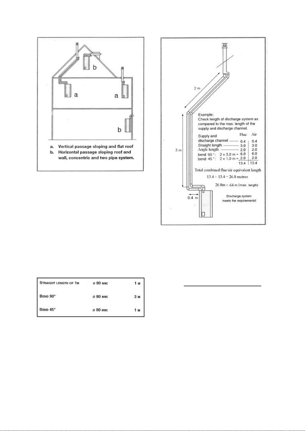
Figure 4: Examples of flueing options.
The equivalent length of the required flue system's
configuration can be calculated from the resistance
factors given for the individual flue components in
table 3. In the worked example (fig 5) the maximum
permitted combined length for a 80mm dia. twin flue
is 64metres at a pressure of 100 Pa. Account has
already been taken of the resistance of the balanced
flue terminal. This can therefore be ignored in the
calculation.
Table 3. Flue resistance factors
Figure 5: Worked flue length example.
6.5 Condensate disposal.
Provisions must be made for the safe disposal of
condensate produced when the Atmos Multi is in
operation. The condensate drainage pipework must
be run in an acid resistant m aterial such as plastic
waste pipe. Copper or steel pipe must not be used.
The pipework must incorporate a minimum 1:20
downward slope towards its point of termination,
which ideally should be an internal soil or waste pipe
to avoid the possible risk of freezing. Alternatively,
where this not possible the condensate may be
discharged into an external gulley or purpose -built
soakaway.
The condensate pipework must be protected against
freezing and any pipework external to the property
must be encased in waterproof insulation and be
restricted to a maximum length of 3m.
ATMOS MULTI version 2002 Page 15
Page 16

6.5 Discharge pipes.
It is a requirement of Building Regulation G3 that any
discharge from an unvented system should be
visible at both the tundish and final point of
discharge. Where this is not possible or practical
however, the discharge must be clearly visible at one
of these locations.
The discharge pipe from the tundish should
terminate in a safe place where there is no risk to
persons in the vicinity of the discharge.
While it is permissible to combine the discharge
pipes from the Atmos Multi temperature & pressure
relief valve and expansion pressure relief valve, the
tundish and Atmos Multi boiler must be located in
the same space. The tundish must also be within
500mm of the combi ned temperature & pressure relief
valve and installed in a vertical position.
While a minimum 300mm of vertical discharge pipe
must exist below the tundish, the discharge pipe
itself should be of metal construction and, unless its
total equivalent length exceeds 9m, be one pipe size
larger than the nominal outlet of the combined
temperature & pressure relief valve.
Where the total equivalent length of the discharge
pipe exceeds 9m the pipe must be increased by one
pipe size for each additional 9m length. For example a
discharge pipe having an equivalent length of
between 9 and 18m must be two pipe sizes larger
than the nominal outlet of the combined temperature
& pressure relief valve, between 18 and 27m three
pipe sizes larger, and so on. Bends must be taken
into account when calculating the flow resistance.
See Figure 6 and Table 4 for a typical discharge
arrangement and worked example.
Note. An alternative approach for sizing discharge
pipes would be to follow BS 8700: 1987 Specification
for design installation, testing and maintenance of
services supplying water for domestic use within
buildings and their curtilages. Appendix E, section
E2 and tables 21.
The discharge pipe must be installed with a
continuous fall towards its point of termination,
which ideally should be below a fixed grating and
above the water seal in a trapped gully. Where this is
not possible or practical then the discharge pipe may
terminate either:
q At low level discharge above external surfaces
such as car parks, hard standings, grassed areas
and so on, providing that termination is a
maximum of 100mm above the surface and a wire
cage or similar guard is fitted to prevent contact
with any discharge, while still maintaining
visibility, or;
q At high level into a metal hopper and m etal
down pipe with the end of the discharge pipe
being clearly visible or alternatively, onto a flat
roof capable of withstanding high temperature
discharges of water. Such termination however,
must not be within 3m of any plastic guttering
and the tundish must be clearly visible in order
to detect any occurrence of discharge.
In cases where a single common discharge pipe
serves a number of units, such as in a block of flats,
the number of units served should be limited to a
maximum of six. The common di scharge pipe should
be at least one pipe size larger than the largest
individual discharge pipe to be connected.
Where the Atmos Multi is installed in a property
where discharge from the unit may not be apparent,
such as in the case of blind, infirm or di sabled
people, then consideration should be given to the
installation of an audible electronically operated
device to warn when discharge takes place.
Combined Safety discharge and condensate pipe
Subject to the approval of the Local Building
Inspector, the Safety discharge pipe and condensate
discharge pipe may be combined into a single
common discharge pipe. A schematic layout for such
an arrangement is given in Appendix 2 of these
instructions.
ATMOS MULTI version 2002 Page 16
Page 17

Worked example:
The example below is for a G ½ temperature relief
valve with a discharge pipe (D2) having 4 No. 22mm
elbows and length of 7m from the
tundish to the point of discharge.
From Table 1
Maximum resistance allowed for a straight length of
22mm copper discharge pipe (D2) from a G ½
temperature relief valve is: 9.0m
Subtract the resistance for 4 No. 22mm elbows at
0.8m each =3.2m
Therefore the maximum permitted length equates
to 5.8m which is less than the actual length of 7m.
Therefore calculate the next largest size (28mm) .
Maximum resistance allowed for a straight length of
28mm-pipe (D2) from a G ½ temperature relief valve
is: 18m
Subtract the resistance for 4 No. 28mm elbows at 1.0
m each = 4m Therefore the maximum permitted
length equates to 14m.As the actual length is 7m a
28mm (D2) copper pipe will be satisfactory.
ATMOS MULTI version 2002 Page 17
Page 18

6.6 Existing systems.
All re-circulatory water systems are subject to
corrosion unless an appropriate water treatment is
applied. To prevent the risk of corrosion sludge
accumulates within an existing system causing
boiler noise and circulation problems along with
possible pump and valve damage, existing heating
systems must be thoroughly flushed to ensure that
all sludge and debris is removed prior to installing
the boiler.
Where a cleaning agent is used for this purpose
only Sentinel X400 is recommended. Atmos Heating
Systems do not recommend the any other cleaning
agent. The use of non-recommended cleaning
agents will invalidate the boiler's guarantee.
Note. When after flushing and cleaning of the
system has taken place there is any possibility of
any debris remaining in the system, it is
recommended that a 'Y' strainer is fitted on the boiler
Return pipe.
7. Boiler Installation.
7.1 Unpacking
Due to the boilers dry weight of 75kg it is
recommend that either a sack barrow or two men are
employed to carry the boiler to its chosen position.
The boiler must be carried and stored horizontally
on the wooden pallet provided. Under no
circumstances must it be stored vertically.
The appliance is protected by a cardboard box and
delivered as standard with:
q Mounting bracket
q Fixing pack consisting of 2 wall plugs, 2 bolts
and 2 washers
q Burner inspection window
q Automatic de-aerator
q Siphon
q Template
q Guarantee registration card, Operating
instructions and Installation instructions
In addition the boiler is supplied with;
q WRAC mains water kit including UV3 cold
water inlet manifold, an 8 litre blue expansion
vessel, safety valve and pipe connections and;
q Robokit sealed system expansion vessel
including wall bracket and safety valve.
Using a knife, cut open the bottom tray of the box
and remove the top box from the bottom tray (fig. 7).
Figure 7: Unpacking boiler
Check the appliance immediately after unpacking.
Any damage must be reported immediately to your
supplier.
The packaging consists of corrugated cardboard,
wood and cellulose oil, and can therefore be
recycled as waste paper. Do not throw away the
packaging, but ask the local refuse collection
service where it can be taken.
Remove the appliance casing to prevent accidental
damaged during installation as follows (fig. 8):
i) Remove the two screws 'a' of the control panel.
ii) Unclick the catches 'b' at the top and bottom of
the appliance and remove case by lifting upwards.
ATMOS MULTI version 2002 Page 18
Page 19

Figure 8: Removing the appliance case.
Figure 10: Dimensions & minimum clearances
7.2. Minimum clearances.
For servicing and maintenance purposes, a minimum
clearance of 600mm to the front, 150mm above,
750mm below and 100mm to either side of the boiler
case is required. (fig. 9 & fig 10)
7.3 Boiler location.
The Atmos Multi is not suitable for external
installations.
While the appliance itself is provided with integral
Figure 9: Dimensions & minimum clearances
frost protection it must however, be installed in a
room that stays free of frost even in extremely cold
conditions. This is to prevent pipes or the safety
valves from freezing. If the selected room does not
ATMOS MULTI version 2002 Page 19
Page 20

meet this requirement, measures must be taken to
protect the safety valves and pipes against freezing.
The appliance must be installed on a flat vertical
wall that is capable of taking the weight of the
boiler. Do not fix directly onto low load bearing or
plasterboard walls.
For low load bearing and plasterboard walls a
special designed mounting frame incorporating
support legs should be employed. Contact Atmos
Heating Systems for this optional item .
On a lightweight block wall, heavy duty Rawplugs
must be used in place of the supplied wall plugs and
bolts.
The boiler may be fitted on or adjacent to a wall
comprising of a combustible material without the
need for a special thermal insulation barrier.
Due to the appliance being self-ventilating, it
remains relatively cool during operation. Generally
there is no requirement to provide purpose made
ventilation to an airing cupboard or compartment in
which the appliance is installed
A cupboard or compartment used to enclose the
appliance must however, be designed and
constructed specifically for the purpose and comply
with Building Regulations. The cupboard or
compartment must also be of sufficient size to
permit access for inspection and servicing or
removal of the boiler.
7.4. Wall mounting the boiler
Taking into account the clearances required for
servicing and maintenance, tape the provided
template onto the chosen wall position, ensuring it
is level and the correct way up.
Mark the position of the fixing holes for the boiler
mounting bracket. Drill the fixing holes using a
16mm drill bit and fit the mounting brack et using the
supplied fixing plugs and bolts.
Fit the appliance onto the mounting bracket as
follows (fig. 11):
a. Place the mounting indication point level with
the top side of the mounting bracket and
position the corners of the back of the casing
level with each end of the mounting bracket.
b. Put the bottom of the boiler against the wall.
c. Carefully lower the appliance onto the wall
bracket.
Note!
A lifting handle with red plastic covers on each
end is provided for lifting the boiler onto the
mounting bracket. Do not lift with other parts of
the boiler, as it may cause damage. To comply with
Health & Safety Regulations, Atmos Heating
Systems recommend that the boiler be lifted into
position by the use of two men.
Figure 11: Mounting the boiler
Warning : The fixings supplied are suitable
only for brick or solid block walls. When full
the Atmos Multi weighs 150kg and must not
be fitted directly onto walls with low load
bearing capacities.
ATMOS MULTI version 2002 Page 20
Page 21

7.5. Connecting the flue system.
Prior to connection of the boiler's flue system please
refer to sections 6.3 & 6.4 of these instructions.
The flue and air duct supplied by Atmos Heating
Systems are an integral part of the boiler and care
must be taken on their installation to ensure that all
joints are airtight and correctly made.
The standard horizontal flue kit supplied with
the boiler consists of a twin pipe terminal plate,
an 850mm length of 80mm diameter aluminium
duct and two 90º bends.
The flue and air ducts may be extended by
means of extensions, (available on request from
Atmos Heating Systems) to a maximum
combined length of 64m. The use of each
additional 90° or 45° bend however, reduces
the maximum permitted flue length by 3m and
1m respectively.
The duct and fittings are push fitted together being
sealed by the fittings integral 'O' ring. (fig 12).
On assembly it must be ensured that aluminium duct
is square and burr free prior to being pushed into
the fitting. Failure to do so may result in damage to
the sealing 'O' ring.
When connecting to the twin pipe terminal plate it is
important to ensure that the plate is fitted the
correct way up and the flue discharge and air inlet
ducts are connected to the correct terminal. (fig 13)
On installing the flue system it is recommended that
a 85mm diameter core drill is used when cutting
through the properties external wall.
For concentric and vertical roof systems refer to
separate installation instructions supplied with the
flue assembl ies.
Figure 12: Twin pipe joint
Figure 13: Twin pipe terminal plate
ATMOS MULTI version 2002 Page 21
Page 22

7.6.Connecting the central heating circuit.
Important Note!
The Atmos Multi is suitable for use on a
sealed heating system only. It must not be
connected to an open vented heating
system.
22mm diameter connections for the central heating
circuit flow and return pipes are located on the
underside of the appliance. (fig 14) The flow pipe
being colour coded red, the return pipe colour coded
blue.
Figure 14: Boiler flow & return connections .
Locate and fit the separately supplied automatic air
vent to the boiler's top right corner (fig 15). Once
fitted loosen the automatic air vent's cover cap.
Figure 15: Automatic air vent
The system must comply with the requirements of
BS5449 and to avoid corrosion and leaks, be
airtight, closed and connected in accordance with
Benchmark procedure.
When connecting the boiler to a heating system
containing plastic pipew ork the following must be
noted:
q In a floor heating system, the plastic
hoses/pipes used must either meet BS7291 having a
class 'S' rating or DIN 4726/4729 having an air
permeability less than 0·1 g/m³ at 40ºC.
q In a radiator system, the plastic hoses/pi pes
used must either meet BS7291 having a class 'S'
rating or DIN 4726/4729 having an air permeability
less than 0·1 g/m³ at 85ºC in a twenty four hour
period.
Connection of the Atmos Multi to a heating system
containing non-diffusion barrier oxygen permeable
plastic pipe or class 'H' plastic pipe will invalidate
the boilers guarantee.
It is important that there is a by-pass on the central
heating circuit to ensure that the system water is
able to flow through the boiler's heat exchanger at
all times. Thi s may be achieved by leaving at least
one radiator permanently open. Alternatively, a
pressure differential regulator valve (fig16) that
provides an automatic system by pass is available
on request from Atmos Heating Systems.
Figure 16: Pressure differential regulator valve
Before connection to the central heating system the
system must be must be thoroughly flushed in
accordance with the guidance given in BS7593.
ATMOS MULTI version 2002 Page 22
Page 23

A sealed system 'Robokit' is supplied with each
Atmos Multi boiler. Expansion vessels are available
in 8,12 or 18 litre sizes with the Robokit,
and are coloured RED. Table 5 provides guidance
to the size of expansion vessel required for systems
fitted with steel panel radiators in a two-storey
house. Consult Atmos Heating Systems for further
information and advice for non-standard systems.
Note. The red primary expansion vessel must not be
confused with the blue secondary expansion vessel
intended for use on the domestic hot water circuit.
Table 5: Required expansion vessel
Where required, the boiler offers the facility for an
independent towel rail circuit to be installed via the
purpose supplied towel rail connection (fig 16a)
This allows for the separate heating of a radiator
when the boiler is operating in either central heating
or hot water mode. To prevent hot water circulation
within the central heating system when the boiler is
operating in domestic hot water only mode, the
towel rail circuit return must be the last connection
on the return pi pe to the boiler.
Note. When utilised, the towel rail circuit must be
carefully balanced to avoid short-circuiting of the
main central heating system.
Figure 16a Towel rail connection
Figure 17: Pre-assembly kit
From the pre-assembly kit (fig 17) select the
Assembly 1 and fit to the 22mm central heating
return on the boiler, utilising the 22mm compression
straight connector supplied.
Using the wall bracket supplied, fit the Red
expansion vessel to the wall in close proximity to
the boiler. Connect the expansion vessel to the
15mm pipe connection g. This can be with either
15mm copper tube or alternatively, using optional
ATMOS MULTI version 2002 Page 23
Page 24

flexible hose connections available as an optional
extra from Atmos Heating Systems. The connection
to the expansion vessel utilises a ¾ female x ½ male
threaded adaptor and the washer provided must be
fitted internally. The other end has a 15mm
compression fitting.
Fit the filler loop from the cold water main to the
second 15mm pipe connection d, ensuring that the
loop is fitted in the right direction as indicated on
the arrow stamped on the non-return valve.
Fit the heating system safety valve into the ½"
BSPF connection, pointing in the direction shown
ready for connection into the discharge pipe. (fig
18)
7.7.Connecting the mains cold water.
Each Atmos Multi boiler is supplied with a mains
pressure kit comprising the following components:
q UV3 manifold including pressure reducing valve
pre-set at 3.5 bar. (Altecnic)
q ½" Caleffi safety relief valve set at 6bar.
q 8 litre blue potable expansion vessel (Altecnic)
q Expansion vessel mounting bracket.
q 22mm x 15mm compression reducing set.
q Black plastic tundish. (Altecnic), and;
q ¼" BSPM drain cock.
The mains pressure kit must be assembled as shown
in fig 18 in the following manner:
Figure 18: Mains pressure kit assembly
q Connect the UV3 manifold to the boilers15mm
cold water inlet supply pipe (colour coded blue),
using the 22mm x 15mm compression reducing set
supplied.
q Connect the 22mm incoming cold water main
supply to the inlet of the UV3 combined 22mm stop
tap and pressure reducing valve.
q Locate and fit the 6bar safety relief valve, by
push fitting into its fixing socket on the UV3
manifold. A small grub screw located in the side of
the manifold is provided to lock the valve in
position, by means of the Allen key provided.
q The 22mm branch 'E' is provided for the cold
water system of the house, where equal hot and
cold water pressures are required. If this facility is
not required, the branch may be blanked off using
the blanking plug provided.
q Locate and fit the supplied ¼" BSPM drain-off
cock to the manifold's socket 'G'. The fitting of this
drain off cock enables 90% of the water content of
the hot water tank to be drained.
q Fix the Blue 8 litre potable expansion vessel
adjacent to the 'primary' heating expansion vessel
using the wall brackets provided.
q Connect the potable expansion vessel's ¾" boss
to connection 'H' on the UV3 manifold using 15mm
ATMOS MULTI version 2002 Page 24
Page 25

copper pipe.
r no circumstances must any valve be
installed between the expansion vessel and
Important Note!
Unde
connection 'H' on the UV3 manifold.
q Connect the 6 bar safety valve discharge pipe as
described in Section 7.6 of these instructions.
Warning!. Failure to install the above components
correctly is dangerous, and renders the system
unsafe. Furthermore the copper tank guarantee is
invalidated.
7.8.Connecting the safety discharge pipes.
The safety discharge pipes must be assembled as
shown in fig 19 in the following manner:
Figure 19: Safety discharge pipes
Test Hole
copper tee and pipe.
q Connect the black tundish as illustrated. The
tundish must be located in a position where it is
clearly visible to the householder and away from
any electrical devices or wires.
q Connect the 'primary' heating expansion vessel's
pressure relief valve discharge outlet to the under
side of the tundish using a 22mm x15mmx 22mm
copper tee
q A straight vertical pipe with a minimum length of
300mm must be provided below the tundish before
the fitting of any bends.
q The discharge pipe must be ran to an external
drain, terminating in a safe place where there is no
risk to persons in the vicinity of the discharge. The
discharge pipe must consist of metal, preferably
copper.
q If the length of discharge is more than 9m
equivalent length (a bend has an equi valent length
of 0·8m) a larger pipe must be fitted. (see Section 6.5
of these instructions).
q The discharge pipe must have a continuous fall
towards its point of termination, in order to drain
effectively.
q The discharge pipe point of termination should
ideally be below a fixed grating and above the water
seal in a trapped gully. If this is not possible then
refer to Section 6.5 of these instructions for
acceptable alternative discharge terminations.
q The discharge pipe must not be used for any
other pur pose.
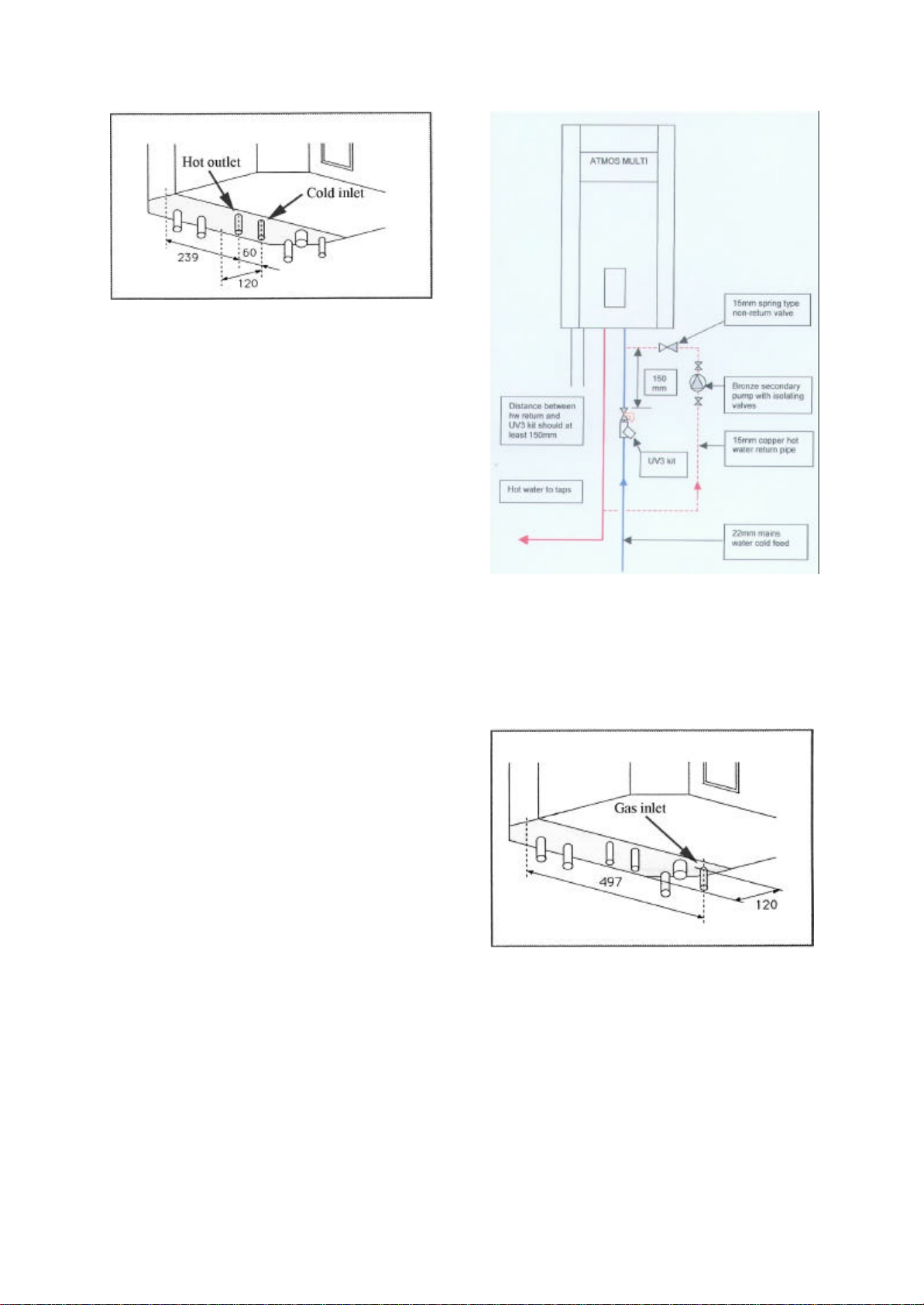
7.9.Connecting the domestic hot water supply.
The cold water inlet and hot water outlet connection
points for supplying domestic hot water are located
on the underside of the appliance (fig 20). The cold
water inlet being colour coded blue, the water outlet
colour coded red.
Figure 20: Hot water connections.
q Connect the boiler's integral temperature &
pressure relief valve discharge outlet and the
discharge outlet of the 6 bar pressure relief valve
fitted to the UV3 manifold, by means of a 15mm
ATMOS MULTI version 2002 Page 25
Page 26
The cold water inlet to the boiler must be made via
the UV3 manifold. The properties hot water supplies
are connected to the boiler via the 15mm diameter
hot water outlet connection.
The boiler's minimum domestic hot water
temperature setting is 60°C., the installation of a
thermostatic mixing valve is recommended to reduce
the hot water temperature at the tap.
7.9 Hot water secondary circulation.
While there is no separate secondary return
connection on the boiler, a secondary re-circulation
loop may be installed. Where required, the
secondary return should be taken to the cold water
feed of the storage tank, immediately after the UV3
manifold. The return must not pass through the UV3
manifold. If the secondary return loop has a volume
in excess of 1 litre, a larger potable expansion vessel
should be used. Contact Atmos Heating Systems
for further advice.
A non-return valve must be fitted to the return loop
to prevent the back flow of cold water to the hot
water taps. (Fig 20a)
7.10.Connecting the gas supply.
The gas pipe inlet connection is located on the
underside of the appliance being colour coded in
yellow. (Fig 21)
Figure 21: Gas inlet connection
Figure 20a Hot water secondary circulation
Check the boiler's data plate to ensure that the
appliance has been set for the correct gas supply.
The boiler is available for either Natural Gas (G20) or
propane (G31).
For Natural gas the supply pipe must have a
minimum diameter of 22mm. The meter governor
should deliver a dynamic pressure of 20mbar for
natural gas or 37mbar for propane.
ATMOS MULTI version 2002 Page 26
Page 27

The ¼ turn gas tap provided must be fitted
immediately to the boiler to enable complete gas
isolation to the boiler during maintenance and
servicing work.
To prevent the ingress of foreign matter and
possible damage to the gas-regulating block, the
gas supply pipe must be checked for contaminants
prior to connection to the boiler.
On final connection of the gas supply to the boiler,
the complete gas installation, including the meter,
must be tested for gas soundness and purged as
described in BS6891.
7.11. Connecting the condensate siphon
The connector for the condensate water discharge
is located on the underside of the appliance (fig. 22).
Figure 22: Condensate connection.
Locate and connect the supplied siphon to the
boilers condensate drain connection via 32mm dia
plastic pipe. The siphon should be fitted so its
outlet is angled towards the rear wall and left with
an open connection to the purposely installed 32mm
dia condensate drainage pipe work. (fig 23)
For condensate drainage pipework refer to Section
6.5 of these instructions.
Figure 23: Condensate discharge arrangement.
7.12. Connecting the mains electricity.
Warning! The electrical wiring of the
Atmos Multi is complete and must
not be changed or adapted in any
All electrical connections to the mains supply must
be made in full accordance with the current I.E.E.
regulations.
The boiler must be earthed and connected via a
double pole isolating switch fused to 3 amp or
alternatively, by the use of a 3 amp fused three pin
plug and unswitched shuttered socket outlet
Where possible, it is recommended that the
appliance is protected against electrical surges by
the fitting of an anti -surge device.
On connection it is essential that correct polarity be
observed. If polarity is reversed, the control unit will
lock and a malfunction alert ‘L’ will be displayed on
the control panel. Should this occur, the wiring must
be reversed to its correct polarity and the boiler restarted
A facility for the connection for a 24V AC room is
ATMOS MULTI version 2002 Page 27
Page 28

located behind the control unit front fascia.
Important Note!
Under no circumstances must any electrical
power be input to the room thermostat terminals.
Care must also be taken to avoid induced
voltages caused by the running of the
thermostat cables along side other main voltage
cables.
On connection the room thermostat's heat
accelerator must be set at 0·12A. The maximum
permissible resistance of the room thermostat circuit
is 22 Ohms. Where a clock thermostat is employed,
the closed-circuit current must not exceed 20mA
when there is no demand for heat.
It is recommended that the room thermostat is not
set lower than 15ºC during the winter months.
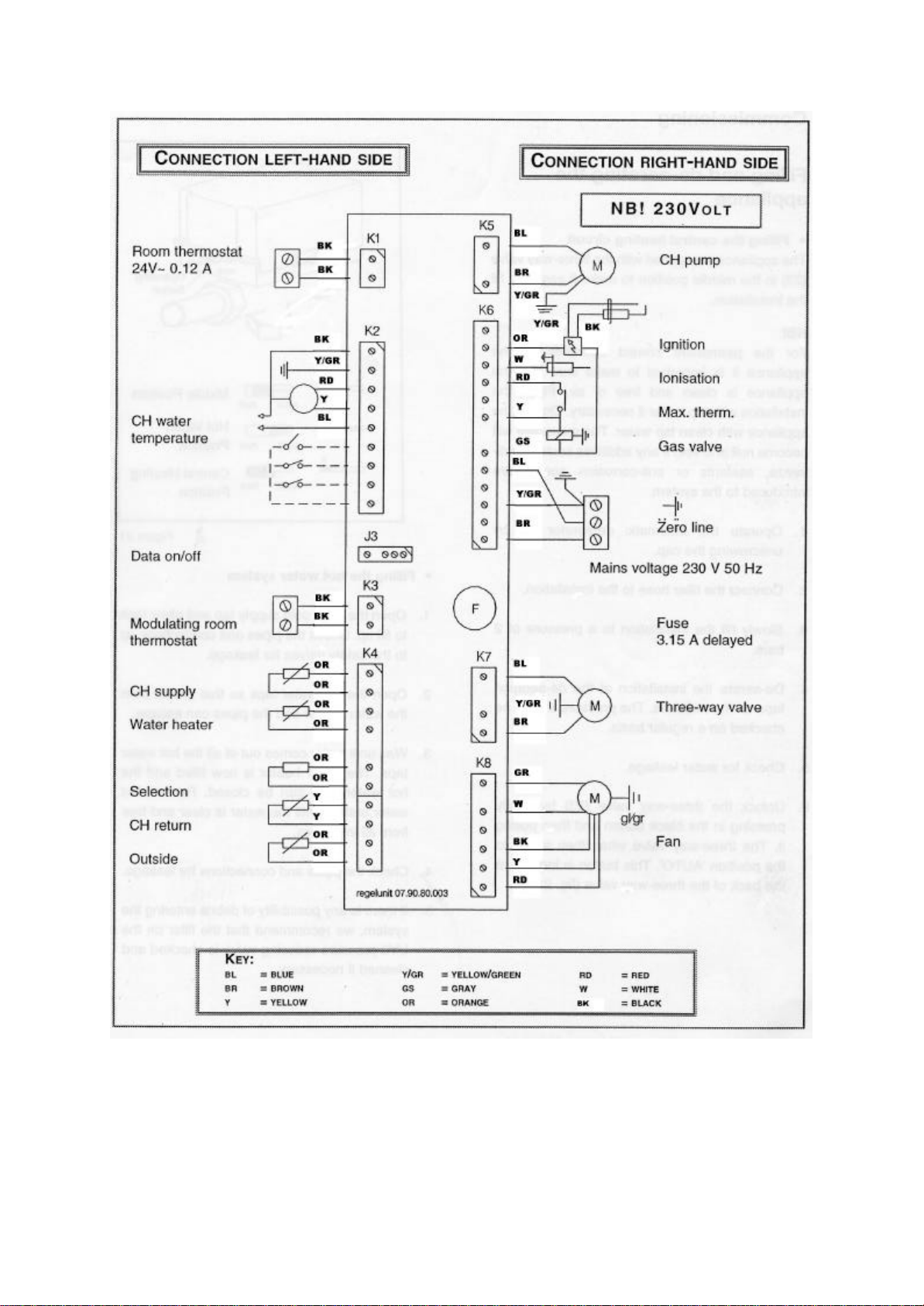
Figure 24: Atmos Multi wiring diagram .
Where a 'wireless' room thermostat is employed
consult the thermostat's manufacturer instructions
for installation.
A wiring diagram of the Atmos Multi is given as
figure 24.
ATMOS MULTI version 2002 Page 28
Page 29
8. Commissioning.
Note: We include Benchmark Logbooks with
every boiler and advise that they are filled in during
the commissioning procedure.
ATMOS MULTI version 2002 Page 29
Page 30

8.1 Filling the heating system.
Warning! The Atmos Multi must not be operated
in a waterless condition.
On completion of the boiler installation and
ensuring that all water connections are correctly
made and tight, the boiler may be filled with clean
water by fitting the supplied filling hose and
opening the two Robokit manual filling valves. (fig
25)
Figure 25: Filling hose connection.
q Test the operation of the system’s outlet safety
valve by turning the valve knob anti -clockwise until
water is released, at which point the valve must be
closed and re-set.
q Continue to fill the system until all air has been
expelled, leaving the system pressure at a nominal
2bar.
q Check the system for water soundness,
rectifying where necessary and remove the system
filling hose.
Figure 27: Three-way valve
On filling:
q Ensure that the boiler's automatic air vent
sealing cap is loose.
q Slowly fill the installation until a system
pressure of 2bar is obtained.
q Vent each system radiator and purpose fitted air
vent in turn starting with the lowest in the system.
The system pressure should be regularly monitored
during this process and topped up when required.
q Air must be vented from the boiler pump by
unscrewing the pump’s integral vent plug (fig 26)
and allowing water to bleed for a few seconds,
taking care not to allow water to splash onto the
boiler's electric parts. This process may have to be
repeated two or three times during the filling
process.
Figure26: Venting the pump
To aid filling the boiler is supplied with its integral
three way valve locked in the middle position. On
completion the valve must be unlocked by lightly
ATMOS MULTI version 2002 Page 30
Page 31

pressing and then pulling the black button located
on the rear of the valve. (fig. 27).The three way
valve will then return to the 'Auto' position.
Where required Sentinal X100 may be added to the
system water in accordance to its manufacturer
instructions. Atmos Heating Systems do not
recommend the use of any other inhibitor or
additive. The use of a non-recommended inhibitor
or additive will invalidate the boiler's guarantee.
Note! For existing central heating systems the final
system water must have a pH value of between 6.5
and 8.
8.2 Filling the domestic hot water system.
q Open the UV3 combined stop tap and pressure
reducing valve and allow the storage tank to fill with
water. Check the pipework and connections up to
the safety valves for leaks.
q Vent the domestic hot water system by opening
all hot water outlets until water is discharged.
q Turn off the hot water outlets once the
discharge water is clear and free from impurities.
q Check the system for water soundness,
rectifying where necessary.
Note! If there was any possibility of debris entering
the domestic hot water circuit during filling, the filter
on the UV3 pressure-reducing valve must be
removed and cleaned as necessary. (fig 28)
8.3 Appliance operation.
The appliance may be put into operation by the
follow procedure:
q With the appliance manual gas tap in the 'off'
position, switch on the electrical supply to the
boiler. If a letter 'L' appears on the diagnostic
display the boiler has been wired with reversed
polarity.
q Check that the water pressure in the central
heating circuit is approximately 2 bar at the
appliance. If the central heating water pressure is
below 0·5 bar or higher than 3 bar a letter 'C'
Figure 28: UV3 cold water filter
alternating with the work status of the appliance will
be shown by a warning report on the diagnostic
display. (see Section 12.). If this report is shown the
appliance will only run at its minimum capacity.
q Switch off the domestic hot water heating by
pressing the 'Hot water' button on the operating
panel. The 'on' indication light will go out.
q Open the appliance gas tap and purge the gas
supply if necessary via the measurement nipple
provided for measuring the pre-pressure (fig. 29).
Figure 29:
q Set the room thermostat at its highest position.
The appliance will now start (status report Code 2º).
If the hot water temperature is under 8ºC, the frost
protection will cut in and the boiler will automatically
ATMOS MULTI version 2002 Page 31
Page 32

revert to raising the hot water temperature above
water the room thermostat also makes a
15ºC (status report Code 3•).
Note! If air is still present in the gas supply, the
boiler's burner may attempt to ignite once or several
times. After four start attempts a flame malfunction
will be indicated (flashing 3•). If this occurs, unlock
the control unit by pressing the reset button. The
appliance will now run for the first 3 minutes at the
lowest capacity and will switch to its maximum
capacity until the central heating water temperature
has fallen below 80ºC. The appliance modulates
between 80ºC and 90ºC.
q If the boiler's burner fails to ignite after 3 reset
attempts, re-purge the gas supply, using the prepressure measurement nipple. Otherwise consult the
Atmos Multi Service Manual.
q Ensure that the appliance is functioning
correctly by undertaking the following inspections
and noting the results and work carried out on the
Service Card located on the front of the boilers
storage tank insulation shells:
1. Visual inspection of the combusti on flame
2. Measurement of the gas flow rate by watch &
meter.
3.Measurement of either the O2 or CO2 percentage
concentration within the flue gases by flue gas
analysis.
4.Measurement of gas pre-pressure
q The procedure required to undertake
inspections 1, 2 & 3 are detailed in Section 10 of
these instructions. The procedure for inspection 4
is as follows:
v The measurement of gas pre-pressure must be
taken during burner operation at maximum heat
input via the measurement nipple provided on the
gas valve. (fig 22). The gas pre pressure reading
must be at least 20mbar.
q Check the burner's gas rate by stopwatch and
meter. On the maximum input of 24kW or 32kW
(depending on boiler model) the time taken to use 24
litres or 32 litres of gas respectively should be 33
seconds (± 2seconds.)
Note! The appliance burner pressure is factory set
and sealed. The burner pressure can only be
measured using precisely calibrated CO2 or O2
measuring instruments. If an inaccuracy is found
when checking the appliance gas rate then consult
the separately available Atmos Multi Service
Manual or contact Atmos Heating Systems.
q Set the room thermostat to its minimum setting.
q Switch on the hot water heating by pressing the
hot water button. The 'on' indication light will
illuminate. The thr ee-way valve will switch over to
the water heater position and the burner will ignite
to the stored domestic hot water. (status report
Code 1•).
q While the stored domestic water is heating,
check that expansion water is entering the tundish
of the discharge system.
q Reset the room thermostat back to the desired
position.
Note!
If during the heating of the stored domestic
demand for heating, the hot water and central
heating demand will be met simultaneously
(status report Code 4•).
The following codes may also appear on the
diagnostic display during the commissioning
process:
§ (1•) Heat demand water heater
§ (2•) Heat demand central heating
§ (3•) Heat demand water heater and
§ (4•) Heat demand water heater and
8.4 System balancing.
For efficient boiler operation the heating system
must be correctly balanced to ensure that all
C/heating, priority water heater
heating
C/heating, supply to both.
ATMOS MULTI version 2002 Page 32
Page 33

radiators are heating up evenly and a required
temperature differential of 20ºC is present between
the boiler's heating flow and return connections.
The required water flow rate through the appliance
is 0·8 m³/h and 1·2 m³/h for the Atmos Multi 24 and
32 models respectively. The maximum permissible
system resistance to enable the boiler pump to
achieve these flow rates is 3·1m and 2·1m
respectively. (fig 30)
Figure 30: Available pump outputs
9. System shutdown.
9.1 Central heating circuit.
q Leave the appliance connected to the main
electrical supply.
q Turn the room thermostat to its minimum
setting. The domestic water heater will remain
at its set temperature setting.
Note! On shutting down the central heating system
it is recommended not to set the room thermostat
lower than 15ºC during the winter months. To
prevent the installation from freezing it is
recommended leave all radiator valves fully or
partially open.
9.2 Domestic hot water.
q Leave the appliance connected to the main
electrical supply.
q Switch off the domestic hot water by pressing
the 'Hot water' button. The ‘on’ indication light
will go out. (The stored water is protected
against freezing in winter months by an
automatic frost protection that activates on a
water temperature of 15ºC).
Note! The heating and domestic hot water
installation must be independently protected from
frost. The boiler's built-in frost protection facility
will only safeguard the appliance itself.
9.3 Draining the boiler
Hot water tank
q Turn off the cold water mains stop tap and
open the domestic hot taps.
q Connect a flexible hose from the black drain tap
on the UV3 manifold, into the tundish. The
water from the hot water tank will now flow into
the waste pipe via the funnel of the Safety
Valve group.
Alternatively, the tank may be drained via the safety
valve on the UV3 manifold. The valve head should
be rotated through 90º and held open until water
stops flowing.
Central heating circuit.
q Switch off the boiler electrical supply.
q Set the three-way valve (fig 27) at the middle
position by pressing in the black button until it
locks
q Allow the installation to drain using the
purpose fitted drain cocks.
9.5 Disposal of the appliance
The Atmos Multi is made of a number of primary
materials, especially copper, aluminium and steel.
These materials can easily be separated and
recycled at the end of the life span of the appliance.
Therefore do not throw away the appliance, but
make enquiries at your local council or a scrap
dealer.
10. Routine Inspection and Servicing.
To ensure continued efficient operation of the
Atmos Multi it must be checked and serviced as
necessary at regular intervals. The frequency of
servicing depends upon the individual installation
conditions and usage, but must be a minimum of
once per year.
The extent of the servicing required is determined
by the operating condition of the appliance when
ATMOS MULTI version 2002 Page 33
Page 34
tested by a fully qualified engineer.
Only competent engineers such as a Corgi
registered installer must carry out any service work.
10.1 Boiler pre-service inspection.
Warning!
Turn off the boiler electrical supply before
removing the appliance casing. The fan, gas
valve, three-way valve and central heating
pump are mains fed with 22OV
The annual inspection of the boiler comprises of the
following:
1. Visual inspection of the flame
2. The measurement of the O2 or CO2
concentration in the flue gas
3. Measuring the gas rate.
4. Inspecting the ionisation flow.
5. Inspecting the ai r inlet filter.
6. Inspecting the siphon.
Note! The inspection results and any
servicing work undertaken must be noted on
the service card located on the front of the
hot water storage tank insulation shells.
1. Visual inspection of the flame
The flame must be assessed after one minute of
combustion at the low position or high position.
q Low position
Viewed from top to bottom on the combustion seat
the burner flame picture must have the presence of a
light blue flame.
A completely red flame indicates that the supplied
air/gas mixture is gas rich, an entirely dark blue
flame indicates an air rich mixture.
If the flame picture is correct there is no need to
measure the O2 or CO2 concentration of the flue gas
and point 2 of the inspection can be left aside. If the
flame picture is not correct, the O2 or CO2
percentage of the flue gas must be measured.
q High position
Viewed from top to bottom on the combustion seat
the burner the burner flame picture must have the
presence of an entirely blue flame. The air/gas
mixture setting of the high position are determined
by the setting of the low position.
If the flame picture is not correct, the O2 or CO2
percentage of the flue gas must be measured.
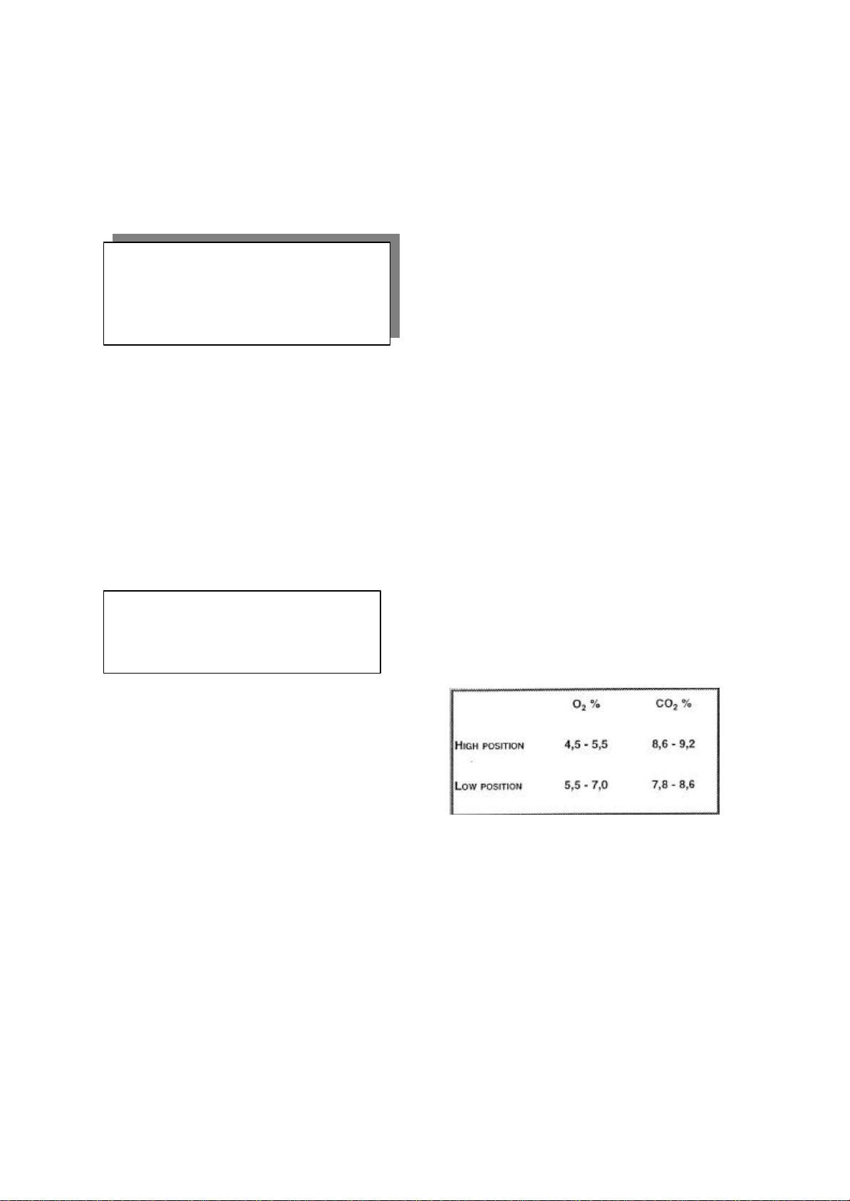
2. Measuring the O2 or CO2 concentration of the
flue gas.
The O2 or CO2 measurement of the flue gas must be
undertaken using an analyser calibrated to a
precision of < 0,2%.
Measurements of the flue gas O2 or CO2
concentration must be taken at both the burner's
low and high input capacity settings. The low input
setting must be the first measurement.
On initial start up the burner fires on high input
capacity prior to reverting to low input capacity for
3 minutes. After which per iod the burner again
reverts back to high input capacity.
The measured O2 or CO2 must fall within the limits
given in table 6.
Table 6. O2 and CO2 limits
Note the measured values on the service card
situated in the inside of the appliance. Compare the
new values with those measured when the
appliance was put into operation and/or during the
previous inspections. If the differences between the
two values are considerable, consult the Atmos
Multi Service Manual or contact Atmos Heating
Systems.
3. Mea suring the gas rate.
ATMOS MULTI version 2002 Page 34
Page 35

Check the burner's gas rate by stopwatch and meter.
On the boilers maximum burner input of 24kW or
32kW (depending on boiler model) the time taken to
use 24 litres or 32litres of gas respectively should be
33 seconds (± 2seconds.)
Note! If the flue's 80mm-diameter gas discharge duct
is longer than 10 metres at the gas rate will be
adversely affected and the measured time will in this
case increase by 2%.
Note the measured value on the appliance service
card. Compare the measured time with the value(s)
recorded last time the appliance was put into
operation and/or the previous annual inspection.
If the measured time falls outside of the tolerances,
inspect the air supply and flue gas discharge
system and the heat exchanger of the appliance for
soiling, and clean where necessary (see Section
10.3).
5. Measuring CO2 percentage of the flue gases.
Use a Flue gas analyser with a precision of <0.2% to
check the CO2 percentage of the Flue gases.
Flue gas samples can be taken from the test hole at
the left-hand side of the outlet casing. (See fig. 19)
6. Inspecting the lonization flow.
The ionisation flow of the burner can be read off via
the Service Programme of the control unit. Consult
the Atmos Multi Service Manual for the access
procedure for the Service Programme. The
ionisation flow should be greater than 30 for both
the low and high positions. If there are differences
the ionisation probe must be examined and replaced
as necessary (see Section 11.4).
7. Inspecting the air inlet filter.
The air inlet filter situated on the appliance's
combustion air inlet must be inspected for damage
and cleaned or replaced where necessary.
8. Inspecting the siphon.
Remove the siphon cap at the bottom of the
appliance and check the cap for the presence of
aluminium oxide.. If a quantity of aluminium oxide is
present, the heat exchanger will require cleaning
(see Section 5.2). The siphon cap must be firmly
replaced following inspection.
10.2 Auxiliary equipment inspection.
The annual inspection of the boiler's auxiliary
equipment comprises of checking the following:
1. Operation of safety relief valves
2. Operation of pressure reducing valve
3. Expansion vessels pre-charge
1. Safety relief valves.
Three safety relief valves are fitted to the system,
two are external to the boiler and one internal. The
valves operation may be checked by rotating the
cap of the valve through 90º, which will result in a
discharge of water from the valve. If there is no
discharge, check that the system is correctly
pressurised, if so replace the defective valve.
Check that there is no discharge leak when the
valves are returned to their closed position.
2. Pressure reducing valve
Turn off the cold water supply and remove the
pressure reducing valve's head from the UV3
manifold. Check the gauze filter and clean or replace
as necessary.
Check the water pressure at the valve outlet is no
higher than 3·5bar. If the pressure is higher than
3·5bar then recalibrate or replace the valve as
necessary.
3. Expansion vessels
q Domestic hot water vessel. (Blue)
Turn off the mains cold water supply stop tap and
depressurise the hot water system. Apply a suitable
air pressure gauge to the vessels air valve. The
pressure should be 3·5bar. If below 3·5bar the vessel
must be re-pressurised or replaced.
ATMOS MULTI version 2002 Page 35
Page 36

Before servicing the boiler, isolate the
q Heating system vessel (Red)
Isolate the boiler and depressurise the heating
system. Follow the procedure for the domestic hot
water vessel ensuring the pre charge pressure is as
stated on the expansion vessel label. (Normally 1·5
bar)
10.3 .Servicing the boiler.
Warning!
electrical supply and close the boiler's gas
service control tap. Allow the boiler to cool
before commencing work.
Gas soundness checks must always be carried out
following servicing of any gas-carrying component.
Following servicing work, electrical system safety
checks must always be undertaken using a suitable
instrument prior to reinstating the electrical supply
to the appliance.
Correct boiler servicing comprises of the following:
1. Cleaning the appliance outlet casting.
2. Inspecting the burner unit.
3. Cleaning the heat exchanger.
4. Inspect air supply/flue gas discharge system.
5. Unvented hot water tank inspection.
1. Cleaning the outlet casting
Using a 8mm socket, release the 3 fixing nuts
securing the outlet casting to the base of the heat
exchanger and remove the casting by gently
separating it from the push fit connection with the
condensate tr ap. (fig 31)
Remove the flue baffle by turning its base locking
'T' bar through 90º.
Inspect the outlet casting and baffle, cleaning where
necessary.
Figure 31: Outlet casting
Figure 32: Flue baffle
2. Inspecting the burner unit
Disconnect the gas supply from the gas valve via
the connecting joint union and release the 3 fixing
nuts securing the burner to the inlet casting, using
an 8mm socket. (fig 33)
Disconnect the push on electrical connections to
the fan, high temperature thermostat, ignition
electrode and ionisation electrode.
Figure 33: Removing burner assembly.
ATMOS MULTI version 2002 Page 36
Page 37

The heat exchanger must be cleaned on at least
Do not use a brush with metallic bristles, as this
will
Lift and remove the burner assembly from the
appliance.
Inspect the ignition electrode and check the
electrode's distances between the burner and earth
pin are 5mm and 3·5mm respectively. (fig 34).
Replace or adjust the electrode as necessary
Inspect the ionisation electrode and check the
distance between the electrode and the burner is
10mm. Replace or adjust the electrode as necessary
Figure 34: Ignition electrode.
Inspect the fan and the inner grating of the burner
and clean where necessary using a soft brush or
compressed air.
Inspect the inlet casting sealing gasket and replace
if necessary. (fig 35)
Figure 35: Inlet casting seal
3. Cleaning the heat exchanger.
Inspect the heat exchanger from the topside of the
appliance and remove any deposits from the heat
exchanger and fins using a soft brush.
Important!
every third service inspection.
damage the heat exchanger.
A purpose made heat exchanger cleaning brush
(article number 93.98.12.410) is available on
request from Atmos Heating Systems.
Re-assemble the boiler, fitting the burner assembly,
flue baffle and outlet casting in reverse order to
dismantling. Ensure all components are correctly
sealed and located.
4. Inspection of air/flue gas discharge system.
Inspect the air supply /flue discharge system
throughout its entirety ensuring that it is in sound
condition with no damage to the pipework or joints.
Inspect the terminals and their position ensuring
they are clear and unobstructed, taking remedial
action where necessary.
5. Unvented hot water tank inspection.
Remove the hot water tank's insulation shell
ensuring it is intact and free from damage replace if
necessary.
Visually examine the domestic hot water tank for
ATMOS MULTI version 2002 Page 37
Page 38

signs of damage or water leaks, taking remedial
action where necessary.
10.4. Completion of inspection and servicing.
On completi on of the annual inspection and service
the boiler must be checked for correct operation and
all controls returned to their original settings, as
found.
Where applicable check the Sentinal X100 inhibitor
concentration level within the system water,
toppin g up when necessary.
11. Component Replacement.
Warning! When replacing components,
isolate the electrical supply and close the
boiler's gas service control tap. Allow the
boiler to cool before commencing work.
The replacement of the following components does
not require draining of the boiler.
11.1 Gas Valve.
Disconnect the gas supply from the gas valve to the
burner assembly via the connecting joint union and
remove the valves 'Push' on electrical connections.
(fig 36)
Unscrew and remove the gas injector nozzle from
the gas valve assembly. (fig 37)
Release the valves four fixing bracket retaining bolts
using an 8mm spanner and remove gas valve. (fig
38) Fit replacement gas valve in reverse order.
Figure 36
Figure 38
Reinstate boiler operation and check gas valve
settings (Refer to section 10.1)
11.2 Fan
Disconnect the gas supply from the gas valve to the
fan via the connecting joint union. (fig 36) and
remove gas supply tube from the fan inlet
connection.
Release the four nuts securing the fan to the burner
manifold using a 7mm socket. (fig 39)
Fit replacement fan in reverse order.
Figure 39.
Figure 37
ATMOS MULTI version 2002 Page 38
Page 39

11.3 Ignition transformer.
Disconnect the 'push' on electrical connections and
release the transformers two cross-headed fixing
screws. (fig 40)
Fit new transformer in reverse order ensuring
correct connection of the power supply to terminals
1 & 2 and ignition out from terminals 3 & 4.
Warning! Incorrect connection to the
transformer terminals will result in blowing the
boiler control unit.
Figure 40
distances between the burner and earth pin are 5mm
and 3·5mm respectively.
q Ionisation electrode. Detach the ionisation
electrode from burner manifold by releasing the two
cross-headed fixing screws. (fig 41) Fit new
electrode in reverse order checking that a 10mm gap
exists between the electrode and burner.
q Sight glass. Detach the sight glass from burner
manifold by releasing the two cross-headed fixing
screws. (fig 41) Fit new sight glass in reverse order
replacing the sealing gasket.
Figure 41
11.5 High limit thermostat.
Disconnect the thermostat's 'push' on electrical
connections and unscrew the thermostat from its
fitting using a 17mm socket (fig 42).
Fit replacement thermostat in reverse order.
Figure 42.
11.4 Burner, Ignition electrode, Ionisation
electrode and Sight glass.
Disconnect and remove the boiler burner assembly
(Refer to section 10.3)
q Burner. Detach the burner from the manifold by
releasing the three fixing nuts using an 8mm socket.
(fig 41). Fit the new burner in reverse order replacing
the burner manifold gasket.
q Ignition electrode. Detach the ignition electrode
from burner manifold by releasing the two crossheaded fixing screws. (fig 41) Fit the new electr ode
in reverse order checking that the electrode's
ATMOS MULTI version 2002 Page 39
Page 40

Figure 44
11.6 Pressure sensor.
Disconnect the pressure sensor 'push' on electrical
connections and gently unscrew from its fitting by
hand. (fig 43).
Fit replacement pressure sensor in reverse order.
Figure 43
11.7 Hot water temperature sensor.
Disconnect the sensor's electrical connections and
unscrew the hot water temperature sensor from its
fitting using an 8mm spanner .(fig 44).
Fit the replacement sensor in reverse order.
11.8 Control Unit.
Disconnect the electrical supply cable to the boiler
from the mains isolation switch.
Remove the boiler components 'plug' in electrical
connections from the control unit (fig 46) and
remove control panel by gently pulling it forwards.
Fit replacement control panel in rever se order
checking that correct polarity is maintained on
connection to the mains isolation switch.
Note! The replacement of the following
components requires the boiler to be drained.
For draining the boiler refer to section 9.3 and
section 8.1 for re-filling the boiler.
11.9 Pump head.
Disconnect the electrical connections from the
pump terminal block. (fig 45).
Release the two bolts securing the pump head using
a 5mm-hexagon key. and remove the pump head
from the pump body.
Fit replacement pump head in reverse order. The
pump must be vented via its vent plug on refilling of
the boiler.
Figure 45
ATMOS MULTI version 2002 Page 40
Page 41

11.11 Heating water temperature sensor.
Disconnect the heating hot water temperature
sensor electrical connections and unscrew the
sensor from its fitting using a 15mm spanner (fig 48).
Fit the replacement sensor in reverse order.
Figure 48
11.10. Three way valve.
Unplug the three-way valve's electrical connections
from the boiler control unit (fig 46)
Disconnect the three compression pipe connections
To the valve and remove valve. (fig 47)
Fit replacement three way valve in reverse order.
Figure 46
Figure 47
11.12 Temperature & pressure relief valve.
Drain the domestic hot water system (refer to
section 9.3)
Release the valve's outlet 22mm compression fitting
to the discharge pipe. (fig 49)
Unscrew the temperature & pressure relief valve
and remove.
Fit replacement valve in reverse order using a
sealant suitable for potable water.
Figure 49
11.13. Hot water tank.
Disconnect and remove the following boiler
components:
q Gas valve
q Fan/burner assembly
q High limit thermostat
ATMOS MULTI version 2002 Page 41
Page 42
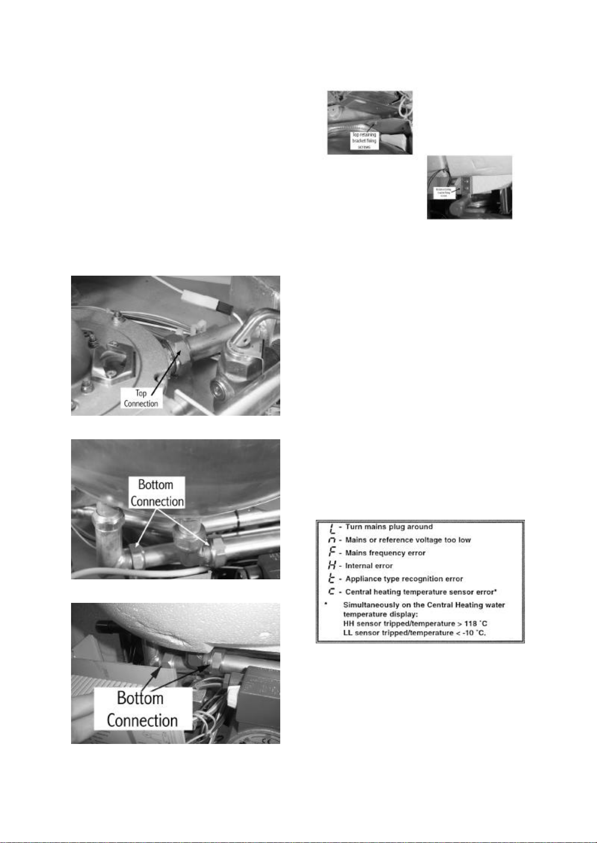
q Temperature & pressure relief valve
q Boiler control unit
q Pump, and;
q Font section of insulation shell.
Disconnect the top water connection (fig 50) and
bottom water connections to the tank. (fig 51 & 52)
Disconnect and remove the tank's top and bottom
retaining brackets by releasing their fixing screws
situated on both sides of the tank. (fig 53)
Remove hot water tank and fit replacement in
reverse order.
Figure 50
Figure 51
Figure 53
12. Malfunctions.
A malfunction can be caused by the failure of the
central heating inst allation or appliance to function
correctly.
The Atmos Multi has three types of malfunctions
that can be reported via the diagnostic display,
being.:
§ Warning report
§ Block report
§ Malfunction report
q Warning report. A letter appearing on the
diagnostic display for 1second in every 5 identifies
a warning report. The appliance continues to
operate, but the function to which the report relates
will be shut down or ignored. (fig 54)
Figure 54: Warning report
Figure 52
q Block report . A block is an error that occurs,
but which does not cause the appliance to shut
down. The appliance waits until the block has been
resolved and then continues to operate normally. A
permanently lit letter on the diagnostic display
indicates a block. (fig 55)
ATMOS MULTI version 2002 Page 42
Page 43

Figure 55: Block report
q Malfunction reports. A malfunction is an error
that occurs causing the appliance to be shut down
by the control unit and locked. The appliance can
only be unlocked by pressing the reset button. A
flashing number or letter on the diagnostic display
indicates a malfunction. (fig 56)
Figure 56: Malfunction report
On resolving a malfunction press the reset button
once. If the appliance does not unlock, press the
reset button again after approximately 15 seconds. If
the malfunction persists, consult the Atmos Multi
Service Manual
ATMOS MULTI version 2002 Page 43
 Loading...