

Page 1
English
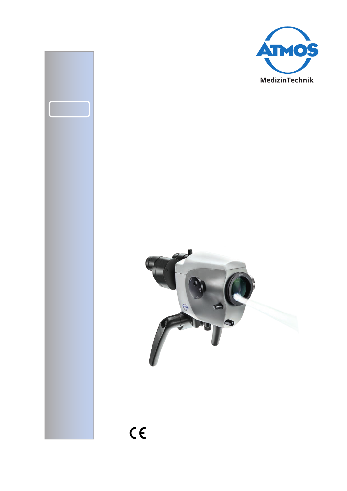
ATMOS® i View
COLPO
Operating Instructions
GA1GB.420101.0
2018-04 Index 24
Page 2

Table of contents
1.0 Introduction .........................................................3
1.1 Notes on operating instructions ............................3
1.2 Intended use .........................................................4
1.3 Function ................................................................5
1.4 Explanation of pictures and symbols ....................6
1.5 Scope of supply ................................................... 7
1.6 Transport and storage ...........................................7
2.0 For your safety ....................................................8
3.0 Setting up and starting up .................................9
3.1 Overview .............................................................. 9
3.2 Setting up ............................................................10
3.2.1 Connection to the mains supply ..........................10
3.2.2 Microscope overview ..........................................10
3.2.3 Operating elements at the colposcope ...............11
3.2.4 Rear view of the control device of the
ATMOS
3.2.5 Rear view of the control device of the
ATMOS
(not with an integrated HD camera) .................... 11
3.2.6 Rear view of the control device of the ATMOS
View 31 COLPO with an integrated HD camera .12
3.3 Integration possibilities........................................12
3.4 Starting up...........................................................13
3.5 Operation requirements ......................................13
3.6 Starting up at a glance ........................................14
®
i View 21 COLPO ................................. 11
®
i View 31 COLPO
®
i
4.0 Operation ...........................................................15
4.1 Colposcope suspension ......................................15
4.2 Mechanical arm...................................................15
4.3 Hand grips...........................................................15
4.3.1 T-hand grip ..........................................................15
4.3.2 Lateral double hand grip .....................................15
4.4 Adjusting the interocular distance .......................16
4.5 Adjusting the eye pieces .....................................16
4.6 Exchanging the lenses ........................................17
4.7 Exchanging the lenses with manual ne
focusing...............................................................17
4.8 Exchanging the VarioFocus lens .........................17
4.9 Adjustment of the 5 fold magnication changer ..17
4.10 Focussing............................................................18
4.10.1 Fine focussing .....................................................18
4.11 Exchanging the binocular tube............................18
4.12 Pivoting green lter .............................................18
4.13 Pivoting H.A.S.I. lter ..........................................19
4.14 Shadowless illumination......................................19
4.15 Colposcope zoom and object eld size...............19
4.16 Measuring scale ..................................................19
4.17 Image and video recording .................................20
4.17.1 Adjusting the light mode of the integrated HD
camera ................................................................20
4.18 Endoscope adapter .............................................21
4.19 HD adapter..........................................................21
5.0 Cleaning and care .............................................22
5.1 Basic instructions ................................................22
5.2 Cleaning the mechanical microscope surface ....22
5.3 Cleaning of lenses / eyepieces ...........................22
5.3.1 Cleaning optical surfaces ....................................22
5.3.2 Optical surface of the endoscope port ................22
5.3.3 Fogging of optical surfaces .................................23
5.4 Recommended surface disinfectants ..................23
5.5 Hygiene plan .......................................................23
Further information, accessories, consumables and spare parts
are available from:
ATMOS
MedizinTechnik GmbH & Co. KG
Ludwig-Kegel-Straße 16
79853 Lenzkirch
Germany
Phone +49 7653 689-0
Fax: +49 7653 689-190
+49 7653 689-292 (Service Centre)
atmos@atmosmed.de
www.atmosmed.de
6.0 Maintenance and Service .................................24
6.1 Basic instructions ................................................24
6.2 Sending in the device..........................................24
6.3 Exchange of spare parts .....................................24
7.0 Troubleshooting ................................................25
8.0 Accessories and Options .................................26
9.0 Technical data ...................................................27
10.0 Disposal .............................................................28
11.0 Notes on EMC ....................................................29
2
Page 3
1.0 Introduction
1.1 Notes on Operating Instructions
These operating instructions contain important notes on how to operate the ATMOS® i View COLPO safely,
correctly and effectively. Their reading helps to avoid risks, and also to reduce repair costs and down-times.
This increases, amongst other things, the reliability and service-life of the colposcope.
These operating instructions serve not only for new operating personnel to be instructed in its use, but also
for use as a reference manual. Reprints (also in extracts) only with permission in written form by ATMOS.
These operating instructions must always be kept available near the colposcope.
Care and safety inspections in conjunction with professional execution provide for operational safety and
readiness for use of your ATMOS
®
i View COLPO and are therefore a must besides regular cleaning.
Repair work and safety inspections may be carried out only by expert personnel authorised by ATMOS. By
applying only original spare parts you will have the guarantee that operational safety, readiness for work
and the value of your ATMOS
• The product ATMOS
®
i View COLPO will be preserved.
®
i View COLPO bears CE marking CE according to the EC Directive of the council
for medical products 93/42/EEC and meets the basic requirements of Appendix I of the directive.
®
• The product ATMOS
i View COLPO complies with all applicable requirements of the Directive 2011/65/
EC restricting the use of certain hazardous substances in electrical and electronic equipment (“RoHS”).
• The declaration of conformity and our general standard terms and conditions can be obtained on our
website at www.atmosmed.com.
• The quality management system applied at ATMOS has been certied according to international
standards EN ISO 13485.
• Prior to start-up please peruse chapter 2.0 „For your safety“, in order to be prepared for any possible
dangerous situations.
These operating instructions are valid for the following
devices:
®
ATMOS
i View 21 COLPO .........................REF 605.0000.0
Colposcope with an integrated, fanless, high transmission,
high performance LED light in the colposcope head
®
ATMOS
i View 31 COLPO .........................REF 606.0000.0
Colposcope with an integrated, fanless, high transmission,
high performance LED light in the colposcope head
Please keep this document for future consultation!
3
Page 4

1.0 Introduction
1.2 Intended use
Name: ATMOS® i View 21 COLPO
®
ATMOS
Main functions: Visualization of natural body orices (genital area) for examinatory purposes
i View 31 COLPO
Medical indications /
application:
Specication of the main
function:
User prole: Examinations and surgical interventions which are carried out using the
Patient groups: No restrictions
Application organ: Natural orices (portio and vulva)
Application time: Short-term, under normal conditions for permanent use over a maximum up to
Application site: Application sites are hospitals, doctor’s ofces, ORs at gynaecologists. The
Standard gynaecological examinations. Visual control of the genital area.
The application organ is illuminated for examination purposes and can be
visualized on a monitor if desired by an integrated, fanless high transmission,
high performance LED light source, 5 fold magnication changer, integrated
camera module, pivoting green lter and an automatic light control via tilt
sensor; the light output is min. 120 kLux (200 mm)with a colour temperature of
5.500 K ± 10%.
colposcope may only be performed by doctors with appropriate training.
Only qualied personal with a proper hygiene training may prepare the
colposcope for surgical interventions.
Installation and maintenance may only be carried out by service technicians
who were trained and authorised by the manufacturer.
30 days
examination with the colposcope may only be executed by medically trained
persons.
The colposcope may only be used in closed rooms, on rm ground or mounted
to the ATMOS
In ORs an appropriate protective sleeve must be used.
®
Chair 41 Gyne .
Contraindications: • No application in ophthalmology.
The product is: active
Sterility: The colposcope is not a sterile product.
Single-use product /
reprocessing:
The colposcope is intended for multiple use. The device and parts of the
accessories are reusable. For information on reprocessing, cleaning and
disinfection please see the operating instructions.
4
Page 5

1.0 Introduction
1.3 Function
The ATMOS® i View COLPO is a complete colposcope system, consisting of optics and lighting. It produces outstanding pictures for
examination purposes with the use of latest LED technology and patent registered optics. The interaction between the integrated
fanless, high transmission, high performance LED, the apochromatic optics and the precisely tting options offer best working
quality.
The ergonomically assorted buttons, two selectable hand grips and the integrated control panel provides the user with highest
level of ergonomic comfort and suitability for daily use as well as an outstanding and intuitive handling. Via the control panel the
individual options of the ATMOS
/ stopping of possible video sequences, the operator is capable of manually switching the LED light source on and off despite
the activated automatic light control. Due to the variety of options which the ATMOS
position to congure a colposcope to suit his requirements. The following functions can be chosen optionally:
• 4 lenses with different focal distances (200, 250, 300 and 400 mm) with or without ne focussing or a VarioFocus 200-350 mm
(easy exchange of the lenses due to the respective thread on the colposcope head)
• 5 fold magnication changer. Exact adjustments due to turning disks on both sides.
• Binocular tubes, simple adaption due to the Zeiss dove tail.
• Pivoting colour lter
• Measuring scale
• Shadowless illumination
®
i View COLPO can be activated. Besides the triggering of the camera (freeze frame) and starting
®
i View COLPO has to offer, the user is in a
Due to the LED light source and the integrable camera solution (SD integrated respectively as HD or endoscope adapter for the
connection of an external camera) the ATMOS
In connection with the mechanical support arm and the numerous connection possibilities to units and stands the ATMOS
®
i View COLPO is a guarantor for best image quality.
®
i View
COLPO offers countless system possibilities, which can be individually adapted to suit the users environment!
®
These operating instructions describe all functions with a maximum conguration of the ATMOS
i View 31 COLPO.
5
Page 6
1.0 Introduction
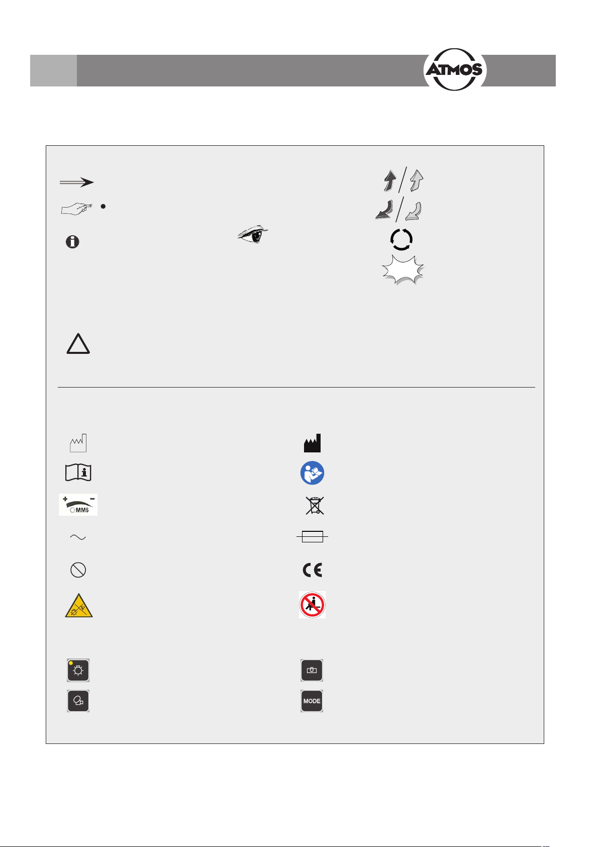
1.4 Explanation of pictures and symbols
Short cuts / symbols contained in these operating instructions
Follow the arrows
■
General information
Move, plug... in this
direction
Please press where
dot indicates
Please read,
important information
Graphic symbols contained in these operating instructions
Warning, special diligent notice
●
Numeration
Check
!
Symbols ATMOS
SN Serial number
®
i View
Manufacturing date Manufacturer
Observe operating instructions! Observe operating instructions!
REF
click
) Important information
Order number
Turn, shift... in this
direction
Replace
Engage, check
correct t
Weight adjustment for the carrier arm Professional disposal
Alternating current Fuse
2
Control panel buttons
Single use product - not for reuse.
Exchange after use.
Do not look directly into the light source of
the ATMOS
Light on / off (independent of automatic light
control)
Video recording (start / stop)
®
i View COLPO.
This product complies with the relevant
requirements of EU Directives
Sitting is prohibited.
Freeze frame
With an integrated HD camera: Adjusting the light
mode of the camera
6
Page 7
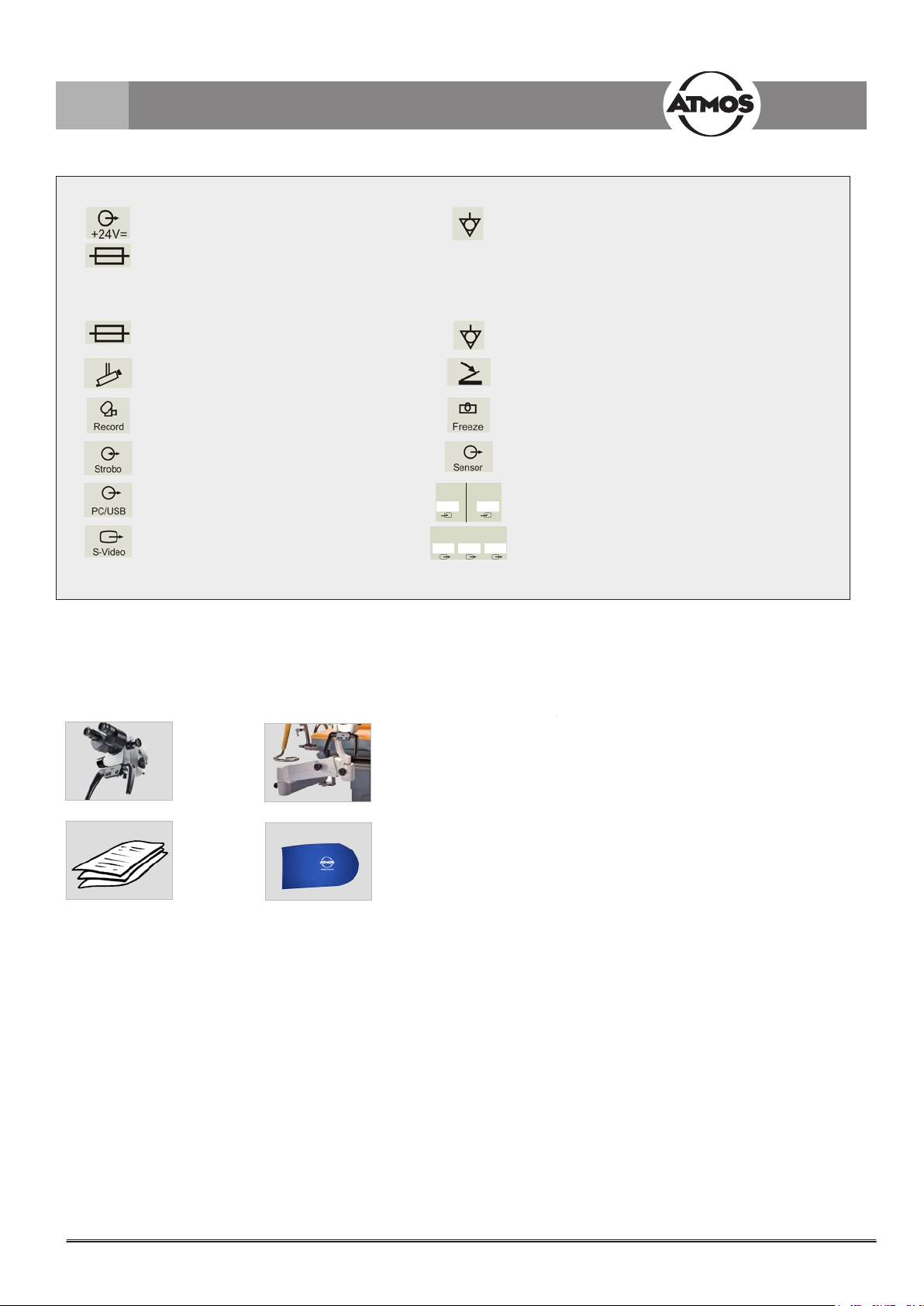
1.0 Introduction
Foot Switch
Out 1
Out 2 Out 3
Video Out
Foot Switch
Only ATMOS® i View 21 COLPO
Output of the power supply for the electronics in the colposcope
Fuse
®
Only ATMOS
i View 31 COLPO
Fuse Potential equalisation acc. to IEC 604175021
Colposcope Foot switch
Record function Freeze
Potential equalisation acc. to IEC 604175021
not in use
USB port
S-video-output (not with an integrated HD
camera)
Video In
Intern 1
Out 1
Video Out
Out 2 Out 3
Output signals of the tilt sensor in the carrier arm
system
Video In
Extern 2
Input video signal internal / external (Only with an
integrated HD camera)
Output video signal
(Only with an integrated HD camera)
1.5 Scope of supply
• Prior to dispatch, the ATMOS® i View COLPO was subjected to an extensive functional test and was carefully packed.
Nevertheless, please compare the contents of the shipment on completeness immediately upon receipt (see delivery note).
Colposcope
Operating
Instructions
Colposcope arm
Protective cover
1.6 Transport and storage
• After the transport of the ATMOS® i View in
temperatures below 0°C or prior to rst start up
it should be kept at room temperature for at least
six hours. If the ATMOS
acclimatized it may not be used as damages to the
electronic components may be the result.
Only transport the device in a shipping carton, which is
padded and offers sufcient protection.
If damage occurs during transport:
• Document and report the transport damage.
• Send the device to ATMOS (Chapter „6.2 Sending in
the device“ on page 24).
®
i View COLPO is not
Ambient conditions:
• Transport / storage:
-10...+50 °C;
30...95 % humidity without condensing
air pressure 500...1060 hPa
• Operation:
+10...+35 °C;
30...95 % humidity without condensing
air pressure 700...1060 hPa
7
Page 8
2.0 For your safety
!
For your safety
• To safely disconnect the unit from the mains, the power
cord must be removed from the IEC connector of the
control device!
®
• The ATMOS
with IEC 60601-1-1/EN60601-1 and it is a device with
protection class I. In order to avoid the risk of electrical
shock, this unit may only be connected to a mains supply
with properly installed earth conductor.
• Power cables, accessories and access cables need to be
checked for defects prior to setting up the ATMOS
COLPO. Damaged cables must be replaced immediately.
• The ATMOS
qualied personnel.
• The ATMOS
in an explosion-hazardous environment. Explosion-
hazardous areas may be caused by the use of ammable
anaesthetics, skin cleansing products and skin
disinfectants.
• If uids penetrated the ATMOS
be sent in and may only be used after the check up of an
ATMOS authorised person.
• After the transport of the ATMOS
below 0°C or prior to rst start up it should be kept at room
temperature for at least six hours. If the ATMOS
COLPO is not acclimatised it may not be used.
• Do not plug in electric connections (plug, socket) under
the use of force. If this is not possible check whether the
plug ts the socket. If you should ascertain a defect in the
connection you should have it repaired by our service.
• Never look straight into the sun with lenses or eye lenses.
• Always make sure that you do not blind patients with the
light source! Watch out that patients do not look directly into
the light source!
Never look directly into the light source!
> Damage to the eyes due to the strong glare.
• Please pay attention to the period tests in chapter 6
„Service and maintenance“ on page 24.
• Prior to every use the colposcope suspension (all joints
included) need to be checked for safe connections.
• Take care that the patient does not touch the device or
have any contact with it.
• Please observe the EMC Directives. Failure to follow this
guideline can result in a hazard.
• Make sure that the unit is positioned so that all the controls
and the on/off switch are always accessible.
• Dispose of wrappings accordingly.
• Before connecting the ATMOS
be checked whether the requested mains voltage of the
ATMOS
mains power supply.
• Only proper and undamaged plugs and extension cables
may be used.
i View COLPO is a device designed in line
®
i View
®
i View COLPO may only be operated by
®
i View COLPO is not designed to be used
®
i View COLPO it needs to
®
i View in temperatures
®
i View
®
i View COLPO it needs to
®
i View COLPO matches the mains voltage of the
• To disconnect the ATMOS
mains supply, rst remove the plug from the wall outlet.
Disconnect the connection line on the ATMOS
®
i View COLPO from the
®
i View
COLPO afterwards only. Never touch plug or line with wet
hands.
• Please observe the ambient conditions stated in the
technical data (chapter 9.0).
®
• The ATMOS
i View COLPO meets the immunity to
interference requirements of IEC 60601-1-2 / EN 606011-2 „Electromagnetic Compatibility – Medical Electrical
Devices“.
• ATMOS is not liable for personal injury and damage to
property if
- no original ATMOS parts are being used,
- the advice for use in these operating instructions is
not being observed,
- assembly, new settings, alterations, extensions
and repairs have been carried out by personnel not
authorised by ATMOS.
• Unplug the device immediately if you observe fumes,
sparks or weird noises.
• With every light source a warming of tissue due to
absorption may occur. Please make sure to reduce
duration of use to a minimum, to switch off the light
source when not in use and to check heat development
if necessary.
®
• The ATMOS
i View COLPO may be operated only
in rooms used for medical purposes, but not in areas
subject to explosion hazards and in oxygen rich
environments.
• Take into consideration, when setting up the colposcope,
that the elastic force of the arm – without colposcope
head – is exceedingly strong. Operate the break of the
height adjustment carefully.
• Risk of injury! Take care not to roll the mobile stand over
your feet when moving the stand.
• Please note that only PCs and monitors with IEC 6060101/EN 60601-1 approval may be connected to the video
outlet of the ATMOS
®
i View COLPO supply module!
• During operation, the user is obliged to regularly check
the microscope for proper function. In the unlikely
event of failure of the microscope, the user must take
precautions to continue the treatment of the patient with
suitable methods.
8
Page 9
3.0 Setting up and starting up
3.1 Overview
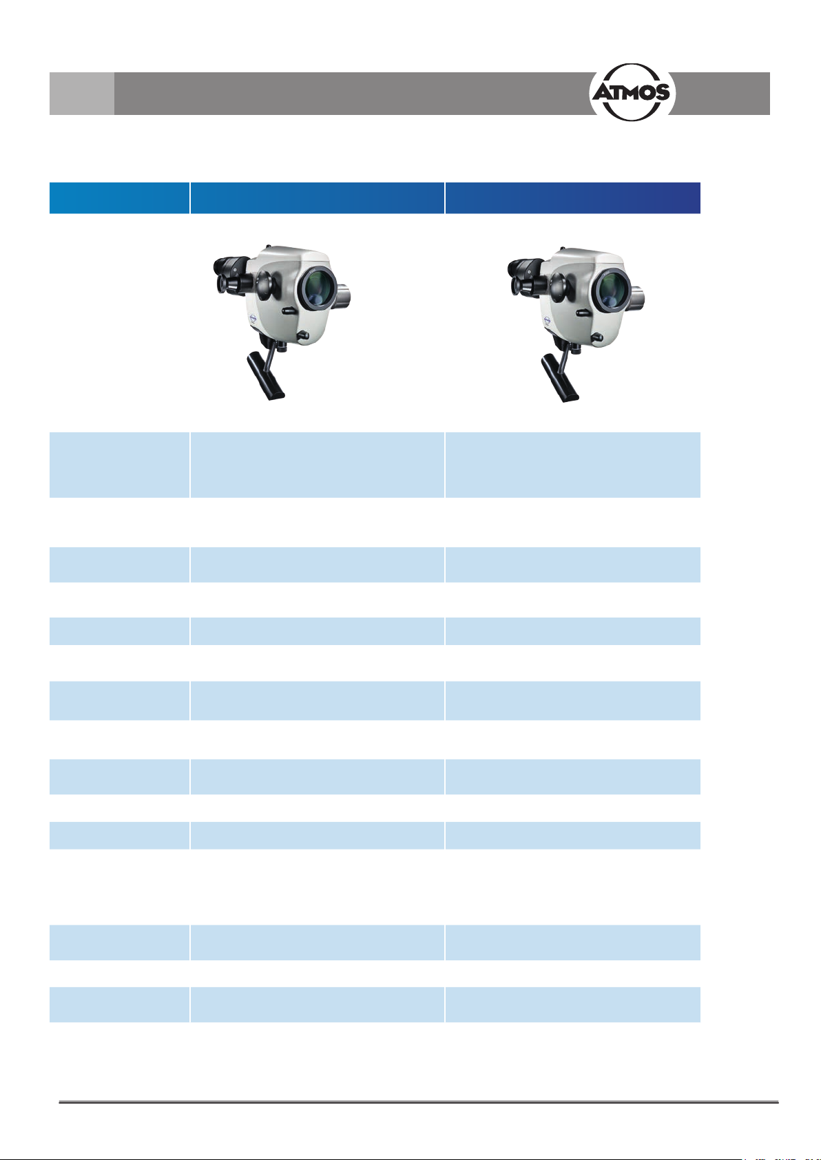
ATMOS® i View 21 COLPO ATMOS® i View 31 COLPO
Examination colposcope with an inte-
Description
Integrated high
performance white
light LED
Automatic light
control
Optimised stereo
effect
Measuring scale Optional Optional
Integrated operating
panel
Colour lter Optional
Integrated camera -
HD adapter for an
external camera
Endoscope adapter - Optional
Mains voltage 100–240 V 100–240 V
grated, fanless, high transmission, high
performance LED light in the colposcope
head
Optional Optional
- Optional
Examination colposcope with an integrated, fanless, high transmission, high
performance LED light in the colposcope
head
Optional green lter or
Optional H.A.S.I. lter
Optional SD camera or
Optional HD camera
min. 120 kLux (200 mm)
Light output
Operating life of the
LED
Colour temperature 5.500 K ± 10 % 5.500 K ± 10 %
Scope of delivery
min. 80 kLux (250mm)
min. 55 kLux (300 mm)
min. 30 kLux (400 mm)
50 000 hours 50 000 hours
Dust cover,
operating instructions
min. 120 kLux (200 mm)
min. 80 kLux (250mm)
min. 55 kLux (300 mm)
min. 30 kLux (400 mm)
Dust cover,
operating instructions
9
Page 10
3.0 Setting up and starting up
3.2 Assembly
Please make sure that the static conditions stated by ATMOS MedizinTechnik are met (for details see the separately enclosed
!
document „Static requirements for installing the ATMOS i View“). The fullment of these requirements must be conrmed by an
authorized expert.
Mains voltage and fuse: Mains voltage: 100-240 V; 50/ 60 Hz, fuse: 2 x T 3.15 A
Please note that only PCs and monitors with IEC 606010-1/EN 60601-1 approval may be connected to the video outlet of the
ATMOS
3.2.1 Connection to the mains supply
Potential equalisation:
The ATMOS
potential equalisation rail in the room if need be. Hereby user/patient safety can be increased especially in the case of a defective
earth conductor. For connecting the device's potential equalisation plug with the potential equalisation rail of the room, use the
potential equalisation cord with REF 530.0030.0.
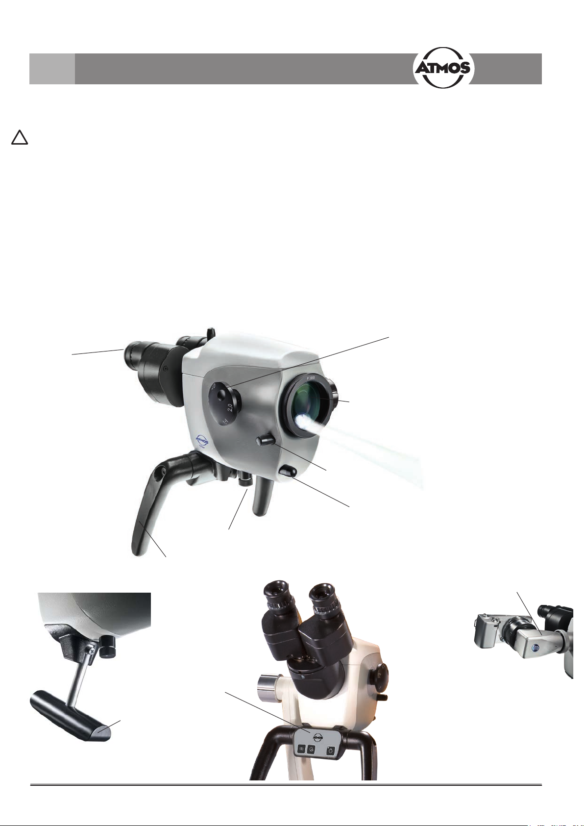
3.2.2 Microscope overview
®
i View COLPO supply module!
®
i View COLPO supply module has a rear connection for potential equalisation which can be connected to the
Wide eld eye
piece lenses with
binocular tube
Rotating disk 5
fold magnication
changer
Lens
Lateral double hand
grip (optional)
T-hand grip
(optional)
Pivoting colour lter
(optional)
Measuring scale
(optional)
Brightness control
HD adapter for SONY
digital camera (optional)
Control panel
(optional)
10
Page 11

3.0 Setting up and starting up
3.2.3 Operating elements at the colposcope
LED
STROBO
AFD
MODE
Light on / off
(independent of
Freeze
frame
Video recording
(start / stop)
With an integrated
HD camera:
Adjusting the light
mode of the camera
automatic light
control)
3.2.4 Rear view of the control device of the ATMOS® i View 21 COLPO
Output of the power supply
for the electronics in the
colposcope
Connection for potential
equalization performance acc.
to IEC 60417-5021
IEC power plug with fuse inlay
for the connection to the mains
power supply
3.2.5 Rear view of the control device of the ATMOS
Output signal of
the „Video record
function“
USB port for the
transfer of the key
status of the „Freeze
frame “- and „Video
recording -functions“.
Output signals of
the tilt sensor in the
carrier arm system
Output signal of
the „Freeze frame
function“
S-Video-output of
the integrated SD
camera
not in use
®
i View 31 COLPO (not with an integrated HD camera)
Connection for potential
equalization performance acc.
to IEC 60417-5021
Connection for
the supply to
the colposcope
electronics and
control line
Connection to the foot
switch for switching
between the light
channels
IEC power plug with fuse
inlay for the connection
to the mains power
supply
11
Page 12

3.0 Setting up and starting up
3.2.6 Rear view of the control device of the ATMOS® i View 31 COLPO with an integrated HD camera
HD video input. Can
only be used for the HD
camera module
Connection for
the supply to
the colposcope
electronics and
control line
Video In
Intern 1
Microscope
not in use
HD video input from
an external HD
video source
Video In
Extern 2
Strobo
Sensor
Output signals of
the tilt sensor in the
carrier arm system
HD video outlet from the
video source internal 1 or
external 2
Video Out
Out 1
Freeze
Record
Output signal
of the „Video
record function“
Out 2 Out 3
PC/USB
Output signal of
the „Freeze frame
function“
Connection to the foot
switch for switching
between the light
channels
Foot Switch
100 - 240V~
2 x T 3,15A
PC connection
(optional)
IEC power plug with fuse
inlay for the connection
to the mains power
supply
Connection for
potential equalization
performance acc. to IEC
60417-5021
3.3 Integration options
Please note the assembly instructions for the integration options.
®
ATMOS
For the integration into ATMOS
Please note that a save combination of the ATMOS
guaranteed with the ATMOS
Mobile stand
When moving the roller stand please make sure that the colposcope arm is in a retracted position and the screws are tightened.
Risk of injury! Take care not to roll the mobile stand over your feet when moving the stand.
!
When the device is placed in the working position the brakes must be locked.
Chair 41 Gyne
®
Chair 41 Gyne.
®
Chair 41 Gyne.
®
i View COLPO can only be
12
Page 13

3.0 Setting up and starting up
3.4 Starting up
• Remove the colposcope from the packaging. Check whether the mains current on the type label corresponds to the mains
power supply.
• Peruse safety information in part 2.0 prior to starting up the device for the rst time.
• Check the scope of delivery.
• After the transport of the colposcope in temperatures below 0°C it must be kept at room temperature for at least six hours. If
the colposcope is not acclimatized it must not be used.
• Take into consideration, when setting up the colposcope, that the elastic force of the arm – without colposcope head – is
exceedingly strong. Operate the break of the height adjustment carefully.
®
• To activate the ATMOS
3.5 Operating requirements
Please note that the following requirements must be adhered to for further application after the installation of the device:
• All joints and connection parts which are responsible for the safety of the device are securely fastened.
• All electronic connections (cables, plugs, power cables etc.) are in good order and condition.
• The specied mains voltage and frequency on the colposcope corresponds to the supply network.
• The colposcope is connected to a safety connection socket with the provided mains cable.
• Attention, never point or direct the beam into the patients eyes. Do not look directly into the light source.
!
• With every light source a warming of tissue due to radiation and absorption could occur. This could result
in damage to the biological tissue. Please keep the luminosity and duration of use to a minimum. Switch
off the light source when not in use and check the heat development if necessary.
i View COLPO please use the power switch on the front side of the control device.
13
Page 14

3.0 Setting up and starting up
3.6 Starting up at a glance
Adjust colposcope to initial position on the colposcope suspension by use of the xing wheel.
Adjust colposcope horizontally and vertically.
Adjust all the clamps on the carrier and oat arm to secure the movability of the arm in compliance with the
requirements.
Swing in colposcope into the working space.
Adjust the interocular distance by pressing or pulling the lens tubes together or apart. The interocular distance is
perfectly adjusted when you look through and a circular picture is perceived!
Adjusting the eyepieces.
Persons without glasses Persons with glasses
Eyepieces remain in initial
position (eyepieces are pulled
out). Dioptre scale adjusted to
zero
People with defective vision
and glasses
Keep glasses on, push
eyepieces in direction of the
lens tube until they engage
audibly. Adjust dioptre scale
to zero.
People with defective
vision without glasses
(refraction values known)
Remove glasses and adjust
dioptre scale to matching
number (eyepieces are
pulled out).
People with defective
vision without glasses
(refraction values
unknown)
Remove glasses and adjust
both eyepieces to +5 dpt.
Remove the lens tube from
the colposcope head and
focus on an object* in the
distance. The object still
looks blurred. Turn the
dioptre ring of the rst
eyepiece slowly in clockwise
direction until the object
is sharp. Keep your other
eye closed while adjusting
the eyepiece. Repeat this
procedure for a couple
of times to determine an
average value. Adjust
the second eyepiece by
the same procedure and
reattach the lens tubes to the
colposcope head with the
connective screw (eyepieces
are pulled out).
* Never use the sun as an
object!
14
Set the 5-fold magnication changer unit to maximum zoom (2.0). Approach the object with the colposcope
(according to the chosen focal distance) until the image is sharp. If the zoom level is changed the grade of
sharpness is retained.
Brightness can be adjusted by the rotary knob on the bottom of the device if necessary.
Page 15

4.0 Operation
Rotating
knob
4.1 Colposcope suspension
By means of a corresponding suspension the colposcope
head is connected laterally to the colposcope arm. The
complete range of cables run through the suspension therefore no disturbing cables are visible from the outside
(with the exception of the connection to the HD adapter
and direct connection to a monitor). Due to a rotating
knob, which is situated on the side of the suspension, the
colposcope can be adjusted vertically to suit the individual
requirements of the user.
To x the colposcope head turn the rotating knob towards
you in a clockwise direction.
To loosen the colposcope head turn the rotating knob
towards you counter-clockwise.
Attention: Check the secure connection of the colposcope
to the suspension prior to every use!
4.2 Mechanical arm
The mechanical colposcope arm can be adjusted via four
set screws according to the individual requirements of the
user. Choose the strength of the clamping so that the free
movement of the arm suits your requirements. Turn the
set screw in clockwise direction to x the arm. To loosen
the arm turn counter-clockwise. To align the arm please
observe the assembly instructions for the integration
possibilities.
Attention: Prior to use ensure that the brakes of the
support arm are set correctly.
Automatic light switching: Once the arm is in the lower
position the LED light switches off automatically.
Adjusting screws
4.3 Hand grips
When purchasing the ATMOS® i View COLPO you may
choose between two versions of handles.
4.3.1 T-hand grip
(see gure)
4.3.2 Lateral double hand grip
The position of the lateral double hand grip can be gradually
adjusted by simultaneously pulling and turning the handle.
15
Page 16
4.0 Operation
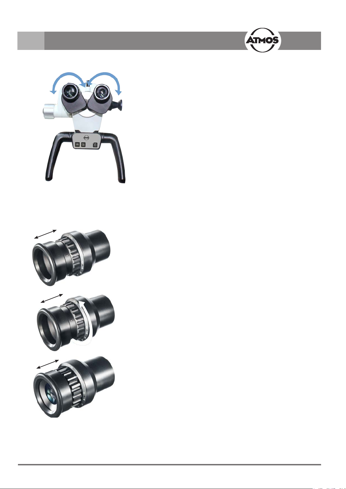
4.4 Adjusting the interocular distance
The interocular distance is adjustable between 50-75 mm.
• Swivel the colposcope into the work space.
• Look through the eye lenses and push or pull the eye
lens tubes together or apart with both hands.
The interocular distance is perfectly adjusted when you
look through with both eyes and a circular eld is visible!
4.5 Adjusting the eye pieces
Persons without glasses:
• Eyepieces remain in initial position. Initial position =
The eye steerings of the eyepieces are pulled out.
• Make sure that the zero of the dioptre scale complies
with the index on the eyepieces.
Persons with glasses:
• People with defective vision and glasses keep their
glasses on and push the eyepieces in direction of the
lens tube until they engage audibly. Adjust dioptre scale
to zero.
• People with defective vision (with known refraction
values) should take their glasses off and adjust the
dioptre scale on the eyepieces to the matching number
(the eye steerings of the eyepieces are pulled out).
The process of focussing is performed as described in
Chapter 4.9.
• People with defective vision without glasses adjust both
eyepieces to +5 dpt. Remove the binocular tube and
the eyepiece from the microscope head and focus on
a distant object*. The object still looks blurred. Slowly
turn the dioptre ring of the rst eyepiece in clockwise
direction until the object is sharp. The other eye must
remain closed. Repeat this procedure for a couple
of times in order to determine on an average value.
Adjust the second eyepiece by the same procedure.
Reattach the lens tubes to the microscope head with
the connective screw. The process of focussing is
performed as described in Chapter 4.10.
* Never use the sun as an object!
16
Page 17

4.0 Operation
4.6 Exchanging the lenses
The designated thread on the colposcope head allows
for easy exchange and xation of the different lenses.
Due to the integrated screw mount lenses can be
loosened by turning it to the left hand side and xated by
turning it to the right.
Grub screw
Lens
Setting dial
4.7 Exchanging the lenses with
manual ne focussing
Mount lens as described above and secure it with the
intermediate screwed ring.
4.8 Exchanging the VarioFocus lens
To loosen the VarioFocus lens from the colposcope
head, turn it to the left. To tighten the VarioFocus lens on
the colposcope head, turn it to the right onto the thread.
Position the setting dial
The dial can be positioned on either side of the
VarioFocus lens.
Attention! During the process rmly hold the VarioFocus
lens just in case it may loosen itself from the colposcope
head and fall off.
Loosen the three grub screws on the lens. Continue
to hold the lens and turn the setting dial in the desired
position. Tighten the three grub screws.
4.9 Adjusting the 5-fold magnication
changer
The 5-fold magnication changer from ATMOS enables
free range zoom between 0.5x up to 2.0x.
• Select the desired zoom factor by selecting one of the
lateral rotating knobs.
• Pay attention that the chosen zoom factor engages
audibly with the groove.
• Freely adjustable zoom factors: 2.0 - 1.4 - 1.0 - 0.7 -
0.5.
• The magnication which points in the direction of the
eyepieces is the current magnication.
17
Page 18

4.0 Operation
Fine focussing
4.10 Focussing
• Adjust the zoom to maximum (2.0) on the magnication
unit.
• Approach the object with the colposcope until the
image is sharp.
• If the zoom level is changed the pre-adjusted degree of
sharpness is still maintained.
4.10.1 Fine-focussing
The optional ne focussing allows for sensitive and
precise focussing in a 17 mm range. Fine focussing is
necessary in order to focus accurately while zooming in.
• Replace the mounted lens with the appropriate lens
for ne focussing (simple mounting due to the screw
mount at the colposcope head. Secure with the
intermediate screwed ring).
• Conduct the focussing as described above.
• Adjust focus by use of the lateral adjusting disk.
Binocular straight lens tube
Binocular angled lens tube 45°
Undo screw
Undo screw
4.11 Exchanging the binocular tube
The tubes focal distance of 160 mm allows for a
comfortable and fatigue-proof observation of the object
with both eyes. Working is made easier due to the
exceptionally large exit pupil and an increased stereo
base of 24 mm.
Please hold the lens tube with one hand while loosening
the screw. Otherwise the lens tube could drop.
• Loosen the screw on top of the lens tube and remove
the tubes from the colposcope head.
• Make sure that the gudgeons and grooves of the dove
tail xation engage and the tubes lie at.
• Tighten the screw again.
• Check for a secure t.
4.12 Pivoting green lter
The pivoting colour lter enhances contrast of the
microscopic picture for better visibility of vessel structures.
• Turn the function knob by 90° in clockwise direction to
swing in the lter.
• By turning the knob by 90° in an anti-clockwise
direction the lter is removed from the optical beam
path of the colposcope.
18
Pivoting green lter
Page 19

4.0 Operation
4.13 Pivoting H.A.S.I. lter
The pivoting H.A.S.I. lter gives a more contrasting and
clearer view of the mucosa.
• Turn the function knob by 90° in clockwise direction to
swing in the lter.
Pivoting H.A.S.I.
lter
4.14 Shadowless illumination
The option shadowless illumination prevents instruments from causing shadows in the eld of view. This option cannot be
retrotted.
• For the shadowless illumination no operating steps are required.
4.15 Colposcope zoom and object eld size
• By turning the knob by 90° in an anti-clockwise
direction the lter is removed from the optical beam
path of the colposcope.
Lens f in mm
equals the
approximate
working
distance
200 6.4 / 31 9 / 22 12.8 / 16 18 / 11 25.6 / 8 16 x
250 5.1 / 39 7.2 / 28 10.2 / 20 14.3 / 14 20.5 / 10 16 x
300 4.3 / 47 6 / 33 8.5 / 23 12 / 17 17 / 12 16 x
400 3.2 / 62 4.5 / 44 6.4 / 32 9 / 22 12.8 / 16 16 x
* Read off at factor 1 when using the colposcope zoom without the zoom unit.
0.5 0.7 1* 1.4 2.0
4.16 Measuring scale
Measuring scale Figure not true to scale
Factor display on the magnication unit Eyepieces with
Total zoom / visual eld Ø in mm
20 mm
10 mm
0.75 mm 2 mm
lens tubes
f = 160 mm
5 mm
7 mm
10 mm
This gure is for guidance
only and may not be used
for measuring absolute
quantities.
Via a small turning knob beneath the lens a true to scale dimension scale can be faded into the eld of the illumination light path.
This documentation display enables the measurement of objects regardless of the selected magnication. The scale will be
displayed in both the 3D picture and on all camera pictures and if required it can be faded out at any time.
• To fade-in the scale turn the knob by 45° in a clockwise direction.
• Via a 45° rotation in anti-clockwise direction the scale can be faded out from the path of illumination.
The following measures have to be observed: - Distance 2 mm, - Line width 0.75 mm
Please note that these specications are only correct for the following combination: Measuring scale for 300 mm lenses, 300 mm
lenses with or without ne focusing or wide angle eyepieces 16 x.
19
Page 20

4.0 Operation
4.17 Image and video recording
LED
STROBO
AFD
MODE
Integrated camera: If desired an SD camera or a HD
camera can be integrated in the ATMOS
External video sources: External video sources can be
controlled via the panel buttons if they are connected to the
jack plugs “Freeze” and “Record”.
Control panel buttons:
Save image.
Start / stop the recording of a video frequency
Adjusting the light mode of the integrated HD camera.
The data are transmitted to a connected PC (USB interface).
The ATMOSoft software can process the data.
Only with an integrated HD camera
You can change between the integrated HD camera and
external video source by switching the LED light on or off.
As soon as the LED light goes off the integrated camera is
switched off and the data from the external video source is
displayed (Video Out 1 - 3).
Also observe this within the automatic light switching.
®
i View 31 COLPO.
4.17.1 Adjusting the light mode of the integrated
HD camera
By pressing the MODE button once the current light mode
of the integrated HD camera is displayed on the monitor.
By pressing the MODE button again the light mode can be
changed.
Light mode Display on the monitor
Standard LED light remains unchanged.
When the power is switched on, the default
setting is automatically selected.
Center LED light will be displayed with less
reections.
Suitable for recordings through a speculum.
Warm LED light appears warmer.
20
Page 21

4.0 Operation
4.18 Endoscope adapter
The standardized endoscope adapter allows for an easy
connection to an external ATMOS Cam or other external
endoscope or digital camera (third party products). The
ATMOS Cam can be easily and swiftly attached to the
endoscope adapter by means of a special clip seal.
Other endoscope cameras which provide a standardised
connection interface can also be adapted without any trouble.
To attach an external digital camera a special adapter (which
is suitable for the respective digital camera) is required.
4.19 HD adapter
Due to the especially developed HD adapter it is possible to
connect a SONY digital camera with e-mount bayonet to your
ATMOS
archive HD resolution pictures.
At dispatch the HD adapter is covered with a cover cap. This
cap is to protect against contamination and has to be reattached at any time e.g. if the camera is removed or when
the adapter is unused.
®
i View Colpo. This camera enables you to take and
Please make sure that externally connected cameras do not
exceed a weight of 300 g.
21
Page 22

5.0 Cleaning and care
5.1 General information on cleaning and disinfection
Prior to cleaning
Medical devices like the ATMOS® i View COLPO must be fail safe at all times. Therefore we recommend prior to every use:
if
necessary
) The described action relating to cleaning and disinfection
resp. sterilisation do not substitute the relevant instructions
which must be adhered to prior to operation!
• All disinfectants used for the disinfection of the ATMOS
View COLPO must be approved.
®
i
) Always observe the concentration specications and
instructions by the respective manufacturer!
5.2 Cleaning the mechanical colposcope surface
All mechanical surfaces of the ATMOS® i View COLPO must be wiped and disinfected after each application. Do not use
aggressive or abrasive cleansing agents.
Residues can be removed with a mixture made from equal parts of ethyl alcohol and distilled water to which a drop of standard
washing-up liquid is added.
®
If uids penetrated the ATMOS
!
authorised person.
Disconnect the plug from the mains current prior to cleaning and disinfecting the colposcope surface.
!
For a sterile covering of the device the single use sterilization drapes may be used. The sterilization drapes may only be used once.
Afx the cover loosely so that there is enough room left for the colposcope support and the unit. The drapes must be especially
loose around the hand grips as the physician must be able to use the operating elements though the cover.
i View COLPO it needs to be sent in and may only be used after the check up of an ATMOS
5.3 Cleaning of lenses / eyepieces
5.3.1 Cleaning optical surfaces
The multilayer T* coating of optical components (e.g. eyepieces, lenses) results in optimum image quality.
Image quality could be reduced even by the slightest contamination of the optics or by ngerprints. In order to protect the internal
optics from dust, the instrument should never be left without a safety cover, HD adapter, lens, binocular tube or eyepiece installed
when it is not in use.
After use the colposcope should be covered in order to protect it from dust. Always store lenses, eyepieces and accessories which
are not being used in clean, dust-free cases.
The external surfaces of optical components should only be cleaned when required.
• Dust which has accumulated on the optical surfaces can be blown off or removed with a soft, clean brush.
5.3.2 Optical surface of the endoscope connection
The endoscope connection is protected against contamination and humidity by an end glass cover. For cleaning and care of
this glass plate, proceed in the same way as with the other optical surfaces of the ATMOS
following the instructions for cleaning optical surfaces.
On delivery the endoscope connection is protected with a cover against contamination and humidity.
®
i View COLPO. This can be done by
22
Page 23

5.0 Cleaning and care
5.3.3 Fogging of optical surfaces
To prevent the eyepiece optics from fogging, we recommend using an anti-fogging agent.
Note:
Anti-fogging agents provided by eyecare professionals for use with eyeglass lenses are also suitable for ATMOS optics.
• Please observe the instructions supplied with each anti-fogging agent.
Anti-fogging agents do not only ensure fog-free optics they also clean and protect them against dirt, grease, dust, uff and
ngerprints.
5.4 Recommended surface disinfectants
When using disinfectants containing aldehyde and amine at the same object colour changes may occur.
• Do not use
- Disinfectants which contain organic or inorganic acids or bases as they could cause corrosion damage.
- Disinfectants which contain chloramines or phenol derivatives as they could cause stress cracks in the material which is used
for the housing.
Suitable for
Disinfectant
Green & Clean SK x x
®
Bacillol
Kohrsolin
30 Foam x
®
FF
(Application concentrate)
®
Kohrsolin
extra
(Application concentrate)
®
Mikrobac
forte
(Application concentrate)
®
Mikrozid
SaniCloth
Sensitive Wipes x x
®
Active x x
Microscope Handle Control unit Other mechanical
surface treatment
x x x
x x x
x x x
Optical surfaces
5.5 Hygiene Plan
WHAT HOW WHEN Details
C D S
Housing X X X Manual wiping and disinfection
Lens / Optics X X X Manual wiping and disinfection
Operation parts* X X X Manual wiping and disinfection
Protective covers
(disposables)
Hand grips X X X Manual wiping and disinfection
C= Cleaning, D= Disinfection, S= Sterilization
* Operation parts
Knobs to adjust (colour lter, 5 fold magnication changer, operator panel, adjusting screws on the arm)
after each
application
daily
X
weekly
monthly
Single-use product -> not for reprocessing, change after use
23
Page 24

6.0 Maintenance and Service
6.1 General advice
• Prior to every use a visual inspection of the colposcope and
colposcope connection line must be performed. Damaged
cables must be replaced immediately!
• Maintenance, repairs and period tests may not be carried
out while the product is used on the patient.
• Maintenance, repairs and period tests may only be
carried out by persons who have the appropriate technical
knowledge and are familiar with the product. To carry out
these measures the person must have the necessary test
devices and original spare parts.
ATMOS recommends: Work should be carried out by
an authorized ATMOS service partner. This ensures
that repairs and testing are carried out professionally,
original spare parts are used and warranty claims remain
unaffected.
• At least every 24 months a repeat test of the electrical
safety should be performed according to IEC 62353.
ATMOS recommends an inspection according to the
manufacturer‘s specications.
• ATMOS neither guarantees for fault-free operation nor for
personal injuries and damage to property if
- no original ATMOS parts are being used,
- the advice for use in these operating instructions is not
being observed,
- assembly, new settings, alterations, extensions and
repairs have not been executed by ATMOS authorised
personnel.
• There are no warranty claims whatsoever on defects
or malfunctions which arise from the use of third party
accessories or consumables.
• The instructions and regulations for the respective eld of
application should be observed.
6.2 Sending in the device
• Remove and properly dispose of consumables.
• Clean and disinfect the product and accessories according
to the operating instructions.
• Place used accessories with the product.
• Fill in the form QD 434 „Delivery complaint / return
shipment“ and the respective decontamination certicate.
) This form is enclosed to each delivery and can be found at
www.atmosmed.com.
• The device must be well padded and packed in suitable
packaging.
• Place the form QD 434 „Delivery complaint / return
shipment“ and the respective decontamination certicate
in an envelope.
• Afx the envelope to the outside of the package.
• Send the product to ATMOS or to your dealer.
6.3 Exchange of spare parts
1
Brake star grip with copper REF 538.2013.0
2
Brake star grip with POM REF 538.2015.0
Colposcope arm until
2014-12
1
Fuse T 3.15 A/H 250 V REF 008.0751.0
Prior to exchanging the main fuse the system must be disconnected from the power supply. For this it is necessary to unplug the
power cord from the power outlet.
Fuse exchange
Colposcope arm since
2014-12
2
2
2
click
24
+
...
+
...
Page 25

7.0 Troubleshooting
Description Possible causes Remedy
ATMOS
®
i View COLPO cannot
be switched on
®
ATMOS
ATMOS
i View COLPO is hot
®
i View COLPO is
overheated
No function whatsoever
5-fold magnication changer is
defective
Arm follows
Too little or no light at all
Mains cable is not connected
Defective fuse
Connect mains cable
exchange fuse
Please ensure sufcient air ventilation.
Switch off and let cool down for 2-3 hours
Please contact the ATMOS service.
®
ATMOS
i View is switched off Switch on the ATMOS® i View COLPO at the
connection box.
Contact the ATMOS service.
Tie bar is not vertically adjusted
®
The ATMOS
i View COLPO was moved
into „parking position“ and thereby the
light was switched off.
Adjust tie bar
Pull ATMOS
position.
Malfunction of the LED light source
Contact the ATMOS service
Extreme decline in the LED light source.
Light source is dimmed down too low. Increase brightness of the light source.
®
i View COLPO into working
25
Page 26

8.0 Options and Accessories
Lens
REF
Lens 200 mm 538.1000.0
Lens 250 mm 538.1100.0
Lens 300 mm 538.1200.0
Lens 400 mm 538.1300.0
Lens 200 mm with manual ne focussing (17 mm) 539.1700.0
Lens 250 mm with manual ne focussing (17mm) 539.1800.0
Lens 300 mm with manual ne focussing (17 mm) 539.1900.0
Lens 400 mm with manual ne focussing (17 mm) 539.2000.0
VarioFocus lens (200-350 mm) 538.4000.0
Lens tube
REF
Binocular straight tube 16-times, f = 160 mm 605.2000.0
45° adaption for binocular tubes 606.1106.0
®
Cable (only for the ATMOS
i View 31)
REF
Video cable S-video, 5 m (not with an integrated HD camera) 008.0882.0
Cable HDMI type A/C, L = 5 m (only with an integrated HD
camera)
Cable HDMI extension, L = 5 m (only with an integrated HD
camera)
USB cable A/B, L = 5 m (only with an integrated SD camera) 008.0910.0
538.1902.0
008.0909.0
26
Page 27

9.0 Technical data
Voltage 100-240 V~ ± 10 %; 50/60 Hz
Power consumption max. 45 VA
Fuses 2 x T 3.15 A / 250 V
Operation time Continuous operation
Light intensity
F 200 min. 120 kLux
F 250 min. 80 kLux
F 300 min. 55 kLux
F 400 min. 30 kLux
Colour temperature 5000 K ± 500 K
Cooling Fanless / passive
Protective earth conductor resistance
Earth leakage current
Enclosure leakage current
Patient leakage current
Ambient conditions transport / storage
Temperature -10...+50°C
Humidity without condensation 30...95 %
Air pressure 500...1060 hPa
Ambient conditions operation
Temperature +10...+35°C
Humidity without condensation 30...95 %
Air pressure 700...1060 hPa
Maximum operational altitude ≤ 3000 m
Contamination level 2
Overvoltage category II
Weight 3.65 kg - 5.6 kg
Period tests Repeat test of the electrical safety every 24 months.
Safety class (EN 60601-1) l
Degree of protection No application part available
Safety type IP X0
Classication according to Appendix IX EC Directive
93/42/EEC
CE marking CE
GMDN code 10960
UMDNS code 10-960
ID No. (REF) 605.0000.0, 606.0000.0
max. 0.1 Ω
max. 0.5 mA
max. 0.1 mA
max. 0.1 mA
Recommended: inspection according to the manufacturer‘s
specications.
Class l (according to regulation no. 12)
Issue of the Technical Data: 20.12.2017
27
Page 28

10.0 Disposal
• The ATMOS® i View COLPO does not contain any hazardous materials.
• The housing is recyclable.
• Pay attention to a careful separation of the different materials.
• Please observe national disposal regulations (e.g. waste incineration).
Disposal within the EC
The colposcope described above is a high-quality medical product with a long service life. After its life cycle
it must be disposed of professionally. According to the EC Directives (WEEE and RoHS) the colposcope
may not be disposed of in domestic waste. Please observe existing national laws and rules for disposal of old devices in the
respective country.
Disposal within the Federal Republic of Germany
In the Federal Republic of Germany the law for electrical devices (ElektroG) regulates the disposal of electrical devices. It must be
assumed that these devices could be contaminated. Therefore, according to the regulations of the EAR (Stiftung Elektro-Altgeräte
Register) is this type of device excluded from the ElektroG regulations. In order to guarantee a proper disposal of your old device,
please either pass on your old device to your specialised dealer or send it directly to ATMOS MedizinTechnik for a professional
disposal.
Before disposal respectively before transport, the colposcope surface must be disinfected.
28
Page 29

11.0 Notes on EMC
• Medical electrical equipment is subject to special precautions with regard to EMC and must be installed acc. to following EMC
notes.
• Portable and mobile HF communication facilities can inuence medical electrical equipment.
• The use of other accessories, other converters and cables than stated may lead to an increased emission or a reduced
interference immunity of the equipment or system.
11.1 Guidelines and Manufacturer's Declaration - Emissions
The ATMOS® i View COLPO is intended for use in the electromagnetic environment specied below. The customer or user of the
ATMOS
®
i View COLPO should ensure that it is used in such an environment.
Emissions Test Compliance Electromagnetic Environment - Guidance
®
RF Emissions acc.to CISPR 11 Group 1 The ATMOS
function. Therefore, its RF emissions are very low and are not
likely to cause any interference in nearby electronic equipment.
HF transmission according to
CISPR 11
Harmonic emissions according to
IEC 61000-3-2
Voltage uctuations/icker according
to IEC 61000-3-3
Class B
Class A
Corresponds
The ATMOS
establishments, including domestic and those directly connected
to the public low-voltage power supply network that supplies
buildings used for domestic purposes.
i View COLPO uses RF energy only for its internal
®
i View COLPO is suitable for use in all
11.2 Guidelines and Manufacturer's Declaration - Immunity
The ATMOS® i View COLPO is intended for use in the electromagnetic environment specied below. The customer or user of the
ATMOS
®
i View COLPO should ensure that it is used in such an environment.
Immunity Test IEC 60601- Test Level Compliance Level Electromagnetic Environment - Guidance
ESD IEC 61000-4-2 ± 6 kV Contact
± 8 kV Air
Fast electrical transient/
burst IEC 61000-4-4
Surges IEC 61000-4-5 1 kV
Magnetic eld at power
frequency 50/60 Hz acc.
to IEC 61000-4-8
± 2 kV Mains
± 1 kV I/Os
Differential
2 kV
Common
3 A/m applicable
± 6 kV Contact
± 8 kV Air
± 2 kV Mains
not applicable
± 1 kV I/Os
1 kV
Differential
2 kV
Common
3 A/m
Floors should be wood, concrete, or ceramics
tile. If oors are synthetic, the relative humidity
should be at least 30 %.
Mains power quality should be that of a typical
commercial or hospital environment.
Mains power quality should be that of a typical
commercial or hospital environment.
Power frequency magnetic elds should be that
of a typical commercial or hospital environment.
29
Page 30

11.0 Notes on EMC
Immunity Test IEC 60601- Test Level Compliance Level Electromagnetic Environment - Guidance
Voltage Dips / Dropout
IEC 61000-4-11
NOTE U
is the mains alternating current prior to application of the test levels.
T
< 5 % U
(> 95 % Dip of the U
for 0,5 Cycles
40 % U
(60% Dip of the U
for 5 Cycles)
70% U
(30 % Dip of the U
for 25 Cycles)
< 5 % U
(> 95 % Dip of the U
for 5 s
T
T
T
T
T
T
< 5 % U
)
(> 95 % Dip of the U
T
for 0,5 Cycles
40 % U
(60 % Dip of the U
for 5 Cycles
70 % U
(30 % Dip of the U
for 25 Cycles
< 5 % U
)
(>95 % Dip of the U
T
for 5 s
11.3 Guidelines and Manufacturer´s Declaration - Immunity
T
T
T
T
T
)
T
)
T
)
T
Mains power quality should be that of a typical
)
commercial or hospital environment. If the
user of the ATMOS
®
i View COLPO requires
continued function during interruptions of the
energy supply, it is recommended to supply the
ATMOS
®
i View COLPO from an uninterruptible
power supply or a battery.
The ATMOS® i View COLPO is intended for use in the electromagnetic environment specied below. The customer or user of the
ATMOS
®
i View COLPO should ensure that it is used in such an environment.
Immunity Test IEC 60601- Test
Compliance Level Electromagnetic Environment - Guidance
Level
Conducted RF IEC
61000-4-6
Radiated RF IEC
61000-4-3
V1 = 3 V
eff
150 kHz to 80 MHz
E1 = 3 V/m
80 MHz to 2.5 GHz
3 V
3 V/m
Portable and mobile communications equipment should
be separated from the ATMOS
®
i View COLPO incl. the
cables by no less than the distances calculated/listed
below.
Recommended distances:
d = [ 3.5 / V1] √P
d = [ 3.5 / E1 ] √P from 80 MHz to 800 MHz
d = [ 7.0 / E1 ] √P from 800 MHz to 2500 MHz
where „P“ is the max. power in watts (W) and D is the
recommended separation distance in meters (m).
Field strengths from xed transmitters, as determined by
an electromagnetic site (a) survey, should be less than
the compliance level (b).
Interference may occur in the vicinity of equipment
containing following symbol:
30
Page 31

11.0 Notes on EMC
NOTE 1
With 80 MHz and 800 MHz the higher frequency range applies.
NOTE 2
These guidelines may not be applicable in all cases. The emanation of electromagnetic waves is affected by absorption and
reection of buildings, objects and people.
a
The eld strength of stationary transmitters, such as base stations of cellular phones and mobile terrain radio equipment,
amateur radio transmitters, cbm broadcast and TV stations cannot be predestined exactly. To determine the electromagnetic
environment in regard to stationary transmitters, a study of the location is to be considered. If the measured eld strength at the
location where the ATMOS
observed to verify the intended use. If abnormal performance characteristics are noted, additional measures might be necessary,
e. g. a changed arrangement or another location for the ATMOS
b
Within the frequency range of 150 kHz to 80 MHz the eld strength should be below 3 V/m.
11.4 Recommended safety distance between portable and mobile RF
Communications equipment and the ATMOS® i View COLPO
®
i View COLPO is used exceeds the above compliance level, the ATMOS® i View COLPO is to be
®
i View COLPO.
The ATMOS
customer or user of the ATMOS
between portable and mobile RF Communications equipment and the ATMOS
®
i View COLPO is intended for use in electromagnetic environment in which radiated disturbances are controlled. The
®
i View COLPO can help prevent electromagnetic interference by maintaining a minimum distance
®
i View COLPO as recommended below, according
to the maximum output power of the communications equipment.
Safety distance, depending on transmit-frequency m
Nominal output of the
transmitter
150 kHz to 80 MHz
d = [ 3.5 / 3] √P
80 MHz to 800 MHz
d = [ 3.5 / 3] √P
800 MHz to 2.5 GHz
d = [ 7.0 / 3] √P
W
0.01 0.12 0.12 0.233
0.1 0.37 0.37 0.74
1 1.16 1.16 2.33
10 3.69 3.69 7.38
100 11.66 11.66 23.33
For transmitters for which the maximum nominal output is not indicated in the above table, the recommended
safety distance d in meters (m) can be determined using the equation belonging to the respective column whereas
P is the maximum nominal output of the transmitter in watts (W) acc. to manufacturer´s specication.
NOTE 1
With 80 MHz and 800 MHz the higher frequency range applies.
NOTE 2
These guidelines may not be applicable in all cases. The emanation of electromagnetic waves is affected by
absorption and reection of buildings, objects and people.
31
Page 32

ATMOS MedizinTechnik GmbH & Co. KG
Ludwig-Kegel-Straße 16
79853 Lenzkirch / Germany
Phone: +49 7653 689-0
atmos@atmosmed.de
www.atmosmed.com
 Loading...