

Page 1
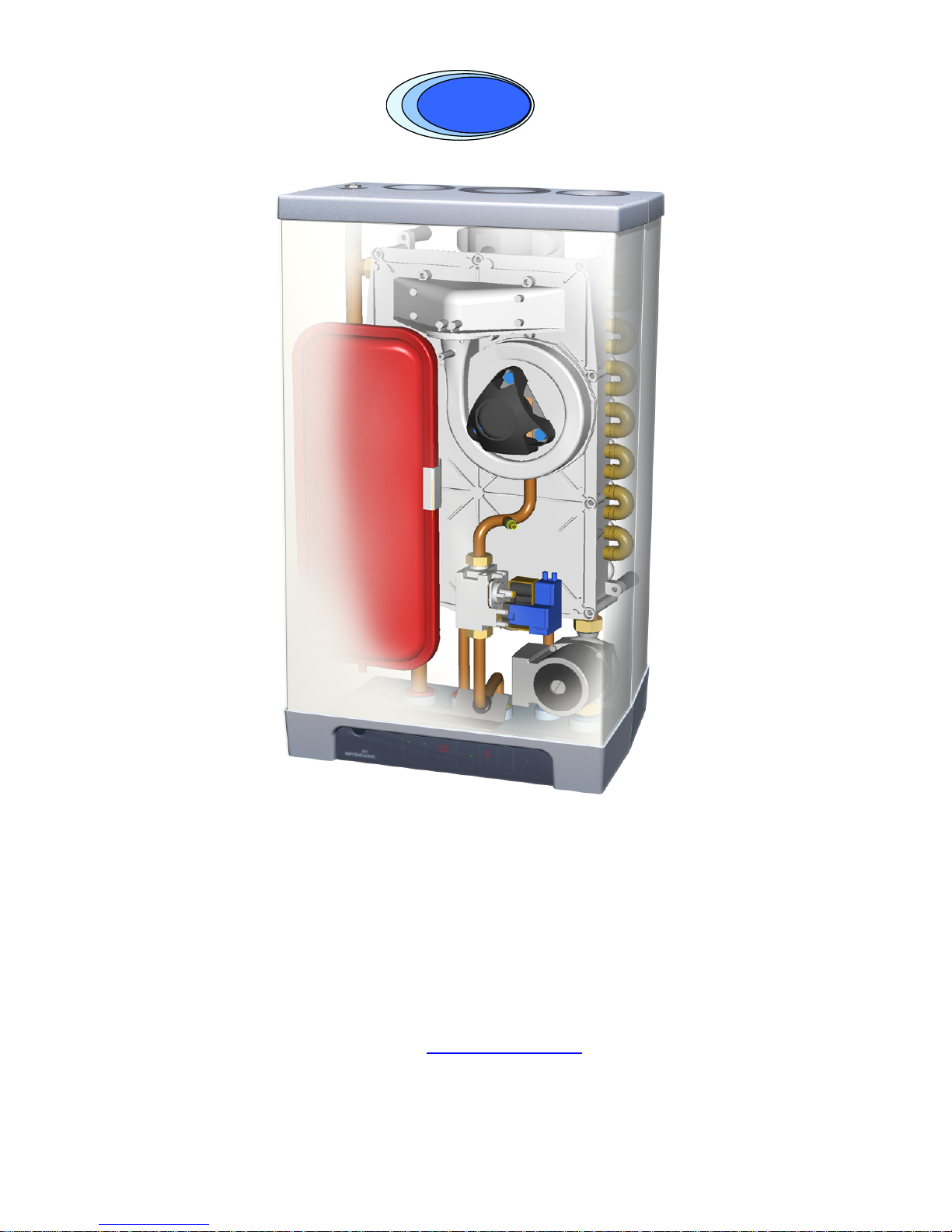
Atmos InterCombi
ATMO
S
ATMO
S
Installation Instructions
Atmos Heating Systems
West March
Daventry
Northants, NN11 4SA
Tel: 01327 871990
Fax: 01327 871905
e-mail:
sales@atmos.uk.com
internet: www.atmos.uk.com
Issue 1.4.05
Page 2

© 2005 Atmos Heating Systems
The information provided applies to the product in the standard model. Atmos Heating
Systems can therefore not be held liable for any damage resulting from the product
specifications that deviate from the standard model.
The information provided has been compiled with the utmost care. However, Atmos
Heating Systems cannot be held liable for any faults in the information nor for the
consequences thereof.
Atmos Heating Systems cannot be held liable for any damage resulting from the
activities carried out by third parties.
To be changed without prior notice
2
Page 3

TABLE OF CONTENTS
1. Safety Regulations 7
1.1 General.......................................................................................................................................................................7
1.2 CH system...................................................................................................................................................................7
1.3 Gas system.................................................................................................................................................................7
1.4 Electrical system.........................................................................................................................................................7
1.5 Domestic water system...............................................................................................................................................7
1.6 Flue discharge and air supply.....................................................................................................................................7
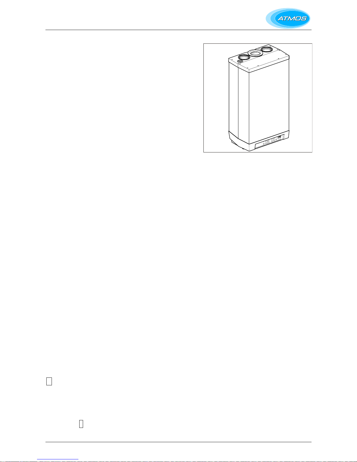
2. Description of the Appliance 8
2.1 General.......................................................................................................................................................................8
2.2 Operation....................................................................................................................................................................8
2.3 Operating conditions...................................................................................................................................................8
2.4 PC interface..............................................................................................................................................................10
2.5 Test programmes......................................................................................................................................................11
2.5.1 Frost protection................................................................................................................................................11
3. Main Components 12
3.1 Accessories...............................................................................................................................................................13
4. Installation 14
4.1 Overall dimensions....................................................................................................................................................14
4.2 Unpacking the appliance............................................................................................................................... ............15
4.3 Additional dimensions...............................................................................................................................................15
4.4 Boiler location............................................................................................................................................................16
4.4.1 Installation in a kitchen cupboard.....................................................................................................................16
4.4.2 Installation in an airing cupboard......................................................................................................................16
4.4.3 Remove front panel..........................................................................................................................................16
4.5 Mounting...................................................................................................................................................................17
4.5.1 Fitting the mounting strip..................................................................................................................................17
4.5.2 Fitting the mounting strip and the mounting bracket.........................................................................................17
4.5.3 Fitting the top connecting frame.......................................................................................................................17
4.5.4 Installation connections....................................................................................................................................17
4.6 Mount the appliance..................................................................................................................................................18
4.7 Fit the pipework cover...............................................................................................................................................18
5. Connections 19
5.1 Connect the CH system............................................................................................................................................19
5.1.1 Expansion vessel.............................................................................................................................................19
5.1.2 Thermostatic radiator valves............................................................................................................................19
5.1.3 System bypass.................................................................................................................................................19
5.1.4 Underfloor heating............................................................................................................................................20
5.2 Hot water system......................................................................................................................................................21
5.2.1 Appliance with pre-heating by solar system.....................................................................................................21
5.3 Connecting the gas supply........................................................................................................................................22
5.4 Electrical connection.................................................................................................................................................22
5.4.1 Electrical connections.......................................................................................................................................22
5.4.2 Room thermostat on/off....................................................................................................................................23
5.4.3 Outside temperature sensor.............................................................................................................................23
5.5 Flue discharge and air supply...................................................................................................................................24
5.5.1 Twin-pipe connection.......................................................................................................................................24
5.5.2 Concentric connection......................................................................................................................................24
5.5.3 Pipe, materials and insulation..........................................................................................................................24
5.5.4 Flue terminal clearances..................................................................................................................................25
5.5.5 Flue system......................................................................................................................................................25
5.6 Pipe lengths..............................................................................................................................................................26
5.6.1 Equivalent lengths............................................................................................................................................26
5.6.2 Example of 80mm twin pipe calculation...........................................................................................................26
5.6.3 Example of 80/125mm concentric pipe calculation..........................................................................................26
3
Page 4

5.6.4 Outlet arrangements.........................................................................................................................................27
5.6.5 Flue discharge pipe and air supply pipe...........................................................................................................27
5.7 Outside wall outlet for twin pipe terminal - horizontal................................................................................................28
5.8 Outside wall and roof outlet concentric terminal horizontal.......................................................................................30
5.9 Roof outlet combination and twin pipe terminal - vertical..........................................................................................31
5.10 Roof outlet prefabricated chimney............................................................................................................................. 34
5.11 Roof outlet and air supply from the outside wall........................................................................................................35
5.12 Air supply from the outside wall and a roof outlet with common discharge system...................................................36
5.13 Roof outlet CLV system............................................................................................................................................37
6. Commissioning 38
6.1 Fill and de-aerate the appliance and the system.......................................................................................................38
6.1.1 CH system........................................................................................................................................................38
6.1.2 Hot water supply...............................................................................................................................................38
6.1.3 Gas supply.......................................................................................................................................................38
6.2 Commissioning of the appliance...............................................................................................................................39
6.3 System Shutdown.....................................................................................................................................................40
6.3.1 Frost protection................................................................................................................................................40
7. Setting and Adjustment 41
7.1 Directly via operating panel.......................................................................................................................................41
7.2 Settings through the service code.............................................................................................................................41
7.3 Parameters................................................................................................................................................................42
7.4 Setting maximum CH power......................................................................................................................................43
7.5 Setting pump position................................................................................................................................................43
7.6 Weather-dependent control.......................................................................................................................................44
7.7 Conversion to other gas type....................................................................................................................................44
7.8 Gas-air control...........................................................................................................................................................44
7.9 Setting gas-air control...............................................................................................................................................45
8. Faults 47
8.1 Burner does not ignite...............................................................................................................................................48
8.2 Burner ignites with much noise.................................................................................................................................48
8.3 Burner resonates.......................................................................................................................................................49
8.4 No heating (CH)........................................................................................................................................................49
8.5 Reduced output.........................................................................................................................................................50
8.6 CH does not reach the correct temperature..............................................................................................................50
8.7 No hot water (HW)....................................................................................................................................................50
8.8 Hot water does not reach the correct temperature....................................................................................................51
9. SERVICING THE BOILER 52
10. Technical Specifications 53
10.1 Electrical diagram......................................................................................................................................................54
11. CE Declaration 55
4
Page 5

This manual
Using this manual you can safely install and maintain this appliance.
Carefully follow the instructions.
In case of doubt, contact Atmos Heating Systems.
Keep these instructions near the appliance.
Abbreviations and names used
Description To be referred
to as
High Efficiency HE
Atmos InterCombi wall-mounted gas heater Appliance
Appliance with piping for central heating CH system
Appliance with piping for domestic water HW system
Icons
The following symbols are used in this manual:-
CAUTION
Procedures that, when not carried out with due care,
may result in damage to the product or the
environment or in personal injury.
Service and technical support
For information about specific adjustments, installation, maintenance
and repair activities, please contact:
Atmos Heating Systems,
West March,
DAVENTRY,
Northants, NNII 4SA
www.atmos.uk.com
5
Page 6

Guarantee conditions
Considering the conditions mentioned below, Atmos guarantees towards
the recognised installer the soundness of the materials used, as well as
the good operation of its Central Heating products, if applied for their
intended use. When the occasion arises, we should be given the
opportunity to ascertain ourselves, if necessary on the spot, of the validity
of the guarantee claim.
The guarantee includes:
1. The guarantee is limited to the free redelivery of the parts showing material
or manufacturing faults that are not the result of normal wear and the like
during the guarantee period, entirely at our discretion. These parts should be
returned to us prepaid mentioning the defect and they will be our property
after replacement.
2. The guarantee period for parts is 2 years as from the date of installation.
However, the following parts have been excluded from guarantee: ignition
probe, ionisation pin, glass fuse, thermocouple and de-aerator.
3. The period of guarantee for the heat exchanger of the appliance is 5 years,
provided that if corrosion leaks occur that can, at our discretion, not be
remedied on the spot, we only deliver this part of the boiler for a fee of old for
new, calculated from the installation date at the time of replacement.
4. A copy of the completed Benchmark Boiler Commission Certificate must be
returned as proof of correct commissioning.
5. The guarantee shall no longer be valid when it is established that the
defects, damage or excessive wear are due to improper use or injudicious
treatment or to unskilful repair, adjustment, installation or maintenance by
non-approved installers.
6. The guarantee is no longer valid when the defect is the result of deposition of
scale (harmful to the appliance and the system). Surface damage and
transport damage are outside the scope of the guarantee. The right to
guarantee lapses if the boiler has not had a yearly service by an approved
service agent. The instructions of installation and use that we supply for the
respective appliances must be fully observed.
7. The guarantee is only valid if the return slip of the certificate of guarantee
has been returned to us within 8 days after the installation, signed by the
buyer. By signing the guarantee card, the buyer declares that he agrees with
the good state of the delivery.
8. If the installer's company was terminated before expiration of the guarantee
period, the user can make an appeal to our guarantee obligations towards
the installer.
Environment
When the appliance needs replacement, your installer may
arrange for disposal. Should this not be possible, then
make enquiries with your local council about the
possibilities for re-use or environmental-friendly processing
of the materials used, or contact a scrap dealer about
disposal.
Various plastics and metals have been used in producing
the appliance. Also, the appliance contains electronic
components that are electronic waste.
Intended use
The appliance as described in this documentation is intended for heating
rooms with a central heating system and/or for supplying hot water. Any
other use is outside the scope of intended use for this appliance. Any
liability for damage resulting from improper use shall not be accepted.
6
Page 7

1. SAFETY REGULATIONS
The appliance must be installed in accordance with the Gas Safety
(Installation and Use) Regulations; October 1994. Failure to install appliances
correctly could lead to prosecution.
Atmos Heating Systems does not accept any liability for damage or injury
caused by not (strictly) observing the current safety regulations and
instructions, nor by negligence while installing the Atmos InterCombi wallmounted gas heater and any accompanying accessories.
The manufacturer’s instructions must NOT be taken as overriding statutory
requirements.
The regulations are mentioned separately for the different disciplines.
1.1 General
The entire system should comply with the valid (safety) regulations, as
mentioned in:-
• This installation manual.
• Gas Safety (Installation and Use) Regulations
• The appropriate Building Regulations.
• Health and Safety Document No 635 (Electricity at Work Regulations)
• The Water Fittings Regulations or local Water byelaws.
1.2 CH system
The entire system should comply with the valid (safety) regulations, as
mentioned in:-
•
BS 5449 Central Heating for Domestic Premises.
1.3 Gas system
The entire system should comply with the valid (safety) regulations, as
mentioned in:-
•
BS 6798 Specification for installation of gas fired hot water boilers of rated input
not exceeding 60 kW
.
•
BS 6891 Installation of low pressure gas pipework installations up to 28mm
(R1).
• I.S.813 Installation of Gas Appliances (for installations in Ireland).
• British Gas Guidance Notes for the Installation of Domestic Gas Boilers.
1.4 Electrical system
The entire system should comply with the valid (safety) regulations, as
mentioned in:-
• BS 7671 The IEE Wiring Regulations.
1.5 Domestic water system
The entire system should comply with the valid (safety) regulations, as
mentioned in:-
•
BS 5546 Installation of gas hot water supplies for domestic purposes.
1.6 Flue discharge and air supply
The flue discharge and the air supply system should comply with:-
•
BS 5440 Flues and Ventilation for gas appliances of rated input not exceeding
60 kW. (Part 1 Flues and Part 2 Ventilation).
7
Page 8
2. DESCRIPTION OF THE APPLIANCE
2.1 General
The Atmos InterCombi wall-mounted gas boiler is a balanced flue
appliance, designed for delivering heat to the water of a CH system and
the domestic hot water.
The air supply and flue discharge can be connected to the appliance by
means of two separate pipes. A concentric connection can be delivered
upon request. The appliance has been inspected together with the
Atmos combination lead-through, but the appliance can also be
connected to combination terminals that comply with the universal test
requirements for combination terminals and that have a gas certification.
The appliance can also be fitted to an optional mounting bracket, a
frame with top connection and various connecting sets. These are
supplied separately.
The Atmos InterCombi wall-mounted gas boiler has the CE quality mark
and the Gas certification labels HE (Sedbuck A), SV , NZ (Solar
compatible) and CW Class 5 (Hot water performance rating 1 to 6,
where 6 is the highest) and IP44.
It is possible to use the appliance for hot water or for heating only. The
system that is not used does not need to be connected.
The appliance as delivered is suitable for natural gas (G20). A
conversion kit for propane (G31) can supplied upon request.
2.2 Operation
The Atmos InterCombi wall-mounted gas heater is a modulating high
efficiency boiler. This implies that the power is adjusted to the heat
demand.
In the aluminium heat exchanger two separate copper circuits have been
integrated.
Because of the separated circuits for central heating and hot water, the
heating and the hot water supply can operate independently of each
other. The hot water supply has priority over the heating. They cannot
work simultaneously.
The appliance has been provided with an electronic burner controller
that controls the fan with each heat demand from the heating system or
the hot water supply, opens the gas valve and ignites the burner and
continuously monitors the flame and controls it dependent on the power
required.
2.3 Operating conditions
A code indicates the operating condition of the appliance on the service
display of the operating panel.
- Off
The appliance is not operating, but there is electrical power. There is no
response to any demand for hot domestic hot water or CH water. The
frost protection is active though. This means that the pump starts
running and the heat exchanger is heated when the temperature of the
water present here drops below 4 °C. When the frost protection is
activated, code
7 appears (heating of the heat exchanger).
8
Page 9

Waiting position
The LED of the on/off key and if necessary one of the LED’s of the
domestic hot water comfort function are on. The appliance is ready for
responding to the demand for CH or domestic hot water.
0 Pump overrun
After the operation of the CH, the pump has an overrun. This overrun time
is set to the value according to table 4 at the factory. This setting can be
changed. Also, the controller will automatically run the pump for 10
seconds, once every 24 hours, to prevent it from getting stuck. This
activation of the pump takes place at the time of the last heat demand. In
order to change this time, set the room thermostat higher for a while at the
desired time.
1 Required temperature reached
The burner controller can temporarily block the heat demand and stop the
burner. This blocking takes place because the required temperature has
been reached. When the temperature has dropped sufficiently, the
blocking is cancelled.
2 Self-test
The burner controller regularly checks the connected sensors. During the
check, the controller does not carry out any other tasks.
3 Ventilate
At starting the appliance the fan is first brought to the starting speed.
When reaching the starting speed, the burner is ignited. Code
3 is also
visible when after stopping the burner post-purge takes place.
4 Ignite
When the fan has reached the ignition speed, the burner is ignited by
means of electric spark ignition. During ignition the code
4 appears. If
the burner is not ignited, another ignition attempt is made after about
5 seconds. If the burner has still not fired after the fourth ignition attempt,
the controller indicates a fault. See § 8.1.
5 CH operation
An on/off thermostat can be connected to the controller, if necessary in
combination with an outside sensor. See Electrical diagram. When heat is
demanded by a thermostat signal, the fan runs (code
3 ) and the burner is
ignited (code 4 ), followed by the CH operating condition (code 5 ).
During CH operation, the fan speed and hence the power of the appliance
is adjusted. This is done in such a way, that the temperature of the CH
water is controlled towards the set CH supply temperature. In the case of
an on/off thermostat, the CH supply temperature is set at the operating
panel. In the case of an outside sensor, the CH supply temperature is
determined by the weather dependent control programmed in the burner
controller.
9
Page 10

During CH operation, the demanded CH supply temperature is displayed
on the operating panel. The resistance R in the Electrical diagram can
be removed when the room thermostat does not need any anticipation
current.
During CH operation, the CH supply temperature can be set between
30ºC and 90ºC and the set CH supply temperature is displayed on the
operating panel. During CH operation, the actual CH supply temperature
can be read by pressing the service key.
6 Domestic hot water operation
The hot water supply has priority over the heating. When the flow switch
detects a domestic hot water demand of more than 2 l/min, the CH
demand is interrupted. After starting the fan (code
3 ) and ignition of the
burner(code 4 ), the controller goes to domestic hot water operation
(code 6 ).
During domestic hot water operation, the fan speed and hence the
power of the appliance is controlled by the controller on the basis of the
set domestic hot water temperatures. The domestic hot water
temperature can be set between 50ºC and 60ºC. The set temperature is
displayed on the operating panel.
During domestic hot water operation, the actual domestic hot water
supply temperature can be read by pressing the service key.
7 Heating the appliance
For a quick supply of domestic hot water, a comfort function has been
provided in the controller. This function keeps the heat exchanger at the
correct temperature. This comfort function has the following settings:-
• Off: (Both LEDs off.) The heat exchanger is not kept warm,
delaying the supply of domestic hot water. When there is no
demand for domestic hot water, the comfort function can be
switched off.
• On: The comfort function of the appliance is continuously
activated. The appliance always supplies domestic hot water
immediately.
• Eco: The comfort function is self-learning. The appliance is
inactivated during the night or after a long absence. The appliance
adjusts to the user pattern of the domestic hot water requirements.
The eco mode is the most efficient hot water method.
2.4 PC interface
The controller has an interface for a PC. With a special cable and
accompanying software, a PC can be connected. This provision makes it
possible to follow the behaviour of the controller, the appliance and the
heating system during a long period.
10
Page 11
2.5 Test programmes
In the burner controller, there is provision for putting the appliance into a
test status.
By activating a test programme, the appliance will become active with a
fixed fan speed without intervention of the control functions. The safety
functions remain active though.
Simultaneously press + and – to switch off the test programme.
Test programmes
Description of programme Key combinations Display
reading
Burner on with minimum CH
power
"service" and "-" “L”
Burner on with maximum
CH power
"service" and “+” (1x) “h”
Burner on with maximum
HW power
"service" and "+" (2x) "H"
Switch off test programme "+" and "-" Current
operating
condition
2.5.1 Frost protecti on
The boiler has provision for protecting its heat exchanger as described
below.
NOTE! However to avoid the condensate freezing, the boiler must be
installed in a FROST-FREE room.
• In order to avoid freezing of the appliance (heat
exchanger), it has an appliance frost protection.
When the temperature of the heat exchanger drops
to 5ºC, the burner will be activated and the pump
will start running until the temperature of the heat
exchanger reaches10ºC.
Code
7 is given when the appliance frost
protection intervenes (heating heat exchanger).
• When the system (or a part thereof) can freeze, a
frost thermostat should be installed in the area to
be protected. Connect this according to the wiring
diagram. See § 10.1.
Remark
When the appliance is out of action (
- on the service display), the
appliance frost protection is still active. However, there will be no
response to heat demand from an (external) frost thermostat.
11
Page 12
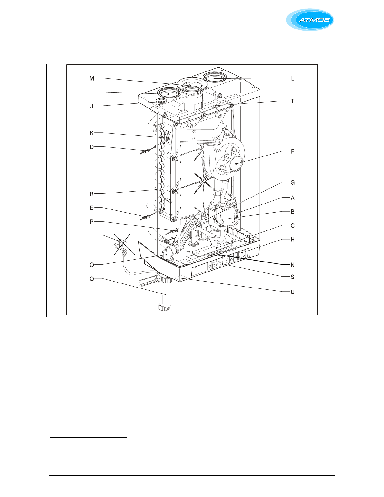
3. MAIN COMPONENTS
A CH pump L Air supply
B Gas valve M Flue discharge
C Burner controller with operating panel N Connecting block / terminal list X
D Supply sensor S1 O Condensate discharge
E Return sensor S2 P Hot water sensor S3
F Fan Q Siphon
G Flow switch R Heat exchanger
H Pressure gauge S Operating panel and display
I 1m connecting cable 230 V ~
( Note: Plug must be removed)
T Ionisation/ignition probe
J Manual air vent U Position type plate
K Sight glass and mirror
Additional Components supplied :T-piece & ½" Pressure relief safety valve, 3 bar (supplied in boiler box)
Valve set (supplied separately with boiler)
12
Page 13
3.1 Accessories
Description
Pipe mounting bracket
• Connection supply and return 22 mm diameter
• Connection cold and hot water 15 mm diameter
• Connection gas ½" female thread
• Mounting strip boiler
• Bag with fixings
Mounting frame for top pipe connection
Pipework cover
Outside sensor
Conversion set to Propane (LPG or G31)
Interface cable
13
Page 14
4. INSTALLATION
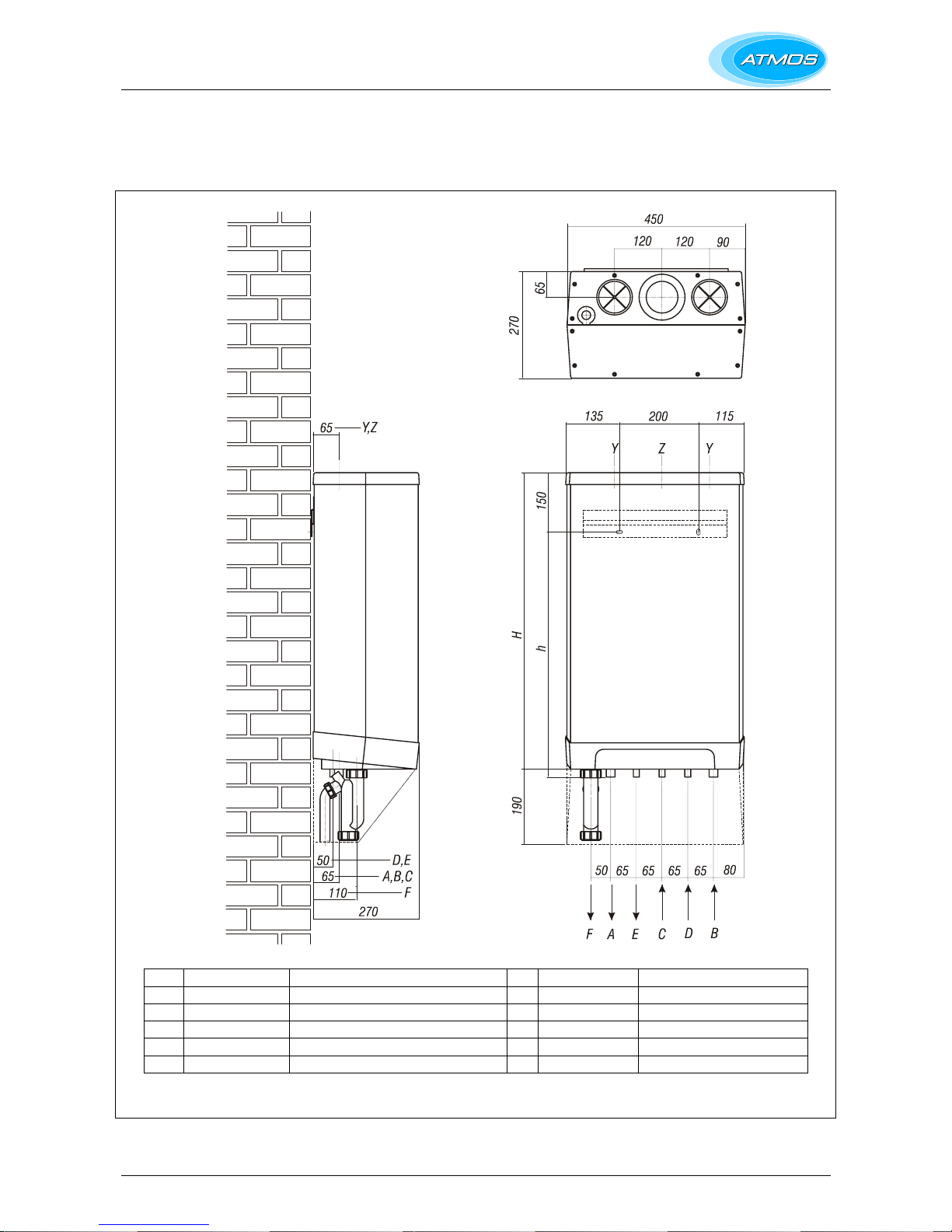
4.1 Overall dimensions
A= CH flow 22 mm diameter h= 710mm InterCombi HE 32
B= CH return 22 mm diameter I
C= Gas 15 mm diameter H= 810mm InterCombi HE 32
D= Cold water 15 mm diameter
E= Domestic hot water 15 mm diameter Z= Flue gas outlet 80 mm diameter
F= Condensate 32 mm dia (after siphon 25 mm dia flexible) Y= Air supply inlet 80 mm diameter
14
Page 15
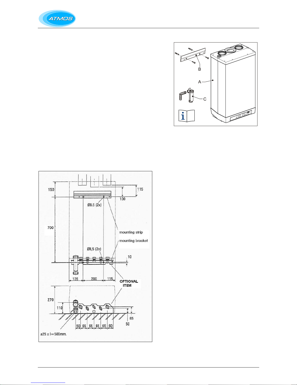
4.2 Unpacking the appliance
1. Unpack the appliance.
2. Check the content of the packaging. This consists of:-
• Appliance (A)
• Mounting strip (B)
• Siphon (C)
• T-piece & ½" Pressure relief safety valve, 3 bar
• Installation instructions
• Guarantee card
• Valve set (supplied separately with boiler)
3. Check the appliance for any damage: report damage to the Supplier
immediately.
4.3 Additional dimensions
The diagram shown below gives additional dimensions primarily for the
mounting arrangement using the OPTIONAL mounting bracket.
15
Page 16

4.4 Boiler location
The appliance can be fitted to a mounting frame. The assembly or just
the appliance should be mounted to a wall with sufficient bearing
strength.
In case of light wall constructions, resonance sounds may occur. There
must be an earthed electrical supply within a distance of 1 m from the
appliance. If the appliance is installed as an open appliance, the
installation room should have been provided with the required openings
for the boiler air supply.
In order to avoid freezing of the condensate discharge, the appliance
should be installed in a frost-free room.
Keep 5 cm free space above the appliance in order to be able to remove
the front panel from the casing.
4.4.1 Installation in a kitch en cupboard
Make sure there is sufficient ventilation above and below the appliance.
When the appliance is placed in a small cupboard, ventilation openings
of at least 50 cm
2
must be made.
4.4.2 Installation in an airing cup board
Compartment ventilation is not required for a standard airing cupboard
(eg 0.6 x 0.6 x 2.3m high).
4.4.3 Remove front panel
Remove the pipework cover and the front panel for carrying out work on
the appliance as follows:-
1. Remove the pipework cover (A), if used, forwards.
2. Unscrew both screws (B) at the bottom of the appliance.
3. Lift the front panel (C) and remove it forwards.
16
Page 17
4.5 Mounting
A
B
B
C
Depending on the mounting option ordered, the following mounting
methods are available:-
Mounting strip (A) alone,
OR mounting strip (A) and optional pipe mounting bracket (B),
OR top connecting frame (C) and pipe mounting bracket (B), which are
both optional items. This arrangement allows for vertical pipes from
above at the rear.
Note that when the pipe mounting bracket is used, the pipes can be
connected before installing the appliance.
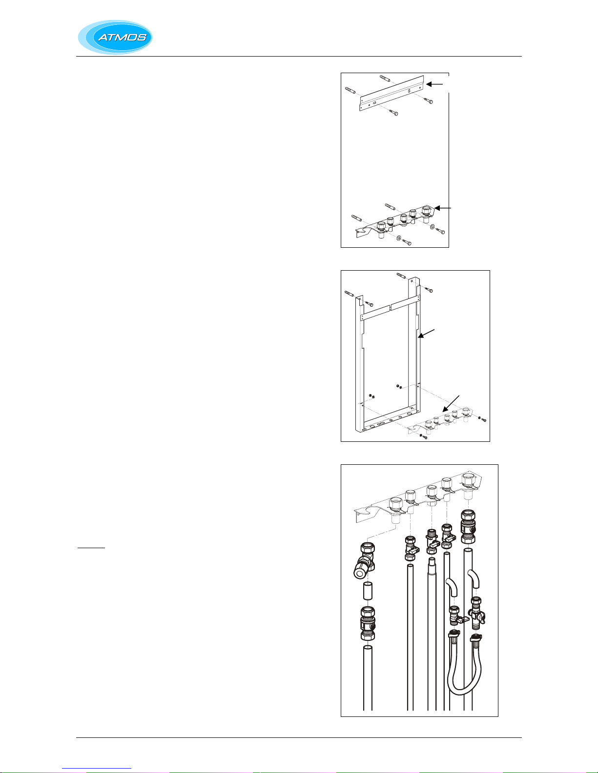
4.5.1 Fitting the mounting strip
1. Fasten the mounting strip horizontally to the wall, using the
fastening materials supplied.
2. Mount the appliance.
3. Mount the parts of the various connecting sets.
Note that the 3 bar pressure relief valve must be installed on the
boiler side of the CH flow valve (see diagram).
4.5.2 Fitting the mounting strip and the mounting bracket
1. Fasten the mounting strip and the pipe mounting bracket
horizontally to the wall according to the drilling pattern, using the
fastening materials supplied.
2. Mount the parts of the various connecting sets.
Note that the 3 bar pressure relief valve must be installed on the
boiler side of the CH flow valve (see diagram).
4.5.3 Fitting the top connecting frame
1. Fasten the frame vertically to the wall, using the fastening materials
supplied.
2. Fasten the pipe mounting bracket to the frame using the fastening
materials supplied.
3. Mount the parts of the various connecting sets.
Note that the 3 bar pressure relief valve must be installed on the
boiler side of the CH flow valve (see diagram).
4. Slide the connecting pipes into the frame.
Caution
The appliance is wider than the frame.
4.5.4 Installation co nnections
1. Make the various connections to the valves (see diagram).
2. Install a filling loop (not supplied) between the cold water inlet pipe
and the CH return connection.
3. Install an overflow pipe from the pressure relief valve, using 2 x 90
0
bend to step the pipe to the rear so that it will enter the condensate
discharge pipe.
17
Page 18

4.6 Mount the appliance
1. Check whether the clamping rings are straight in the couplings.
2. Place the appliance: slide it top-down over the mounting strip. Make
sure that the pipes simultaneously slide into the clamp fittings.
3. The flexible tube from the condensate siphon should be inserted
into an open waste pipe of not less than 32 mm diameter. If
connected to a soil pipe or waste system, the waste pipe must
include a trap (similar to arrangement for washing machine).
The 15 mm safety discharge copper pipe from the pressure relief
safety valve may also be taken into this pipe (as shown in the
diagram, §5.1) or, alternatively, taken to a safe discharge position
on the outside wall of the building.
4. Tighten the clamping fittings to the mounting bracket.
5. Mount the air supply and the flue discharge.
6. Close the air supply opening that is not used with the plug supplied.
4.7 Fit the pipework cover
1. Insert the four hooks of the pipework cover in the slots of the
appliance.
2. Slide the cover backwards, sliding the hooks into the slots and
locking the cover.
18
Page 19

5. CONNECTIONS
5.1 Connect the CH system
1. Flush the CH system thoroughly.
2. Mount the supply and return pipes to the mounting bracket.
All pipes must be mounted tension-free in order to avoid ticking of
the pipes.
Existing connections must not be twisted in order to avoid leaks at
the connections with the external pipes.
The CH system should have been provided with.
• A filling loop in the return pipe directly below the appliance.
• A drain tap at the lowest point of the system.
• A pressure relief valve of 3 bar in the supply pipe at a
maximum distance of 500 mm from the appliance.
Between the appliance and the pressure relief valve there must
not be a shut-off valve or a constriction
• An expansion tank in the return pipe (see also 5.1.1).
• A non-return valve when pipes are running upward at a short
distance from the appliance. This prevents a gravity effect
during domestic hot water operation of the appliance.
5.1.1 Expansion vessel
The appliance is fitted with a 6 litre expansion vessel which is adequate
for a system with a water volume not exceeding 100 litres, typically 8
radiators. For larger volume systems, an additional expansion vessel
must be fitted. Contact Atmos for advice in these cases.
5.1.2 Thermo static radiator valves
Building regulations require a room thermostat to be fitted on all
installations. Do not fit a thermostatic valve on the radiators in the room
where the thermostat is situated, otherwise the controls will not function
correctly.
5.1.3 System bypass
A bypass is not generally required. If, however, the heating system uses
2 port valves which close fully (‘S’ plan), a bypass should be fitted before
the valves.
19
Page 20

5.1.4 Underfloor heating
For a good operation of the domestic hot water supply, there must be no
undesired circulation through the appliance caused by a second pump of
the CH circuit.
Connect underfloor heating with an electric shut-off valve (two-way
valve) to prevent circulation through the appliance when there is no
demand for central heating.
A. Boiler
B. Pump
C. Thermostatic control valve
D. Spring-operated non-return valve
E. Electrical shut-off valve 230 V ~
F. Radiators
G. Room/clock thermostat
H. Maximum thermostat
20
Page 21

L/min
Bar
5.2 Hot water system
1. Flush the system thoroughly.
2. Mount the cold and hot water pipe to the mounting bracket.
Remarks
• To comply with the Water Regulations, the max. length of an
uninsulated hot water pipe with a diameter of 15 mm is 12 m; and
the max. length of an uninsulated hot water pipe with a diameter of
12 mm is 20 m.
Note that it s preferable to insulate the hot water pipes.
• When the appliance is used for hot water supply only, the heating
function can be switched off with the service code on the operating
panel. The CH system does not need to be connected or filled.
• If the appliance is shutdown during the winter, the domestic hot
water should be drained to prevent freezing. For this, the cold
water connection at the bottom of the appliance must be
disconnected.
A (Not applicable)
B. InterCombi HE32
X. Water pipe pressure in bar
Y. Water flow rate in l/minute ± 10%
5.2.1 Appliance with pre-heating by solar system
A connecting set for appliances with the NZ label "Suitable for preheating by solar system" is available upon order.
A. Thermostatic mixing valve 40° - 90° (set to 60°)
B. Hot water
C. Mixed water out
D. T max 90°C
E. Cold water
F. Cold water in
G. Inlet combination
H. Flow switch
Remark
• In combination with the solar energy system, a thermostatic mixing
valve set to 60°C must always be placed downstream of the
appliance.
21
Page 22

5.3 Connecting the gas supply
1. Install a gas filter in the connection of the appliance when the gas
can be polluted.
2. Connect the appliance gas valve to the gas pipe.
3. Check the boiler's data plate to ensure that the appliance has been
set for the correct gas supply. The boiler is supplied for Natural Gas
(G20). A propane (G31) gas conversion set is available and an
appropriate sticker is included (see §7.7).
4. The meter governor should deliver a dynamic pressure of 20mbar
for natural gas or 37mbar for propane.
5. To prevent the ingress of foreign matter and possible damage to the
gas-regulating block, the gas supply pipe must be checked for
contaminants prior to connection to the boiler.
6. On final connection of the gas supply to the boiler, the complete gas
installation, including the meter, must be tested for gas soundness
and purged as described in BS6891.
5.4 Electrical connection
CAUTION
The appliance requires a 230 V ac 50 Hz mains supply, and
must be earthed and connected via a double pole isolating
switch fitted with a 3 amp fuse. The switch must be readily
accessible, within 1m of the appliance, and provide
complete electrical
isolation for the boiler and control
system.
The appliance is supplied factory wired complete with 1 m
of mains cable. (Note – the plug must be removed from the
cable). All electrical connections to the mains supply must
be made in full accordance with the current I.E.E.
regulations (BS 7671).
Isolate the supply by opening the double pole switch
when carrying out maintenance activities.
1. Remove the pipework cover forwards.
2. Unscrew the screws (A) in order to gain access to the space of the
burner controller (B).
3. The cover plate hinges open downwards. Here hold the display
window.
4. Consult § 5.4 and § 10.1 for making connections.
5. After having made the required connections, connect the appliance
to a switched supply, as given above.
5.4.1 Electrical connections
Temperature control Connector X4 Remarks
Room thermostat 6 - 7 Outside temperature sensor 8 - 9 External economy switch 4 - 5 Remove link
Frost thermostat 6 - 7 Parallel through
room thermostat
Power 24 V dc (3VA) 6= +, 9= - Power supply
available for clock
thermostat, etc
22
Page 23

5.4.2 Room thermo stat on/off
1. Connect the room thermostat. See § 5.4.1.
2.
The terminal block for the connection for a volt free room thermostat, or
time clock, is X4 on the control panel. The terminals are wired to the
input circuit of the control unit, which has its own 24V dc ‘wetting
voltage’
.
3.
If using a room thermostat with heat accelerator, this must be set at
0·1A.
4.
The maximum permissible resistance of the room thermostat circuit
and cable is 15 Ohms.
5.
Where a 'wireless' room thermostat is employed, consult the
manufacturer’s instructions for installation.
Note -
Under no circumstances must any electrical power be input to
the room thermostat terminals. It is a volt-free switch.
Note - Care must also be taken to avoid induced voltages caused by
the running of the thermostat cables along side mains voltage cables.
5.4.3 Outside temperature sensor
The appliance has a connection for an outside temperature sensor. The
outside temperature sensor can be applied in combination with an on/off
room thermostat.
Connect the outside temperature sensor. See § 5.4.1.
See Weather-dependent control § 7.6 for the setting of the CH
temperature line.
23
Page 24

5.5 Flue discharge and air supply
Two different flue systems are available from Atmos for use with this
appliance:-
• 80mm twin pipe system which enables separate air intake and flue
pipes to be fitted to the appliance.
• 80/125mm concentric system.
Maximum lengths are specified in § 5.6 and must not be exceeded.
Note - A special concentric through the wall flue kit (60/100mm) is
available from Atmos.
5.5.1 Twin-pipe connection
1. When using the right-hand air supply, the sealing cap and the
insulating foam lying beneath must be moved to the left-hand air
supply.
2. Locate the pipes for the air supply and flue discharge in the supply
and discharge stubs. The in-built silicone sealing ring provides an
airtight connection.
5.5.2 Concentric connection
Using the concentric adapter set, the standard two-pipe connection can
be changed into a concentric connection.
1. Seal the open air supply connections in the appliance with the
sealing cap delivered with the set (foam plug).
2. Remove the sealing ring around the flue discharge in the appliance.
3. Fit the sealing ring ø 116 x 110 mm.
4. Fit the adapter on the flue discharge.
5.5.3 Pipe, materi als and insulation
Pipe Diameter Material
Air supply ø 80 mm According to the local regulations of
fire department and/or power
company.
Single wall aluminium, galvanized
steel plate, stainless steel or plastic.
If necessary insulated with 10 mm
vapour-tight insulating material or
plastic.
Flue discharge ø 80 mm Aluminium single wall 1.5mm thick.
Insulation - 10 mm vapour-tight insulating
material when there is a chance of
condensation on the outside,
caused by a low wall temperature
and a high room temperature with a
high humidity.
24
Page 25

5.5.4 Flue terminal clearances
The flue terminal must be sited with minimum
clearance distances as shown in the diagram.
A terminal
g
uard must be fitted if the terminal
is sited less than 2m above ground level.
Where the flue terminates within 1m of
a
plastic or painted gutter or within 500mm o
f
painted eaves, then protection should be
provided in the form of an aluminium shield a
t
least 1m in length, fitted to the underside o
f
the gutter or painted surface.
Please Note!
Due to the low flue gas temperature, 'pluming
'
will occur at the flue terminal. Care should b
e
taken to ensure that the discharge plume wil
l
not cause annoyance to the customer o
r
neighbours. It is generally recommended tha
t
flues should discharge vertically at roof level.
In this position, pluming is not normall
y a
problem.
5.5.5 Flue system
The flue system must be installed in accordance with BS5440:1.
Horizontal flue pipe runs must always be installed with a minimum slope of
50 mm/metre towards the boiler. This will prevent condensation from
gathering in the flue pipe, and will also reduce the chance of icicles
forming over horizontal pipe ends in the Winter.
25
Page 26

5.6 Pipe lengths
As the resistance of the flue discharge and air supply pipes increases,
the capacity of the appliance will decrease. The maximum allowed
power decrease is 5%.
The resistance of the air supply and the flue discharge depends on the
length, the diameter and all components of the pipe system. The total
allowed pipe lengths of the air supply and the flue discharge are given
below:-
Note for twin pipes
The total pipe length is:The length of all straight pipe lengths and the
lengths of the equivalent pipe lengths of bends.
The maximum length of the air supply and flue
discharge 80mm pipes added together is 60 m.
Note for concentric pipes
The total pipe length is:The length of all straight pipe lengths and the
lengths of the equivalent pipe lengths of bends.
The maximum length of the 80/125mm concentric
pipe is 24 m for horizontal pipe and 27 m for vertical
pipe.
5.6.1 Equivalent len gths
Bend at 90° R/D=1 2 m
Bend at 45° R/D=1 1 m
Elbow at 90° R/D=0.5 4 m
Elbow at 45° R/D=0.5 2 m
Note – The type supplied by Atmos are Elbows.
For smaller twin pipe diameters, the maximum pipe length is reduced as
follows:-
70mm dia: 0.59 x max. pipe length for 80mm dia.
60mm dia: 0.32 x max. pipe length for 80mm dia.
50mm dia: 0.15 x max. pipe length for 80mm dia.
Note that Atmos only supply 80mm twin pipes
5.6.2 Example of 80mm twin pipe cal culation
See diagram.
Pipe Pipe lengths Total pipe lengths
Flue discharge L1 + L2 + L3 + 2 x 2 m 13 m
Air supply L4 + L5 + L6 + 2 x 2 m 12 m
Total length 25m
5.6.3 Example of 80/125mm concentric pipe calculation
With 3 elbows at 90°, the max straight length of concentric pipe that can
be used is 24m – 3x4m = 12m.
26
Page 27

5.6.4 Outlet arrangements
Appliance
category
Materials Supplier
Terminal Atmos C13
Other parts
Terminal
Terminal of Prefabricated
chimney
C33
Other parts
All materials C43
At the CLV system
Inlet grid C53
Other parts and discharge
cover
C63 All materials and terminal
Inlet grid
Main duct
C83
Other parts
5.6.5 Flue discharg e pipe and air supply pipe
The mounting below applies to all outlets:-
1. Slide the flue discharge pipe into the discharge stub of the appliance.
2. Slide the flue discharge pipes into each other.
From the appliance all pipes must be slid into the previous one.
3. Mount a non-vertical flue discharge pipe in a slope to the appliance
(min. 50 mm/m).
4. Mount the folded seams directed upwards in a horizontal part.
5. Tape up non-gastight connections with heat and moisture-resistant
aluminium tape.
The mounting below applies to all air supply pipes:-
1. Slide the air supply pipe into the supply stub of the appliance.
2. Tape up non-airtight connections with moisture-resistant tape.
3. Fit insulation, if necessary.
27
Page 28

5.7 Outside wall outlet for twin pipe terminal -
horizontal
Appliance category: C13
CAUTION
Pipes for connecting the air supply and the flue discharge
between the appliance and the terminal must have a
diameter of 80 mm.
A. Atmos twin pipe terminal horizontal. To be extended for a balcony
outlet with one or two standard pipes (diameter 80 mm).
B. Outlet grid.
C. Wall cover plate (2x).
Maximum pipe length
See §5.6.
Flue discharge pipe and air supply pipe
For mounting, see § 5.6.5.
Mounting twin pipe terminal
1. Make two openings of diameter 90 mm at the place of the outlet.
2. Cut the pipes to the correct length.
3. Slide the supply and discharge pipes into the openings.
4. Cover the openings with wall cover plates.
5. Mount the outlet grids to the supply and discharge pipes.
6. Attach them to the pipes.
7. Ensure the pipes slope back to the appliance.
28
Page 29

Mounting a twin pipe terminal extension pipe(s) for balcony outlet
When the free outlet is hindered by an eave, balcony, gallery or anything
else, the air supply pipe and the flue discharge pipe must be extended to
at least the front side of the overhanging part.
When the air supply is not disturbed by obstacles, such as a console or
separating wall, and when the outlet is not at the edge of a building, the
air supply pipe does not need extension.
1. Extend the flue discharge pipe and, if necessary, also the air supply
pipe of the terminal with standard flue discharge and air supply
pipes to the correct length required.
2. Slide the flue discharge pipe and, if necessary, also the air supply
pipe into the discharge and supply pipes of the terminal.
3. Ensure the pipes slope back to the appliance.
4. Mount the outlet grids to both pipes.
29
Page 30

5.8 Outside wall and roof outlet concentric terminal
horizontal
Appliance category: C13
CAUTION
Pipes for connecting the air supply and the flue discharge
between the appliance and the terminal must have a
diameter of 80 mm.
A. Atmos concentric terminal horizontal.
For outside wall or roof outlet horizontal.
B. Atmos concentric pipe.
For extension of a balcony/gallery outlet.
Maximum pipe length
See §5.6.
Flue discharge and air supply pipes
For mounting, see § 5.6.5.
Mounting 80/125mm horizontal terminal
B
1. Make an opening of diameter 130 mm at the place of the outlet.
2. Shorten the terminal to the length required.
3. Mount the outlet grid and attach this to the inside pipe.
4. Slide the terminal into the opening and fit rosettes to cover the
opening.
5. Ensure the pipes slope back to the appliance.
30
Page 31

Mounting of combination extension pipe for balcony/gallery outlet
When the free outlet is hindered by an eave, balcony, gallery or anything
else, the combination terminal must be extended to at least the front side
of the overhanging part.
1. Mount the combination extension pipe to the combination terminal.
2. Shorten the combination terminal or the combination extension pipe
to the correct length required.
3. Mount the outlet grid and attach this to the inside pipe.
4. Mount the combination terminal and combination extension pipe in
a slope to the appliance.
5.9 Roof outlet combination and twin pipe terminal -
vertical.
Appliance category: C33
CAUTION
When the Atmos combination terminal - vertical cannot be
applied, the air supply and the flue discharge must be
separated.
Atmos combination terminal - vertical.
31
Page 32

Maximum pipe length
See §5.6.
Flue discharge pipe and air supply pipe
For mounting, see § 5.6.5.
Mounting of combination terminal - vertical
1. Mount a vertical terminal roof pile with lead flashing at the place of
the outlet on a pitched roof.
On a flat roof an adhesive plate for a pipe of diameter 126 mm must
be applied.
2. Dismount the manifold of the combination terminal (C).
3. Slide the combination terminal(C) from the outside to the inside.
With a pitched roof through the vertical terminal tile with shell.
With a flat roof through the adhesive plate.
4. Mount the manifold of the combination terminal (C) and lock it with
a sheet-metal screw or pop rivet.
32
Page 33

Mounting of twin pipe terminal - vertical
CAUTION
The outlets of the flue discharge and air supply should be
placed in the same pressure area.
The air supply from the pitched roof area and the flue
discharge by means of a constructional chimney is also
possible, but not the other way around.
1. Mount a double-walled flue terminal (diameter 80 mm) with Giveg
discharge cover on a pitched roof at the place of the outlet.
2. Mount a ventilating passage (diameter 80 mm) with cross-cut in the
corresponding roof passage tile for the air supply.
3. Mount for the flue discharge a double-walled flue terminal (diameter
80 mm) with Giveg discharge cover at the place of the outlet.
Mount with a flat roof or a constructional chimney and for the air
supply a ventilating passage (diameter 80 mm) with cross-cut in the
corresponding adhesive plate.
CAUTION
Two outlets must be at a distance of at least 200 mm from
each other.
33
Page 34

5.10 Roof outlet prefabricated chimney
Appliance category: C33
When there is little space in a shaft, a roof outlet through a prefabricated
chimney may be necessary.
The prefabricated chimney must comply with the minimum lengths
shown. The supplier must guarantee the proper operation of the
prefabricated chimney with respect to wind attack, ice formation, rain
ingress, etc.
In view of the different models and requirements, the prefabricated
chimneys must be adjusted to the local situation: a gas certificate is not
required.
CAUTION
The connection of the air supply and the flue discharge
between the appliance and the prefab chimney must be
made in pipes of diameter 80 mm.
Maximum pipe length
See §5.6.
Flue discharge and air supply pipes
For mounting, see § 5.6.5.
Mounting of prefabricated chimney
The outlet can be made at any place in the pitched or flat roof surface.
34
Page 35

5.11 Roof outlet and air supply from the outside wall
Appliance category: C53
CAUTION
The air supply (A) in the outside wall must be provided
with an Atmos inlet grid.
A. Flue discharge (B) through a prefabricated chimney or through a
double-walled roof passage diameter 80 mm with Giveg discharge
cover.
Maximum pipe length
See §5.6.
Flue discharge pipe and air supply pipe
For mounting, see § 5.6.5.
Mounting of air supply - horizontal
The air supply (A) can be made at any place in the outside wall.
1. Make an opening of diameter 90 mm at the place of the supply.
2. Shorten the air supply pipe to the correct length out of the wall.
3. Mount the Atmos inlet grid and attach this to the pipe.
4. Slide the air supply pipe into the opening and cover the opening
with a rosette, if necessary.
5. Mount the air supply at the place of the outside wall terminal in a
slope to the outside, to prevent rain from entering.
Mounting flue terminal - vertical
1. Mount a roof tile with shell in a pitched roof surface at the place of
the outlet.
Mount an adhesive plate suitable for a double-walled flue terminal
diameter 80 mm (outside diameter 96 mm) in a flat roof.
2. Slide the double-walled flue terminal from the outside to the inside
through the roof terminal.
The outlet must protrude at least 500 mm above the roof surface.
35
Page 36

5.12 Air supply from the outside wall and a roof outlet
with common discharge system
Appliance category: C83
An air supply from the outside wall and a roof outlet with common
discharge system is allowed.
CAUTION
The air supply (A) in the outside wall must be provided
with an Atmos inlet grid.
The flue discharge (B) must be provided with a pulling
discharge cover.
The minimum bore of the common discharge system
Diameter for InterCombi
Number of
appliances
HE 32
2 130
3 150
4 180
5 200
6 220
7 230
8 250
9 270
10 280
11 290
12 300
Maximum pipe length
The maximum length of the air supply and flue discharge pipes
between appliance and common flue discharge and air supply
together is 75 metres.
Flue discharge pipe and air supply pipe
For mounting, see § 5.6.5.
Common flue discharge
The outlet of the flue discharge can be made at any place in the pitching
roof surface, provided that the outlet in the roof surface has the same
orientation as the air supply in the outside wall. With a flat roof the outlet
of the flue discharge must be made in the 'free' outlet area.
Apply a condensate discharge.
CAUTION
The common discharge system must be provided with a
pulling discharge cover.
When the common discharge system is located in the
outside air, the discharge pipe must be double-walled or
insulated.
36
Page 37

Remark
The common discharge system has been inspected in combination with
the appliance.
5.13 Roof outlet CLV system
Appliance category: C43
CAUTION
A roof outlet through a Combination Air supply-Flue
discharge system (CLV system) is allowed.
For the common flue discharge cover and air supply cover
a certificate of incorporation from the Gastec-Gasinstituut
is required.
The common air supply and the common flue discharge may be made
concentrically or separately.
Maximum pipe length
The maximum length of the air supply and flue discharge pipes
between appliance and CLV system together is 75 metres.
Flue discharge pipe and air supply pipe
For mounting, see § 5.6.5.
Remark
The passage of the common supply and discharge system should be
given by the manufacturer of the CLV system.
37
Page 38

6. COMMISSIONING
6.1 Fill and de-aerate the appliance and the system
WARNING
Connect the appliance to the mains voltage only after
filling and de-aerating!
6.1.1 CH system
WARNING
When an additive is added to the CH water, this should
be suitable for the materials used in the appliance, such
as copper, brass, stainless steel, steel, plastic and
rubber.
1. Use the filling loop to fill the system to a maximum pressure of 1 to
2 bar with a cold system.
2. De-aerate the appliance with the manual air vent (A).
Alternatively, an automatic air vent can be mounted to the appliance
instead of the manual air vent.
3. De-aerate the system with the manual air vents on the radiators.
4. Fill up the CH system when the pressure has dropped too low as a
result of the de-aerating.
5. Check all joints for leaks.
6. Fill the siphon with water (important).
6.1.2 Hot water sup ply
1. Open the main tap in order to pressurise the hot water part.
2. De-aerate the heat exchanger and the pipe system by opening a
hot water tap.
Leave the tap open until all the air has left the system.
3. Check all joints for leaks.
6.1.3 Gas supply
1. De-aerate the gas pipe with the inlet pressure measuring nipple on
the gas valve.
2. Check the connections for leaks.
3. Check the inlet pressure and the burner pressure. See Gas and air
control.
38
Page 39

6.2 Commissioning of the appliance
After having carried out the above operations, the appliance can be
commissioned.
1. Switch on the electrical supply to the appliance.
The appliance will carry out a self-test:
2 (on service display).
After completing the self-test, the appliance goes to standby: - (on service
display).
2. Press the on/off button in order to put the appliance into operation.
The boiler is heated and on the service display appear
3 , 4 , 7 and 9 .
Check the pump rotation.
3. Set the pump position on the basis of the set maximum power and the
resistance of the system on the water side. For the head of the pump and the
pressure loss of the appliance, see § 7.1.
4. Set the room thermostat higher than the room temperature. The appliance
will now switch to CH operation:
5 on service display.
5. Heat the system and the appliance to about 80ºC.
6. Check the temperature difference between the supply and return of the
appliance and the radiators. This should be about 20°C. At this stage set the
maximum power on the service panel. See Setting of maximum power. If
necessary, change the pump position and/or the radiator valves. The
minimum flow-through is:-
• 200 l/h at a set power of 7.0 kW
• 750 l/h at a set power of 26.2 kW
7. Switch off the electrical supply to the appliance.
8. De-aerate the appliance and the system after cooling down. (fill up if
necessary)
9. Check the heating and the hot water supply for proper operation.
10. Instruct the User about filling, de-aerating and the operation of the heating
and the hot water supply.
Remarks
• The appliance has been provided with an electronic burner controller that
ignites the flame and continuously monitors this at each heat demand from
the heating or from the hot water supply.
• The circulation pump starts running at each heat demand of the boiler. The
pump has an overrun time of 1 minute. The overrun time can be changed if
necessary. See Installer settings.
• The controller will automatically run the pump for 10 seconds, once every 24
hours, to prevent it from getting stuck. This activation of the pump takes
place at the time of the last heat demand. In order to change this time, set
the room thermostat higher for a while at the desired time.
• The pump does not run for hot water supply.
39
Page 40

6.3 System Shutdown
CAUTION
Drain the appliance and the system when the mains
voltage has been disconnected and there is a chance of
freezing.
1. Drain the appliance using the filling/drain tap.
2. Drain the system at the lowest point.
3. Close the main valve for the cold water supply to the boiler.
4. Drain the appliance by disconnecting the domestic hot water
connections underneath the appliance or opening hot water taps.
6.3.1 Frost protecti on
• In order to avoid freezing of the condensate discharge pipe, the
appliance should be installed in a frost-free room.
• In order to avoid freezing of the appliance (heat exchanger), it has
an appliance frost protection. When the temperature of the heat
exchanger drops to 5ºC, the burner will be activated and the pump
will start running until the temperature of the heat exchanger
reaches10ºC.
• When the system (or a part thereof) can freeze, a frost thermostat
should be installed in the area to be protected. Connect this
according to the wiring diagram. See § 10.1.
Note!
The external frost thermostat is not active when the appliance has been
switched off at the operating panel or when the mains voltage has been
interrupted.
40
Page 41

7. SETTING AND ADJUSTMENT
The functioning of the appliance is mainly determined by the (parameter)
setting in the burner controller. A part of this can be set directly via the
operating panel, while another part requires an Installer code to be
entered before settings can be changed.
7.1 Directly via operating panel
The following settings can be made directly via the operating panel.
Appliance on/off
The appliance is activated by means of the on/off button.
When the appliance is working, the green LED will be lit. When the
appliance is off, one bar on the service display (
-- ) is lit to indicate the
presence of voltage.
The maximum CH supply temperature
During CH operation (the LED CH is lit), the CH supply temperature can
be changed using the + and - keys. When the appliance is not working,
a selection can be made using the ‘temperature’ button. Use this button to
select ‘ch’ and set the temperature. Confirm the setting by pressing the
reset
key.
Domestic hot water temperature
During domestic hot water operation, the water temperature can be set
between 50ºC and 60ºC using the
+ and - keys.
Domestic hot water comfort
The domestic hot water comfort function can be set using the ‘hw store’
key and it has the following settings:-
• Eco: The comfort function is self-learning. The appliance is inactivated
during the night or after a long absence. The appliance adjusts to the User
pattern of the domestic hot water requirements.
• On: The comfort function of the appliance is continuously activated. The
appliance always supplies domestic hot water immediately.
• Off: (Both LED's off) The heat exchanger is not kept warm, delaying the
supply of hot domestic hot water. When there is no demand for hot
domestic hot water or for the direct supply of this, the comfort function can
be switched off.
Reset button
When a locking fault is indicated by means of a flashing figure on the service
display, the appliance can be restarted by pressing the reset key for 5 seconds.
Check the nature of the fault by means of the fault codes under 7.1 and solve the
problem, if possible, before resetting the appliance.
7.2 Settings through the service code
The burner controller of the appliance has been set in the factory
according to the parameters of § 7.3.
These parameters can only be changed with the service code. Proceed as
follows to activate the program memory:
1. Set the appliance in the off mode using the on/of key (
- on the service
display).
2. Simultaneously press the service and reset keys, until a
0 appears on the
service and the temperature displays.
41
Page 42

3. Using the “+” and “-“ keys, set 15 (service code) on the temperature display.
4. Press the “service” key to confirm the code.
5. Set using the “service” key the parameter to be set on the service display.
6. Set using the “+” and “-“ keys the parameter to the required value on the
temperature display.
7. After having entered all required changes, press the “reset” key
until
-- appears on the service display.
8. Switch on the appliance again using the “on/off” key.
The burner controller has now been reprogrammed.
By pressing the selection key “ch/hw” (left hand key of “temperature”
keys), the factory settings of the parameters are restored.
Remark - This can only be done if the service code has been set.
7.3 Parameters
Parameter Setting Factory
setting
Description
InterCombi
HE 32
0 Service code [15] - Access to installer settings. The service code must be entered
(=15).
1 System type 0 0 = standard
1 = heating only operation + indirect hot water tank
2 = hot water only operation
3 = heating only opration
2 CH pump continuous 0 0 = pump overrun only
1 = pump continuously active
2 = CH pump continuously active with external MIT switch
3 Set CH power 70 Setting maximum CH load
4 Set hw power 99 Setting maximum hw power
5 Min. supply temperature of
the control line
25 Setting range 10°C to 25°C (Weather-dependent control)
6 Min. outside temperature of
the control line
-7 Setting range -9°C to 10°C (Weather-dependent control)
7 Max. outside temperature of
the control line
25 Setting range 15°C to 30°C (Weather-dependent control)
8 CH pump overrun time after
CH operation
1 Setting range 0 - 15 minutes
9 CH pump overrun time after
boiler operation
2 Setting range 0 - 15 minutes (does not apply to Kombi
appliance)
A Position three-way or two-
way valve
0 0 = confirmed during CH operation
1 = confirmed during hw operation
C Steps modulation 0 0 = step modulation off during CH operation
1 = step modulation on during CH operation
D Minimum speed/ output 25 Setting range 25 to 40%
40=propane
E Min. supply temperature
during OT demand
(OT = OpenTherm
thermostat)
40 Setting range 10°C to 60°C. If the OT thermostat demands a
supply temperature that is below this set value, the heat
demand cannot be met.
F Starting speed 70 Setting range 70 to 99%
H Max. fan speed 45 Setting range 40 to 50 (40 = 4000 rpm, 50 = 5000 rpm) The
absolute maximum speed can be set through this parameter.
42
Page 43

7.4 Setting maximum CH power
The maximum CH power is set to 70% in the factory. When the CH
system requires more or less power, the maximum CH power can be
changed by adjusting the fan speed. See table: Setting CH power.
This table gives the relation between the fan speed and the appliance
power.
Setting CH power
Press loss/pump lift (m head)
Flow (litres/hr)
Required CH power Setting on service display
InterCombi HE 32
(approxt kW) (% of the maximum speed)
26.2 85
22.7 75
19.7 65
16.7 55
13.7 45
10.6 35
7.0 25
Caution
The power slowly increases while burning (modulation by time) and
decreases as soon as the set supply temperature is reached.
7.5 Setting pump position
The switch for setting the pump position is located on the connecting box
of the CH pump
1. Set the pump position on the basis of the set maximum power and
the resistance of the system on the water side. See diagram:
Pressure loss and pump lift, type Ups 50-130, positions 1, 2 and 3.
2. Check the temperature difference between the supply and return of
the appliance: this should be about 20°C.
The minimum flow-through Set power
200 l/h 7.0 kW
750 l/h 26.2 kW
A. (Not applicable)
B. InterCombi HE32
I Pump position 1
II Pump position 2
III Pump position 3
X Flow-through in litres/hr
Y Pressure loss / pump lift in metres head
43
Page 44

T supply °C
7.6 Weather-dependent control
When the outside sensor is connected, the supply temperature is
automatically controlled dependent on the outside temperature in
accordance with the set control line.
The T set CH (= CH supply temperature) is set via the temperature
display. If required, the control line can be adjusted by the service code.
See § 7.3.
X. T outside °C
Y. T supply °C
A. factory setting
B. example
T outside °C
7.7 Conversion to other gas type
CAUTION
Activities on the gas-containing parts should only be
executed by a qualified registered installer.
When the appliance is connected to another gas type than the type for
which the manufacturer has set the appliance, the gas setting ring must
be replaced. Conversion sets for other gas types can be ordered.
Conversion of the gas setting ring
1. Switch off the electrical supply to the appliance .
2. Close the gas tap.
3. Remove the front cover of the appliance.
4. Disconnect the coupling (1) above the gas valve and turn the gas
mixing pipe (2) backwards.
5. Replace the O-ring (3) and the gas setting ring (4) by the rings of
the conversion set.
6. Reassemble in reverse order.
7. Open the gas tap.
8. Check the gas connections for tightness/ leaks.
9. Switch on the electrical supply to the appliance.
10. Change the parameters as shown in the table.
11. Now check the setting of the gas/air ratio. (See below)
12. Attach a sticker of the set gas type over the existing sticker at the
gas valve.
13. Apply a sticker of the set gas type at the appliance plate.
14. Remount the front cover of the appliance.
7.8 Gas-air control
The gas-air control is set in the factory and normally does not need any
adjustment.
The setting can be checked by measuring the CO
2
percentage in the
flues or by measuring the pressure difference.
In case of any alterations, replacement of the gas valve or conversion to
44
Page 45

another gas type, the control must be checked and reset if necessary
according to the table below:-
Gas type Natural gas H Propane P
Gas category 2E/H G20
20 mBar
3P G31 (propane)
29 mBar
CO2% at low position (L)
(service and -)
8.8 – 9.0 9.8 – 10.0
CO2% at high position (H)
(service and +)
9.0 – 9.3 10.0 – 10.7
Gas inlet pressure dynamic (mBar) 17-25 25-35
Gas inlet pressure static (mBar) 20 29
Gas setting ring diameter (mm) 7.05 5.35
Minimum speed (% of max)
(parameter d)
25 40
Min. starting speed (% of max)
(parameter F)
70 50
7.9 Setting gas-air control
Setting by measuring the CO2 content of the flue gases
Remark
• A CO
2
measuring nipple must be mounted right above the
appliance in the flue discharge.
A. Cover screw
B. Setting screw for the low position (socket head wench 4 mm)
C. Off-set pressure measuring nipple
D. Inlet pressure measuring nipple
1. Switch off the appliance using the on/off key (- on service display).
2. Open the flue gas measuring nipple and connect the measuring
hose.
3. Switch on the appliance using the on/off key.
4. Set the boiler to the lowest output by simultaneously pressing the
“service” and “–“ keys on the operating panel until an
L appears on
the service display.
5. Measure the CO
2
value. If the CO2 value does not correspond with
the value in the table, proceed as follows for setting:-
6. Remove the front cover of the appliance.
7. Remove the cover cap (A) with a flat screwdriver.
8. Using a socket head wrench (4 mm), adjust the setting screw (B) to
the correct CO
2
value (clockwise higher and counterclockwise
lower).
9. After measuring and setting, set the boiler to the highest output by
simultaneously pressing the “service” and “+“ keys (twice) on the
operating panel until an
H appears on the service display.
10. Measure the CO2 value. If the CO2 value does not correspond with
the value in the table, then readjust the setting screw (B) and repeat
the tests (for min and max). To exit the test mode, press
simultaneously the “+” and “–“ keys on the operating panel.
11. Replace the cover cap (A) and close the flue gas measuring nipple.
12. Remount the front cover of the appliance.
Caution: Check the measuring nipples used for gas tightness.
45
Page 46

Setting the gas valve by pressure measurement
This method is less accurate, but usually gives a sufficient result.
1. Switch off the appliance using the on/off key (- on service display).
2. Remove the front cover of the appliance.
3. Turn the measuring nipple (C) on the gas valve open with two turns and
connect this through a tube to the plus connection of the pressure gauge.
4. Switch on the appliance using the on/off key.
5. Set the boiler to the lowest power by simultaneously pressing the
service
and – keys on the operating panel until an L appears on the display.
6. Read the pressure. This should be about -5 Pa or 0.05 mBar (min. –10, max.
0 Pa. or min.–0,1 mBar – 10 max. 0 mBar). When this is not the case,
proceed as follows for setting:-
7. Remove the cover cap (A) with a flat screwdriver.
8. Set the pressure using setting screw (B) (clockwise higher and
counterclockwise lower).
9. After measuring and setting, replace the cover cap A and close the
measuring nipple (C) again.
10. Remount the front cover of the appliance.
Caution
Check the measuring nipples used for gas tightness.
46
Page 47

8. FAULTS
When the service display or the operating panel is flashing, the burner
controller has detected a fault. In case of several faults, the temperature
display shows an additional code.
After the fault has been remedied, the burner controller can be restarted
by pressing the reset button on the operating panel.
The following faults are detected and displayed:-
Temperature
display
Service
display
Description Possible cause/remedy
1 0 Sensor fault S1 • Check the wires for breaks
• Replace S1
2 0 Sensor fault S2 • Check the wires for breaks
• Replace S2
3 0 Sensor fault hot water sensor S3 • Check the wires for breaks
• Replace hot water sensor S3
0 Sensor fault after self-check • Check the wires for breaks
• Replace boiler sensor S1 and/or S2
1 Temperature too high • Air in system
• Pump does not run
• Too little circulation in system, radiators closed,
pump setting too low
2 Exchange S1 and S2 • Check the cable loom
• Replace S1 or S2
4 No flame signal after 4 ignition
attempts
• Gas tap closed
• Incorrect ignition distance
• Gas inlet pressure too low or disappears
• Gas valve or ignition unit does not receive voltage
5 No flame signal after 4 restart
attempts
• Condensate discharge blocked
• Check setting of gas valve
6 Flame detection fault • Replace ignition cable + spark probe
• Replace ignition unit
• Replace burner controller
7 Parameters programmed with
computer connection
• Reset appliance
8 Fan speed incorrect • Fan rubs against casing
• Wiring between fan and casing
• Check the wires for poor contact (tacho signal)
• Replace fan
F or h Internal fault • Reset the appliance
• Earthing fault
47
Page 48

8.1 Burner does not ignite
Possible causes Remedie s
8.2 Burner ignites with much noise
1. Open the gas tap.
1. Contact the gas company.
1. Replace the ignition probe.
1. Check the cabling.
2. Check the spark probe
3. Replace the ignition unit.
1. Check the adjustment,
see Gas-air control.
1. Replace the gas valve.
2. Re-adjust the gas valve,
see Gas-air control.
1. Check the wiring.
2. Check the fuse.
3. Replace the fan if necessary.
1. Clean the fan.
Gas ta p is closed.
Yes
No
1. De-aerate the gas pipe.
Air in th e gas pipe.
Yes
No
Inlet pressure too low.
Yes
No
No ignit ion.
Yes
No
No spa rk.
Yes
Ignition unit on gas u nit faulty
No
Gas-air cont rol not
Yes
adjuste d properly.
No
Fan faulty
or .
Yes
No
Fan blockage
Yes
No
Gas val faulty veit
Yes
Possible causes
1. The house gas meter may be faulty. Inlet pressure too high.
Yes
Contact the gas company.
No
1. Check the adjustment.
See Gas-air control.
1. Replace the ignition probe.
2. Replace the ignition unit on the gas valve.
3. Check the ignition spark gap.
Weak spark.
Yes
Gas-air mixture not adjusted properly.
Yes
No
1. Replace the ignition probe. Incorrect ignition distance.
Yes
2. Check the ignition probe distance.
No
Remedies
48
Page 49

8.3 Burner resonates
Possible causes Remedies
8.4 No heating (CH)
1. The house gas meter may be faulty. Inlet pressure too low.
Yes
Contact the gas company.
No
1. Check the adjustment,
see Gas-air control.
Gas-air mixture not adjusted properly.
Yes
1. Check the flue gases and air supply. Re-circulation of the flue gases.
Yes
No
Possible causes
1. Check the wiring. Room thermostat/weather-dependent
control not closed or faulty. 2. Replace the thermostat.
Yes
3. Replace the weather-dependent control.
No
1. Check the voltage.
2. Check the connector x4.
3. Replace defective pump.
4. Replace defective controller.
1. Replace sensor S1 or S2.
See Fault code display: 1 or 2.
1. See Burner does not ignite. Burner does not ignite.
Yes
No
Burner does not operate on CH: -
Sensor S1 or S2 faulty.
Yes
Pump does not run.
Yes
No
1. Check the wiring according to the No voltage (24 V).
diagram.
Yes
2. Check the connector x4.
3. Replace defective controller
No
Remedies
49
Page 50

8.5 Reduced output
Possible causes Remedies
8.6 CH does not reach the correct temperature
8.7 No hot water (HW)
1. Tap flow < 2.0 l/min.
2. Replace the flow switch.
Flow switch does not switch.
1. Replace S3.
See burner does not ignite.Burner does not ignite.
Yes
Burner does not come in on HW: S3 defect.
Yes
No
No
Yes
1. Check the wiring according to the
diagram.
No voltage on the flow switch (24 V).
Yes
No
Possible causes Remedies
1. Check appliance and flue system At high speed, the power has decreased
Yes
by not more than 5%. for pollution.
2. Clean appliance and flue system.
Possible causes
1. Check the setting and adjust if Room thermostat settings not correct.
Yes
necessary: set to 0.1 A.
No
1. Raise the pump setting or replace
the pump.
1. Check for circulation: at least 2 or 3
radiators must be open.
1. Adjust the power,
see Setting maximum CH power.
1. Descale or flush the heat exchanger
on the CH side.
No heat transfer due to scaling or pollution
in the heat exchanger.
Yes
The boiler power is not set well
for the system.
Yes
No
No
No circulation in the system.
Yes
Pump does not run well.
Pump setting too low.
Yes
No
No
1. Raise the CH temperature, Temperature set too low.
see CH operation.
Yes
2. Check the outside sensor for
short circuit: remedy this..
Remedies
50
Page 51

8.8 Hot water does not reach the correct temperature
1. Adjust the inlet combination.Tap flow higher than 9 l/min.
1. Descale or flush the heat exchanger
on the tap water side.
No heat transfer due to scaling or pollution
in the heat exchanger on the tap water side.
Yes
Yes
1. Set the hot water circuit to 60ºC,
dependent on the required temperature.
Temperature setting water circuit too low.
Yes
No
No
1.
Cold water temperature < 10ºC.
Yes
No
Possible causes Remedies
Table 6. NTC resistances
NTC 12 kOhm
T [°C] R[ohm] T [°C] R[ohm] T [°C] R[ohm]
-15 76020 25 12000 65 2752
-10 58880 30 9805 70 2337
-5 45950 35 8055 75 1994
0 36130 40 6653 80 1707
5 28600 45 5522 85 1467
10 22800 50 4609 90 1266
15 18300 55 3863 95 1096
20 14770 60 3253 100 952
51
Page 52

9. SERVICING THE BOILER
The appliance and the system should be checked by a qualified registered
person and cleaned if necessary
.
1. Switch off the appliance using the on/off key on the operating panel.
2. Switch off the electrical supply to the appliance.
3. Close the gas tap.
4. Unscrew the two sunken screws left and right at the front underneath the
appliance and lift/remove the front panel.
5. Wait until the appliance and the burner have cooled down.
6. Remove the connectors from the gas valve and the fan.
7. Disconnect the coupling beneath the gas valve.
8. Unscrew the 10 socket screws from the front cover and remove this forwards
complete with gas valve and fan.
While removing the front cover do not hold this at the gas valve and/or the
fan.
Be careful not to damage the burner and the fan while removing the front
plate.
The burner does not need any maintenance.
9. Never clean the burner with a brush or compressed air. This causes damage
to the metal fibre.
10. Remove the baffles that have been placed crosswise in the fins of the heat
exchanger.
11. If necessary, clean the baffles and the fins of the heat exchanger from top to
bottom with a brush or with compressed air.
12. If necessary, clean the bottom side of the heat exchanger and the
condensate discharge at the bottom of the flue discharge behind the heat
exchanger.
13. Clean the siphon and the condensate discharge pipe.
14. After cleaning, fill the siphon with water.
15. Replace the baffles in the heat exchanger.
16. Check the silicone gasket of the front cover for damage (hair)cracks and/or
discolouring and replace if necessary.
17. Mount the front cover to the heat exchanger and attach this with the socket
screws with spring washers. Crosswise tighten the socket screws evenly by
hand.
Make sure that the silicon gasket is well placed around the front cover.
18. Mount the gas coupling below the gas valve.
19. Check the sealing ring for damage and replace if necessary.
20. Fit the connectors on the gas valve and the fan.
21. Open the gas tap and check the gas couplings below the gas valve and on
the mounting bracket for leaks.
22. Check the CH and the water pipes for leaks.
23. Switch on the electrical supply to the appliance
24. Put the appliance into operation.
25. Check the front cover and the connection of the fan to the front cover for
leaks.
26. Check the gas-air control. See § 7.9.
27. Fit the cover and screw it left and right at the bottom of the appliance.
28. Check the heating and the hot water supply.
52
Page 53

10. TECHNICAL SPECIFICATIONS
Appliance category B13; B33; C13; C 33; C 43; C53; C63; C83
Gas inlet pressure 20 mbar
Suitable for gas II2 H3P
Technical data
InterCombi HE 32
Domestic hot water
Nom. load upper value kW 8.0 – 36.3
Nom. load lower value kW 7.2 – 32.7
Nom. power kW 8.0 - 31.5
Domestic hot water threshold l/min 2
Domestic hot water quantity 60°C l/min 9
Domestic hot water quantity 40°C
(mixed)
l/min 15
Max. domestic hot water
temperature
°C 60
CH
Nom. load upper value* kW 8.0 – 30.3
Nom. load lower value* kW 7.2 – 27.3
Nom. power at 80/60°C* kW 7.0 – 26.2
Nom. power at 50/30°C* kW 7.7 – 26.8
Max. CH water pressure bar 3
Max. CH water temperature °C 90
Other data
Gas consumption m3/h 0.85 - 3.85
Pressure loss appliance mWk
Electrical data
Mains voltage V 220
Safety class IP44 (B(.)=IP20)
Consumed power: full load W 105
Consumed power: partial load W 40
Consumed power: standby W 2.4
Overall dimensions and weight
Height mm 810
Width mm 450
Depth mm 270
Weight kg 39
*The maximum CH power is set to 70% of the highest value at the factory
(see Setting CH power).
53
Page 54

10.1 Electrical diagram
Note
F1: 5x20mm anti-surge fuse 2A.
54
Page 55

11. CE DECLARATION
Declaration of conformity according to ISO IEC GUIDE 22.
Meets the stipulations of the following directives:
• Machine directive (89/392/EC) as amended in directive (93/68/EC)
• Low voltage directive (73/23/EC) as amended in directive (93/68/EC)
• Directive concerning gas appliances (90/396/EEG)
• Boilers Efficiency Directive for new oil and gas fired central heating boilers
(92/42/EC)
• EMC Directive (89/336/EC) as most recently amended in directive
(93/68/EC).
55
 Loading...