

Atmos EasySolar 24TC S 4M, EasySolar 24TC S 3M, EasySolar 20TC S 3M, EasySolar 15TC S 3M, EasySolar 20TC S 4M Installation Instructions Manual
...Page 1

Atmos
EasySolar
Installation Instructions
for
Atmos EasySolar
Sloping roof and flat roof installation with evacuated tube
collector
Atmos Heating Systems
TBS Building Supplies Ltd
Hackwood Road
Daventry
Northants, NN11 4ES
Tel: 01327 871990
Fax: 01327 871905
e-mail:
internet: www.atmos.co.uk
sales@atmos.co.uk
Issue 1.6.13
Page 2

Atmos EasySolar Installation Instructions Evacuated Tube Collector
Table of Contents
1 Introduction ................................................................................................................. 3
2 System Components ................................................................................................... 4
3 Siting & requirements .................................................................................................. 7
4 Installation ................................................................................................................... 8
4.1 Safety & insulation ................................................................................................ 8
4.2 Storage tank ......................................................................................................... 9
4.3 Domestic water connections ................................................................................. 9
4.4 Hard water ............................................................................................................ 9
4.5 Tank in unheated space ....................................................................................... 9
4.6 Protection of plastic pipe and pipe insulation ...................................................... 10
4.7 Vented hot water systems .................................................................................. 10
4.8 Unvented hot water systems .............................................................................. 10
4.9 Connection to combi boiler ................................................................................. 10
4.10 Connection to an unvented hot water cylinder ................................................ 12
4.11 Connection to a vented hot water cylinder ...................................................... 13
4.12 Evacuated tube collector on sloping roof ......................................................... 14
4.13 Evacuated tube collector on flat roof ............................................................... 20
4.14 Filling the tank ................................................................................................. 24
4.15 Flushing the pump ........................................................................................... 25
4.16 Connecting the collector circuit........................................................................ 25
4.17 Connecting the optional booster pump ............................................................ 26
5 Maintenance.............................................................................................................. 27
6 Technical specifications ............................................................................................ 28
7 Commissioning checklists ......................................................................................... 30
2
Page 3

Atmos Heating Systems
1 Introduction
Thank you for purchasing an Atmos EasySolar hot water system. This will provides you
with free hot water for many years to come, provided that it is correctly installed and
maintained.
Most of us dislike reading installation manuals, and prefer to fit it and read later, so we
have summarised some of the 7 most important installation requirements below,
BUT, please do not use this as an excuse not to read the manual properly. Remember
that the warranty will be invalidated if the installation is not correct.
1. LOCATION; Ideally the solar collectors should be facing directly south, and mounted
on a slope of between 30 and 40 degrees to the horizontal. Any deviation from this
will result in less energy being collected, although between south east and south west
it will at most result in less than 10% loss of performance.
2. SHADING. If there are trees or buildings shading the location of the solar collectors,
this will also reduce the performance. Ideally there should be no shading.
3. DO NOT fit the collector on a slope of less than 20 degrees. If you do the system will
not only lose performance, but the drain back action will be impaired. That means the
collectors will freeze and break in the cold winter. In the summer it will cause boiling,
which is dangerous.
4. The storage tank MUST be located below the header of the evacuated tube collector.
5. The storage tank is fitted with a pump which has a 3m or 4m head. The vertical
distance between the base of the tank and the top of the solar collector MUST NOT
be greater than the pump head. If it is, the system will not work. A booster pump is
available from Atmos to give additional pump head if you make a mistake, but they
are not cheap.
6. The pipes from the collector to the storage tank MUST have a continuous slope down
towards the tank, otherwise the drain back will not work. They must be properly fixed
so that they cannot droop or sag, or be pulled down by someone.
7. PLEASE make sure you use the insulation provided on the red and blue pipes, and
make sure it is neatly and correctly fitted. Up to 20% of the heat collected by the solar
collector can be lost if the insulation is not fitted (or badly fitted).
3
Page 4

Atmos EasySolar Installation Instructions Evacuated Tube Collector
2 System Components
Boxes and parts
The system is packaged in several boxes. Check that the boxes are not damaged and
that you have received the correct boxes for the system you have ordered. See table
below. Inform your supplier if you have received incorrect or damaged boxes.
Numbers of boxes per system
TC = tube collector
S = sloping roof
F = flat roof
EasySolar 15TC S 3M Article No. 000892
EasySolar 20TC S 3M Article No. 000895
EasySolar 24TC S 3M Article No. 000877
EasySolar 15TC S 4M Article No. 000896
EasySolar 20TC S 4M Article No. 000897
EasySolar 24TC S 4M Article No. 000878
EasySolar 15TC F 3M Article No. 000900
EasySolar 20TC F 3M Article No. 000901
EasySolar 24TC F 3M Article No. 000902
EasySolar 15TC F 4M Article No. 000903
EasySolar 20TC F 4M Article No. 000904
EasySolar 24TC F 4M Article No. 000905
Storage tank 100L 3M
1 1 1
1 1 1
1 1 1
1 1 1
1 1 1
1 1 1
1 1 1
1 1 1
1 1 1
1 1 1
1 1 1
1 1 1
Storage tank 100L 4M
Article No. 000574
15 Tube collector
Article No. 000667
Article No. 000893
For sloping roof installations specify which roof bracket is required
*1]Standard (roof bracket 30-39mm)
*1]Medium (roof bracket k 40-50 mm)
*1]Wide (roof bracket 51-63 mm)
*2]Slate
*3]Bitumen/wall
*1] *2] *3]
20 Tube collector
24 Tube collector
Article No.000894
Installation kit sloping roof
Article No. 000874
Installation kit flat roof
Article No. 000942
Article No. 000876
4
Page 5

Components in installation kits
picture
Atmos Heating Systems
Sloping roof
Flat roof
Installation and User
Instructions
Adaptor 12 Volt
Wakaflex
Collector return pipe blue
L=650cm
Collector flow pipe red
(insulation supplied loose)
L=650cm
1 1
1 1
1 0
1 1
1 1
Insulated flexible
connecting pipes for
domestic water L=90 cm
incl. rings
Flow restrictor
Elbow
Compression elbow
2 2
1 1
2 2
2 2
5
Page 6

Atmos EasySolar Installation Instructions Evacuated Tube Collector
Pipe gland
Filling plug
Overflow plug
Overflow connector
0 1
1 1
1 1
1 1
Yellow filling hose with
connector ¾”
1 1
6
Page 7

Atmos Heating Systems
Sloping roof
Flat roof
3 Siting & requirements
When choosing the location for the storage tank the following needs to be considered:
• The vertical distance between the base of the tank and the top of the collectors
should not exceed the combined capacity of the storage tank pump and any booster
pump that may be added to provide extra pump height.
• The distance between the storage tank and the appliance (combi boiler or hot water
cylinder) to which pre-heated water is supplied, needs to be kept as short as practical.
• The storage tank needs to be sited on a firm horizontal surface that is able to take the
weight when the tank is filled with water (116kg). Atmos supply a brackets and shelf
set for optional wall mounting of the storage tank.
• The following are needed in the vicinity of the storage tank:
o 240V electrical socket within 1.5 meter distance
o Water tap with ¾”bsp hose union connection within 2.5 meter distance
• It is preferable to locate the storage tank and the connecting domestic water pipes in
a frost free room. If the tank is installed in an unheated space particular care must be
taken to protect the domestic water pipes against freezing. See paragraph 4.5.
The following tools are needed to install the system:
Spanner 24 mm
Spanner 8 mm
Tape measure
HSS drill bit 5 mm
Sharp knife
Hole saw 30 mm
Battery drill with pozi bit
Ducting tape
Ballast (paving slabs)
Spanner 24 mm
Spanner 8 mm
Tape measure
Hole saw 50 mm
Sharp knife
Rubber tiles for roof protection
Roof sealant for roof penetration
Ducting tape
7
Page 8

Atmos EasySolar Installation Instructions Evacuated Tube Collector
4 Installation
4.1 Safety & insulation
Before you start work consider your own safety and that of others.
• The EasySolar hot water system has electrical parts. Apart from the adaptor which
plugs into the 240V socket, these parts are all low voltage (12V) and therefore
perfectly safe. However it is advisable to take care not to damage any electrical
insulation and to avoid electrical parts becoming wet.
• The heat exchanger and the flexible connecting pipes for domestic water are subject
to mains water pressure and can become hot. For this reason the flexible connecting
pipes for domestic water need to be insulated. Insulation for these pipes is included in
the assembly kit. The insulation must extend over the connections to the tank. Secure
the insulation with tape. Ensure that the tank and connecting pipes have cooled down
before any maintenance work is undertaken. The tank and connecting pipes can be
cooled down by drawing off hot water.
• The pipes connecting the storage tank and the collectors can also become hot. The
red flow pipe needs to be insulated along its full length. Insulation for this pipe is
included in the assembly kit. Ensure that the pipes have cooled down before any
maintenance work is undertaken.
• Assemble all components according to the installation instructions and avoid
components getting damaged during installation or subsequent use.
• Put in place sufficient safety measures when working on the roof. Use scaffolding if
necessary.
8
Page 9

-
4.2 Storage tank
Connections
-
Filling
Atmos Heating Systems
-
Collector hot
Collector cold
-
Collector sensor
-
Domestic water hot
-
cold
Domestic water
4.3 Domestic water connections
The flexible connecting pipes provided in the assembly kit are for the domestic water hot
and cold connections. Use the washers for sealing the connection between the flexible
pipes and the storage tank. The blue connecting point is for incoming cold water and the
red connecting point is the outlet for pre-heated domestic water. The mains water
pressure should be no more than 8 bar. If the mains water pressure is likely to exceed 8
bar, a pressure reducing valve should be fitted before connection to the storage tank.
4.4 Hard water
In areas of hard water (hardness in excess of 200ppm) an approved water conditioner
device must be fitted in accordance with the Building Regulations. Atmos can supply a
suitable conditioner for fitting to the cold feed to the storage tank. In areas of hard water,
failure to fit a suitable conditioner will invalidate the warranty.
4.5 Tank in unheated space
If the tank is installed in an unheated space particular care must be taken to protect the
domestic water pipes against freezing. Insulation for the domestic water flexible
connecting pipes is supplied with the assembly kit. It may be necessary to apply
additional insulation to these pipes and to other domestic water pipes particularly if the
unheated space is subject to draught.
9
Page 10

Atmos EasySolar Installation Instructions Evacuated Tube Collector
4.6 Protection of plastic pipe and pipe insulation
The red and blue collector pipes are made of plastic. It can occur that plastic pipes or
pipe insulation material is damaged by rodents such as mice, rats or squirrels. Take
appropriate precautions to protect the pipes and insulation material from this kind of
attack if considered necessary.
4.7 Vented hot water systems
The Atmos EasySolar system can be used as a preheat tank with a vented hot water
system. The base of the cold water feed tank must be at least 1m above the base of the
EasySolar tank, and the cold feed to the hot water cylinder passes through the cold/hot
connections of the EasySolar tank. In most cases where the cold tank is in the roof
space, a platform will be required of strong construction in accordance with the current
standards.
4.8 Unvented hot water systems
The Atmos EasySolar system can be used to provide preheated water to an unvented
hot water cylinder. However the pressure reducing valve assembly as fitted on the cold
water inlet feed of an unvented cylinder must be fitted before the EasySolar tank, and
then the warm outlet from the EasySolar tank is connected to the cold inlet on the hot
water cylinder (see page 12)
4.9 Connection to combi boiler
The Atmos EasySolar hot water system can be used provide preheated water to a combi
boiler. However the following points must be noted;
a) If the boiler is solar compatible (eg Atmos HE32 InterCombi) it can be connected
directly to the cold water inlet as per the diagram on page 11.
b) If the boiler is not solar compatible, but can accept cold water at 28 deg C, a
Combisol valve must be fitted (available from Atmos)
c) In all cases for combi boilers which are not solar compatible, the installer should
check with the manufacturers that the boiler is able to accept cold water at 28 deg C
inlet. If this is not acceptable, then an EasySolar system should not be fitted, or the
boiler should be changed to a solar compatible type.
10
Page 11

Atmos Heating Systems
EXPLANATORY NOTES:
warmer).
CONNECTIONS:
Connection to combi boiler
1) TMV1 is a non-adjustable thermostatic mixer valve. Connect as shown and ignore the
arrows on the body of the valve. This is a diverter valve and works in reverse. The
operation is that if the water from the solar storage tank is greater than 45 deg C, it goes
straight to the taps. If it is lower it is diverted through the boiler and is heated up.
2) TMV2 is an adjustable thermostatic mixer valve with a black adjuster head. This should
be fitted as shown, and the arrows on the body are correct. K means Cold (cold inlet) , W
means Warm (hot inlet), and M means Mixed (or blended) out to the taps. Adjust hot
water to desired tap outlet temperature (clockwise gets colder, and anti-clockwise gets
1) Heated water from solar store connects into M on TMV1
2) W on TMV1 connects into cold inlet on combi boiler
3) K on TMV1 connects to W on TMV2 with T-off from domestic hot water outlet on combi
boiler.
4) Incoming cold water connects into K on TMV2
5) M on TMV2 connects to domestic hot water taps
11
Page 12

Atmos EasySolar Installation Instructions Evacuated Tube Collector
4.10 Connection to an unvented hot water cylinder
The Atmos EasySolar hot water system can provide pre-heated water to an unvented hot
water cylinder. The diagram below shows how the EasySolar system is connected to an
unvented hot water cylinder.
EXPLANATORY NOTES:
1. The pressure reducing valve and the 6 bar pressure relief valve must be fitted before
the solar storage tank and before the T-off to the cold connection on the thermostatic
mixer valve.
2. No valve must be fitted between the unvented cylinder and the solar storage tank or
between the solar storage tank and the pressure relief valve.
12
Page 13

Atmos Heating Systems
4.11 Connection to a vented hot water cylinder
The Atmos EasySolar hot water system can provide pre-heated water to a vented hot
water cylinder. The diagram below shows how the EasySolar system is connected to a
vented hot water cylinder.
13
Page 14
Atmos EasySolar Installation Instructions Evacuated Tube Collector
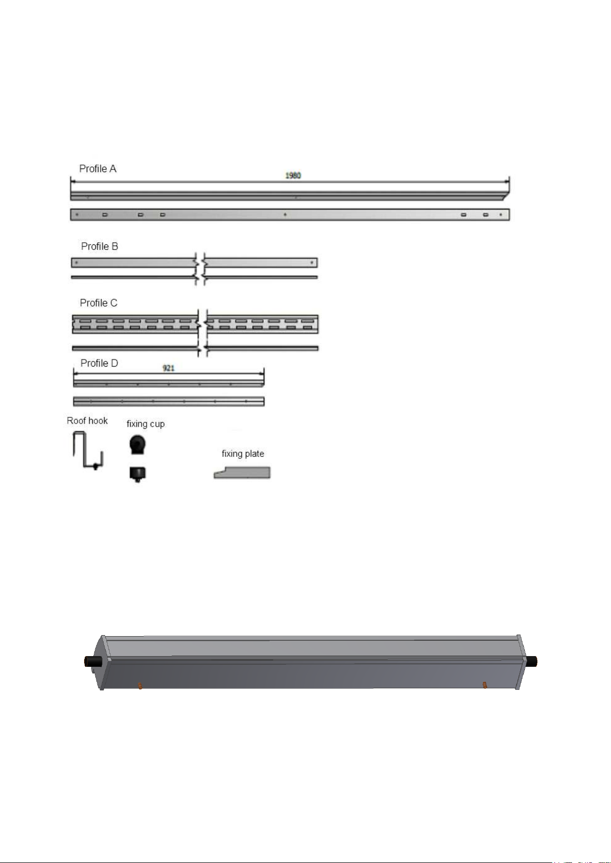
4.12 Evacuated tube collector on sloping roof
Fixing profiles:
The length of the fixing profiles various according to the number of evacuated tubes.
The image below shows the flow and return connections on the rear side of the collector
header.
return flow
14
Page 15

Atmos Heating Systems
Assemble the frame as shown:
Remove the tiles where the roof hooks are to be located. Place the roof hooks in the
valley of the tile and hook behind the roof batten.
The width of the frame can be adjusted to fit the position of the roof hooks. Determine the
location of the remaining 4 roof hooks and drill 8.5mm holes in the profiles A to fix the
roof hooks to the profiles A. After this the tiles can be replaced.
15
Page 16

Atmos EasySolar Installation Instructions Evacuated Tube Collector
Once the frame and the roof hooks have been fixed to the roof the header can be fitted to
the frame.
It is important that the header is fitted level, so that the water in the header drains
back correctly.
• Use an angle grinder to cut a section out of a roof tile.
• Cut two pieces of wakaflex each 50cm long.
• Use a hollow punch to make two 20mm holes in one of the two pieces of Wakaflex.
Fix the pipe gland to the holes. If the correct size hollow punch is not available it is
possible to use a 22mm compression ring instead.
• Place the wakaflex with the pipe gland over the tile with the section cut out and
underneath the tile higher up. Do not stick the wakaflex down till after the red and blue
collector pipes have been taken through the pipe gland.
• Place the second piece of wakaflex on top and above the first piece and underneath
the tiles higher up.
16
Page 17

•
Atmos Heating Systems
hot
cold
17
Page 18
Atmos EasySolar Installation Instructions Evacuated Tube Collector
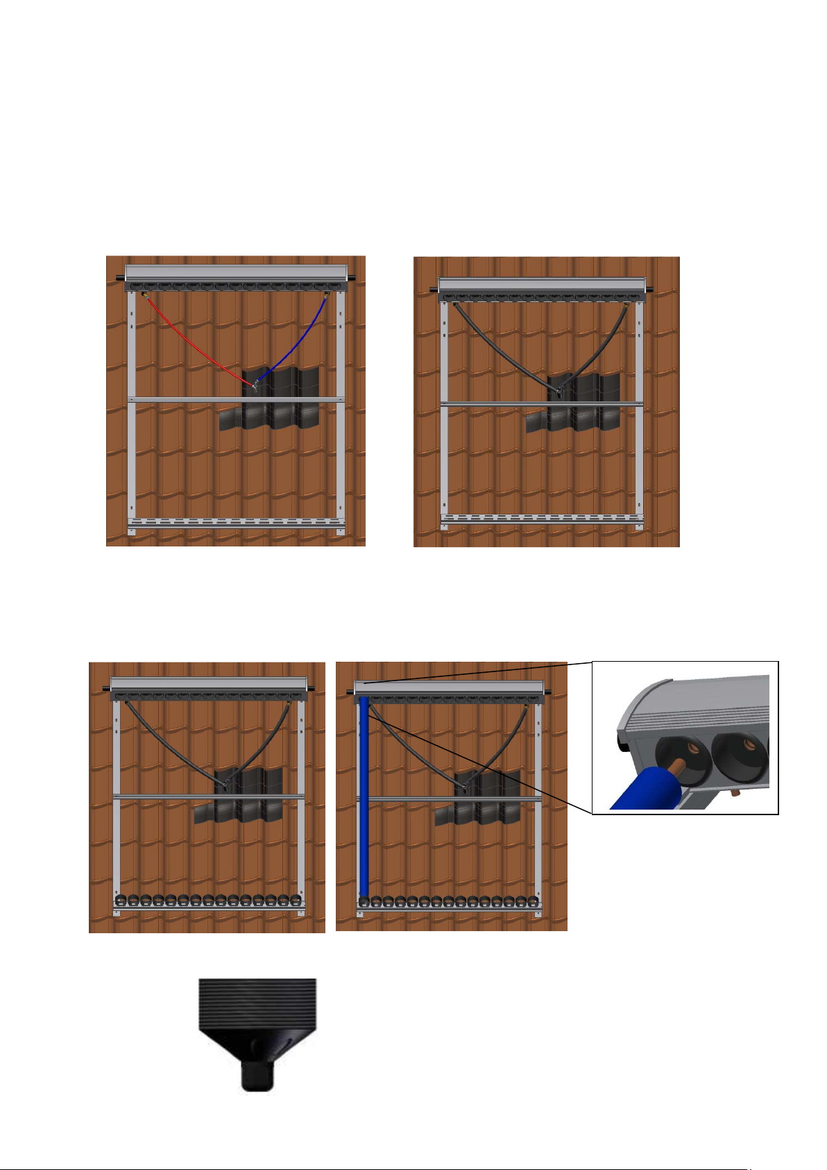
• Fit the compression elbows to the pipes coming out at the rear of the header.
• Connect the red and blue collector pipes and take these through the pipe gland.
Ensure that AT ALL POINTS THE PIPES SLOPE DOWN away from the collector
header.
• Fit the pipe insulation to the red and blue collector pipes.
• Ensure that there is enough slack in the pipes for thermal contraction (max 5%).
• Stick the wakaflex to the tiles.
• Fit the evacuated tubes and the fixing cups. Apply the heat transfer paste to the metal
ends of the glass tubes. Using soapy liquid on the ends of the glass tubes will make it
easier to slide them in.
Fixing cup:
18
Page 19

Atmos Heating Systems
End result:
The sensor cable from the collector header should be taken underneath the roof tiles and
down to the storage tank. The flow and return pipes must at all points slope down
towards the storage tank. This is essential in order for the water in the collectors and in
the pipes to flow back to the storage tank when the pump is not running. Ensure that
there is no tension on the flow and return pipes or leakage may occur. The red flow pipe
should be insulated along the whole of its length, using the pipe insulation provided. The
blue return pipe should be insulated only above roof level. The sensor cable can be
extended if necessary using a two wire cable.
19
Page 20

Atmos EasySolar Installation Instructions Evacuated Tube Collector
4.13 Evacuated tube collector on flat roof
• Assemble the frame. There are different options with regard to the angle of the
collector. The lowest possible angle is 35°.
• Place rubber tiles for roof protection underneath the frame.
• The horizontal L profiles for the ballast are needed when ballast is used. Ensure that
the L profiles are secured under the ballast and cannot slide free.
Fit the header to the frame and insert the glass tubes. Ensure that the header is level.
This is necessary so that the water in the header drains back correctly. Apply the contact
paste to the metal ends of the glass tubes. Soapy water can be used to make it easier to
slide the glass tubes into the sockets on the header.
20
Page 21

Put ballast on the four corners of the frame.
Minimum required ballast for 15 tube
Built up area
Open
12
335 274 226 482 397 226
The tables show the minimum
required ballast weight in kg
needed to secure the collector.
This applies for collectors at 35°
angle.
• Area I is an area of the country
prone to high winds.
• Area II is an area with medium
high winds.
• Area III has normal or moderate
winds.
collector
Height above
ground [m]
2
3
4
5
6
7
8
9
10
11
Atmos Heating Systems
countryside
Area I
Area II
Area III
Area I
Area II
Area III
255 207 169 255 207 169
255 207 169 283 207 169
255 207 169 321 245 169
255 207 169 350 274 169
255 207 169 378 297 169
255 207 169 402 321 169
255 207 169 421 335 169
255 207 169 435 354 169
283 231 188 454 369 188
312 255 207 468 383 207
21
Page 22

Atmos EasySolar Installation Instructions Evacuated Tube Collector
Minimum required ballast for
20 tube
Built up area
Open
Minimum required ballast for
24 tube
Built up area
Open
collector
countryside
collector
countryside
Height above
ground[m]
Area I
Area II
Area III
Area I
Height above
ground[m]
Area I
Area II
Area III
Area I
Area II
2
337 273 222 337 273 222
3
337 273 222 375 273 222
4
337 273 222 425 324 241
5
10
11
12
337 273 222 463 362 279
6
337 273 222 501 394 305
7
337 273 222 533 425 330
8
337 273 222 558 444 356
9
337 273 222 577 470 375
375 305 248 603 489 394
413 337 273 622 508 413
444 362 299 641 527 425
Area III
2
403 327 266 403 327 266
3
403 327 266 449 327 266
4
403 327 266 510 388 289
5
403 327 266 555 434 335
6
403 327 266 601 472 365
7
403 327 266 639 510 396
8
403 327 266 669 532 426
9
403 327 266 692 563 449
10
11
12
449 365 297 722 586 472
494 403 327 745 608 494
532 434 358 768 631 510
Area II
The ballast figures apply for a collector angle of 35°. Collector angles more than 35°
require greater ballast weight.
Area III
22
Page 23

Atmos Heating Systems
• Drill a 60mm hole in the roof
• Fit the compression elbows to the pipes coming out at the rear of the header.
• Connect the red and blue collector pipes.
• Take the red and blue collector tubes and the sensor cable through the pipe gland to
the storage tank.
• Ensure that AT ALL POINTS THE PIPES SLOPE DOWN away from the collector
header and also ensure that there is enough slack in the pipes for thermal contraction
(max 5%).
• Fix and seal the pipe gland to the roof using roof sealant.
• Fit insulation to the red collector tube along the whole of its length and to the blue
collector tube only above roof level.
• The pipes must be fixed sufficiently to prevent excessive movement on
occasions of strong wind.
23
Page 24

Atmos EasySolar Installation Instructions Evacuated Tube Collector
4.14 Filling the tank
The procedure for filling the storage tank with water is as follows:
Remove the plug from the overflow outlet and insert the overflow connector. Put a tray or
bucket underneath to catch any water coming out. Use the yellow hose provided for filling
the tank. Insert this into the filling connection point on the tank. Fill the tank slowly with
clean water.
Make sure the yellow hose is held firmly in position whilst water is flowing into the
tank.
Stop filling as soon as water flows from the overflow outlet. Allow the surplus water to
flow out before replacing the overflow plug and inserting the filling plug.
24
Page 25

Atmos Heating Systems
4.15 Flushing the pump
It is necessary to flush the pump in order to remove any air. The procedure for this is as
follows:
Connect the two connection points on the tank for the collector pipes with a short length
of pipe (can be either red or blue). Connect the two terminals on the sensor cable
connection point using a short piece of wire. Supply power to the storage tank through
the 12V adaptor. The pump will start running. Leave it running for one minute before
removing the short piece of wire and the short length of pipe.
4.16 Connecting the collector circuit
Connect the collector flow and return pipes to the connectors on the tank. To avoid leaks
ensure that the pipe ends have been cut square. Before connecting the blue pipe to the
tank, insert the flow restrictor to a depth of at least 3cm.
Connect the sensor cable from one of the collectors to the sensor cable connecting point
on the tank.
Fit the pipe insulation provided for this purpose to the red collector flow pipe along its full
length.
25
Page 26

Atmos EasySolar Installation Instructions Evacuated Tube Collector
4.17 Connecting the optional booster pump
A booster pump is a pressure activated pump which serves the purpose of increasing the
total pump height of the system. It must be fitted to the wall with the pipe connections at
the top. The booster pump must not be above the overflow level of the tank and not lower
than 500mm below this level. It is connected to the blue collector return pipe and it has its
own power supply through a 12V adaptor.
Note!
The flow restrictor is not fitted at the connection to the tank
but at the connection to the booster pump.
Flow restrictor
26
Page 27

Atmos Heating Systems
5 Maintenance
Storage tank
Annually check the sensor wiring and top up the tank. See §4.14
Collectors
Annually check the collector. Remove any debris and check that the collector is still firmly
fixed. Check that no water can leak through the roof.
Pipes
Do a yearly check on the pipes to ensure that the pipe insulation is still in place and
properly secured and that the collector pipes are correctly sloping down towards the
storage tank at all points.
Faults
The dial on the front of the tank gives an indication of the amount of heat stored in the
tank. If the storage tank is not collecting heat even though the sun shines this indicates a
fault.
To check for any malfunction follow the following procedure. This will only work when the
sun is shining.
Ensure the storage tank is cold by drawing off hot water. This may take 10 minutes if the
storage tank is very warm to start with.
1. Is there 240V on the socket? Yes=>2, No=>13
2. Is there 12V feed to the storage tank? Yes=>3. No=>4
3. Are the wires from the collector thermostat and the 12V feed to the tank connected
correctly? Yes=>6. No=>5
4. The 12V adaptor is faulty. Atmos can supply a replacement.
5. Ensure the wires are connected correctly. The wires from the collector thermostat are
interchangeable. Does the pump start up within 10 minutes? Yes=>6, No=>7
6. Does the red pipe become warm after a few minutes? No=>8
7. Disconnect the wires to the collector thermostat from the connector block on the tank
and then connect the two terminals on this block with a short piece of wire. Does the
pump start up? Yes=>9, No=>10
8. Unplug the 12V adaptor from the socket. Top up the tank with water. Plug the 12V
adaptor back into the socket. Does warm water begin to flow into the tank after a few
minutes? Yes=>12, No=>11
9. The collector thermostat is faulty or the wiring to the collector thermostat is
interrupted.
10. There is a fault with the storage tank pump or the wiring to the pump is interrupted.
11. Are the red pipe and the blue pipe to the collectors sloping back towards the storage
tank at all points? Yes=>14. No=>15
12. Check the system for leakage.
13. Ensure there is 240V on the socket.
14. Check the flow restrictors for blockages. There is one flow restrictor for each collector
and one for the storage tank.
15. Ensure that the red pipe and the blue pipe to the collectors are sloping back towards
the storage tank at all points. Flush the pump on the storage tank as described in
§5.15
27
Page 28
Atmos EasySolar Installation Instructions Evacuated Tube Collector
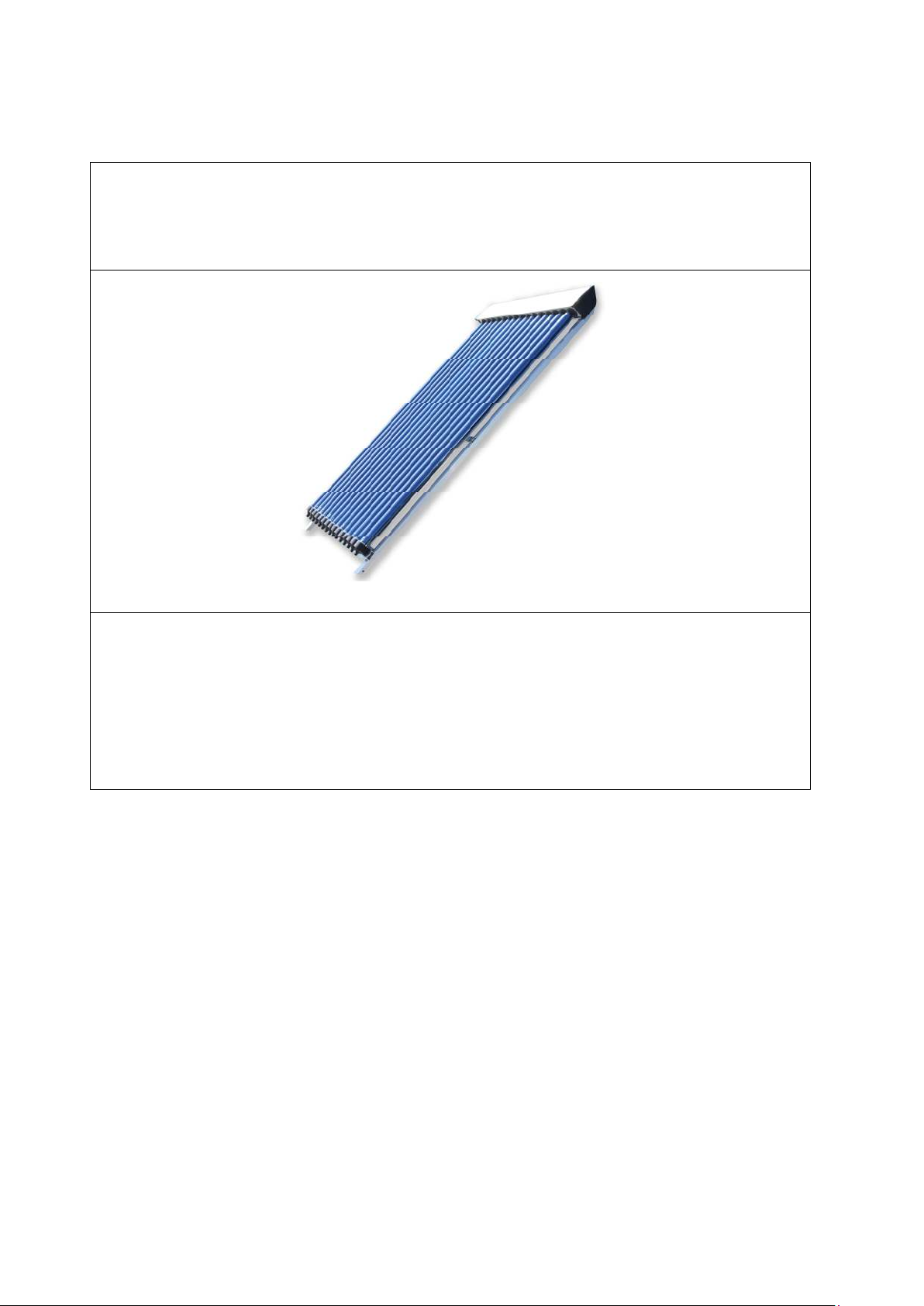
6 Technical specifications
Evacuated tube collector
Dimensions 15 tubes 1925 x 1184 x 135mm (length x width x height)
20 tubes 1925 x 1560 x 135mm
24 tubes 1925 x 1855 x 135mm
Installation angle (from horizontal) Between 20° and 80°
Absorber element Evacuated double glass tube
Frame material Aluminium
Pipes in collector header Copper
Test standard EN12975 / Solar Keymark
28
Page 29

Atmos Heating Systems
Storage Tank
General
Storage volume 100L
Weight empty 16 kg
Weight filled 116 kg
Domestic water sided
Content 1,5 L
Maximum pressure 800 kPa
Maximum temperature 80°C
Connections ½” BU
Pressure drop:
Collector sided
Content 98,5L
Medium clean drinking water
Maximum pressure no pressure
Maximum temperature 80°C
Connections 10mm dismountable
push-fit
Electrical
Power supply 12 V/DC
Dimensions
29
Page 30

Atmos EasySolar Installation Instructions Evacuated Tube Collector
7 Commissioning checklist
30
 Loading...