

Atmos DC 18 S, DC 40 SE, DC 22 S, DC 20 GS, DC 25 S Operating And Maintenance Instructions Manual
...Page 1

OPERATING AND MAINTENANCE
INSTRUCTIONS
ECOLOGICAL GASIFYING
BOILER
FOR WOOD
ATMOS
DC 18 S DC 22 S DC 40 SE
DC 20 GS DC 25 S DC 50 SE
DC 25 GS DC 32 S DC 75 SE
DC 32 GS DC 50 S
DC 40 GS
11/2002
Producer: Jaroslav CANKAŘ - ATMOS
Bělá pod Bezdězem
Tel.: +420 326 / 701 404, 701 414
www.atmos.cz
Page 2

WE WISH YOU ARE SATISFIED WITH OUR PRODUCT
AND THEREFORE WE RECOMMEND YOU TO KEEP
THE BELOW MENTIONED PRINCIPLES THAT ARE
IMPORTANT FOR THE LONG LIFE AND CORRECT
FUNCTION OF THE BOILER.
1. The used wood must be dry – max. 12 - 20 % of moisture – 2 years old.
2. During the gasification process the tars and acid condesates are produced. Therefore it is necessary to install Laddomat 21 behind the boiler in order to
keep the temperature of the water returning to the boiler not lower than
65 °C.
Operating temperature in the boiler should be 80 - 90 °C.
3. If the boiler is fitted with a circulating pump, the running of the pump must be
secured via a separate thermostat to ensure the minimal specified temperature of
the returning water.
4. The rated boiler capacity ensures its environmental friendly operation.
5. Therefore we recommend the installation of the boiler together with accumulating
tanks and Laddomat. This ensures lower fuel consumption (20 – 30 %) and longer
durability of boiler and chimney connected with more comfortable boiler
attendance.
6. If the boiler is operated at a derated power (water heating in the summer) a daily
firing-up is necessary.
7. The checking firing-up and the operational training must be carried out by a professional assembling company.
1
CAUTION! If the boiler is fitted with water accumulation tanks and Laddomat 21
(see the enclosed diagrams), the guarantee period of the boiler body is extended
from 12 to 36 months. In case of non-observance of these principles the boiler
body life and the durability of the ceramics shaped pieces will be reduced because
of low-temperature corrosion.
Page 3

1. Purpose
The ecological warm water boiler ATMOS is determined for heating in the one-family houses and
other similar buildings. The boiler types are used according to the required power output from 20 up to
75 kW.
The boilers are constructed especially for combustion of lump wood. All kind of dry wood can be used,
especially wood billets with the max. length 330 – 1000 mm according to the boiler type. Also wood
blocks with bigger diameter can be used, which reduces the nominal power but prolongs the burning
time. The boiler is not suitable for combustion of sawdust and wood waste – these can be used only in
small volume – MAX. 10 % - together with wood billets.
The huge fuel hopper will reduces the preparatory operations of the wood, because bigger billets can
be used. In this way, the physical effort can be eliminated and the time necessary for fuel cutting saved.
2. Technical data see page 3
Notice
The wood billets with bigger diameter must be divided into halves or quarters (according to the operating demands regarding the nominal power of the boiler). Hard and soft wood can be used.
The wood must be dry! The power output of the boiler depends on the moisture rate of
the wood. The power and the function of the boiler can be secured just if the moisture is
12 - 20 %.
3. Technical description
The boilers are constructed for combustion of wood. The combustion is based on the principle of
generator gasification using the exhaust ventilator, which blows the combustion air into the combustion
chamber.
The boiler body is a welded drum made of steel plates 3 – 6 mm thick, furthermore a fuel hopper with
a fire-resistant shaped piece in the lower part, which has a longitudinal hole for gas and waste gas flow.
The cumbustion chamber below is fitted with ceramic shaped pieces.
In the rear space of the boiler body there is a vertical fuel channel with a firing safety valve in the
upper space.The rear part of the main flue is equipped with a exhaust tube connected with the chimney.
The front of the boiler is fitted with a filling door upon an ash pan door.
The firing safety valve pull rod is situated on the upper front of the control panel.
The exterior of the boiler body is insulated with mineral felt placed under the outside metal jacket.
On the boiler top you will find the control panel for the elektrical-mechanical control.
At the back, there are the inlet channel for the primary and secondary air with a ventilator and a valve.
The primary and secondary air is pre-heated to a high temperature.
The boiler construction gives the following advantages:
The high temperature combustion with the generator function proceeds in a ceramic combustion
chamber with lateral primary air inlet into the boilers GS.
2
Page 4

3
2. Technical data
Boiler type ATMOS
DC 18 S DC 20 GS DC 25 GS DC 32 GS DC 40 GS DC 40 SE DC 50 SE DC 75 SE
Boiler power output kW 14-20 14-20 17-25 22-32 28-40 28-40 35-48 52-75
Heating surface m 1,8 1,9 2,7 2,9 3,2 3,5 4,2 5,2
Volumen des
Fuel container volume dm
3
66 87 130 130 170 190 252 345
Specified chimney draught Pa 16 18 23 23 23 25 25 30
Max. water working overpressure kPa 250 250 250 250 250 250 250 250
Boiler weight kg 293 350 408 415 453 460 545 700
Exhaust flue diameter mm 152 152 152 152 152 152 152 180
Boiler high mm 1120 1200 1200 1200 1350 1300 1300 1420
Boiler width mm 590 680 680 680 680 770 770 770
Boiler depth mm 845 845 1045 1045 1045 1045 1245 1390
El. protection class IP 20 20 20 20 20 20 20 20
Power input W 50 50 50 50 50 50 50 70
Boiler efficiency % 80-89
Max. noise level dB 65 65 65 65 65 65 65 65
Required fuel dry wood with caloric value 15 – 17 MJ.kg
water content 12 - 20 %, diameter 80 – 150 mm
Average fuel consumption kg.h
-1
3,5 3,8 6 7,2 10 10 13 18
in season 1 kW = 1 piled cubic meter
Max. billet length mm 330 330 530 530 530 530 700 1000
Water bolume in the boiler l 45 64 80 80 90 110 141 194
(specified min. temperature of the returning water during the operation: 65 °C)
Voltage V/Hz 230/50
Nominal heating power –
waste gas temperature °C 208 210 225 230 251 245 245 240
Nominal heating power –
waste gas mass flow kg/s 0,010 0,012 0,015 0,018 0,021 0,021 0,025 0,035
Water pressure mbar 0,18 0,22 0,22 0,22 0,23 0,22 0,18 0,24
Boiler class 3 3 3 3 3 3 3 3
Nominal heating power –
wood burning time 2 2 3 2 3 3 3 3
Range of adjustement
of the thermoregulator °C 75 ÷ 95
Dimensions of the filling hole mm (∅) 450 x 260 (∅) 450 x 260 (∅) 450 x 260 (∅) 450 x 260 (∅) 450 x 260 (∅) 450 x 260 (∅) 450 x 260 (∅) 450 x 315
Cool water pressure for
the safety heat exchanger °C/bar 20 > / 2
Page 5

4
Technical data
Boiler type ATMOS
DC 22 S DC 25 S DC 32 S DC 50 S
Boiler power output kW 15-22 17-25 24-35 48
Heating surface m 2,1 2,3 2,9 4,2
Volumen des
Fuel container volume dm
3
100 100 140 180
Specified chimney draught Pa 22 23 24 25
Max. water working overpressure kPa 250 250 250 250
Boiler weight kg 303 306 345 407
Exhaust flue diameter mm 152 152 152 152
Boiler high mm 1120 1120 1200 1200
Boiler width mm 590 590 680 680
Boiler depth mm 1045 1045 1045 1245
El. protection class IP 20 20 20 20
Power input W 50 50 50 50
Boiler efficiency % 80-89
Max. noise level dB 65 65 65 65
Required fuel dry wood with caloric value 15 – 17 MJ.kg
water content 12 - 20 %, diameter 80 – 150 mm
Average fuel consumption kg.h
-1
5 6 7,2 13
in season 1 kW = 1 piled cubic meter
Max. billet length mm 530 530 530 730
Water bolume in the boiler l 58 58 80 89
(specified min. temperature of the returning water during the operation: 65 °C)
Voltage V/Hz 230/50
Nominal heating power –
waste gas temperature °C 225 225 230 230
Nominal heating power –
waste gas mass flow kg/s 0,013 0,015 0,018 0,018
Water pressure mbar 0,21 0,21 0,20 0,22
Boiler class 3 3 3 3
Nominal heating power –
wood burning time 3 3 3 2
Range of adjustement
of the thermoregulator °C 75 ÷ 95
Dimensions of the filling hole mm (∅) 450 x 260 (∅) 450 x 260 (∅) 450 x 260 (∅) 450 x 260
Cool water pressure for
the safety heat exchanger °C/bar 20 > / 2
Page 6

WASTE GAS EXHAUST VENTILATOR = COMFORTABLE TEMPERATURE
The boiler generator is operated with a pre-heated primary and secondary air.The combustion is characterized through a warm constant flame with constant burning quality.
The big fuel hopper enables to burn the wood billets of max. length 330 – 1000 mm according to the
boiler type. large-lump wood waste can also be used.
The boiler is equipped with a cooling loop = security against overheating
4. Operating instructions
Diagramm and control elements of the boiler control panel
VARIANT A
VARIANT B
Control elements:
1. Safety thermostat 4. Waste gas thermostat - ventilator
2. Thermometer – outlet water 5. Operating thermostat - ventilator
3. Master switch – ventilator 6. Firing safety valve control
Function of the control elements:
1. The safety thermostat switches off the air distribution of the ventilator after exceeding the temperatu-
re 100 °C. For putting the ventilator into operation again the cover must be unscrewed and the button
pressed.
2. The thermometer shows the temperature of the outlet water from the boiler.
3. If the boiler is out of operation, the ventilator must be switched off via the master switch.
4. The waste gas thermostat is controlled according to the waste gas temperature in the exhaust flue. It
switches the ventilator after the burning out.
ATTENTION – On ignition, set the flue-gas thermostat to “0” °C (ignition). After stabilization of the
flame, set the flue-gas thermostat to “operation”. If flue-gas temperature drops bellow the set value
the thermostat will switch off the exhaust fan. If you want the fan to start the flue-gas thermostat
should be set to a lower temperature (set to “0” °C - ignition).
5. The operating thermostat switches the ventilator after reaching the outlet water temperature from the
boiler.The thermostat must be set at ca. 85-90 °C (mark on the thermostat body).
6. During the boiler operation the firing safety valve must be closed via its pull rod. The pull rod can be
pulled out only during the firing-up phase, filling the fuel, removing the ash.
Boiler preparation for the operation
Before putting the boiler into operation it is necesary to check, if the system is filled with water and
deaerated.
5
1
0
1
2345 6
OPEN
CLOSED
1
0
1
2
34 5
6
OPEN
CLOSED
Page 7

The boiler must be operated in accordance with these instructions to ensure the quality and the secure function of the boiler.The boilers are allowed to be attended only by adult persons.
During the assembly lay under the rear boiler part to 10 mm.
NOTICE
During the first firing up a condesation and a condensate outflow appears – it is no default.
In case of combustion of small waste wood the waste gas temperature must be checked – it is not
allowed to exceed 320 °C – this can cause a boiler damage.
The appearance of the tars and condensates on the fuel hopper is a normal process that accompanies the wood gasification.
Firing-up and operation
Before the firing-up the firing safety valve must be opened pulling out the pull rod /17/. Set waste gas
thermostat on zero.
Through the upper door /2/ put dry small firewood on the fire resistant shaped pieces /5/ perpendicular to the channel /12/ with a gap 2 - 4 mm between the fuel and the channel because of the flue gases
passage. Then paper or woody wool and small firewood again, after this bigger amount of dry wood.
After firing-up wait for max. 8 min., then switch on the ventilator /4/ and close the firing safety valve via
its pull rod /17/. On the power regulator /22/ set the required warm water temperature. After the firing-up
fill the fuel container with wood. Set the thermostat on 100-150 °C (on the point).
For the gasification it is necessary to establish and to keep a reduction zone of glowing charcoul on
the ceramic shaped pieces in the fuel container.This condition can be reached burning dry wood of adequate dimensions. If using wet wood, the boiler does not operate as a gasification boiler, the wood consumption is much higher, the required power output cannot be reached and the durability of boiler and
chimney will be reduced. The specified draught of the chimney ensures the boiler nominal power 70 %
even without a ventilator.
Power regulation – electrical-mechanical
The power output is controlled with a safety valve /8/ operated with the power regulator FR 124 /22/,
which automatically opens or closes the safety valve according to a set output temperature of the water
(80 – 90 °C). When setting the power regulator, much attention should be paidn to this activity, because
the regulator has another funtion else than power regulation – it also secures the boiler against overheating.
When setting this regulator HONEYWELL type FR 124, the enclosed installation and setting-up
instructions should be followed. The protection against overheating and the regulator function should be
checked at the water temperature 90 °C. In this stage the regulating safety valve /8/ must be nearly closed. The set point of the power regulator must be checked. The valve position can be seen at the back
of the ventilator. A controlling thermostat on the boiler control panel regulates the ventilator according to
the set temperature. A temperature on the controlling thermostat is to be set by 5 °C lower than that on
the power regulator FR 124. (A point marked on the thermostat scale). The working temperature of
water must be checked on a thermometer installed on the control panel.
Filling of wood
When filling the wood into the fuel container, following steps must be done: first open the valve /13/
with its pull rod /17/ (do not switch off the exhaust ventilator). Wait ca. 10 sec. and then open slowly the
filling door /2/ in such a way, that the cumulated gases flow into the gas flue. After this the filling door can
be fully opened. The fuel container shoul be filled completely. To eleminate the smoke escape, the filling
up should be performed after the wood is burned out at least to a third. Put a large billet on the glowing
charcoal and then fill up normally to minimize immediate burning out and production of the combustion
waste products. During the heating the firing safety valve /13/ must be closed – otherwise the ventilator
can be damaged.
6
Page 8
Operation with permanent glowing
It is possible to operate the boiler with permanent glowing, it means the fire can be kept during the
whole night without firing up every day. In the boiler the burning process can continue for more than 12
hours, therefore it is possible after a filling up of the wood and after switching on the ventilator to reach
in a short time the full power output of the boiler again. When operating the boiler with permanent glowing, the water temperature must remain at 80 – 90 °C.
Cleaning of the boiler
The cleaning of the boiler should be performed regularly and properly in a time interval of 3 – 5 days,
because the ash sediments in the fuel container reduce together with tars and condensates the life and
power output of the boiler and isolate the heating surface. In case of great volume of ash in the fuel container there is no sufficient space for burning, the holder of the ceramic nozzle and also the whole boiler
can be damaged.
Steps: First switch off the ventilator. In case, the boiler is equipped with an exhaust ventilator, this ventilator should run. Open the filling door /2/ and sweep the ash through the hole into the lower chamber.
The time interval of the cleaning depends on the wood quality (moisture) and heating intensity, chimney
draught (flue) and on other conditions. We recommend to clean the boiler once a week. Do not pull out
the fireclay shaped pieces during the cleaning process. For the boiler types DC 20GS, DC 25GS,
DC 32GS, DC40GS we offer an additional ash pan, which can be pushed in the lower round space
during the cleaning procedure.
7
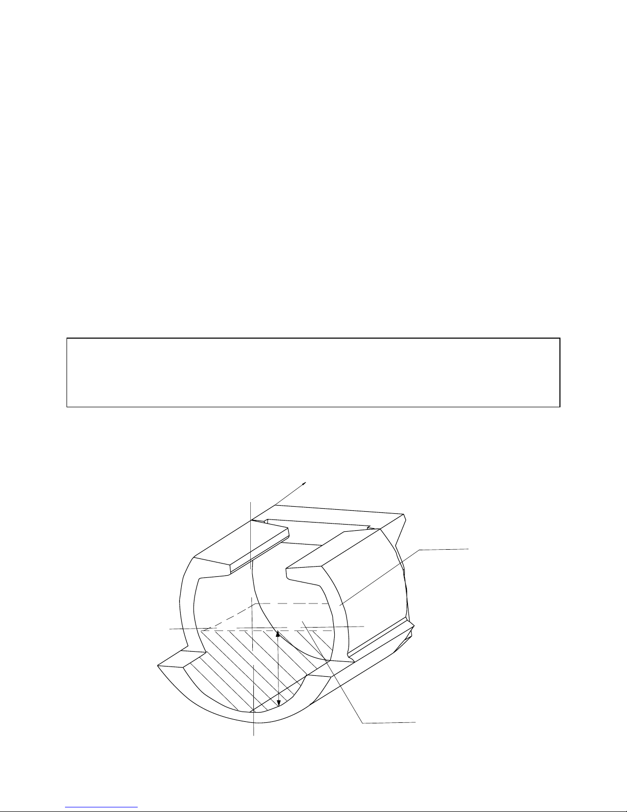
CERAMIC ASH COLLECTOR
REAR BOILER SPACE
CERAMICS
ASH
MAX. ASH VOLUME!
NOTICE:
The regular and proper cleaning is important to ensure the constant power output and long
durability of the boiler. In case of unsufficient cleaning the boiler can be damaged – the guarantee
becomes extinct.
100
Page 9

5. Maintenance of the heating system incl. boiler
The water in the heating system must be check and if necessary refilled at least once in 14 days. If the
boiler is out of operation during the winter, the water in the system could freeze. Therefore it is better to
drain the water off or to fill the heating system with an antifreezing solution.The water should be drained
off only if necessary and just for a very short time. When the heating season ends, the boiler must be
cleaned properly and damaged part are to change.
Twice a year dismantle the ventilator and clean the ventilator runner and the air chamber.
6. Fuel
The specified fuel is: dry wood billets and blocks with a diameter between 80 – 150 mm minimal
2 years old.The moisture 12 - 20 %. The length od the billets should be 330 – 1000 mm and the caloric
value 15 – 17 MJ.kg. The fuel dimenstions are stated in the article 2 „Technical data“. It is also possible
to burn large waste wood pieces together with wood billets.
7. Chimney
The connection of the boiler to the chimney flue must be carried out with agreement of an authorized
chimney-sweeping firm. The draught of the chimney must be for all operation types sufficient to draw off
the combustion gases into the free atmosphere.
It it necessary for the proper boiler function, that the chimney hole has the right dimension, because
the combustion, power output and boiler durability depend on the chimney draught. The chimney
draught depends directly on the section, high and on the surface roughness of the inside chimney wall.
It is not allowed to connect another appliances into the chimney used for the boiler.
The chimney diameter cannot be smaller as the flue hole on the boiler.
Recommended dimensions of the chimney:
20 x 20 cm min. high 7 m
diameter 20 cm min. high 8 m
15 x 15 cm min. high 11 m
diameter 16 cm min. high 12 m
The exact chimney dimension are stated in the standard DIN 1056.
The specified chimney draught is stated in the article 2 „Technical data“.
8
Maximum amount of ash is up to the level of the roof upper edge!
ASH
CERAMICS
Page 10

8. Boiler accessories
steel brush with accessories 1 piece
feed cock 1 piece
fire hook 1 piece
Operating and maintenance instructions,
quality and complete product certificate 1 piece
HONEYWELL Braukmann 1 piece
ash pan 1 piece
9. Electrical boiler connection
The electrical boiler connection is carried out with an electric cable with a plug 230 V and 50 Hz. The
boiler must be installed near an electrical socket. The electrical boiler connection must be performed
according to the valid regulations and standards.
10. Choise of the connection of the regulating
and control elements
The boiler is delivered with the standard equipment of regulating and control elements.The connection – see the diagram.
We recommend to complete the regulation with other regulating elements (room thermostat, pump)
to ensure a comfortable and economical heating system operation.The pump must be connected together with a thermostat in order not to cool the boiler in case of reverse run under 65 °C. The connection
of these other elements will be designed by a professional designer according to the specific conditions.
The electrical installation if these complementary elements must be carried out by a specialist in accordance with the valid standards DIN.
The basic boiler equipment has a thermostat connected with the pump 70 °C and 90 °C.
For Germany as land of destination is a water shortage protection necessary. This must be installed
by the customer/fitter.
11. Boiler protection
Using a mixing valve and a thermoregulating valve is a suitable solution of this problem.This enables
to create a separate boiler and heating (primary and secondary) circuit. The mixing ration and herewith
also the tempareture conditions in the boiler and heating circuit are determineted by the setting of the
mixing valve. The proper adjustment ensures the right mixing of the warm output water from the boiler
with the water to be returned so that the temperature of the returning water is over 65 °C. This
minimizes the condansation of water vapours, acids and tars in the fuel hopper. The mixing valve
enables through its suitable adjustment, that the regulation of the heating water temperature can be
carried out independent on the water temperature in the boiler.
As the position of the mixing valve flap and the temperature of the water streaming from the boiler
must be continuously regulated according to the requirements of the heating system and according to
the changes of room and outdoor temperature, it is necessary to install an electronic regulator.
The best boiler protection is to connect the boiler with an
accumulator and Laddomat.
The warranty and after-warranty service is carried out by:
ATMOS – Bělá pod Bezdězem
Cankař Jaroslav, 294 21 Bělá pod Bezdězem, tel: +420 326/701404
fax: +420 326 70 14 92 and by trade representation companies of ATMOS
9
Page 11

12. Possible defects and trouble shooting
Defect Cause Removal
pilot lamp „network“ does - no voltage in the network - to check
not burn - the plug is not pushed in the
socket properly - to check
- faulty switch - to change
- faulty cable - to change
The boiler does not reach - few water in the heating system - to refill
the required power and - too strong pump power - to adjust the pump
set water temperature (thermostat)
- the boiler power is not sufficient - design problem
for the respective warm water
system
- bad fuel quality (high moisture, - to use dry wood, to cut
billets to big) to billets
- leaky firing safety valve - to repair
- small chimney draught - new chimney,
the connection is not
suitable
- firing-up process too long or - to straighten to vanes
boiler operates with open firing (angle 90 °)
safety valve = vvanes of the
exhaust ventilator runner deformed
- the boile insufficient cleaned - to clean
Leaky door - faulty glass packing cord - to change
- small chimney draught - faulty chimney, connection
Ventilator does not run or - disconnection if using a non-reversible
is too noisy safety thermostat type TH 475.1- - to press the bottom on the
R105 AS5 thermostat
- the runner is dirty - to clean the ventilator, to
remove the tars and
sediments also from the
flue channel
- faulty condenser - replace
- faulty motor - replace
- bad contact in the plug of the motor
supply cable - check
13. Fire protection for the installation and use of thermal devices
Safety distances
When installating the boiler, the safety distance from the bulding materials of min. 200 mm must be
kept. This distance is valid for the boiler and flue gas ductings that are placed near inflammable materials class B, C1 and C2 (the inflammability classes are stated in the chart 1).
10
Page 12

The safety distance (200 mm) must be doubled, if the boiler and the flue gas ductings are installed
near inflammable materials class C3 (see chart Nr. 1). The safety distance is also to double if the inflammability class of the materials is not determined.
The safety distance is reduces to a half (100mm) using the thermal insulation plates (asbestos plates)
that are incombustible and min. 5 mm thick and are placed 25 mm from the protected inflammable material (fire-proof insulation). A insulating plate or protective screen (on the protected object) must overlap
contour of the boiler and flue gas ducting min. 150 mm on each side and min. 300 mm on the upper boiler surface. Also the equipment and facilities made of inflammable materials must be protected with
such a plate or screen, if it is not possible to keep the safety distance.
The safety distance must be also kept if storing some facilities near the boiler.
If the boiler is installed on a inflammable floor, an incombustable insulating footplate must be used.
This footplate shoul overlap the boiler contour min. 300 mm on the filling door side and min. 100 mm on
the other sides. For the thermal insulation the materials class A can be used.
Chart Nr. 1
The inflammability class Building materials and products according to
of building materials their inflammability class
and products
A – incombustible granite, sandstone, concrete, bricks, ceramic tiles,
mortar, fire protection plaster
B – uneasy inflammable akumin, izomin, heraklit, lignos, basalr felt boards,
glass fibre boards, novodur
C1 – heavy inflammable leaf wood (oak, beech), plywood, sirkolit,
werzalit, reinforced paper (umakart, ecrona)
C2 – medium inflammable conoferous wood (pine, larch, spruce), wood chip
boards, cork boards, rubber flooring (industrial, Super)
C3 – easy inflammable wood fibre boards (Hobra, Sololak, Sololit), cellulose
materials, polyurethan, polystyrene, polyethylene,
expanded PVC
NO
TICE
Under the circumstances that cause temporary higher danger of inflammable gases or vapours
production and during work operation that can cause fire or explosion danger (f.e. sticking the floor
covering – Linoleum, PVC) the boiler is to put out of operation. It is not allowed to put on the boiler
and to stock within the safety distance any objects and things made of inflammable materials.
11
Page 13

14. Flue gas ducting
The flue gas ducting must be connected to the chimney. If it is not possible to connect the boiler with
the chimney directly, the flue tube should be as short as posiible, not longer than 1 m, without any additional heating surface, and it must raise in the chimney direction. The flue gas ductings must have
mechanical strength, must be leak-proof against the combustion products and clean inside. The flue gas
ductings are not allowed to lead through the somebody else_s flats or utility rooms.
The inside diameter of the flue gas ducting must not be bigger then the inside diameter of the chimney flue and must narrow to the chimney. The use of elbows is not suitable.
15. Boiler environment
The boiler must be installed in a boiler room with sufficient air supply needed for the combustion. The
installation of the boiler in the habitable room inc. corridors is not acceptable.
16. Attendance and inspection
The boiler attendance is to be performed according to the operating and maintenance instructions. It
is not allowed to carry out such interventions that might threaten somebody’s health.
Only person over 18 years are allowed to attend the boiler.
It is not permitted to let children alone near an operating boiler.
When operating the boiler for solid fuel, it is forbidden to use inflammable liquids for firing-up. Farthermore it is not allowed to increase the nominal power of the boiler during its operation (overheating).
It is not permitted to put inflammable objects on the boiler and near the filling door and the ash pan
holes. The ash must be stored in incombustible containers with a cover.
The operating boiler must be controlled from time to time.
The user may perform only such repairs that contains just simple exchange of delivered spare parts
(for example ceramic shaped pieces, packing cord). During the boiler operation the leak-proofness of
the doors and cleaning holes must be checked icl. proper tightening. The user is not allowed to make
any intervention into the construction and electric installation of the boiler. The boiler must be cleaned
always proper and in time to ensure the passage capacity of all channels and flue gas ductings.The filling door and ash pan door must be always closed properly.
17. Binding standards for the boiler design and installation
DIN EN 303-5
DIN 4705
DIN 18160
DIN 4751-1
DIN 4741-2
DIN 4701
ONORM M 7550
The mixing fittings of Laddomat 21 a necessary element for the regulation of the central
heating. This ensures, that the temperature of the water returning to the boiler is
not lower than 65 °C, which prolongs the durability of boiler and chimney and reduces the
production of tars in the boiler. The boiler should be operated at a operating temperature nou
under 80 °C, otherwise the boiler life will be reduced - 2 years shorter durability.
The recommended temperature is between 80 – 90 °C.
12
Page 14

Considering the power output of the boiler we recommend to add 10 % for the potencial lower
fuel quality and higher moisture.
The boiler must be installed in such a way, that in case of a fall-out of electrical energy the
boiler is protected against overheating, otherwise the boiler might be damaged. To ensure the
max. durability of the boiler and chimney and the minimum of exhalations we recommend an
installation with accumulating tanks and Laddomat.
18. Spare parts
Fire resistant shaped piece – nozzle 5
Fire resistant shaped piece 10, 12, 14, 9
Ventilator 4
Switch with pilot lamp 20
Thermometer 18
Thermostat 24
Packing cord for the door 18 x 18 26
Safety thermostat 7
Nozzle sealing 11
Flue gas thermostat 27
Pump thermostat (70 °C) 28
Pump thermostat (90 °C) 29
Replacement of the fire resistant shaped
piece (nozzle)
Material list: 1. fire resistant shaped piece
2. packing cord
3. boiler cement
Procedure: Take out the resistant shaped piece (farther only nozzle) or smash it to pieces. Clean the
nozzle holder properly to remove the tar and old cement. Make thinline of the boiler cement and put
them on the nozzle holder round the hole so that the secondary air can not flow through the nozzle.Take
the nozzle in the hand, stand in front of the boiler, rotate the nozzle in the following orientation: the hollow must be farther from you and at the bottom /the hollow is orientated inside the boiler, the nozzle
mark – if there is any – at the back). In the rear boiler space the secondary air is conducted into the nozzle. Put the nozzle on the holder so that the clearance between tne nozzle and the holder all over constant is. Take the packing cord and form it by means of a hammer to a square or rectangle. Put the cord
round the nozzle (with narrow edge at the bottom) and bring it flush with the nozzle by slow, even hammering.
Replacement of the door packing cord
Procedure: take out the old cord by means with a screwdriver, clean the groove (slot). Form the packing
cord by means of a hammer to a square or rectangle Take the cord and press it round the door panel
(with narrow edge into the groove) and fix it (you can used the hammer). Take the door handle, put it up
and press the cord into the groove by slow slaming the door untill it is possible to close it. Only this process can ensure the proper tightness od the door.
13
Page 15

Door hinges and door closing
The filling door and the ash pan door are firmly connected with the boiler by means of two hinges. A
hinge contains a nut that is welded on the boiler body, adjusting screw and a pin for fixing the door. If you
wish to change the position of the hinges, first you must unlock and open the upper boiler cover (control
panel), take both pins out, take the door off and turn the adjusting screw according to need. Inverse process brings all into the original arrangement.
The door closing has a lever with a handle and a cam, which operates the wheel screwed in the boiler, and a safety nut that prevent from the rotation. After some time the packing cord in the door panel
will be squeezed so that the wheel must be screwed in more firmly. Loose the wheel nut and screw the
wheel into the boiler in that way, that the handle shows after closing the door on an imaginary clock 20
minutes.
19. Basic data concerning the wood combustion
We recommend to burn mostly dry wood. You can reach the maximal power output and boiler durability if burning min. 2 years old wood.
The following diagram shows the dependance of the water content on the fuel caloric value. This
value falls considerably with the increasing water content.
Example:
Wood with water content 20 % has the caloric value 4 kWh/ 1 kg wood
Wood with water content 60 % has the caloric value 1,5 kWh/ 1 kg wood
• Spruce wood after 1 year of shed storage
Max. boiler power output
if using this fuel:
DC 18 S - 13 kW
DC 20 GS - 14 kW
DC 25 GS - 19 kW
DC 32 GS - 24 kW
DC 40 GS - 31 kW
DC 50 S - 39 kW
DC 75 S - 54 kW
%
wood caloric value 1 kg
kcal kJoule kWh
spruce 3900 16250 4,5
pine 3800 15800 4,4
birch 3750 15500 4,3
oak 3600 15100 4,2
beech 3450 14400 4,0
Fresh wood has a low caloric value, does not burn good, produces smoke and reduces the durability of
the boiler and the chimney. The power output of the boiler will decrease to 50 % and the fuel consumption will increase to the double volume.
14
kWh/kg
Page 16

Legend to the boiler diagram
MODELLS 2002 - BOILER WITH EXHAUST VENTILATOR
15
1. Boiler body
2. Filling door
3. Ash pan door
4. Ventilator – pressure, exhaust
5. Fire resistant shaped piece – nozzle
6. Control panel
7. Safety thermostat
8. Regulating safety valve
9. Fire resistant shaped piece – furnace side
10. Fire resistant shaped piece – round
space
11. Sealing – nozzle 12 x 12
12. Fire resistant shaped piece - half-moon
13. Firing safety valve
14. Fire resistant shaped piece – rear round
space
15. Cleaning cover
16. Orifice plate – DC 18 S
17. Firing safety valve pull rod
18. Thermometer
19. Furnace orifice plate
20. Switch
22.Power regulator – Honeywell FR 124
23.Cooling loop
24. Ventilator thermostat
25. Door panel – Sibral
26. Doo sealing – cord 18 x 18
27. Waste gases thermostat
28. Pump thermostat 70 °C
29. Pump thermostat 90 °C
30. Shaped piece (roof)
Typ
ATMOS
DC 18 S DC 20 GS DC 32 GS DC 25 GS DC 40 GS DC 40 SE DC 50 SE DC 75 SE DC 22 S DC 25 S DC 32 S DC 50 S
A 1120 1200 1200 1200 1350 1300 1300 1420 1120 1120 1200 1200
B 690 690 890 890 890 890 1090 1390 890 890 890 890
C 590 670 670 670 670 770 770 770 590 590 670 670
D 872 946 946 946 1092 1046 1046 1153 872 872 946 1090
E 152 152 152 152 152 152 152 180 152 152 152 152
F 6575757575707075 65657575
G 200 180 180 180 180 180 180 180 200 200 180 180
H 930 1000 1000 1000 1137 1100 1100 1100 930 930 1000 1000
CH 220 255 255 255 255 305 305 305 220 220 255 255
I 190 240 240 240 240 290 290 290 190 190 240 240
J 6/4" 6/4" 6/4 "6/4" 2" 2" 2" 2" 6/4" 6/4" 6/4" 2"
Page 17

16
ATMOS
DC 18 S, DC 22 S, DC 25 S, DC 32 S,
DC 40 SE, DC 50 S, DC 50 SE, DC 75 SE
ATMOS GENERATOR
DC 20 GS, DC 25 GS, DC 32 GS, DC 40 GS
BOILER WITH EXHAUST VENTILATOR (S)
B
E
C
D
A
H
J
J
I
F
CH
G
30
Page 18

Type and installation of shaped pieces into the combustion chamber
1. For the type:
Shaped piece (roof) of the bottom combustion
chamber should always be pushed back against the
boiler rear wall.
27. Ceramics - roof.
(DC 22S, DC 25S, DC 32S, DC 40SE - 500 mm)
(DC 50S, DC50 SE - 700 mm)
2. F
or the type:
DC 75 SE The roof is composed of two pieces – see the figure.
(DC 75SE - 2 x 500 mm)
3. F
or the type:
Shaped piece (spherical space) should be assembled
in such a way that the front part of the shaped piece
(10) is 3 cm from the front edge of the boiler frame.
10. Ceramics – spherical space (L + R)
14. Ceramics – rear face
(Attention – during possible handling do not turn
the rear face)
In certain cases there boilers can also be fitted with
a spherical space instead of the roof.
17
DC 22 S
DC 25 S
DC 32 S
DC 50 S
DC 40 SE
DC 50 SE
DC 18 S
DC 20 GS
DC 25 GS
DC 32 GS
DC 40 GS
DC 40 SE
DC 50 SE
DC 75 SE
14
30
10
30
Page 19

HONEYWELL Braukmann
Heating power regulator FR 124
Installation instructions
Disassemble the lever (1)
and the joint (2).
Adjustment
Heat the boiler to the temperature ca. 80 °C. Set the regulating lever at the temparute which you can
read on the boiler thermometer. In case of vertical installation the white marking and white numbers are
valid.
Set the regulating lever at the temparute which you can read on the boiler thermometer.
Diagram of the exhaust ventilator
1 – motor
2 – plate
3 – runner
4 – nut the left-hand thread and washer
5 – wing nut
6 – screw
7 – large seal
8 – small seal
CAUTION! The exhaust ventilator is delivered in dismantled state. Put it on the rear smoke flue, tighten
properly, connect to the socket and check its smooth running.
18
cca. 3 - 50 mm
Adjustment of the primary and secondary air proportion
draught regulator
pull rod – adjustment of the
primary and secondary air
proportion
secondary air
supply
regulating valve (for the
boiler power output)
set value
stop
primary air
supply
Setting for the boilers DC
18
S - DC 40 SE (GS)
optimum: to the stop (5 mm) + 6÷10 mm
maximum: to the stop (5 mm) + 10÷12 mm
Setting for the boilers DC 50 SE
optimum: to the stop (12 mm) + 6÷10 mm
maximum: to the stop (12 mm) + 10÷12 mm
Setting f
or the boilers DC 75 SE
optimum: to the stop (20 mm) + 6÷10 mm
maximum: to the stop (20 mm) + 10÷12 mm
Page 20
19
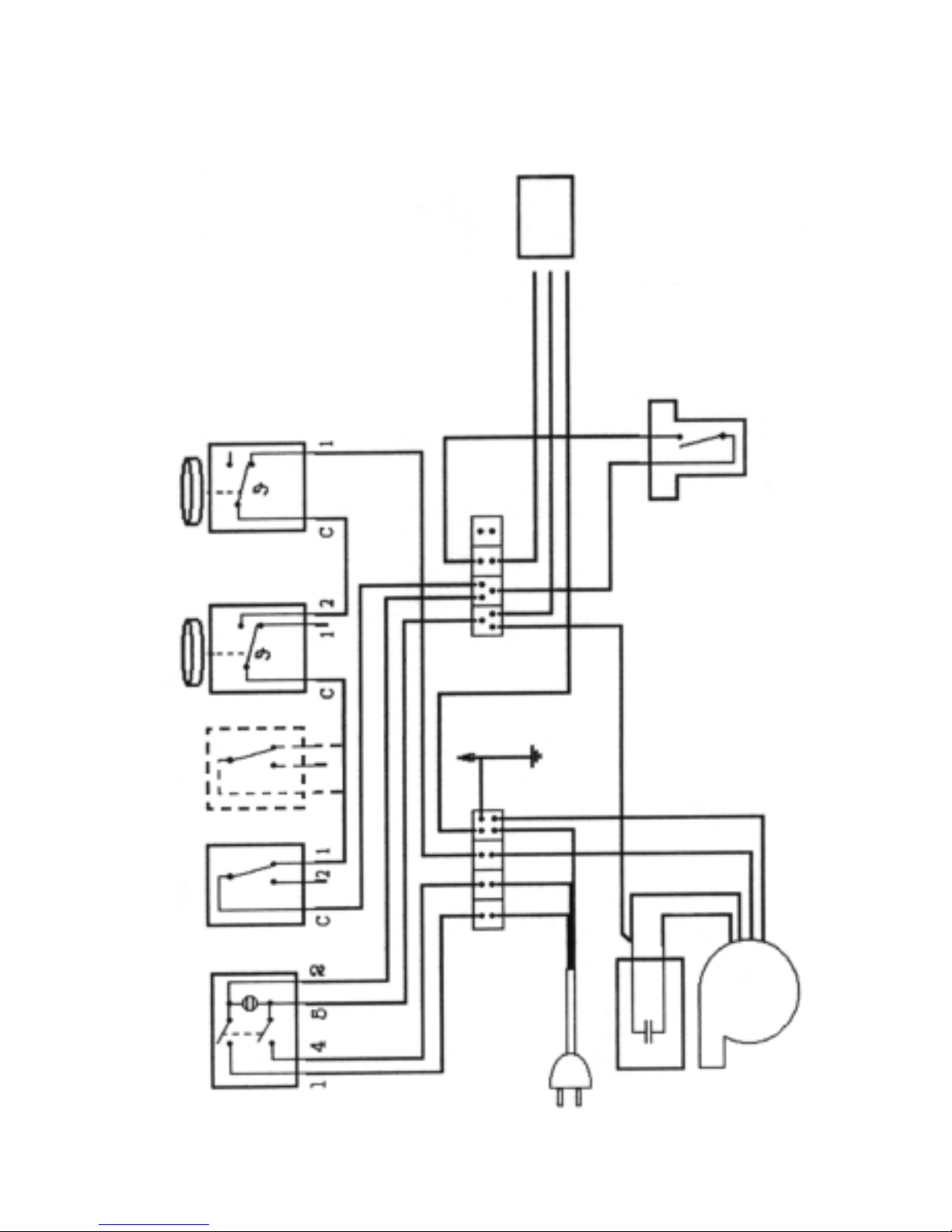
Switch
Safety
thermostat
Water
shortage
protection
Operating
thermostat
Combustion products
thermostat
Network
230 V 50 Hz
Ventilator
Condenser
brown
brown
Upper cover
yelow-green
yellow-green
yellow-green
blue
blue
blue
blue
red
black
black
black
black
black
Outlet
to
the pump
Pump thermostat 70 °C
The boiler has a combustion products thermostat and a pump thermostat 70 °C.
Installation Diagram mechanical regulation
with exhaust ventilator,Type UCJ 4C52, UCJ 4C82
(DC 18 S - DC 75 SE) (DC 20 GS - DC 40 GS)
Variant A
Page 21
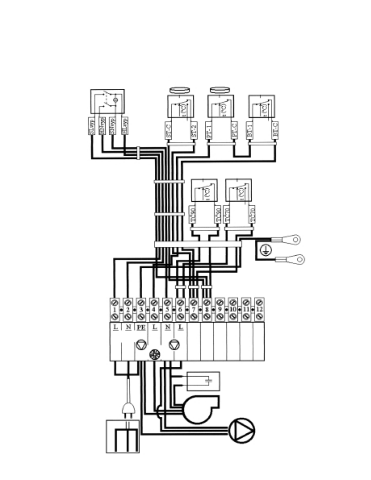
Installation Diagram mechanical regulation
with exhaust ventilator,Type UCJ 4C52, UCJ 4C82
(DC 18 S - DC 75 SE) (DC 20 GS - DC 40 GS)
Variant B
20
Cut-out switch
Flue-gas
thermostat
Process
thermostat
Pump
thermostat 90 °C
Pump
thermostat 70 °C
PE terminal board
PE hood
Condenser
Mains
230 V, 50 Hz
Process
thermostat
blue
blue
blue
blue
black
black
230 V/50 Hz
black
yellow-green
yellow-green
yellow-green
red
blue
blue
blue
blue
black
black
brown
brown
Page 22
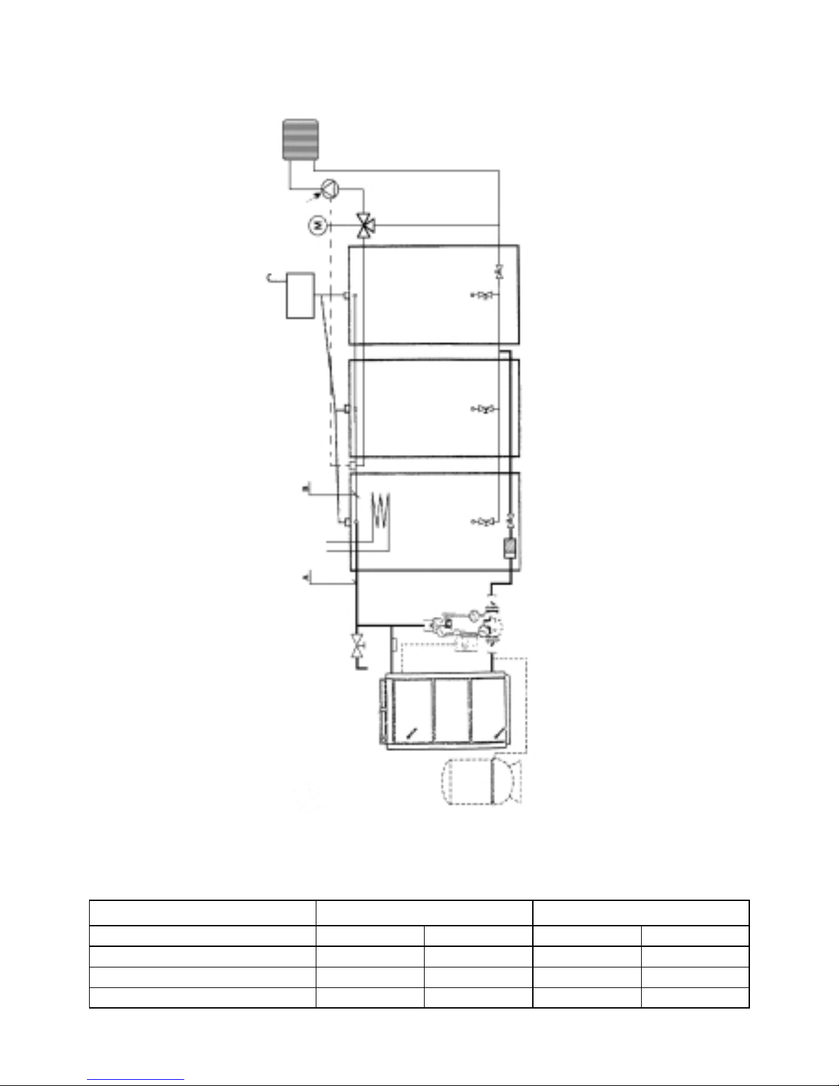
Installation diagram with LADDOMAT 21
and Accumulating tanks
21
Power output of Boiler Part A Part B
Copper Steel Copper Steel
18 - 25 kW 28x1 25(1”) 28x1 25(1”)
30 - 40 kW 35x1,5 32(5/4”) 28x1 25(1”)
50 - 75 kW 42x1,5 40(6/4”) 35x1,5 32(5/4”)
Pressure
expansion
tank
Laddomat 21
Filter
ATMOS
Safety valve,
air Release valve
Thermostat
70°C
Warm service
Water
Accumulating
tank
Accumulating
tank
Accumulating
tank
Open expansion vessel
Thermostat (40 – 60 °C)
Pump
3-way
Mixing
value
Habitable
rooms
Tubing diameter
for Installation with Accumulating tanks
Page 23

System operation with accumulating tanks
After firing up the boiler, it is operating at full power output (2 – 4 fillings) until the accumulating tanks
are completely at a temperature of 90 – 100°C. Then let consume all the fuel. Subsequently, the heat in
the accumulating tanks is consumed via a 3-way mixing valve.The time of this consumption depends on
the total volume of the accumulatings tanks and on the out-door temperature. In the heating season
(taking the minimum accumulating tanks volume into consideration), this period may be 1 – 3 days. If
using accumulation, we recommend min. 1 vessel (500 l) as expansion tank. It is used for boiler power
balancing.
Tank insulation
A good solution is to insulate all the accumulating tanks, up to the number necessary for obtaining
therequired volume, into one unit, with mineral wool on a frame of gypsum desks. Additionaly, loose
insulation material can be used. Minimum recommended thickness of mineral wool insulation is
120 mm. Another alternative is an insulation of separate tanks with polyurethane or mineral wool and
ST-foil in an artificial leather case.
22
BOILER PROTECTION AGAINST OVERHEATING
Boiler is fitted with a cooling exchanger and with a safety valve Honeywell TS 130-3/4A
(The temperature 95 °C opens the valve)
The safety valve TS 130 has a sensor placed on the boiler back, protects the boiler against overheating:
if the temperature in the boiler exceeds 95 °C, the water is supplied through the water inlet pipe into the
cooling loop – the water absorbs the excessive energy and then it flows off into the canalization.
TS 130
Filter
Waste
Water supply
ATMOS
Page 24

Laddomat 21
Laddomat 21 replaces with its construction
the normal installation of individual parts. It
consists of a cast iron body, a thermoregulating valve, a pump, a safety valve, ball valves
and thetmometers, when the temperature of
water in the boiler is 78 °C, the thermoregulating valve opens an inlet from a container. The
connection using the Laddomat 21 is much
easier, therefore we recommend it to you.
A spare thermo-cartridge for a temperature of
72 °C is supplied with the Laddomat 21 armature. Use it for boiler over 32 kW.
Laddomat 21 is intended for the output of
max. 75 kW.
Advantages:
The installation of the boiler with accumulating tanks result in a number of advantages:
- lower fuel consumption (20 – 30 %), the boiler operates at full power output and maximum efficiency,
until the fuel has burned out
- loger durability of boiler and chimney – production of tars and acids is minimized
- combination with other ways of heating is possible – e.g. electricity for heat accumulation
- combination of radiators with floor heating
- comfortable heating and perfect burning out of the fuel
- more ecological heating
23
Ball valve
1/4“
Ball valve
Thermo-valve
Wilo
RS 25/70
Thermometer
354
Safety valve
Thermometer
Ball valve
1 1/4“
Ball valve
1
1
/4”
OPERATING DATA
max. operating pressure 0,25 MPa
calculated overpressure 0,25 MPa
testing overpressure 0,33 MPa
max. operating temperature 100 °C
MINIMUM ACCUMULATING TANK VOLUME
power output/KW 20 25 32 40 49 75
Volume/l 1000-2000 1500-2000 2000-2500 2500-3000 3000-4000 4000-5000
Page 25

WARRANTY CERTIFICATE
for warm water boiler
type: ...................................................................... series/production year: .............................................
date of sale: ..............................................................
dealer’s stamp: ..........................................................
Unfilled warranty certificate is invalid
Warranty conditions:
1. If observing the purpose of use, operating and maintenance conditions stated in this instructions, we
warrant, that the product will keep the qualities complying with the technical standards and conditions
for the whole warranty period, it means 12 months since the date of the taking over of the product by
the customer and max. 20 months since the product has been sold by the producer to the dealer.
If the installation is carried out by a specialist, the warranty for the boiler body is 3 years, for other
parts 1 year.
2. If a defect appears during the warranty period, that wasn_t caused by the user, the product will be
repaired free of charge.
3. The warranty period extended according to the time during which the product have been in the war-
ranty repair.
4. The customer claims the warranty repair need during the warranty period in a service repair shop.
5. The service repair shop is obliged to remove the functional defects claimed by the customer free of
charge and in determinated time.
6. The buyer has been acquanted with the boiler use and operating.
7. The customer claims the after-warranty repairs also in a service repair shop. In this case, however,
the customer pais the repairs costs himself.
8. The user is obliged to follow this operating and maintenance instruction.The warranty becomes extin-
ct, if these instructions are not followed, if the boiler is operated with negligence or unprofessional
handling or if an unopproved fuel is burned. In that case, all repair costs are to be paid by the user.
9. The boiler must be checked incl. the setting of the control and structural elements by a professional
company min. once a year.This inspection must be notices and confirmed in this warranty cerfiticate.
24
Page 26

CERTIFICATION
ABOUT THE QUALITY AND COMPLETENESS OF THE PRODUCT
The warm water boiler, prod. number:........................ was checked before shipping.
The product complies with the required quality and is complete according to the enclosed product
documentation. The product is in conformity with the standard EN 303-5 and LGBL Nr. 33/1992.
Prepared for shipping on: Final test:
Date: Date:
The installation carried out by: Date:
25
Page 27

Records on carried out guarantee
and post-guarantee repairs
Repair: . . . . . . . . . . . . . . . . . . . . . . . . . . . . . . . . . . . . . . . . . . . . . . . . . . . . . . . . . . . . . . . . . . . . . . . . . . .
. . . . . . . . . . . . . . . . . . . . . . . . . . . . . . . . . . . . . . . . . . . . . . . . . . . . . . . . . . . . . . . . . . . . . . . . . . . . . . . . .
. . . . . . . . . . . . . . . . . . . . . . . . . . . . . . . . . . . . . . . . . . . . . . . . . . . . . . . . . . . . . . . . . . . . . . . . . . . . . . . . .
. . . . . . . . . . . . . . . . . . . . . . . . . . . . . . . . . . . . . . . . . . . . . . . . . . . . . . . . . . . . . . . . . . . . . . . . . . . . . . . . .
. . . . . . . . . . . . . . . . . . . . . . . . . . . . . . . . . . . . . . . . . . . . . . . . . . . . . . . . . . . . . . . . . . . . . . . . . . . . . . . . .
. . . . . . . . . . . . . . . . . . . . . . . . . . . . . . . . . . . . . . . . . . . . . . . . . . . . . . . . . . . . . . . . . . . . . . . . . . . . . . . . .
. . . . . . . . . . . . . . . . . . . . . . . . . . . . . . . . . .
Carried out by, date
26
Page 28

CONTENT
1. Purpose . . . . . . . . . . . . . . . . . . . . . . . . . . . . . . . . . . . . . . . . . . . . . . . . . . . . . . . . . . . . . . . . . . . . . . 2
2. Technical data . . . . . . . . . . . . . . . . . . . . . . . . . . . . . . . . . . . . . . . . . . . . . . . . . . . . . . . . . . . . . . . . . 3
3. Technical description . . . . . . . . . . . . . . . . . . . . . . . . . . . . . . . . . . . . . . . . . . . . . . . . . . . . . . . . . . . . 3
4. Operating instructions . . . . . . . . . . . . . . . . . . . . . . . . . . . . . . . . . . . . . . . . . . . . . . . . . . . . . . . . . . . 5
- Boiler preparation for the operation. . . . . . . . . . . . . . . . . . . . . . . . . . . . . . . . . . . . . . . . . . . . . . . . 5
- Firing-up and operation . . . . . . . . . . . . . . . . . . . . . . . . . . . . . . . . . . . . . . . . . . . . . . . . . . . . . . . . . 6
- Power regulation - electrical -mechnical . . . . . . . . . . . . . . . . . . . . . . . . . . . . . . . . . . . . . . . . . . . . 6
- Filling of wood . . . . . . . . . . . . . . . . . . . . . . . . . . . . . . . . . . . . . . . . . . . . . . . . . . . . . . . . . . . . . . . . 6
- Operation with permanent glowing . . . . . . . . . . . . . . . . . . . . . . . . . . . . . . . . . . . . . . . . . . . . . . . . 7
- Cleaning of the boiler . . . . . . . . . . . . . . . . . . . . . . . . . . . . . . . . . . . . . . . . . . . . . . . . . . . . . . . . . . 7
- Ceramic ash Collector . . . . . . . . . . . . . . . . . . . . . . . . . . . . . . . . . . . . . . . . . . . . . . . . . . . . . . . . . . 7
5. Maintenance of the heating system incl. boiler . . . . . . . . . . . . . . . . . . . . . . . . . . . . . . . . . . . . . . . . 8
6. Fuel . . . . . . . . . . . . . . . . . . . . . . . . . . . . . . . . . . . . . . . . . . . . . . . . . . . . . . . . . . . . . . . . . . . . . . . . . 8
7. Chimney. . . . . . . . . . . . . . . . . . . . . . . . . . . . . . . . . . . . . . . . . . . . . . . . . . . . . . . . . . . . . . . . . . . . . . 8
8. Boiler accessories . . . . . . . . . . . . . . . . . . . . . . . . . . . . . . . . . . . . . . . . . . . . . . . . . . . . . . . . . . . . . . 9
9. Electrical boiler connection . . . . . . . . . . . . . . . . . . . . . . . . . . . . . . . . . . . . . . . . . . . . . . . . . . . . . . . 9
10. Choise of the connection of the regulating and control elements . . . . . . . . . . . . . . . . . . . . . . . . . . 9
11. Boiler protection. . . . . . . . . . . . . . . . . . . . . . . . . . . . . . . . . . . . . . . . . . . . . . . . . . . . . . . . . . . . . . . . 9
12. Possible defects and trouble shooting . . . . . . . . . . . . . . . . . . . . . . . . . . . . . . . . . . . . . . . . . . . . . . 10
13. Fire protection for the installation and use of thermal devices. . . . . . . . . . . . . . . . . . . . . . . . . . . . 10
- Safety distances . . . . . . . . . . . . . . . . . . . . . . . . . . . . . . . . . . . . . . . . . . . . . . . . . . . . . . . . . . . . . 10
14. Flue gas ducting . . . . . . . . . . . . . . . . . . . . . . . . . . . . . . . . . . . . . . . . . . . . . . . . . . . . . . . . . . . . . . 12
15. Boiler environment. . . . . . . . . . . . . . . . . . . . . . . . . . . . . . . . . . . . . . . . . . . . . . . . . . . . . . . . . . . . . 12
16. Attendance and inspection . . . . . . . . . . . . . . . . . . . . . . . . . . . . . . . . . . . . . . . . . . . . . . . . . . . . . . 12
17. Binding standards for the boiler design and installation . . . . . . . . . . . . . . . . . . . . . . . . . . . . . . . . 12
18. Spare parts . . . . . . . . . . . . . . . . . . . . . . . . . . . . . . . . . . . . . . . . . . . . . . . . . . . . . . . . . . . . . . . . . . 13
- Replacement of the fire resistant shaped piece (nozzie) . . . . . . . . . . . . . . . . . . . . . . . . . . . . . . 13
- Replacement of the door packing cord . . . . . . . . . . . . . . . . . . . . . . . . . . . . . . . . . . . . . . . . . . . . 13
- Door hinges and door closing . . . . . . . . . . . . . . . . . . . . . . . . . . . . . . . . . . . . . . . . . . . . . . . . . . . 14
19. Basic data concerning the wood combustion . . . . . . . . . . . . . . . . . . . . . . . . . . . . . . . . . . . . . . . . 14
- Legend to the boiler diagram. . . . . . . . . . . . . . . . . . . . . . . . . . . . . . . . . . . . . . . . . . . . . . . . . . . . 15
- Boiler with exhaust Ventilator (S). . . . . . . . . . . . . . . . . . . . . . . . . . . . . . . . . . . . . . . . . . . . . . . . . 16
- Type and installation of shaped pieces into the combustion chamber. . . . . . . . . . . . . . . . . . . . . 17
- Honeywell Braukmann. . . . . . . . . . . . . . . . . . . . . . . . . . . . . . . . . . . . . . . . . . . . . . . . . . . . . . . . . 18
- Adjustment of the primary and secondary air proportion . . . . . . . . . . . . . . . . . . . . . . . . . . . . . . 18
- Diagram of the exhaust ventilator . . . . . . . . . . . . . . . . . . . . . . . . . . . . . . . . . . . . . . . . . . . . . . . . 18
- Installation Diagram mechanical regulation with exhaust ventilator - Variant A. . . . . . . . . . . . . . 19
- Installation Diagram mechanical regulation with exhaust ventilator - Variant B. . . . . . . . . . . . . . 20
- Installation Diagram with LADDOMAT 21 and Accumulating tanks. . . . . . . . . . . . . . . . . . . . . . . 21
- Boiler protection against overheating . . . . . . . . . . . . . . . . . . . . . . . . . . . . . . . . . . . . . . . . . . . . . 22
- System operation with accumulating tanks . . . . . . . . . . . . . . . . . . . . . . . . . . . . . . . . . . . . . . . . . 22
- Tank insulation. . . . . . . . . . . . . . . . . . . . . . . . . . . . . . . . . . . . . . . . . . . . . . . . . . . . . . . . . . . . . . . 22
- Laddomat 21 . . . . . . . . . . . . . . . . . . . . . . . . . . . . . . . . . . . . . . . . . . . . . . . . . . . . . . . . . . . . . . . . 23
- Warranty certificate . . . . . . . . . . . . . . . . . . . . . . . . . . . . . . . . . . . . . . . . . . . . . . . . . . . . . . . . . . . 24
- Certification about the Quality and Completeness of the Product. . . . . . . . . . . . . . . . . . . . . . . . 25
- Records on carried out guarantee and post-guarantee repairs. . . . . . . . . . . . . . . . . . . . . . . . . . 26
27
Page 29

Comments:
28
 Loading...