

Page 1

English
MedizinTechnik
ATMOS® Chair E 2
Operating Instructions
GA1 GB .130204.0
2017-10 Index: 05
Page 2

Table of contents
1.0 Introduction .........................................................3
1.1 Notes on operating instructions ............................3
1.2 Intended use .........................................................3
1.3 Function ................................................................3
1.4 Explanation of pictures and symbols ....................4
1.5 Scope of supply ................................................... 5
1.6 Transport and storage ...........................................5
2.0 For your safety ....................................................6
3.0 Setting up and starting up .................................7
3.1 Setting up ..............................................................7
3.2 Starting up.............................................................7
3.2.1 Front view .............................................................7
3.3 Electrical connection .............................................7
4.0 Operation .............................................................8
4.1 Positioning the patient...........................................8
4.2 Adjusting the seat height.......................................8
4.3 Rotating the upper part of the chair ......................9
4.4 Rotating the seat ...................................................9
4.5 Adjusting the manual backrest ............................10
4.6 Adjusting the electric backrest ............................10
4.7 Adjusting the arm rests .......................................10
4.8 Adjusting the head rest ....................................... 11
4.9 Foot rest .............................................................. 11
4.8 Chassis (optional) ............................................... 11
Further information, accessories, consumables and spare
parts are available from:
ATMOS
MedizinTechnik GmbH & Co. KG
Ludwig-Kegel-Straße 16
79853 Lenzkirch
Germany
Phone: +49 76 53 689-0
Fax:
+49 76 53 689-190
+49 76 53 689-493 (Service Centre)
atmos@atmosmed.de
www.atmosmed.de
5.0 Cleaning and care .............................................12
5.1 General information on cleaning and
disinfection ..........................................................12
5.2 Cleaning and disinfection of the device surface
and upholstery ....................................................12
5.3 Recommended surface disinfectants ..................12
5.4 Recommended disinfectants for the upholstery ..12
6.0 Maintenance and Service .................................13
6.1 Replacing the fuse ..............................................13
6.2 Sending in the device..........................................13
7.0 Troubleshooting ................................................13
8.0 Accessories and spare parts ...........................14
8.1 Accessories .........................................................14
8.2 Spare parts .........................................................14
9.0 Technical data ...................................................15
10.0 Disposal .............................................................16
11.0 Notes on EMC ....................................................17
2
Page 3

1.0 Introduction
1.1 Notes on Operating Instructions
These operating instructions contain important notes on how to operate the ATMOS® Chair E 2 safely,
correctly and effectively. Their reading helps to avoid risks, and also to reduce repair costs and downtimes. This increases, amongst other things, the reliability and service-life of the device.
These operating instructions serve not only for new operating personnel to be instructed in its use, but
also for use as a reference manual. Reprints (also in extracts) only with permission in written form by
ATMOS.
These operating instructions must always be kept available near the device.
Care and period tests in conjunction with professional execution provide for operational safety and
readiness for use of your ATMOS
Repair work and period tests may be carried out only by expert personnel authorised by ATMOS. By
applying only original spare parts you will have the guarantee that operational safety, readiness for work
and the value of your ATMOS
®
• The product ATMOS
medical products 93/42/EEC and meets the basic requirements of Appendix I of the directive.
• The product ATMOS
restricting the use of certain hazardous substances in electrical and electronic equipment (“RoHS”).
• The declaration of conformity and our general standard terms and conditions can be obtained on our
website at www.atmosmed.com .
• The quality management system applied at ATMOS has been certi ed according to international
standards EN ISO 13485.
• Prior to start-up please peruse chapter 2.0 „For your safety“, in order to be prepared for any possible
dangerous situations.
Chair E 2 bears CE marking according to the EC Directive of the council for
®
Chair E 2 complies with all applicable requirements of the Directive 2011/65/EC
®
Chair E 2 and are therefore a must besides regular cleaning.
®
Chair E 2 will be preserved.
1.2 Intended use
®
Name: ATMOS
Main function: This patient chair enables the optimum
positioning of the patient with regard to height and access.
Medical indications / application: Positioning of the patient
during standard ENT examinations and / or therapy.
Specifi cation of the main function:
• Electrical height adjustment via foot switch from 58.5 cm
up to 78.5 cm
• Upper part of the chair rotatable by 360 ° with lock on both
sides; with electric backrest 300 °
• Seats with integrated handles can be separately swivelled
to the right and left by 90°.
• In nitely variable inclination of the backrest from +7°
forward to the horizontal position (mechanical or electric)
• Height adjustable and detachable headrest
• Armrests can be folded up (individually)
• Foot support, can be swivelled synchronously with the
backrest
Application organ: Positioning of the patient
Application time: Temporarily (up to 60 minutes)
Application site: In clinics and practices for ENT doctors and
phoniatricians. The application of the doctor’s chair must be
executed by medically trained persons only.
Contraindications: None
Chair E 2
The product is: active
Sterility: Not necessary
Single-use product / reprocessing: No single use product
1.3 Function
The patient chair is equipped with an electromotive height
adjustment from 58.5 cm to 78.5 cm. The seat height
adjustment is controlled by a foot switch. On request the Auto
- Down (homing) function drives the chair automatically to its
lowest position. The upper part of the chair can be xed in
any position by means of a locking brake with locking levers
attached on both sides. Optionally it is possible to move the
patient chair effortlessly by means of the integrated chassis.
The high backrest is steplessly adjustable from approx. 7°
to the horizontal. The height adjustable neck support can
be easily removed. The seat is separately rotatable by 90 °
to the right and left and is easily xed by a ball screening in
central and end position.
3
Page 4

1.0 Introduction
1.4 Explanation of pictures and symbols
Short cuts / symbols contained in these operating instructions
■
Please press where
dot indicates
Please read,
important information
Graphic symbols contained in these operating instructions
Warning, special diligent notice
●
→
General informationFollow the arrows
Numeration
Sub-numeration
Check
!
Symbols of ATMOS
®
Chair E 2
click
Important information
Move, plug... in this
direction
Turn, shift ... in this
direction
Replace
Engage, check
correct t
Degree of protection type B
REF
Order number
This product complies with the relevant
requirements of EU Directives
Alternating current
~
4
Page 5

1.0 Introduction
1.5 Scope of supply
Prior to dispatch, the ATMOS® Chair E 2 was subjected to an extensive functional test and was carefully packed.
Nevertheless, please compare the contents of the shipment on completeness immediately upon receipt (see delivery note).
Basic device
Operating
Instructions
Power cable
1.6 Transport and storage
• After the transport of the device in temperatures below
0°C or prior to rst start up it should be kept at room
temperature for at least six hours. If the device is not
acclimatized it may not be used as damages to the
electronic components may be the result.
• Only transport the device in a shipping carton, which is
padded and offers suf cient protection.
• If damage occurs during transport:
- Document and report the transport damage.
- Send the device to ATMOS (Chapter „6.2 Sending in
the device“ on page 13).
Ambient conditions:
• Transport / storage:
- -10...+50°C;
- 30...95 % air humidity without condensation
- at an air pressure of 500...1060 hPa
• Operation:
- +10..+35°C;
- 30...95 % air humidity without condensation
- at an air pressure of 500...1060 hPa
5
Page 6

2.0 For your safety
!
For your safety
• The Chair E 2 has been designed in accordance with IEC
601/ EN 60601. The equipment conforms to VDE Safety
Class I and must only be connected to a properly installed
earthed socket.
• The Chair may only be used in supervised operation (IEC
60601-1 / EN 60601-1).
• Prior to rst start up, check whether the supply voltage
indicated on the chair corresponds to the value of your
local power supply.
• For mains supply, only use the power cable supplied (or an
equivalent one).
• Check proper assignment when assembling country-
speci c connections:
- green / yellow: protective conductor
- blue: neutral conductor
- black or brown: phase
• Prior to rst starting up, all connecting leads must be
checked on damage. Damaged cables must be replaced.
• To disconnect the chair from the power supply, rst
remove the plug from the safety connection socket. Then
disconnect the connection line from the chair. Never touch
plug or cables with wet hands.
• Please observe the ambient conditions stated in the
technical data (chapter 7.0).
• The Chair E 2 is not designed for the use in medical areas
with an explosion hazard. Explosion-hazardous areas
may be caused by the use of ammable anaesthetics,
skin cleansing products and skin disinfectants.
• Ensure that the patient sits in the middle of the seat. A
constant unilateral strain on the seat can damage the
surface.
• The user must be familiar with the operation of the chair.
• ATMOS is not liable for personal injury and damage to
property if
- no original ATMOS parts are being used,
- the advice for use in these operating instructions is not
being observed.
• Please note:
A medical insulating transformer with earth leakage
monitor or any similar safety system acc. to EN 60 601-1
is required, if several devices are connected over one
common power supply. The transformer must correspond
to the power consumption of all the devices to be
connected.
• The electric motor is protected by an integrated thermal
protection switch. After 1.5 minutes of continued
operation, the motor requires a cool down period of
approx. 8.5 minutes. If the thermal protection switch
is activated, the motor requires a cool down period of
approx. 20 minutes.
6
Page 7

3.0 Setting up and starting up
3.1 Assembly
• Always place the device on a level, safe surface.
Mains voltage and fuse:
Mains voltage: 230 V / 50 Hz (120 V / 60 Hz)
Fuse:
• Thermal fuse: 3 A (230 V)
• Thermal fuse: 6 A (120 V)
3.2 Starting up
• Position the chair at the allocated space. Any oor
unevenness must be compensated for.
• Check that the upper part of the chair can rotate freely.
• Peruse safety information in part 2.0 prior to starting up the
device for the rst time.
• Finally, connect power cable.
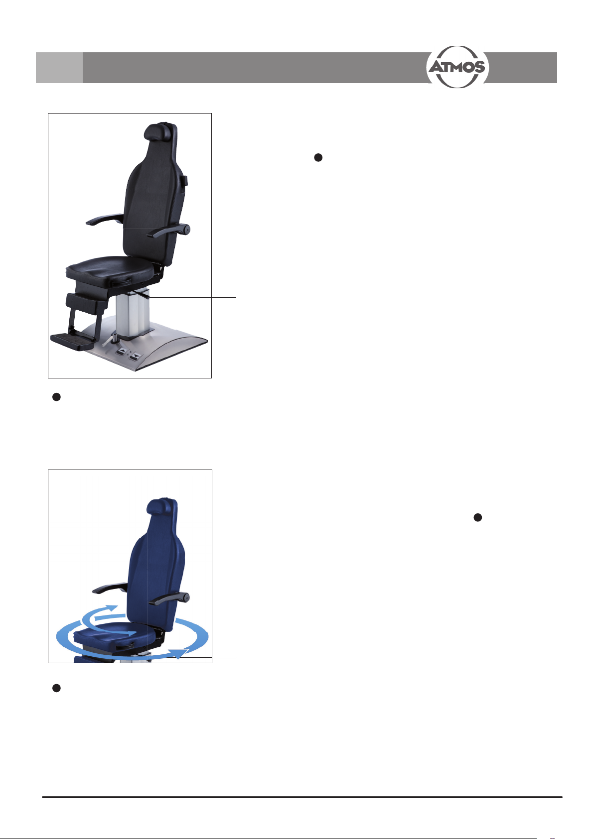
3.2.1 Front view
Fig. 1.
Individually adjustable headrest
1
Lever for in nitely variable synchronous adjustment of
2
the backrest, arm rests and foot support
Arm rests can be folded backwards
3
Rotary seat
4
Lever for arresting the rotatable upper part of the chair
5
Swivelling foot support
6
Foot switch for adjusting the seat height
7
3.3 Electrical connection
The ATMOS® Chair E 2 is supplied with a power cable and
IEC connection. The power cable is plugged into the IEC
connection on the rear side of the base and is connected to a
properly installed earthed socket.
The electrical connection values (voltage and nominal
frequency) as well as the data for fuses can be found on the
type plate above the connecting socket.
Disconnection from the power supply is only possible by
pulling the power plug!
There is no indication that the device is powered!
In the case of non-use, service and repair work and
cleaning, the chair must be disconnected from the power
supply by pulling the power plug.
7
Page 8

4.0 Operation
The height adjustment is controlled via the two foot switch
buttons marked with arrows. The left foot switch button is
for the upwards movement, the right for the downwards
movement.
The arm rests can be folded backwards; that makes it
easier for handicapped persons to be transferred from the
wheelchair to the examination chair.
The backrest inclination can be controlled by means of the
control elements attached to the side of the backrest.
Arm rests, foot support and backrest are coupled for
synchronous movements.
The electric motor is protected by an integrated thermal
!
protection switch. After 1.5 minutes of continued operation,
the motor requires a cool down period of approx. 8.5 minutes.
If the thermal protection switch is activated, the motor
requires a cool down period of approx. 20 minutes.
4.1 Positioning the patient
Ensure that the patient sits in the middle of the seat.
A constant unilateral strain on the seat can damage the
surface.
Fig. 2.
4.2 Adjusting the seat height
The seat height adjustment is controlled by the 2 foot
switches ( g.2):
Furthermore, the ATMOS patient chair features an “Auto –
Down (homing)” function, driving the seat down to its lowest
level after a short tap on the foot switch. Pressing the right
foot switch
to home position. To stop the movement, just brie y tap the
button again.
= Up
= Down
for less than 0.5 seconds will move the chair
8
Page 9
4.0 Operation
4.3 Rotating the upper part of the chair
The upper part of the chair with the patient can be completely
rotated after having loosened the brake with the locking lever
1
, g. 3).
(
The upper part with the patient can then be rotated in the
desired direction.
If the brake is only slightly xed the chair can be rotated
without loosening the brake.
The rotating angle is limited for chairs with an electric
backrest adjustment. In this case the chair can be rotated by
150° either to the right or to the left.
Fig. 3.
1
Locking lever
Fig. 4.
1
Locking lever
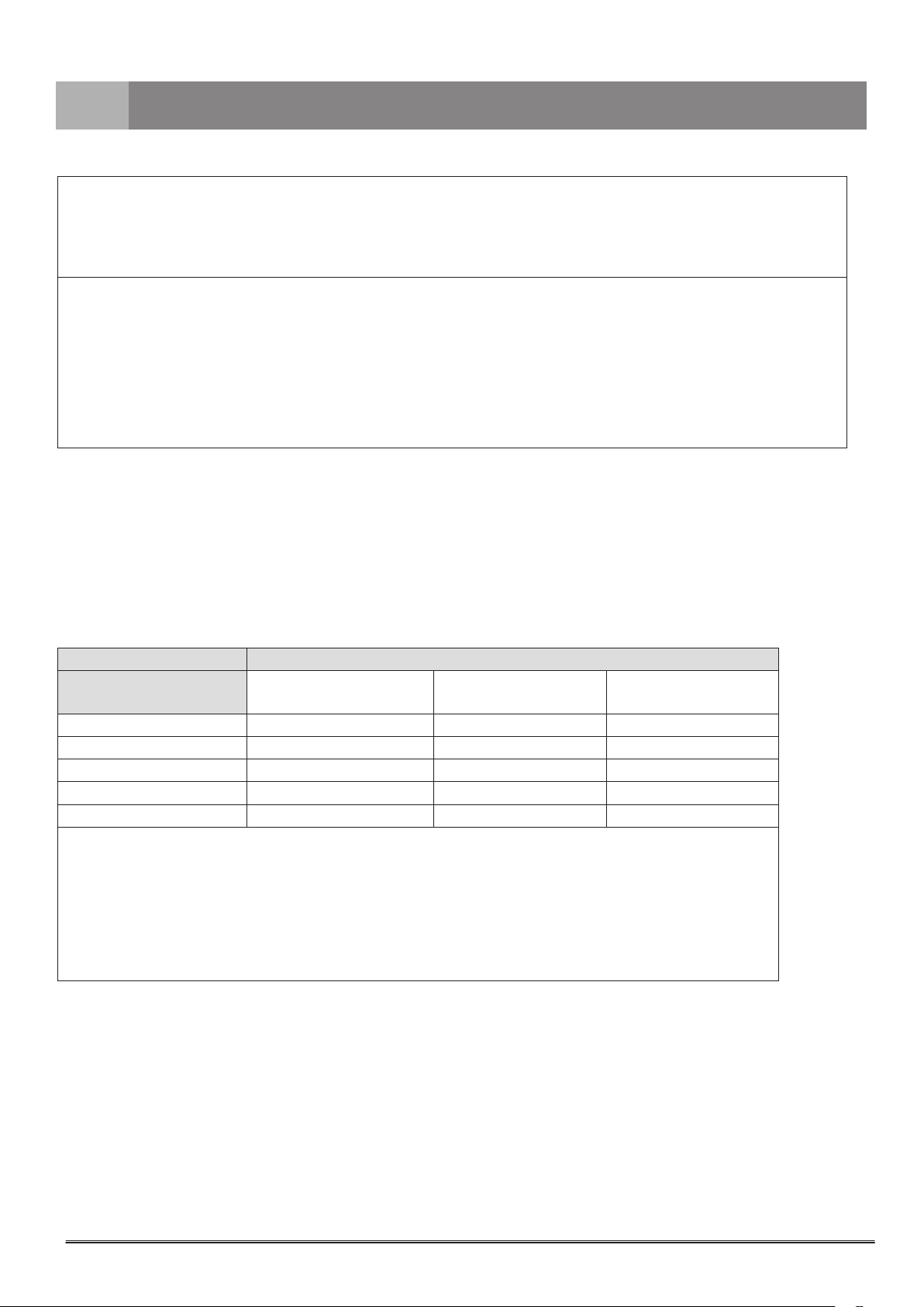
4.4 Rotating the seat
The seat with the patient can be rotated independent of a
backrest movement.
1
To do so, adjust the lateral locking lever (
its central position. The seat can then be rotated 90° to the
left or 90° to the right. When the locking lever is brought into
the central position, the seat surface is easily xed both in
position 90° to the left and 90° to the right, and engages in
the central position.
, g. 4) beyond
9
Page 10

4.0 Operation
Fig. 5.
1
Lever element
4.5 Adjusting the manual backrest
• Press lever element (1, g. 5) downwards.
• Adjust backrest to the desired position.
• Release lever element which will then return to its initial
position.
• Backrest and foot support are arrested.
Arm rests, base part and back rest are coupled for
synchronous movements.
4.6 Adjusting the electric backrest
Arm rests, base part and back rest are coupled for
synchronous movements.
®
The ATMOS
electric backrest.
The adjustment is possible both by means of a foot switch (
, g. 6), as well as by rocker switches attached to the side of
the backrest. When the backrest is raised from the horizontal
or the backstop, a rst holding point is installed when the
backrest is in the vertical position. To move the backrest to
the 10° forward position, press any of the switches again.
Chair E 2 can optionally be equipped with an
1
Fig. 6.
1
Foot switch
Fig. 7. Arm rests
4.7 Adjusting the arm rests
The arm rests ( g. 7) can be individually folded backwards.
10
Page 11

4.0 Operation
Fig. 8. Headrest
4.8 Adjusting the head rest
The head rest ( g. 8) can be brought into a lower position
by simply pulling the retaining strap into a lower position or
by pushing it into a higher position. To remove the headrest,
the retaining strap must be pulled out completely from the
backrest.
4.9 Foot rest
If required, the foot rest can be folded down ( g. 9).
Fig. 9. Foot rest
Fig. 10.
Fig. 11. Fig. 12.
4.10 Chassis (optional)
Do not transport any weights or persons on the chair.
!
The chair may be moved as soon as the red LED light
illuminates.
Clearance height: ca. 15 mm.
Extend the chassis:
• Move the chair upwards
illuminates (
• Push the lever to the left
chassis.
• Move the chair downwards
illuminates (
The chair can now be moved.
Retract the chassis:
• Move the chair upwards
illuminates (
• Push the lever forward
chassis.
• Move the chair to the desired position
LEDs (fi g. 10)
1
Red: Extend the chassis, chair can be moved.
2
Green: Lever can be adjusted.
Lever position (fi g. 11 + 12):
Only adjust the lever when the green LED is illuminated.
Otherwise the chair can be damaged.
3
Forward: Retract the chassis
4
Left: Extend the chassis
2
, g 10).
1
, g 10).
2
, g 10).
until the green LED
(4, g. 12) to extend the
until the red LED
until the green LED
(3, g. 11) to retract the
/ .
11
Page 12

5.0 Cleaning and care
5.1 General information on cleaning and disinfection
Prior to cleaning
Medical chairs like the ATMOS® Chair E 2 must always be operational and reliable.
Therefore, we recommend:
Prior to each use:
if required
The described measures relating to cleaning and
disinfection resp. sterilisation do not replace the relevant
instructions which must be adhered to prior to operation!
• For disinfection, you may use all surface and upholstery
disinfectants listed in chapter 5.3 and 5.4 “Recommended
disinfectants”.
Always observe the concentration speci cations and
instructions by the respective manufacturer!
• Do not use
- Disinfectants which contain organic or inorganic acids
or bases as they could cause corrosion damage.
- Disinfectants containing chloramides, phenol
derivatives or anionic tensides, as these may cause
stress cracks in the material used for the housing of the
unit.
5.2 Cleaning and disinfection of the device surface and upholstery
If liquid has penetrated the device, it may not be operated again until it has been checked by the authorised customer service
centre.
• The surface of the ATMOS Chair E 2 is resistant against all the recommended surface disinfectants stated in chapter 5.3
!
and 5.4. Nevertheless after a longer period of use discolouration could occur. Polar solvents (e.g. acetone or chlorinated
hydrocarbons (CC)) may not be used for cleaning and disinfection.
• Disconnect the power plug from the power supply prior to cleaning and disinfecting the device surface.
• The device itself can be wiped off with a moist (not wet) cloth.
• Substances such as blood must be removed immediately to prevent stains.
Do not use aggressive or abrasive cleansing agents. For the upholstery standard dry foam may be used.
!
Treatment with a commonly used care product for arti cial leather is recommended once a week in order to keep the upholstery
soft and smooth.
5.3 Recommended surface disinfectants
The surfaces of the ATMOS® Chair E2 can be cleaned / wiped with disinfectants containing the following active ingredients:
• QAV (quaternary ammonium compounds)
5.4 Recommended disinfectants for the upholstery
Disinfectant Ingredients in 100 g Manufacturer
Green & Clean SK Di alkyl dimethyl ammonium chloride < 1 g Metasys, Rum (Austria)
Alkyl dimethyl ethyl benzyl ammonium chloride < 1 g
Alkyl dimethyl benzyl ammonium chloride < 1 g
12
Page 13

6.0 Maintenance and Service
Maintenance, repairs and period tests may only be carried out
by persons who have the appropriate technical knowledge
and are familiar with the product. To carry out these measures
the person must have the necessary test devices and original
spare parts.
ATMOS recommends: Work should be carried out by an
authorized ATMOS service partner. This ensures that repairs
and testing are carried out professionally, original spare parts
are used and warranty claims remain unaffected.
®
The ATMOS
possible fuse change (see section 6.1).
Nevertheless, should a malfunction occur, please inform the
authorized ATMOS customer service immediately.
• At least every 24 months a repeat test of the electrical
safety should be performed according to IEC 62353.
• ATMOS recommends an inspection according to the
manufacturer‘s speci cations.
Chair E 2 is maintenance-free except for a
6.1 Replacing the fuse
Before replacing the fuse, unplug the power plug.
• To open the fuse holder turn counter clockwise.
• Exchange the fuse.
• To close the fuse holder, turn clockwise.
6.2 Sending in the device
• Remove and properly dispose of consumables.
• Clean and disinfect the product and accessories according
to the operating instructions.
• Place used accessories with the product.
• Fill in the form QD 434 „Delivery complaint / return
shipment“ and the respective decontamination
certifi cate.
This form is enclosed to each delivery and can be found at
www.atmosmed.com .
• The device must be well padded and packed in suitable
packaging.
• Place the form QD 434 „Delivery complaint / return
shipment“ and the respective decontamination certifi cate
in an envelope.
• Af x the envelope to the outside of the package.
• Send the product to ATMOS or to your dealer.
7.0 Troubleshooting
Error indication Possible cause Remedy
Device does not start • Power plug is tted badly • Check connection at wall socket
• No mains voltage • Check main fuse
• Check power plug on perfect t at the device
• Defective fuse • Exchange of fuse
Should a malfunction still occur, please inform the authorized ATMOS customer service immediately.
13
Page 14

8.0 Accessories and spare parts
8.1 Accessories
Child seat On request
8.2 Spare parts
REF
14
Page 15

9.0 Technical data
Voltage 230 V~ ± 10 %; 50 Hz
Special voltage:120 V~ ± 10 %; 60 Hz
Current consumption 2.5 A (approx. 3.1 A with the additional electrical back-rest adjustment)
Power consumption 520 VA (approx. 700 VA with the additional electrical backrest adjustment)
Fuse 3.15 A T (230 V~)
Operating time 1.5 min operation, 8.5 min rest period
Seating surface length: 490 mm, width: 480 mm
Seat height 585 mm bis 785 mm
Vertical lift 200 mm
Vertical speed 13 mm/sec.
Lifting capacity / load 150 kg
Height adjustment 200 mm (double: “lifting”)
Rotation 360° without detent
With the option electrical backrest: 300° (150° right / 150° left) without detent
Height of backrest 900 mm
Backrest inclination + 7 ° bis -90 ° (horizontal position)
Protective earth conductor resistance
Earth leakage current
Patient leakage current
Housing leakage current
Ambient conditions
Transport / storage -10...+50 °C
Operation +10...+35 °C
Dimensions HxWxD 1490 mm x 630 mm x 930 mm
Weight 102 kg
Weight with movable base plate 110 kg
Protection class(EN 60601-1) I
Period tests Repeat test of the electrical safety every 24 months.
Degree of protection
Type of protection IP 20
Classi cation acc. to
Appendix IX EC Directive 93/42/EEC
CE marking CE
Applied standards EN 60601-1:
UMDNS code 10-794
REF 535.0000.0
—
—
—
n.c. < 0.1 mA
30...95 % air humidity without condensation
at an air pressure of 500...1060 hPa
30...95 % air humidity without condensation
at an air pressure of 500...1060 hPa
with the option electrical backrest: 104 kg
with the option electrical backrest: 112 kg
Recommended: inspection according to the manufacturer‘s speci cations.
Type B
I
EN 60601-1/-2:
534.0000.4 (Special voltage)
Issue of technical data: 09.12.2014
15
Page 16

10.0 Disposal
• The ATMOS® Chair E 2 does not contain any hazardous materials.
• The housing is recyclable.
• Device and accessories must be decontaminated prior to disposal.
• Pay attention to a careful separation of the different materials.
• Please observe national disposal regulations (e.g. waste incineration).
Disposal within the EC
The device described above is a high-quality medical product with a long service life. After its life cycle it must be disposed of
professionally. According to the EC directives (WEEE and RoHS) the device may not be disposed of in domestic waste. Please
observe existing national laws and rules for disposal of old devices in the respective country.
Disposal within the Federal Republic of Germany
In the Federal Republic of Germany the law for electrical devices (ElektroG) regulates the disposal of electrical devices. In order
to guarantee a proper disposal of your old device, please either pass on your old device to your specialised dealer or send it
directly to ATMOS MedizinTechnik for a professional disposal.
Before disposal respectively before transport all parts, which came into contact with the patient must be thoroughly
cleaned, disinfected. The device surface must be disinfected.
16
Page 17

11.0 Notes on EMC
• Medical electrical equipment is subject to special precautions with regard to EMC and must be installed acc. to following
EMC notes.
• Portable and mobile HF communication facilities can in uence medical electrical equipment.
• The use of other accessories, other transducers and cables than stated may lead to an increased emission or a reduced
interference immunity of the equipment or system.
11.1 Guidelines and Manufacturer's Declaration - Emissions
The ATMOS® Chair E 2 is intended for use in the electromagnetic environment speci ed below. The customer or user of the
ATMOS
The device may not be used directly next to other devices or piled up with other devices. If operation next to or piled with other
devices is necessary, please watch the device to check its intended operation in this arrangement.
®
Chair E 2 should ensure that it is used in such an environment.
Emissions Test Compliance Electromagnetic Environment - Guidance
®
Harmonic emissions according to
IEC 61000-3-2
Voltage uctuations/ icker according
to IEC 61000-3-3
Class A The ATMOS
establishments, including domestic, and those directly
Corresponds
connected to the public low-voltage power supply network that
supplies buildings used for domestic purposes.
Chair E 2 is suitable for use in all
11.2 Guidelines and Manufacturer's Declaration - Immunity
The ATMOS® Chair E 2 is intended for use in the electromagnetic environment speci ed below. The customer or user of the
ATMOS
®
Chair E 2 should ensure that it is used in such an environment.
Immunity Test IEC 60601- Test Level Compliance Level Electromagnetic Environment - Guidance
Electrostatic discharge
(ESD) according to IEC
61000-4-2
Fast electrical transient/
burst IEC 61000-4-4
Surges IEC 61000-4-5 1 kV
± 6 kV Contact
± 8 kV Air
± 2 kV Mains
± 1 kV I/Os
Common
± 6 kV Contact
± 8 kV Air
± 2 kV Mains
± 1 kV I/Os
1 kV
Common
Floors should be made of wood or concrete
or tiled with ceramic tiles. If oors are
synthetic, the relative humidity should be
at least 30 %.
The quality of the supply voltage should
correspond to a typical commercial or
hospital environment.
The quality of the supply voltage should
correspond to a typical commercial or
hospital environment.
Magnetic eld at power
frequency 50/60 Hz acc.
to IEC 61000-4-8
2 kV
Differential
3 A/m Inapplicable Power frequency magnetic elds should
2 kV
Differential
be that of a typical commercial or hospital
environment.
17
Page 18

11.0 Notes on EMC
Immunity Test IEC 60601- Test Level Compliance Level Electromagnetic Environment - Guidance
Voltage Dips / Drop
out IEC 61000-4-11
< 5 % U
T
(> 95 % Dip of the U
for 0.5 Cycle)
40 % U
(60% Dip of the U
T
T
for 5 cycles)
< 5 % U
T
(> 95 % Dip of the U
T
for 0.5 Cycle)
40 % U
T
(60% Dip of the UT
for 5 cycles)
The quality of the supply voltage should
correspond to a typical commercial or hospital
T
environment. If the user of the ATMOS
E 2 demands continued function even in case
of interruptions of the energy supply, it is
recommended to supply the ATMOS
2 from an uninterruptible current supply or a
battery.
®
Chair
®
Chair E
NOTE U
70 % U
(30% Dip of the U
for 25 cycles)
< 5 % U
(> 95 % Dip of the U
for 5 s)
is the mains alternating current prior to application of the test levels.
T
T
T
70 % U
(30% Dip of the U
T
T
for 25 cycles)
T
T
< 5 % U
T
(> 95 % Dip of the U
T
for 5 s)
11.3 Guidelines and Manufacturer's Declaration - Immunity
The ATMOS® Chair E 2 is intended for use in the electromagnetic environment specied below. The customer or user of the
ATMOS
®
Chair E 2 should ensure that it is used in such an environment.
Immunity Test
Conducted RF IEC
61000-4-6
Radiated RF IEC
61000-4-3
IEC 60601- Test
Level
3 Veff
150 kHz to 80 MHz
Compliance Level Electromagnetic Environment - Guidance
3 V
3 V/m
80 MHz to 2.5 GHz 10 V/m
Portable and mobile communications equipment
should be separated from the ATMOS
®
Chair E 2
including the cables by no less than the distances
calculated/listed below.
Recommended distances:
d = 3.5/3 √ P
d = 3.5/10 √ P
d = 7/10 √ P
where „P“ is the max. power in watts (W) and d is the
recommended separation distance in meters (m).
Field strengths from xed transmitters, as determined
by an electromagnetic site (a) survey, should be less
than the compliance level (b).
Interference may occur in the vicinity of equipment
containing following symbol:
18
Page 19
11.0 Notes on EMC
NOTE 1
With 80 MHz and 800 MHz the higher frequency range applies.
NOTE 2
These guidelines may not be applicable in all cases. The emanation of electromagnetic waves is affected by absorption and
reection of buildings, objects and people.
a
The eld strength of stationary transmitters, such as base stations of cellular phones and mobile terrain radio equipment,
amateur radio transmitters, cbm broadcast and TV stations cannot be predestined exactly.
To determine the electromagnetic environment in regard to stationary transmitters, a study of the location is to be considered.
If the measured eld strength at the location where the ATMOS
ATMOS
®
Chair E 2 is to be observed to verify the intended use. If abnormal performance characteristics are noted, additional
measures might be necessary, e. g. a changed arrangement or another location for the ATMOS
b
Within the frequency range of 150 kHz to 80 MHz the eld strength should be below 3 V/m.
11.4 Recommended safety distance between portable and mobile RF Communications
equipment and the ATMOS® Chair E 2
®
The ATMOS
customer or user of the ATMOS
between portable and mobile RF Communications equipment and the ATMOS
the maximum output power of the communications equipment.
Chair E 2 is intended for use in electromagnetic environment in which radiated disturbances are controlled. The
®
Chair E 2 can help prevent electromagnetic interference by maintaining a minimum distance
®
Chair E 2 is used exceeds the above compliance level, the
®
Chair E 2
®
Chair E 2 as recommended below, according to
Safety distance, depending on transmit-frequency m
Power of transmitter W 150 kHz to 80 MHz
d = 3.5/3 √ P
80 MHz to 800 MHz
d =3.5/10 √ P
800 MHz to 2.5 GHz
d = 7/10 √ P
0.01 0.12 0.035 0.07
0.1 0.37 0.11 0.22
1 1.17 0.35 0.7
10 3.7 1.1 2.2
100 11.7 3.5 7
For transmitters for which the maximum nominal output is not indicated in the above table, the recommended
safety distance d in meters (m) can be determined using the equation belonging to the respective column whereas
P is the maximum nominal output of the transmitter in watts (W) acc. to manufacturer's specication.
NOTE 1
With 80 MHz and 800 MHz the higher frequency range applies.
NOTE 2
These guidelines may not be applicable in all cases. The emanation of electromagnetic waves is affected by
absorption and reection of buildings, objects and people.
19
Page 20

ATMOS MedizinTechnik GmbH & Co. KG
Ludwig-Kegel-Straße 16
79853 Lenzkirch / Germany
Phone: +49 7653 689-0
atmos@atmosmed.de
www.atmosmed.com
 Loading...