

Page 1
English
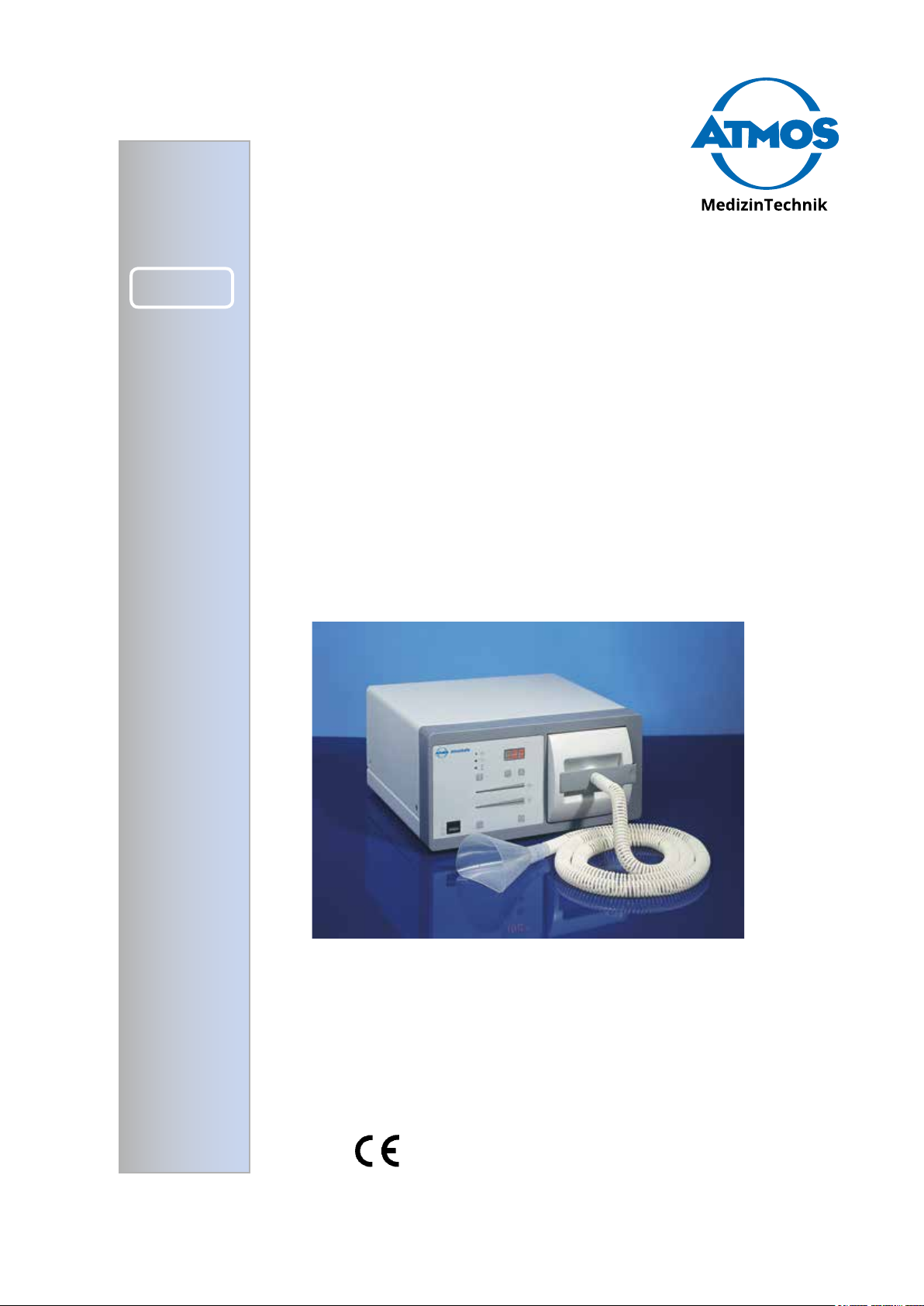
AtmoSafe
Operating Instructions
GA1GB.220101.0
2017-02 Index: 14
Page 2

Table of contents
1.0 Introduction
1.1 Notes on operating instructions ............................3
1.2 Function ................................................................3
1.3 Explanation of symbols .........................................3
2.0 For your safety ............................................... 4-5
3.0 Intended use ........................................................6
4.0 Setting up and starting up
4.1 Illustrations ........................................................ 7-9
5.0 Operation
5.1 Initial start-up ......................................................10
5.2 Assembly ............................................................10
5.2.1 Installation together with a surgical device .........10
5.2.2 Main lter ............................................................10
5.2.3 Hose ....................................................................10
5.2.4 Prelter ................................................................11
5.2.5 Check on supply voltage ..................................... 11
5.3 Settings ............................................................... 11
5.4 Display elements.................................................12
5.5 Aspiration ............................................................12
5.6 Options................................................................12
5.7 Service level.................................................. 13-14
6.0 Cleaning and care
6.1 General information on cleaning and disinfection 15
6.2 Reprocessing of hoses and secretion canister ...15
6.3 Cleaning and disinfecting the surface of the unit 15
7.0 Maintenance and Service .................................16
8.0 Troubleshooting ................................................17
9.0 Accessories and spare parts
9.1 Accessories .........................................................18
9.2 Spare parts .........................................................18
10.0 Technical data ...................................................19
11.0 Disposal .............................................................20
12.0 Notes on EMC .............................................. 21-23
ATMOS
MedizinTechnik GmbH & Co. KG
Ludwig-Kegel-Straße 16
79853 Lenzkirch
Germany
Phone +49 7653 / 689-0
Fax: +49 7653 / 689-190
+49 7653 / 689-493 (Service Center)
atmos@atmosmed.de
www.atmosmed.com
2
All rights regarding these operating instructions, in particular
the right of reproduction and dissemination, and that
of translation, are reserved. No part of these operating
instructions may be reproduced in any form (by photostat,
microlm, or other processes) without prior written
permission of ATMOS MedizinTechnik GmbH & Co. KG
or by using electronic systems processed, duplicated, or
disseminated. The information contained in these operating
instructions may be changed or amended without prior
announcement and does not represent any liability on the
part of ATMOS MedizinTechnik GmbH & Co. KG.
© ATMOS MedizinTechnik GmbH & Co. KG, 1999
Printed by: ATMOS MedizinTechnik GmbH & Co. KG
Page 3
1.0 Introduction
!
1.1 Notes on Operating Instructions
• These operating instructions contain important notes
on how to operate the ATMOSafe safely, correctly and
effectively. Therefore, they are intended not only for new
operating personnel to be instructed in its use, but also
for use as a reference manual. They help to avoid risks,
and also to reduce repair costs and down-times. Furthermore, reliability and service-life of the equipment will be
increased. For these reasons these operating instructions
must always be kept available near the device.
Prior to rst use please peruse the chapter 2.0 “For your
safety”.
The basic principles are:
Judicious and careful work provides best protection
against accidents!
Maintenance and repair work may be carried out only by
expert personnel authorised by ATMOS. In case of repairs
you should insist that only original spare parts are used. You
will then have the warranty that operational safety, readiness
for work and the value of your device will be preserved.
• The product ATMOafe bears CE marking CE according
to the EC Directive of the council for medical products
93/42/EEC and meets the basic requirements of Appendix I of the directive.
• The product ATMOSafe complies with all applicable
requirements of the Directive 2011/65/EC restricting the
use of certain hazardous substances in electrical and
electronic equipment (“RoHS”).
• The declaration of conformity and our general standard
terms and conditions can be obtained on our website at
www.atmosmed.com.
• The quality management system applied at ATMOS has
been certied according to international standards EN
ISO 13485.
• ATMOS will supply a service manual containing detailed
circuit descriptions and schematics as well as information on adjustment and servicing to service organizations
authorized by ATMOS.
• Reprints (also in extracts) only with permission in written
form by ATMOS.
Short cuts / symbols contained in these operating
instructions:
• Indicating a list
- Subdivision of a list/activity
The recommended sequence must be followed in each
case!
) Indicating particularly important advice!
ª Describing the effect of an activity
1.2 Function
• The AtmoSafe is an electrically operated medical device,
cleaning the air in medically used rooms from fume and
gas constituents arising from vaporising of human or
animal tissue. This fume arises typically when using laser
or electro-surgical devices and is consisting as a rule of
water vapour, aerosol, and organic gases.
• The AtmoSafe improves the environmental conditions in
the operating theatre:
- Reduction of the dust load by removing respirable
particles
- Improvement of view
- Removal of foul-smelling and partly toxic organic
gases
- Evacuation and ltering of hazardous bio-aerosol
(ltration of viruses)
• The AtmoSafe draws in the fume-laden air through a de-
vice positioned at the surgical application part or through
a separate hose, manually held near the application part.
By means of a high-efciency lter the drawn-in air is
cleaned of the hazardous matter and returned again into
the ambient air.
• Cleaning of the air refers to constituents like aerosol,
which is being retained by means of an ULPA high-efciency particle lter, as well as to organic gases, which,
amongst other characteristics, feature a smell unpleasant
for human beings, retained by a special gas lter.
1.3 Explanation of symbols
Caution, observe operating
instructions!
Equipment safety fuse Foot switch
Potential equalisation Filter Anaesthetic-tested
Application part type CF, de-
protected
Delayed stop period Stop Display: Filter to be changed
Base ow Operation ow Alternating current
Follow operating
instructions! (blue)
Start
Display: Air passage blocked
Unit must not be exposed to explosive
anaesthetic gases
Protected for use in explosive
atmospheres
3
Page 4
2.0 For your safety
2.0 For your safety
• The AtmoSafe has been designed in accordance with IEC 601/ EN 60601. The equipment con-
forms to VDE Safety Class I. It must only be connected to a properly installed earthed socket.
• Before connecting the device it needs to be checked whether the requested mains voltage of
the device matches the mains voltage of the mains power supply.
• The AtmoSafe may be used only by trained staff under supervision (IEC 601-1 / EN 60601-1).
• Following transportation at low temperatures (<0°C) the appliance must be held for up to six
hours at ambient temperature before rst start-up. If the AtmoSafe is not acclimatized, it may
not be used.
• The suction hose must never come into direct contact with the evacuation position in order to
avoid suction adherence on the tissue.
• Check device, power cable, accessories, connection cables and hoses for damage before
start-up. Defect cables and hoses must be replaced immediately. Check functions of the device
prior to using it!
• Disconnection from supply network only by pulling the mains plug! First the plug is to be pulled
from the wall socket. Then disconnect the connection line from the device.
• Never touch plug or line with wet hands.
• Please observe the ambient conditions stated in the technical data (chapter 10.0).
• Pay attention to maximum stability of the installation surface.
• The device must only be operated in rooms designated for medical use. The AtmoSafe is not
designed to be used in an explosion-hazardous environment. Explosion-hazardous areas
may be caused by the use of ammable anaesthetics, skin cleansing products and skin disinfectants. The suction opening of the hose should not lie on the oor Evacuation of explosive
endogenous gases (e.g. methane) from the intestinal tract is also prohibited.
• The foot switch must be suitable for use in areas subject to explosion hazards. Foot switches
used on operation theatres must have a watertight switching element (IPX 8).
• This product is not re-sterilizable. Repeated reuse of components which are marked with a
is forbidden. In case of repeated reuse these components lose their function and there is a
high infection risk.
• The AtmoSafe may be operated only in rooms used for medical purposes, but not in areas
subject to explosion hazards and in oxygen rich environments.
2
• Do not allow any liquid to get into the device or be sucked in. If liquids have penetrated the
device, it may not be operated again until it has been checked by the customer service centre.
• The AtmoSafe meets the immunity to interference requirements of IEC 601-1-2 / EN 60601-1-2
EMC
„Electromagnetic Compatibility – Medical Electrical Devices“.
4
Page 5
2.0 For your safety
• ATMOS is not liable for personal injury and damage to property if
- no original ATMOS parts are being used,
- the advice for use in these operating instructions is not being observed,
- assembly, new settings, alterations, extensions and repairs have been carried out by person-
nel not authorised by ATMOS.
Sterile
Hospital
Grade
• In the surgical invasive sterile area sterile parts only may be used. Hoses, application parts, as
well as instruments, must be used either as sterile single-use part or sterilised multiple-use part.
• Power cables must correspond to the applicable national regulations. The suitability for medical
applications must be ensured in particular.
• In case of leaks in the system the indication for suction adherence may fail.
• With very low power setting at the HF surgical device auto activation may possibly not function.
• In case of high electromagnetic and performance-related interference the sensitivity of
auto activation must be reduced.
• Please note: A medical insulating transformer with earth leakage monitor or any similar safety
system acc. to EN 60 601-1 is required, if several devices are connected over one common
power supply. The transformer must correspond to the power consumption of all the devices to be
connected.
5
Page 6

3.0 Intended use
Name: AtmoSafe
Main functions: Smoke extraction system for use in con-
junction with smoke or gas producing medical appliances,
like laser and high-frequency surgical appliances, cauter-
ises, oscillation saw, and methods like the removal of bone
cement in revision endoprosthetics.
Medical indications / application: For extraction and
ltering of evaporated burn-off products arising with thermal
medical operations by vaporisation of tissue.
For extraction and ltering of aerosols, emitted by
oscillation saws (e.g. in autopsy).
For extraction and ltering of vapours arising when two com-
ponent adhesives or cement mixtures are mixed and used
(e.g. in implant surgical work).
Specication of the main function: The AtmoSafe draws
in the fume-laden air through a device positioned at the surgical application part or through a separate hose, manually
held near the application part. By means of a high-efciency
lter the drawn-in air is cleaned of the hazardous matter and
returned again into the ambient air. Cleaning of the air refers
to constituents like aerosols, which is being retained by
means of an ULPA high-efciency particle lter.
Application organ: No specic application organ
Application time: Short-term use on the patient
(< 30 days).
Application site: The application site is the clinical, outpa-
tient as well as the practices area. The application of the
device may only be performed by medically trained and
introduced staff .
Contraindications: No application outside of the medical
sector. No suction of ammable, corrosive and explosive
substances.
The product is: X active □ not active
Sterility: Not necessary
Single-use product / reprocessing: The device and part of
the accessories are reusable. For information on reprocessing and disinfection, please see the operating instructions.
6
Page 7
4.0 Setting up and starting up
4.1 Illustrations
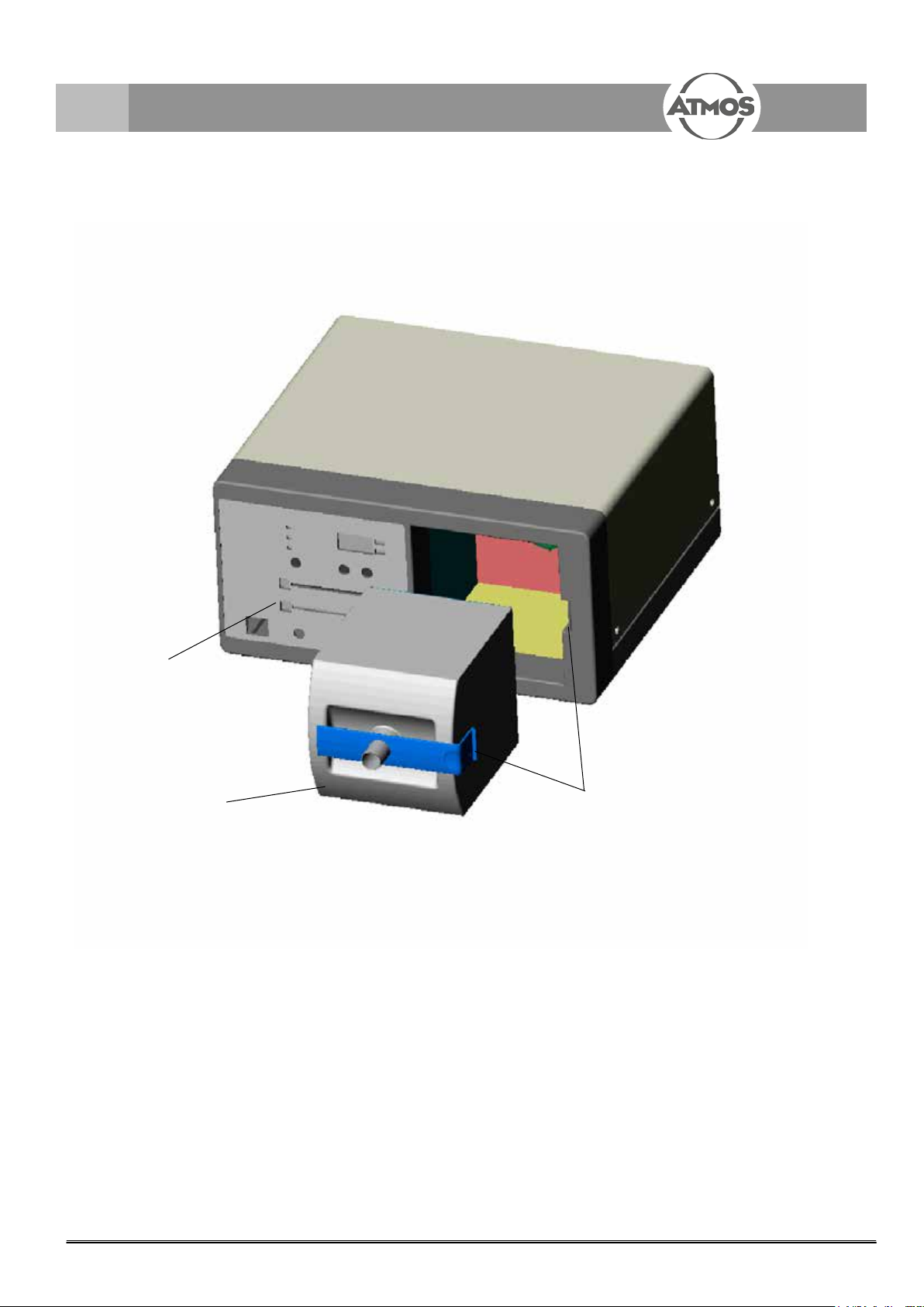
Fig. 1. AtmoSafe Overall view
Operator panel
Mains lter
Filter locking
7
Page 8
4.0 Setting up and starting up
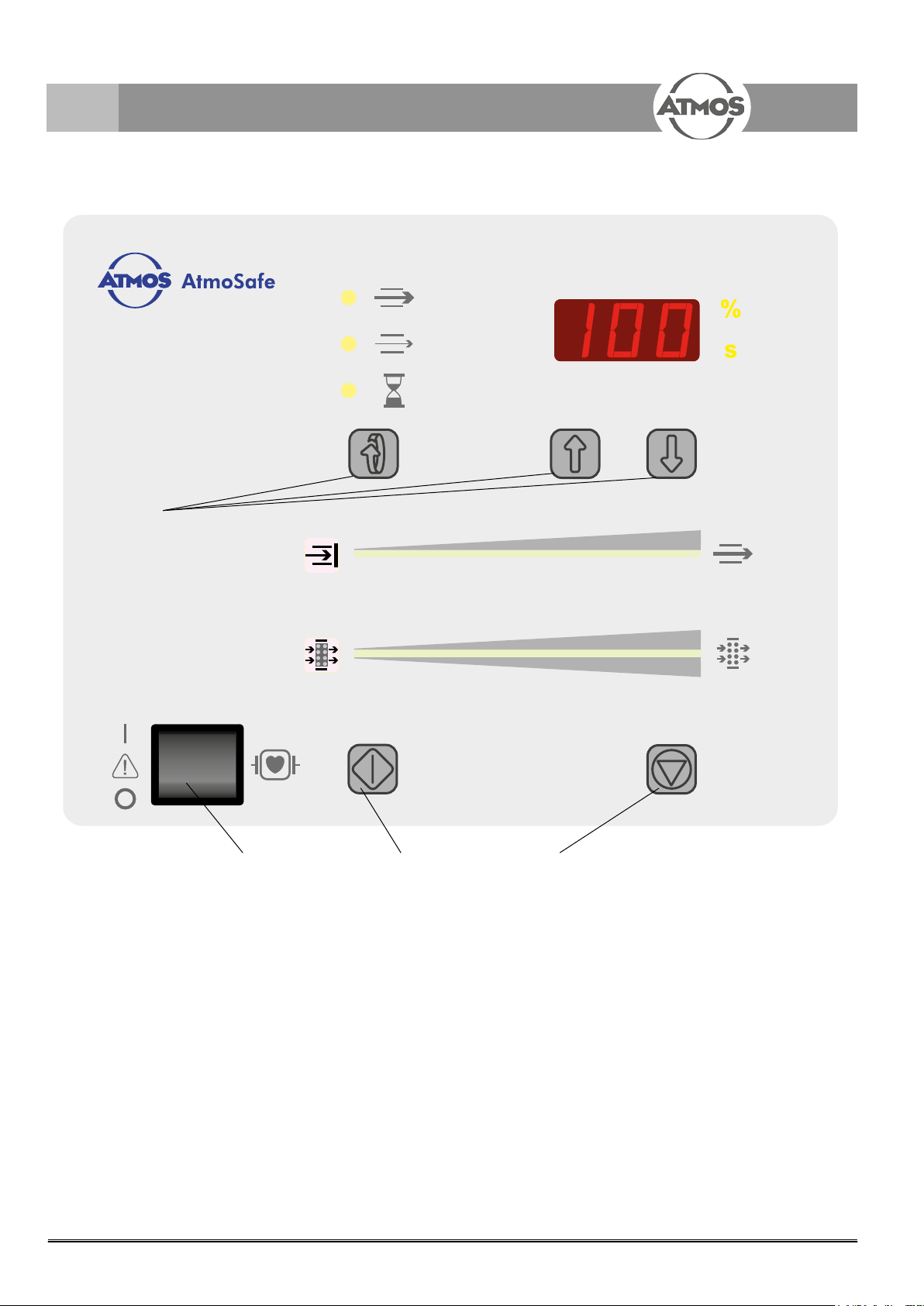
Fig. 2. Display and control elements
ON/OFF switch
Start button manual
Stop button manuel
Presetting buttons
Air ow display
Filter capacity display
8
Page 9

4.0 Setting up and starting up
Fig. 3. AtmoSafe Rear view
Mains supply
Equipment safety fuse
Non-heating apparatus mains connection for
an HF surgical device
Connection for potential equalization
Activation input
9
Page 10

5.0 Operation
5.1 Initial starting up
Prior to shipment each AtmoSafe is being inspected by the manufacturer for function and safety.
In order to make sure that the appliance is working safely after transport and installation, the
following points should be observed: The user should put the appliance into operation only if the
manufacturer or the supplier
Peruse safety information in part 2.0 prior to starting up the device for the rst time.
1. has carried out a functional test on the appliance at the place of operation
2. has instructed the person responsible for operating the device on how to handle the device
by means of the operating instructions.
6h
14
Following transportation at low temperatures (<0°C) the appliance must be held for up to six
hours at ambient temperature before rst start-up. When the device has not been acclimatised
evacuation cannot be activated The device is protecting itself.
5.2 Assembly
The device has to be positioned on a stable base; attention must be paid to the load carrying
capacity.
The base must not be soft (foamed material or similar), so that the exhaust air openings are not
covered.
5.2.1 Installation together with a surgical device
The power cable of the surgical device must be tted with an inlet connector for non-heating apparatus according to IEC 320.
This inlet connector for non-heating apparatus is plugged into the auxillary mains socket (, Fig.
3) on the rear of the AtmoSafe. The AtmoSafe is now controlling the power input of the surgical
device by means of the internal ISA device (Internal Synchronous Activation) and, in this way,
effects auto activation. Auto activation means that the evacuation mode is switched on as soon as
the thermal surgical function of the surgical device (Cut, coag,...) is activated.
Prior to rst use of the surgical device auto activation must be calibrated once. How the AtmoSafe
is to be adapted to the surgical device is said in Chapter 5.7.5 Calibration of auto activation.
10
Auto activation of the AtmoSafe works with most surgical devices in the power range 50 W...1400
W (for inst. ERBE ICC 350, ICC 50,...)
Only compatible devices may be connected to the auxiliary mains socket (,Fig. 3).
5.2.2 Main lter
• After having taken off the packaging and the plugs, please slide the main lter (, Fig. 1, p. 15)
into the lter shaft of the unit until it locks. Take care that the lter cover is on the right side.
When there is no main lter in the unit evacuation cannot be activated.
5.2.3 Hose
• After having taken off the packaging the hose (Ø 22 mm) is put with one end onto the connecting nipple of the main lter.
Page 11

5.0 Operation
Scroll
+
_
5.2.4 Prelter
• Please put the prelter onto the hose, preferably at the open hose end. The prelter protects
the hose and the main lter against coarse contamination. For more exibility at the hose end
near the eld of operation, the lter can be installed between the hose and the main lter. The
direction of ow must be taken care of, it is shown on the prelter. You must use only a clean
and dry lter.
5.2.5 Check on supply voltage
• Please check whether the mains voltage data shown on the fuse drawer (, Fig. 3, p. 17) of
the device agree with the values of the mains supply network, and then connect the AtmoSafe
to the supply network.
) If the AtmoSafe is used for surgical procedures, we recommend connecting it to the equipoten-
tial bonding connection of the room via connection.
The AtmoSafe is now ready for operation.
5.3 Settings
5.3.1 Presettings general
The values for operation ow, base ow, and delay can be set individually. By using the scroll button the desired parameter to be changed can be selected. The currently set ow value is shown
in the display in percent. The value can be set in % - related to the total rating of the device - by
1%-steps. The currently set delay is shown in the display in seconds. By means of the arrow buttons the value can be increased or reduced. With prolonged pressing of the corresponding arrow
button
5.3.2 Base ow
or , setting speed increases, so that also larger changes can be effected quickly.
Base ow
Operation ow
Delay
Also during interruptions of work, i.e. when there is no activation signal received from the laser or
the HF surgical device or from the foot switch received, the device works with reduced intensity. In
order to be able to set the ow intensity of this base ow you should activate the scroll button repeatedly until the indicating light next to the base ow symbol lights up. Now, you press the arrow
buttons until the desired value is obtained. This value can be set between 0 and 30 %. The base
ow is switched off after a certain period of time (work’s setting = 2 min). This time, i.e. the base
ow time, can be set on the service level. (See also chapter 5.7 Service level).
5.3.3 Operation ow
During the surgical operation, i.e. when there is an activation signal received from the laser or
from the HF surgical device or from the foot switch, the device shall extract the fumes which
develop with full intensity. In order to be able to set the ow rate of this operation ow you should
activate the scroll button repeatedly until the indicating light next to the operation ow symbol
lights up. Now, you press the arrow buttons until the desired value is obtained.
5.3.4 Delay
In order to prevent activation and de-activation of operation ow at short intervals during the frequent
interruptions between cutting and coagulation phases the ow continues for a certain period of time
after the end of the cutting / coagulation procedure (i.e. after the activation signal is off). In order to
be able to set the delay period of this operation ow you should activate the scroll button repeatedly until the indicating light next to the delay symbol lights up. Now, you press the arrow buttons
until the desired value is obtained. Adjustments from 0...100 sec are possible as well as “O ", i.e.
unlimited delay. With the adjustment “0 the start button or a connected foot switch has following
function (operated once = 'on', operated once again = 'off ').
11
Page 12

5.0 Operation
5.4 Display elements
5.4.1 Flow indication
This points out the air resistance arising in the air passage (through the hose and lter system).
When all the green bars are lit up, the suction resistance is low. The less bars are lit, the lower
the ow. The display permits to draw conclusions, for inst. regarding the degree of blocking of the
prelter.
When the system is completely blocked, all the green bar indicators are off, and the display on the
left lights up red.
5.4.2 Filter capacity
The display of lter capacity permits quick assessment of the current lter status. The more green
bar indicators are lit up, the more capacity there is still left. With full exhaustion of lter capacity
the green indicators are off, and the display on the left lights up red.
5.5 Aspiration
Flow
Filter
Please ensure that for invasive treatment the following parts are sterile with each new patient:
- Suction hose incl. suction jets or suction set.
- All parts extending into the operating eld, in particular those near or in contact with the
patient.
• Switch on the AtmoSafe by means of power switch (, Fig.2, p. 16).
• Please ensure that the suction hose is correctly positioned, i.e. that no sensitive parts or swabs
or similar, are sucked in.
• Please activate now the ow by pressing the start button or the connected foot switch. The
device will continue to work as long as the button is pressed. Thereafter, the ow will continue
for the duration of the set delay period (see Chapter 5.3.4).
5.6 Options
5.6.1 Foot switch (Art. No. see accessories)
• Explosion-protected switch (AP safety) for switching ow on and off.
- Connect the foot switch.
- When pressing the foot switch the ow is switched on. After releasing the foot button the
device will continue to work for the duration of the set delay period.
- The function of the foot button is the same as that of the start button.
12
Page 13

5.0 Operation
Scroll
Main switch
5.7 Service level
The service level permits the user to change certain ex work's settings.
You will reach the service level by pressing the SCROLL button (, Fig. 2, p. 16) and then switch-
ing on the device by means of the power switch (, Fig. 2, p.16). Then in the display will appear:
Basic program - Display "S 0 “
Button Description
Selection of service sub-program (plus)
Selection of service sub-program (minus)
Exit form service mode
Calling the corresponding sub-program
Sub-programs – overview
Display Description
S 0 Change brightness of display
S 1 Automatic activation on / off
S 2 Suction adherence indication on / off
S 3 Change base ow period
S 4 Calibration on auto activation (automatic)
S 5 Calibration on auto activation (manual)
5.7.1 S 0 Change brightness of display
Display: 0 0 ..... 010 (Brightness value)
Button Description
Brightness +
Brightness -
Return (incl. store)
Description:
Brightness can be set between 0 and 10.
5.7.2 S 1 Automatic activation on / off
Display: 1 0 (Activation off) 1 1 (Activation on)
Button Description
Activation on
Activation off
Return (incl. store)
Description:
The activation by means of the integrated current sensor can be switched on and off as required
13
Page 14

5.0 Operation
5.7.3 S 2 Suction adherence indication on / off
Display: 2 0 (Suction adherence indication off) 2 1 ((Suction adherence indication on)
Button Description
Suction adherence indication on
Suction adherence indication off
Return (incl. store)
Description:
The suction adherence indication can be switched on and off as required Suction adherence indication can be switched on and off as required.
5.7.4 S 3 Change base ow period
Display: 300 .... 399 (Base ow period in seconds)
Button Description
Base ow period +
Base ow period -
Return (incl. store)
Description:
Here the base ow period can be set. The device remains in base ow mode, as determined by
this setting. Thereafter the device is switched off. With setting 99 there is no time limit for the base
ow.
5.7.5 S 4 Calibration on auto activation (automatic)
Display: 499 .... 400 (Potentiometer setting in %)
Button Description
Start of calibration
Termination
Following auto-calibration manual postprocessing takes place automatically (see S 7).
Description:
Prior to starting auto-calibration the corresponding surgical device must be connected and activated. The set position should be the minimum setting. The device will then search automatically
for the corresponding setting value. For validation, automatic calibration is always followed by
manual calibration (see S 7).
5.7.6 S 5 Calibration on auto activation (manual)
Display: 500 .... 599 (Potentiometer setting in %) All LEDs (on = activation takes place, off =
no activation)
Button Description
Activation threshold + (less sensitive)
Activation threshold – (more sensitive)
Return (incl. store)
Description:
Here sensitivity of automatic activation can be set. For doing this, the corresponding HF device
must be connected. The setting must be done in a manner that with activated surgical device the
LEDs are lit, and with non-activated surgical device the LEDs are not lit.
14
Page 15

6.0 Cleaning and care
6.1 General information on cleaning and
disinfection
• For disinfection, you may use all surface and instrument
disinfectants listed on page 32.
) There are disinfectants which can cause discolouration of
plastic parts, like the lter case, etc.; this however does
not effect the function of the parts.
) Always observe the concentration specications and
instructions by the respective manufacturer!
6.2 Reprocessing of the hoses
) Please ensure that the following parts have been disin-
fected before treating a new patient:
- Suction hose incl. suction jets or suction set.
• Washing and disinfecting in an automatic cleaner and
disinfector is also possible.
Thermal disinfection is carried out at 93° C.
• After disinfecting the parts are to be mounted again
(Chapter 5.0 “Operation”).
Recommended instrument disinfectants
Disinfectant Producer
GIGASEPT FF Schülke & Mayr, Norderstedt
Sekusept PLUS Henkel, Düsseldorf
Mucozit-T Merz & Co., Frankfurt/Main
Recommended surface disinfectants
Disinfectant Producer
TERRALIN Schülke & Mayr, Norderstedt
QUATOHEX Braun, Melsungen
Incidin Plus Henkel, Düsseldorf
Pursept-A Merz & Co., Frankfurt/M.
(Disinfection spray
or disinfection cloth)
6.3 Cleaning and disinfecting the
surface of the unit
) You must disconnect the mains plug before cleaning and
disinfecting the unit casing.
) Wipe-disinfection:
Wipe the unit surface with a cloth moistened with a
cleaning or disinfecting solution. Do not allow any liquid
to get into the device. The cleaning agents and disinfectants listed in the next section are all suitable.
) If liquid has penetrated the unit, it may not be operated
again until it has been checked by the authorised customer service centre.
) Do not use disinfectants containing alcohol.
15
Page 16

7.0 Maintenance and Service
The base device is maintenance-free.
Filter replacement:
• As described in operating instructions, section 5.2.2 Main
lter.
Preventive maintenance of evacuation
system:
• Prior to every use a visual inspection of the device,
hoses, main and prelter and mains power cable must be
performed.
When using further accessories, like liquid vessel, foot
switch or activation sensors, also these should be subjected to a visual check.
• Replace any damaged parts immediately.
• The unit does not require any further maintenance.
Corrective maintenance of system:
• Any changes or repairs may - with due regard to the
special requirements for medical products - be carried
out only by the manufacturer or by persons expressly
authorised by the latter.
• Please comply with the country-specic guidelines re-
garding regular testing especially for the electrical safety.
ATMOS recommends a test every 24 months.
Sending in the device
1. Remove and properly dispose of consumables.
2. Clean and disinfect the product and accessories according to the operating instructions.
3. Place used accessories with the product.
4. Fill in the form QD 434 „Delivery complaint / return shipment“ and the respective decontamination certicate.
• This form is enclosed to each delivery and can be found
at www.atmosmed.com.
5. The device must be well padded and packed in suitable
packaging.
6. Place the form QD 434 „Delivery complaint / return shipment“ and the respective decontamination certicate in
an envelope.
7. Afx the envelope to the outside of the package.
8. Send the product to ATMOS or to your dealer.
16
Page 17

8.0 Troubleshooting
Abhilfe
– Netzstecker sitzt schlecht
– keine Netzspannung
– Sicherung defekt
– Anschluß an Steckdose überprüfen
– Haussicherung überprüfe n
– Sicherung vom Service austauschen lassen
– Und ichte S tellen in Schlauc hlei t ung e n
– Hauptfilter ist verblockt
– Vorfilter ist verblockt
– Schlauchleitungen auf festen Sitz überprüfen
– Hauptfilter wechseln
– Vorfilte r wechseln
– Kalibrierfehle r des interne n
– K und endi e nst muß die K alib ri e rung vor O rt durchfüh re n
Abhilfe
– Netzstecker sitzt schlecht
– keine Netzspannung
– Sicherung defekt
– Anschluß an Steckdose überprüfen
– Haussicherung überprüfe n
– Sicherung vom Service austauschen lassen
– Und ichte S tellen in Schlauc hlei t ung e n
– Hauptfilter ist verblockt
– Vorfilter ist verblockt
– Schlauchleitungen auf festen Sitz überprüfen
– Hauptfilter wechseln
– Vorfilte r wechseln
– Kalibrierfehle r des interne n
Drucksensors
– K und endi e nst muß die K alib ri e rung vor O rt durchfüh re n
– Üb ertemperatur (>69°C) oder
– Gerät ausschalten und warten bis die Temperatur im Geräte-
Abhilfe
– Netzstecker sitzt schlecht
– keine Netzspannung
– Sicherung defekt
– Anschluß an Steckdose überprüfen
– Haussicherung überprüfe n
– Sicherung vom Service austauschen lassen
– Und ichte S tellen in Schlauc hlei t ung e n
– Hauptfilter ist verblockt
– Vorfilter ist verblockt
– Schlauchleitungen auf festen Sitz überprüfen
– Hauptfilter wechseln
– Vorfilte r wechseln
– Kalibrierfehle r des interne n
Drucksensors
– K und endi e nst muß die K alib ri e rung vor O rt durchfüh re n
– Üb ertemperatur (>69°C) oder
Untertemperatur (<0°C)
– Gerät ausschalten und warten bis die Temperatur im Geräte-
inneren sich wieder normalisiert hat.
– Datenfehler auf der Hauptplatine – Gerät aus- und wiedereinschalten. Sollte jetzt die Festsaug-
erkennung nicht mehr funktionieren, muß der Kundendienst vor
Ort eine K a lib rier ung vor ne hme n.
– Gebläse ohne Lei stung – Gerät aus- und wiedereinschalten. Bei erneutem Fehler Kunden-
The AtmoSafe was subjected to a thorough quality control in the factory. If however any problems should occur, you can possibly eliminate these personally, if observing the following notes.
Error indication Possible cause Remedy
• Device does not start - Power plug is tted badly - Check connection at wall socket
- No mains voltage - Check main fuse
- Defect fuse - Have fuse replaced by service
• Insufcient ow - Leaks in hose lines - Check hose lines for rm seating
- Main lter is blocked - Replace main lter
- Prelter is blocked - Replace prelter
• Display
• Display
- Calibration defect of intern pressure sensor
- Excess temperature (>69°C) or
sub temperature (<0°C)
- Service must carry out calibration on site
- Switch off device and wait until
temperature inside the device
returns to normal
• Display
• Display
- Data fault on main board - Switch device off and on again.
Should now suction adherence indication no longer work,
customer service must carry out
calibration on site.
- Blower does not work - Switch device off and on again.
With renewed defect inform
service.
17
Page 18

9.0 Accessories and spare parts
9.1 Accessories
Operating instructions ........................... GA1GB.220101.0
Connection line for electric equipotential bonding
(possibly only in operating theatre) .................. 008.0596.0
Foot switch for AtmoSafe, suitable for
use in Zone M (not for operating theatre),
explosion-protected, IPX 1 ............................... 445.0061.0
OP foot switch for AtmoSafe, suitable for use in
Zone M, explosion-protected, IPX 8 .................445.0068.0
Standard rail set 25 x 10 mm / 315 mm for lateral
mounting to AtmoSafe .....................................445.0064.0
Hose holder for insertion into standard rails
(25 x 10 mm or 30 x 10 mm), for air hoses with
Ø 22 mm ..........................................................445.0066.0
Surgical handle, with integrated suction chan-
nel, with standard international plug-connection
HF surgical devices, incl. air hose 10 mm, 2.5 m,
ESU cable length 3 m .....................................445.0062.0
Fume evacuation handle of clip-on type, for adap-
tion of mono-polar standard surgical handle, incl.
air hose Ø 10 mm and length 2.5 m .................445.0063.0
9.2 Spare parts
AtmoSafe compl. base package .....................445.0000.0
Air hose, Ø 22 mm (W), 2.10 m, for single-use, of
E.V.A. ............................................................... 005.0200.0
Air hose Ø 22 mm, L = 2.70 m made of
Hytrel, connecting sockets made of silicone
temperature-resistant up to 200 °C .................. 005.0201.0
Air hose Ø 22 mm, L = 2.10 m temperature-resist-
ant up to 200 °C ............................................... 005.0203.0
Air hose, internal Ø = 10 mm, L = 1.8
m, temperature-resistant up to 200 °C, made of
hytrel, connecting sockets made of silicone .....005.0204.0
Connection hose straight,
Ø 22 mm (M) to Ø 22 mm (M) .......................... 000.0683.0
Connection hose straight,
Ø 22 mm (M) to Ø 10 mm (M) .......................... 000.0689.0
Connection hose straight,
Ø 22 mm (F) to Ø 10 mm (M) ..........................000.0688.0
Funnel, at on one side, of PP, with connection in
Ø 22 mm (F) .................................................... 000.0687.0
Suction tube, plastic, with ISO cone 22 mm (M) for
suction hose Ø 22 mm (F) ...............................445.0055.0
Air hose Ø 10 mm, of various lengths .............. On request
Articulated arm with 3 joints for attaching to normal standard rails (25 x 10 mm),
extended length approx. 1.3 m, with 5 hose hold-
ers for hose with Ø 22 mm ............................... 445.0060.0
18
Prelter, in-line, (HEPA), with ISO connections in
Ø 22 mm (M/F) ................................................. 445.0044.0
Main lter unit for AtmoSafe,
multi-stage gas lter + ULPA particle lter,
micro-biocidal-coated compatible with the envi-
ronment ............................................................ 445.0040.0
Page 19

10.0 Technical data
Mains voltage (incl. tolerance) AtmoSafe WORLD: 100...230VAC ± 10% (total range 90...253VAC) can be
arranged by user / installer by inserting the correct fuse drawer
AtmoSafe EUROPE: 230 V ± 10 %
Mains frequencies (incl. tolerance) 50...60 Hz +/-1%
Mains supply Device inlet connector for non-heating apparatus
Auxiliary-mains power socket (IEC 320) 120 V / 9.7 A - 230 V / 6.3 A
Power consumption Max. 400 W
Blower air ow (free-ow) 1600 l/min
Device air ow 650 l/min electronically controlled
Activation Automatic activation, front-panel button, signal at activation input, optionally by
foot switch
Operation mode Suitable for continuous operation
Protective measures (Fuses,...) The power pack is tted with fusible cutouts 5 x 20. The motor of the blower is
thermally protected.
Fuse (Breaking capacity H) 100 V: T4A (125 V) / 120 V: T4A (125 V) / 230V: 3.15A (250 V)
Acclimatisation rules (Prior to start-up): 6 h acclimatisation after transport at low temperature
Maintenance The base device is maintenance-free. Filter change and change of single-use
articles (by user).
Designed freedom from maintenance >10 Years (20,000h) (blower, bearings, rubber parts, etc.)
Corrective maintenance (Acc. to DIN 31051 Measures for restoring the desired condition): Corrective
maintenance by ATMOS or by customer service authorised by ATMOS in
accordance with the country-specic regulations (in Germany DIN VDE 0751).
Period tests Recommended: Testing every 24 months.
Ambient conditions (In operation and in transport / storage):
Ambient temperatures In operation: +10 ... +40°C / in transport and storage: - 40 ... +70°C
Air humidity 5...95 % (without condensation)
Air pressure + 700...1060 hPa
Weight 14 kg
Dimensions (H x W x D) H 210 mm x W 368 mm x D 410 mm
Noise level Max. 52 dB(A)@1 m (as per ISO 7779)
Interfaces (Input and output) suction hose connection 7/8”(22 mm), equipotential bonding,
activation input, mains connection
Protection class I
MPG Class Class I
Applied part
Mains lter ULPA, retention = 99.9999 % @ 0.01μm
CF
debrillator-protected
19
Page 20

11.0 Disposal
Disposal of base device:
• Packaging consisting of cardboard and foamed polystyrene can be fully recycled or returned to your supplier.
• The AtmoSafe does not contain any hazardous materials.
• The housing is recyclable.
• The components of the product can be disposed like
normal electronic scrap Recyclable materials should be,
as far as possible and reasonable, delivered separately
to a recycling organisation.
Disposal of accessories:
• The main lter and other accessories are biologically
contaminated material and have to be disposed of by
specialist rms in compliance with given regulation.
20
Page 21

12.0 Notes on EMC
• Medical electrical equipment is subject to special precautions with regard to EMC and must be installed acc. to following EMC
notes.
• Portable and mobile HF communication facilities can inuence medical electrical equipment.
• The use of other accessories, other converters and cables than stated may lead to an increased emission or a reduced inter-
ference immunity of the equipment or system.
12.1 Guidelines and Manufacturer's Declaration - Emissions
The AtmoSafe is intended for use in the electromagnetic environment specied below. The customer or user of the AtmoSafe
should ensure that it is used in such an environment.
Emissions Test Compliance Electromagnetic Environment - Guidance
RF Emissions acc.to CISPR 11 Group 1 The AtmoSafe uses RF energy only for its internal
function. Therefore, its RF emissions are very
low and are not likely to cause any interference in
nearby electronic equipment.
RF Emissions acc. to CISPR 11 Class B
Harmonic emissions according to IEC
61000-3-2
Voltage uctuations/icker according to
IEC 61000-3-3
Class A
Corresponds
The AtmoSafe is suitable for use in all establishments, including domestic, and those directly
connected to the public low-voltage power supply
network that supplies buildings used for domestic
purposes.
The device may not be used directly next to other devices or piled up with other devices. If operation next to or piled with
other devices is necessary, please watch the device to check its intended operation in this arrangement.
11.2 Guidelines and Manufacturer's Declaration - Immunity
The AtmoSafe is intended for use in the electromagnetic environment specied below. The customer or user of the device
should ensure that it is used in such an environment.
Immunity Test IEC 60601- Test Level
Electrostatic discharge
(ESD) according to IEC
61000-4-2
Fast electrical transient/
burst IEC 61000-4-4
Surges IEC 61000-4-5 1 kV
Magnetic eld at power
frequency 50/60 Hz acc.
to IEC 61000-4-8
± 6 kV Contact
± 8 kV Air
± 2 kV Mains
± 1 kV I/Os
Differential
1 kV
Common
3 A/m 3 A/m Power frequency magnetic elds should
Compliance
Level
± 6 kV Contact
± 8 kV Air
± 2 kV Mains
Inapplicable
2 kV
Differential
1 kV
Common
Electromagnetic Environment - Guidance
Floors should be wood, concrete, or ceramic
tile. If oors are synthetic, the relative
humidity should be at least 30 %.
Mains power quality should be that of a
typical commercial or hospital environment.
Mains power quality should be that of a
typical commercial or hospital environment.
be that of a typical commercial or hospital
environment.
21
Page 22

12.0 Notes on EMC
Immunity Test IEC 60601- Test Level Compliance Level Electromagnetic Environment - Guid-
ance
Voltage Dips / Dropout
IEC 61000-4-11
< 5 % UT
(> 95 % Dip of the U
For 0.5 cycles
40 % U
T
(60% Dip of the UT)
For 5 cycles
< 5 % U
)
T
(> 95 % Dip of the U
For 0.5 cycles
T
Mains power quality should be that of a
typical commercial or hospital environment. If
)
T
the user of the AtmoSafe demands continued
function even in case of interruptions of the
energy supply, it is recommended to supply
40 % U
T
(60% Dip of the UT)
the Atmosafe from an uninterruptible current
supply or a battery.
For 5 cycles
NOTE U
70% U
T
(30 % Dip of the UT)
For 25 cycles
< 5 % U
(>95 % Dip of the U
T
T
For 5 sec
is the mains alternating current prior to application of the test levels.
T
70% U
(30 % Dip of the UT)
For 25 cycles
< 5 % U
)
(>95 % Dip of the U
For 5 sec
T
T
)
T
12.3 Guidelines and Manufacturer's Declaration - Immunity
The AtmoSafe is intended for use in the electromagnetic environment specied below. The customer or user of the device
should ensure that it is used in such an environment.
Immunity Test
Conducted RF IEC
61000-4-6
Radiated
HF disturbances
according to IEC
61000-4-3
IEC 60601- Test
Level
3 V
eff
150 kHz to 80 MHz
3 V/m
80 MHz to 2.5 GHz
Compliance Level Electromagnetic Environment - Guidance
3 V
eff
3 V/m
Portable and mobile communications equipment should
be separated from the AtmoSafe incl. the cables by no
less than the distances calculated/listed below.
Recommended distances:
d = (3.5 / V1) * √(P)
d = (3.5 / E1) * √(P) 80-800 MHz
d = (7 / E1) * √(P) 0.8-2.5 GHz
22
where „P“ is the max. power in watts (W) and d is the
recommended separation distance in meters (m).
Field strengths from xed transmitters, as determined by
an electromagnetic site (a) survey, should be less than
the compliance level (b).
Interference may occur in the vicinity of equipment
containing following symbol:
Page 23

12.0 Notes on EMC
NOTE 1 By 80 MHz and 800 MHz the higher frequency range applies.
NOTE 2 These guidelines might not be applicable in all cases. The emanation of electromagnetic waves is affected by ab-
sorption and reection of buildings, objects and people.
a The eld strength of stationary transmitters, such as base stations of cellular phones and mobile terrain radio
equipment, amateur radio transmitters, cbm broadcast and TV stations cannot be predestined exactly. To determine
the electromagnetic environment in regard to stationary transmitters, a study of the location is to be considered. If the
measured eld strength at the location where the AtmoSafe is used exceeds the above compliance level, the AtmoSafe is
to be observed to verify the intended use. If abnormal performance characteristics are noted, additional measures might
be necessary, e. g. a changed arrangement or another location for the device.
b Over the frequency range of 150 kHz to 80 MHz, eld strengths should be lower than 3 V/m.
12.4 Recommended safety distance between portable and mobile
RF Communications equipment and the AtmoSafe
The AtmoSafe is intended for use in electromagnetic environment in which radiated disturbances are controlled. The customer
or user of the AtmoSafe can help prevent electromagnetic interference by maintaining a minimum distance between portable
and mobile RF Communications equipment and the AtmoSafe as recommended below, according to the maximum output power
of the communications equipment.
Safety distance, depending on transmit-frequency m
Nominal output of the trans-
mitter
W
0.01 0.12 0.12 0.24
0.1 0.37 0.37 0.74
1 1.2 1.2 2.4
10 3.69 3.69 7.38
100 11.66 11.66 23.32
For transmitters for which the maximum nominal output is not indicated in the above table, the recommended safety distance
d in meters (m) can be determined using the equation belonging to the respective column whereas P is the maximum nominal
output of the transmitter in watts (W) acc. to manufacturer´s specication.
NOTE 1 By 80 MHz and 800 MHz the higher frequency range applies.
NOTE 2 These guidelines might not be applicable in all cases. The emanation of electromagnetic waves is affected by ab-
sorption and reection of buildings, objects and people.
150 kHz to 80 MHz
d = [ 3.5 / 3] √P
80 MHz to 800 MHz
d = [ 3.5 / 3] √P
800 MHz to 2.5 GHz
d = [ 7.0 / 3] √P
23
Page 24

ATMOS MedizinTechnik GmbH & Co. KG
Ludwig-Kegel-Straße 16
79853 Lenzkirch / Germany
Phone: +49 7653 689-0
atmos@atmosmed.de
www.atmosmed.com
 Loading...