

Page 1

Gebrauchsanweisung
ATMOS Aqua clean
Water Supply System
530.2120.B
502.1200.B
2014-08 Index: 07
Operating instructions
English
Page 2

2
ATMOS
Phone + 49 7653 689-0
Fax
+ 49 7653 689-392 (Sales Germany)
+ 49 7653 689-391 (Export)
E-Mail: atmos@atmosmed.de
www.atmosmed.de
MedizinTechnik GmbH & Co. KG
Ludwig-Kegel-Str. 16
79853 Lenzkirch
Germany
Further information, accessories, consumables and
spare parts are available from:
Table of Contents
1.0 Introduction ............................................................... 3-6
1.1 Notes on operating instructions ...................................... 3
1.2 Intended use .................................................................. 3
1.3 Function ......................................................................... 4
1.4 Scope of supply .............................................................. 5
1.5 Transport and storage ................................................... 5
1.6 Explanation of pictures and symbols .............................. 6
2.0 For your Safety ............................................................. 7
3.0 Setting up and starting ........................................... 8-11
3.1 Installation in the auxiliary housing ................................ 8
3.2 Hose connections .......................................................... 8
3.2.1 Initial connection of the chemical bottle ........................ 8
3.3 Explanation of the controls ............................................. 9
3.4 Connection conditions for ATMOS S 61 Servant ......... 10
3.5 Connection conditions for irrigation and stimulation
devices ..........................................................................11
4.0 Cleaning and disinfection ......................................... 12
4.1 Disinfectant / Changing the chemical bottle ................. 12
4.1.1 Disinfectant .................................................................. 12
4.2 Care and cleaning ........................................................ 13
5.0 Maintenance .............................................................. 14
5.1 Regular checks ............................................................ 14
6.0 Retrofi tting ............................................................. 15-26
6.1 Retrofi tting at ATMOS S 61 Servant ........................ 15-20
6.1.1 Tubing .......................................................................... 17
6.1.2 Retrofi tting of a delay PCB ........................................... 18
6.1.3 Delayed switching circuit for Aquastop ......................... 19
6.1.4 Water connections ....................................................... 20
6.2 Retrofi tting at ATMOS Servant 5 / 5 C..................... 21-26
6.2.1 Drilling .......................................................................... 21
6.2.2 Tubing .......................................................................... 22
6.2.3 Add-on kit ..................................................................... 22
6.2.4 Delayed switching circuit for Aquastop until 2005 ........ 23
6.2.4.1 Delayed switching circuit for Aquastop from 2006 ....... 24
6.2.5 Water connections until 2005 ....................................... 25
6.2.5.1 Water connections from 2006 ...................................... 26
7.0 Troubleshooting ......................................................... 27
8.0 Accessories and spare parts .................................... 27
9.0 Technical information ........................................... 28-29
9.1 Structure ....................................................................... 28
9.2 Electrical connections, control PCB ............................. 29
9.3 Wiring diagram ............................................................. 29
10.0 Technical specifi cations ............................................ 30
11.0 Disposal ...................................................................... 31
12.0 Notes on EMC ........................................................ 32-34
ATMOS General Terms and Conditions
Page 3
3
1.0 Introduction
1.1 Notes on operating instructions
● The product ATMOS Aqua clean bears CE marking according to the EC Directive of
the council for medical products 93/42/EEC and meets the essential requirements
of Appendix I of the Directive.
● The product ATMOS Aqua clean complies with all applicable requirements of the directive
2011/65/EC restricting the use of certain hazardous substances in electrical and electronic
equipment (“RoHS”).
● The declaration of conformity can be obtained on our website at www.atmosmed.com.
● The quality management system applied at ATMOS has been certified according to
international standards EN ISO 9001 and EN ISO 13485.
● The product ATMOS Aqua clean fulfils the EN 1717 by the integrated free flow outlet.
● Prior to start-up please peruse chapter 2.0 „For your safety“, in order to be prepared for any
possible dangerous situations.
● These operating instructions are based on the version of the ATMOS Aqua clean available at the
print date. The same applies to the applied safety-related standards.
●
Subject to alterations, errors excepted.
1.2 Intended use
These operating instructions contain important notes on how to operate the ATMOS Aqua clean safely, correctly and effectively. Their reading helps to avoid risks, and also to reduce repair costs and
down-time. That increases, amongst other things, the reliability and service-life of the device.
These operating instructions serve not only for new operating personnel to be instructed in its use,
but also for use as a reference manual. Reproduction of these instructions – even in part – only with
the written permission of ATMOS.
These operating instructions must always be kept available near the device.
Care and safety inspections in conjunction with professional execution provide for operational safety
and readiness for use of your ATMOS Aqua clean and are therefore a must besides regular
cleaning.
Repair work and safety inspections may be carried out only by expert personnel authorised by
ATMOS. By applying only original spare parts you will have the guarantee that operational safety,
readiness for work and the value of your ATMOS Aqua clean will be preserved.
Name: ATMOS® Aqua Clean
Main functions:
Device for water separation and decontamination system for
hoses used in ENT treatment units and diagnostic devices.
Med. indications/ application:
Ear irrigation, thermal nystagmus stimulation
Specifi cation of the main function:
• The ATMOS Aqua Clean separates decontaminated water
from the fresh water by the integrated free fl ow outlet.
• The decontamination of water and hoses is enabled by the
use of a special disinfectant (ATMOS Green & Clean WK).
Application organ:
Mouth to pharynx, auditory canal to the ear drum and the
nasal cavities
Application time:
Temporary application (less than 60 minutes)
Application site:
Application sites are clinics and practices for ENT doctors
and phoniatrists. The examination with the water separation
and decontamination system may only be executed by medically trained persons.
Contraindications: No
The product is: X active □ not active
Sterility:
The water separation and decontamination system is not a
sterile product.
Single use product / reprocessing:
The device and part of the accessories are reusable. For
information on reprocessing and disinfection please see the
operating instructions.
Page 4
4
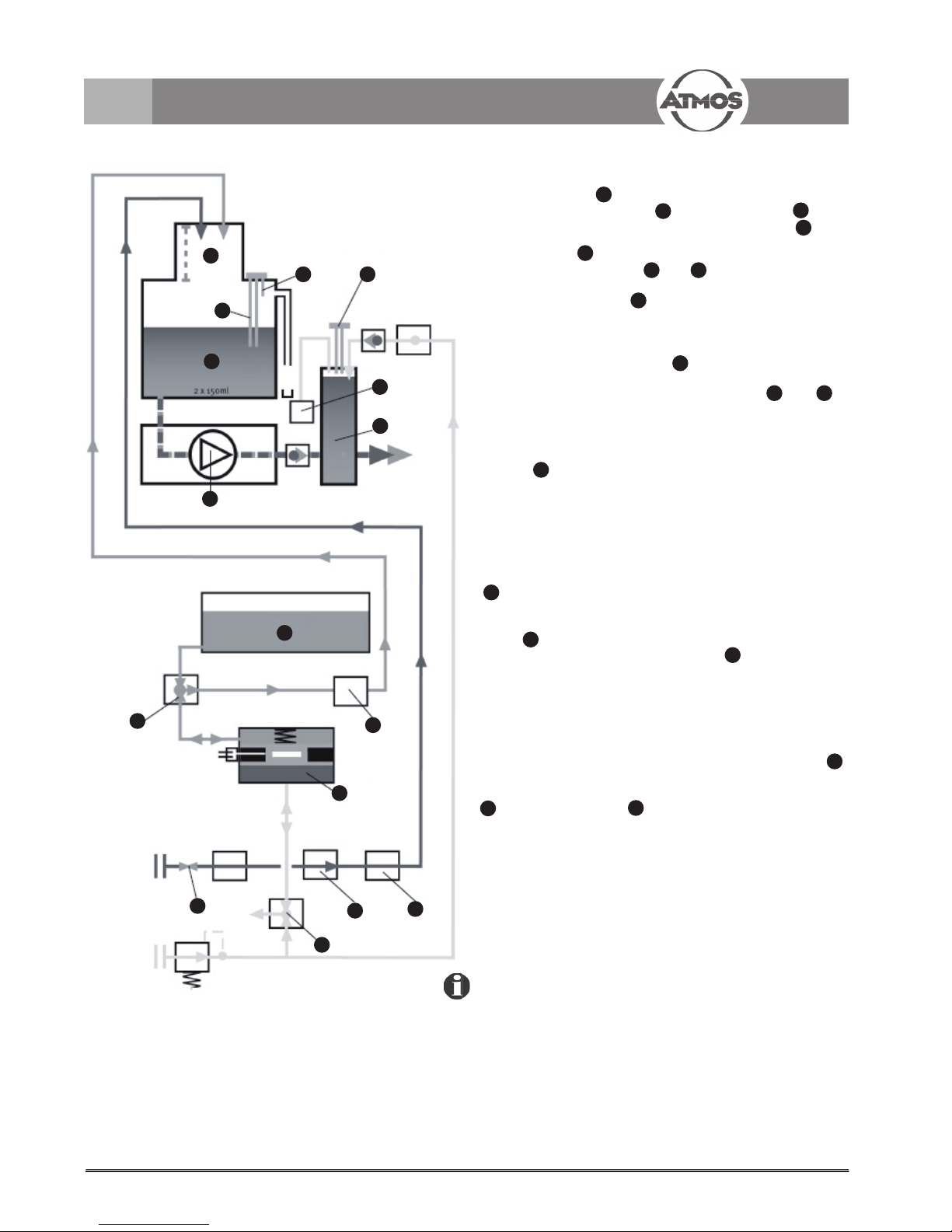
1.3 Function
When the water tap is opened and the system is
switched on, the dosing valve and the safety valve open
and 150 ml water are supplied to the mixing container .
The water level in the mixing container is monitored by an
electronic probe . Once the contact on the probe is
set off, the magnetic valves and (compressed
air/chemical) open. This activates the compressed air driven
double-membrane pump , causing 1.75 ml hydrogen
peroxide to be withdrawn from the chemical bottle and
added to the mixing container.
If the water level drops below probe A, the dosing valve
opens again until overfl ow probe is reached. By the
time the water reaches this probe, the mixing container has
been fi lled with 300 ml of water. Magnetic valves and
open again, and add another 1.75 ml of chemical to the mixing
container. This ensures that the required concentration of
disinfectant in the solution is continuously maintained.
In the mixing container, the water inlet is in the form of a
cascade , ensuring that the ATMOS Aqua clean is
separated from the water supply, as required by the DVGW
(The German Gas and Water Association) (DIN 1988, Part 4).
This ensures that water contaminated with micro-organisms
or mixed with chemicals cannot fl ow back into the water
supply system.
If a water-fed unit is activated, the decontaminated water
fl ows from the mixing container, via the pressure container
and to the appropriate instrument.
Naturally, this causes the water level in the pressure container
to fall, together with the water pressure. A pressure-sensitive
switch , fi tted to the pressure container and adjusted
to 3.5 bar, activates the membrane pump , which is
responsible for emptying the mixing container, fi lling the
pressure container and maintaining the required water fl ow
pressure.
An air cushion in the pressure container compensates the
water level. If necessary, the air cushion is topped up with
compressed air (magnetic valve 4) - all this is done to ensure
a stable water jet for the instrument. The air cushion probe
ensures that the air pressure is kept constant.
The disinfectant is withdrawn from the chemical bottle
. A disinfectant sensor controls the chemical
existence. If no more chemical can be withdrawn (e.g. the
chemical bottle is empty), an error message occurs.
Please note that only ATMOS Green&Clean WK
may be used, as the electrical sensors are adjusted
to this product!
1.0 Introduction
10
5
9
14
12
11
13
4
6
15
16
1
2
3
7
8
1
2
3
4
6
7
8
9
10
11
12
13
14
15
16
Fig. 1
5
6
7
Page 5
5
1.0 Introduction
1.4 Scope of supply
Prior to dispatch, this ATMOS Aqua clean was subjected to
an extensive functional test and has been carefully
packed.
Nevertheless, please compare the contents of the shipment
on completeness immediately upon receipt (see delivery
note).
● ATMOS Aqua clean
● bottle support
● 1 l ATMOS Green & Clean WK
● connecting kit
1.5 Transport and storage
● The transport of the device may be effected only in a
dispatch carton upholstered and offering suffi cient pro-
tection.
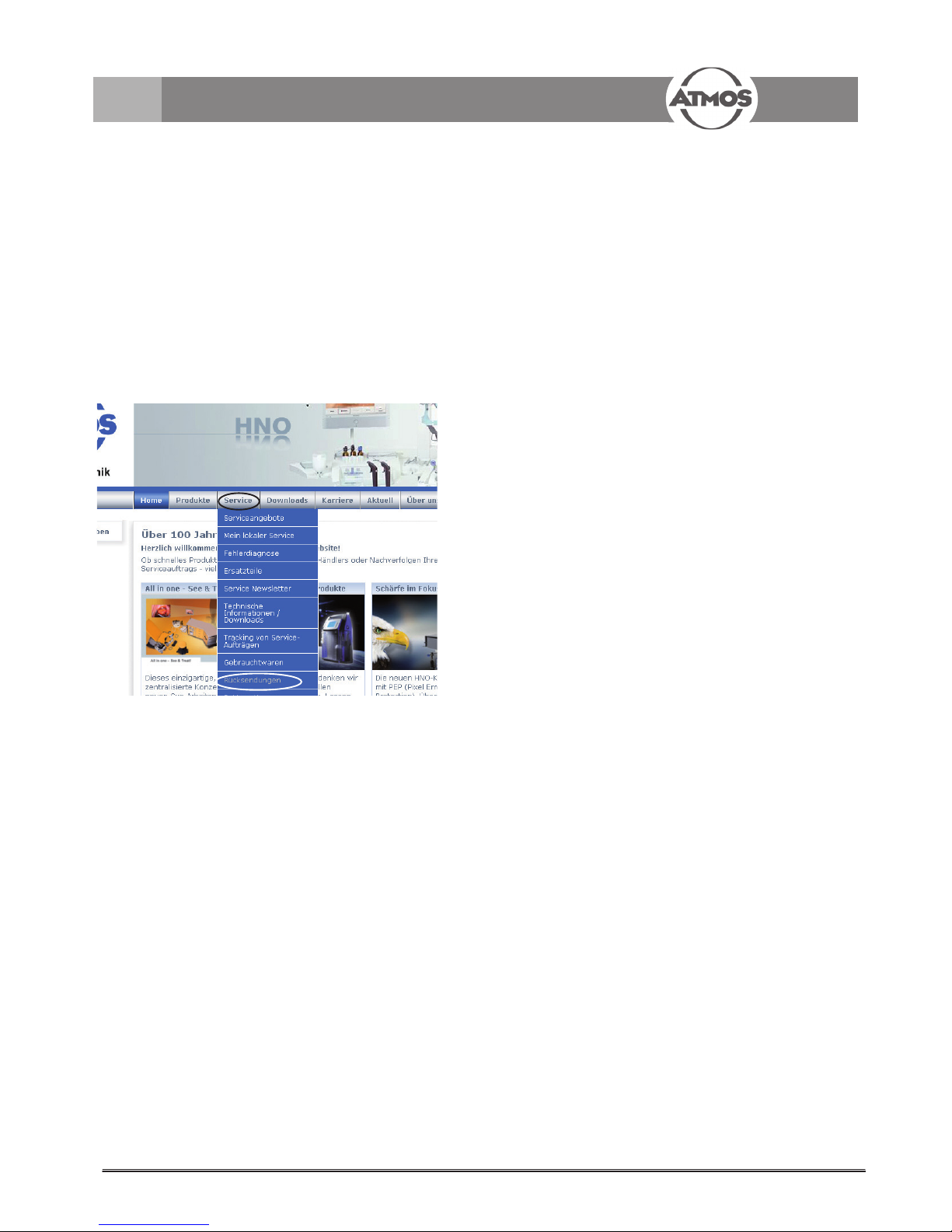
● Please document and report damages in transit
immediately. For complaints or return deliveries, please
use the enclosed form QD 434 Delivery complaint/
Return shipment. The form QD 434 can also be
downloaded from the internet www.atmosmed.de
(see Fig. 2).
● Ambient conditions:
Transport/Storage: +5...+40 °C;
05...95 % air humidity
non-condensing at air
pressure 700...1060 hPa
Operation: +15...+40 °C;
05...95 % air humidity
non-condensing at air
pressure 700...1060 hPa
Fig. 2
Page 6
6
!
■
●
→
click
click
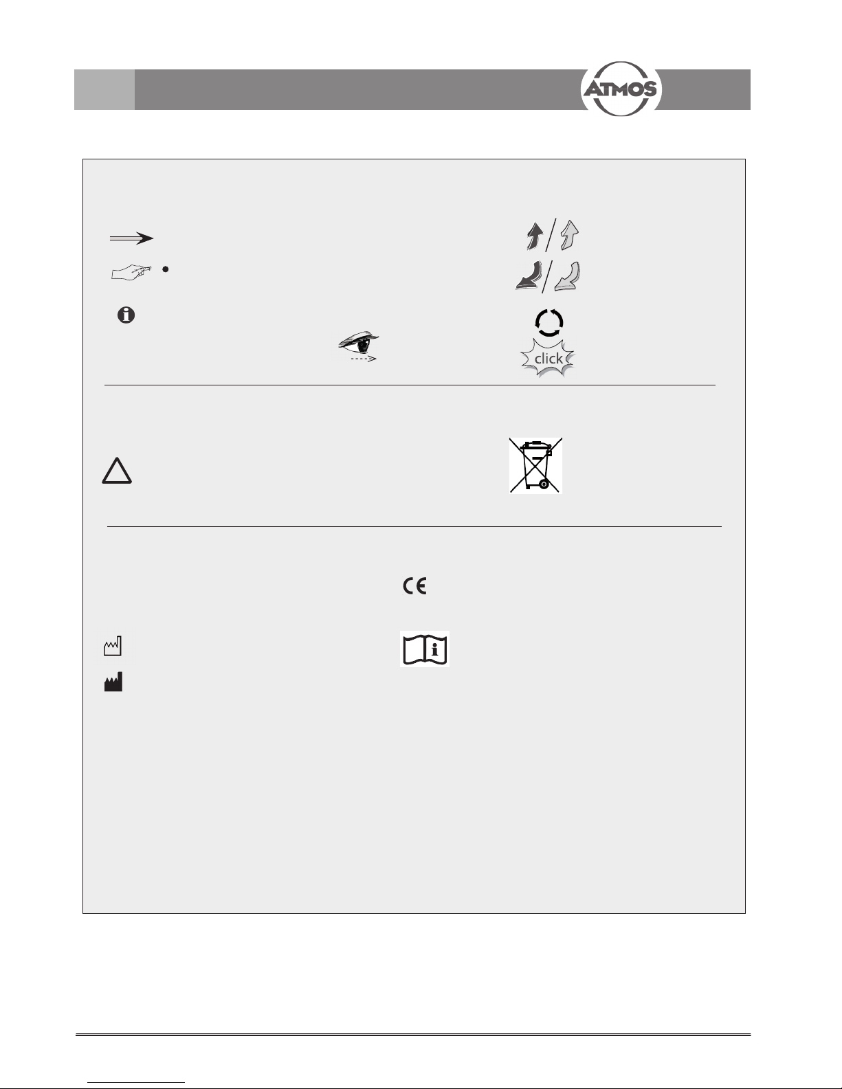
Pictures contained in this manual
Warning,
especial diligent notice!
Important notes
Symbols of the ATMOS Aqua clean
Serial number
Order number
Creation date
The CE sign shows that this
product meets the appropriate
requirements of the EC Directive
93/42 EEC.
REF
SN
Please observe operating instructions!
Proper disposal
Manufacturer
1.6 Explanation of pictures and symbols
1.0 Introduction
Short cuts / symbols contained in this manual
Please press where
the dot indicates
Subnumeration
Numeration
General information
Follow the arrows
whilst proceeding,
sequence
Replace
Check
Please read,
important information
Move, plug ... in this
direction
Engage, check correct
fi t
Turn, shift ... in this
direction
Page 7
7
2.0 For your Safety
Danger to the
device
● Do not allow any liquid to get into the unit. If
liquid has penetrated the unit, it may not be
operated again until it has been checked by
the customer service centre.
● The unit must be set up on a fi rm, level
surface.
● The main voltage specifi ed on the type plate must
match the power supply system.
● The unit may not be started:
• if cables or plugs are defective,
• if obvious defects might restrict safe
operation.
Prior to returning the device for repair to the
dealer you bought it, please clean it.
● Pay attention to the ambient conditions
described in chapter 1.5 Transport and
storage.
● Never plunge the unit into water, not even
when it is switched off.
● The device must be checked at regular inter-
vals regarding function and safety-relevant
damages, for example, wrap connection,
housing, etc.
● Never connect the unit to defective power
sockets or extension cables.
Avoid moisture on plug and switches.
● Prior to operation, please inspect the mains plug.
Only operate the device when the mains plug is
not damaged!
●
The unit, mains cable, accessories, connection
cables and hoses must be checked for damage
prior to starting up. Damaged cables and hoses
must be replaced immediately. Prior to use, check
the unit functions.
Danger of injury!
● Only persons instructed in medical use may
apply the ATMOS Aqua clean.
● The ATMOS Aqua clean may not be opera-
ted in splash water range and in explosion
hazardous areas.
General safety
information
• ATMOS cannot guarantee perfect functioning
neither will it be liable for damage to people or
property if:
• Any non-original ATMOS parts are used,
• the user instructions given in this manual are
not followed exactly or are disregarded,
• Assembly, resetting, alterations,extensions
and repairs are not carried out by people
authorised by ATMOS.
• there is any damage in transport due to
insuffi cient packing or due to residual water
in the device.
• Prior to starting up the ATMOS Aqua clean,
read these operating instructions carefully.
• The safety standard of the ATMOS Aqua clean
corresponds with recognized medical technical
regulations and the directives of the Medical
Devices Act.
• No warranty claims can be lodged for any da-
mage or malfunction which developed from the
use of third-party accessories or consumables.
• Only suitable for devices with a water
consumption of max. 550 ml/min and 2.2 bar
water pressure.
• The ATMOS Aqua clean may be operated only
in rooms used for medical purposes, but not
in areas subject to explosion hazards and in
oxygen rich environments.
● Always remove the plug from the wall socket
fi rst in order to disconnect the unit from the
mains. Only then may the connecting cable be
disconnected from the unit:
• before cleaning the unit,
• before leaving the room.
Never pull at the cable.
Never touch the plug or cable
with wet hands.
● Prior to any transport the water separation unit
must be fully emptied in order to prevent the
device from any damage.
● The device may not be exposed to frost neither
during transport, nor during storage.
● Close the main water tap at longer absence
(e.g. vacation) or unuse and switch off the
device.
!
● The device may not be operated without fi lter in
front of the water inlet.
● Do not lift the device at the cover.
Page 8

8
1
2
3
1
2
3
Fig. 4
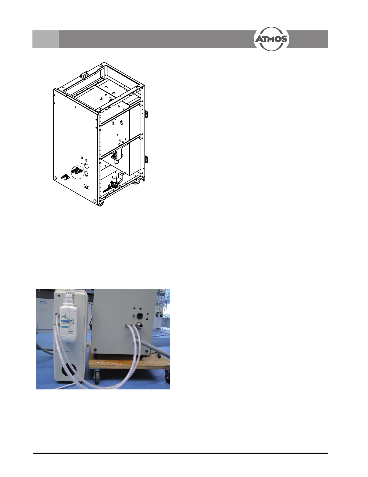
3.0 Setting up and starting
3.1 Installation in the auxiliary
housing
The device is mounted in a shapely housing next to the
treatment unit on a level and suffi ciently sustainable
surface.
Main switch:
It must be ensured that the power supply is
connected downstream of the main instrument /
practice switch.
Connect the device to a properly installed earthed contact
socket. Adhere to the connected load stated on the type
plate.
In case of unfi rm assembly, there is a danger of liquid
from the mixing container’s overfl ow spilling out and
activating the overfl ow sensor (see chapter 4.2).
Starting Sequence:
1. Open main water tap
2. Switch on ATMOS S 61 Servant
3. Switch on ATMOS Aqua clean
If error “F1” appears, switch the ATMOS S 61 Servant
off and on, until the error disappears.
3.2 Hose connections
Chemical bottle connection
PVC tubing
Ø internal = 2 mm
Ø outer = 4 mm
Connection to the water outlet
(supplying the instruments)
PVC tubing
Ø internal = 4 mm
Ø outer = 6 mm
Water connection (fresh water in drinking water
quality)
Permitted pressure at entry: 2-6 bar
PVC tubing (with KTW authorisation)
Ø internal = 6 mm
Ø outer = 8 mm
3.2.1 Initial connection of the
chemical bottle
Open the housing of the ATMOS Aqua clean and feed the
hose (Fig. 4) through the housing to the outside. Plug
the provided seal onto the bottle and insert the hose. Fix
the bottle in the provided support.
Fig. 3
1
Page 9
9
3.0 Setting up and starting
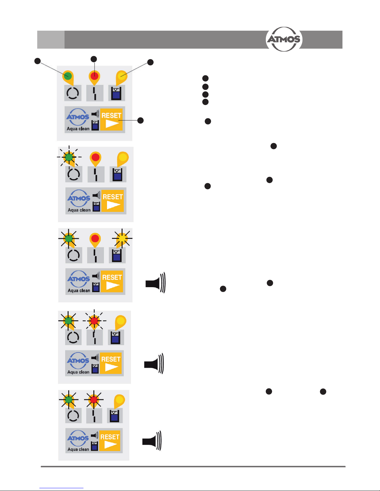
3.3 Explanation of the controls
Control light 1: Ready for use (green)
Control light 2: Fault (red)
Control light 3: Disinfectant sensor (yellow)
Alarm RESET button
Switch On/Checking routine: The green control signal
(Fig. 6) jitters:
During the system is switched on the ATMOS Aqua clean
automatically performs a checking routine. While this
procedure the control signal (Fig. 6) is blinking fast.
If an error occurs the unit is not activated and the error is
shown at the controls (see below). After successful checking routine, control signal 1 illuminates constant and the
unit is ready for operation.
The green control signal and the yellow signal
(Fig. 7) are illuminated and an alarm tone
sounds.
Cause: Disinfectant sensor indicates, that the processing
water is not being sterilised!
Action: Change the chemical bottle (see chapter 4.2.1)!
If the chemical bottle cannot be changed immediately,
the RESET button must be pressed to deactivate the
continuous alarm tone. The unit remains functional, and
does not interrupt the work. However, a short signal tone
still sounds periodically. If this error was only produced
by an air bubble, it will expire within the next trial by itself.
However, no decontamination takes place until the empty
chemical bottle is replaced with a full one (see chapter
4.2.1).
The green control signal is illuminated and the red
signal jitters and an alarm tone sounds (Fig. 8).
Cause: Level monitor in the mixing container is soiled
or there is no water supply!
Action: First of all, check if the main water tap resp. water
feed line is opened! Clean or replace the mixing container
probe (see chapter 4.2).
Consequence: All valves and the pump are switched off.
The alarm tone can be switched off by the RESET button.
After solving the problem the ATMOS Aqua clean can only
be activated again by switching the unit off and on.
The green control signal and the red signal
are illuminated and an alarm tone sounds (Fig. 9).
Cause: Defective double membrane pump or overfl ow!
Action: Clean the overfl ow sensor. Check the double
membrane pump and the electronic control system (see
chapter 4.2).
Consequence: All valves and the pump are switched off.
The alarm tone can be switched off by the RESET button.
After solving the problem the ATMOS Aqua clean can only
be activated again by switching the unit off and on.
1
2
3
4
4
1
1
3
1
2
1
2
1
2
3
4
Fig. 5
Fig. 6
Fig. 7
Fig. 8
Fig. 9
Page 10
10
3.4 Connection conditions for
ATMOS S 61 Servant
3.0 Setting up and starting
Scope of supply for option REF 530.2120.0
Article description REF Quantity
ATMOS Aqua clean 530.21210 1
Hose clamp 061.0060.0 2
Hose clamp 061.0061.0 2
Hose barb 8/8 Legris 000.0974.0 3
Hose barb 6/5 Legris 000.0988.0 2
Fabric tube 6x3; 1 m 005.0091.0 1
Fabric tube 8x3; 1 m 005.0020.0 1
Bottle support 1
Seal 1
ATMOS Green & Clean WK 534.3110.0 1
Starting Sequence:
1. Open main water tap
2. Switch on ATMOS S 61 Servant
3. Switch on ATMOS Aqua clean
If error “F1” appears, switch the ATMOS S 61 Servant
off and on, until the error disappears.
Fig. 10
Fig. 11
Page 11
11
3.5 Connection conditions
for irrigation and stimulation
devices
(Variotherm / Hygrotherm)
For operating an irrigation and stimulation device
the product, REF 502.1200.0, is required
Scope of supply:
Article description REF QTY
ATMOS Aqua clean 530.2121.0 1
Hose connection Vario-Aqua 502.1201.0 1
Hose connection HWA-Aqua 502.1202.0 1
Bottle support 1
Seal 1
ATMOS Green & Clean WK 534.3110.0 1
Starting Sequence:
1. Open main water tap
2. Switch on irrigation and stimulation device
3. Switch on ATMOS Aqua clean
If error “F1” appears, switch the irrigation and stimulation device off and on, until the error disappears.
3.0 Setting up and starting
Chemical bottle connection
PVC tubing
Ø internal = 2 mm
Ø outer = 4 mm
Connection to the water outlet
(supplying the instruments)
PVC tubing
Ø internal = 4 mm
Ø outer = 6 mm
Water connection (fresh water in drinking water
quality)
Permitted pressure at entry: 2-6 bar
PVC tubing (with KTW authorisation)
Ø internal = 6 mm
Ø outer = 8 mm
1
2
3
1
2
3
Fig. 12
Fig. 13. Connection to diagnostic device
Fig. 14. Water connection
Page 12

12
4.0 Cleaning and disinfection
4.1 Disinfectant /
Changing the chemical bottle
4.1.1 Disinfectant
(REF 534.3110.0)
For disinfection a 2% hydrogen peroxide solution with
added silver, ATMOS Green & Clean WK, is used. Hydrogen peroxide-based concentrates are particularly suitable
for reducing micro-organism levels in the water supply
because of their potent bactericidal and fungicidal action.
Hydrogen peroxide also show an outstanding ratio of
potential risk to disinfectant effi cacy, and present no risk
for the patient.
During each disinfecting operation in the ATMOS Aqua
clean system, a specifi ed amount of disinfected solution is
added to the 150 ml of water in the mixing container. This
provides the concentration of 0.0235% required for broadspectrum disinfection.
If the ATMOS Green & Clean WK bottle is completely
empty, an error message appears on the external indicator, stating that no more disinfectant solution can be
withdrawn. The empty bottle should be detached from the
fi tting tube on the ATMOS Aqua clean and replaced with a
new one.
Please note that only ATMOS Green & Clean WK
provides the concentration required for broadspectrum
disinfection.
The use of chemicals other than from ATMOS may damage
the ATMOS Aqua clean as well as other devices which are
connected.
Safety precautions: Keep out of the reach of children. In
case of contact with the eyes, rinse thoroughly with water.
In case of skin contact, wash with water. Store ATMOS
Green & Clean WK at room temperature (or +5°C to
max. +30°C) and preferably protected from light!
Composition: hydrogen peroxide, silver and less than 0.1%
stabilisers, water.
For any further information, please see the safety
data sheet!
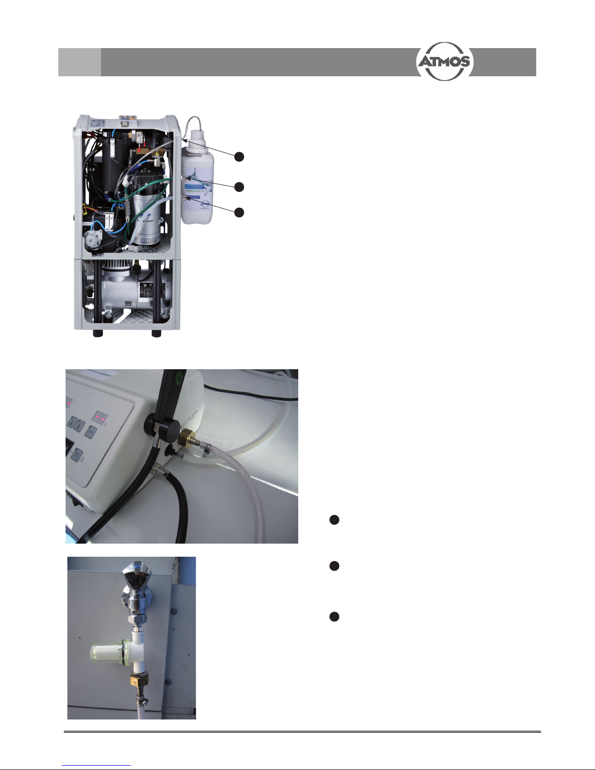
4.1.2 Changing the chemical bottle
Remove the chemical bottle from the unit (Fig. 16) . Pull gently
to remove the screw top and the attached tube which
extends into the bottle (Fig. 17) .
Remove the screw top from the new bottle of chemical, insert
the tube into it and screw back onto the bottle (Fig. 18).
Replace the bottle into the holder.
Fig. 15
Fig. 16
Fig. 17 Fig. 18
Page 13

13
4.0 Cleaning and disinfection
4.2 Care and cleaning
Additional programs:
Automatic emptying: For emptying the unit during operation the RESET button has to be held down for
approx. 8 sec. (control signal jitters) until a second
acoustic signal is activated. Then the green control
signal 1 jitters slowly. Supply container and pressure
container are empty if no more water comes out of the
unit. Now, the ATMOS Aqua clean can either be switched
off or the normal operation can be activated by holding
down the RESET button for another 8 sec.
Intensive decontamination: To increase the concentration of the chemicals as required, the intensive decontamination can be activated by holding down the RESET
button (control signal jitters) for approx.
4 sec. until the fi rst acoustic signal is activated. While
this procedure is taking place control signal jitters
and signal is illuminated. Afterwards the handle must
be oprated. With the next chemical dosing operation will
be delivered 3 doses of chemical, followed by 2 doses
each in the next 4 dosing operations. No chemical will be
added to the completing dosing in order that the normal
concentration is ensured with fi nalisation of the intensive
decontamination. Control signal 3 expires after the intensive decontamination and a short acoustic signal is activated. The ATMOS Aqua clean returns into normal operation.
Intensive decontamination is always recommended prior
to longer idle times like weekend or holiday and after treatment of patients with suspicion of HIV, HBV or HCV.
Remove water level probe from the mixing container
and clean or replace.
● Switch off main switch.
● Carefully pull probe up and out.
● Clean or replace probe. Check the electronic control
system.
● Replace the probe in the mixing container.
● Switch on main switch.
Check overfl ow sensor at the mixing container.
● Switch off main switch.
● Clean/dry overfl ow sensor . Check electrical
connections of the electronic control system
(see page 22).
● Check double membrane pump and the electronic
control system.
● Switch on main switch.
If this error exists further on, the double membrane is
probably broken, whereby the double membrane pump
(module 5) has to be replaced!
Surface disinfection
Please use ATMOS Green & Clean SK for the daily
surface disinfection .
1
2
3
4
4
1
1
1
1
2
3
4
1
2
Fig. 19
Fig. 20
Page 14

14
5.0 Maintenance
• Annual service inspection for the ATMOS Aqua clean with
service kit (service interval is also dependent on water
hardness!) This service contains a complete function
control of the device, exchange of the input fi lter (Fig.
21), test (if required exchange) of the water dosing valves
(Fig. 22) and magnetic valves , the water non-return
valve (Fig 22) as well as the tubes (Fig 22). Additionally, also an inspection (and if required cleaning) of the
mixing container (Fig. 22) and its probes needs to be
carried out.
• The safety-related checks acc. to IEC 62353 must be
performed at least every 12 months.
• ATMOS cannot guarantee perfect functioning neither will
it be liable for damage to people or property if:
• any non-original ATMOS parts are used,
• the user instructions given in this manual are not
followed exactly or are disregarded,
• assembly, resetting, alterations, extensions and
repairs are not carried out by people authorised by
ATMOS.
• No warranty rights shall exist in the event of damage or
failure caused by the use of non-ATMOS accessories or
non-ATMOS consumables.
• Check hoses and connections on any leakages at regular
intervals.
• Prior to sending in the device for repair it must be fully
emptied.
• For an extensive fi nal inspection of the device during
repair, please include all accessories into the delivery.
5.1 Regular inspections
• Functional and tidiness inspections are required after any
work at the ATMOS Aqua clean. Safety-related inspections are to be performed along with the inspection of the
connected treatment unit or at least once a year (acc. to
BGVA3). Furthermore the control and safety functions
must be checked.
1
1
2
3
4
5
Fig. 21
Fig. 22
1
1
2
3
4
5
Page 15

15
6.1 Retrofi tting at ATMOS S 61 Servant
For retrofi tting at the ATMOS S 61 Servant the product,
REF 530.2120.N is required.
Scope of supply:
Article description REF QTY
ATMOS Aqua clean 530.2121.0 1 piece
Hose clip 061.0060.0 2 pieces
Hose clip 061.0061.0 2 pieces
Pressure reducer, mini 502.0955.0 1 piece
Lock nut M4 052.0024.0 2 pieces
Hexagon head screw
DIN 933 - M4 x 12 051.0297.0 2 piece
Disk DIN 125 - A 4,3 053.0001.0 4 pieces
Bulkhead connector
straight Rd8 Legris 000.0978.0 1 piece
Bulkhead connector
straight Rd6 Legris 000.0980.0 1 piece
Screw in union
straight Rd4/1/8“ Legris 000.0977.0 2 pieces
Screw in union
straight Rd8/1/8“ Legris 000.0976.0 1 piece
Hose barb 8/8 Legris 000.0974.0 3 pieces
Screw in union
straight Rd6/1/8“ Legris 000.0975.0 1 piece
Hose barb 6/5 Legris 000.0988.0 2 pieces
Screw in union
L Rd8/1/8“ Legris 000.0981.0 1 piece
Mounting plate 530.2122.0 1 piece
Valve mounting angle 530.2123.0 1 piece
Disk 22 x 16 x 1 053.0113.0 2 pieces
Disk 22 x 18 x 1 053.0114.0 2 pieces
Hose quick connector
T 4-4-4 000.0513.0 1 piece
Bottle support 1 piece
Seal 1 piece
ATMOS Green & Clean WK 534.3110.0 1 bottle
Hose RD.I. 6,0 x 3,0 000.0091.0 1000 mm
Hose RD.I. 8,0 x 3,0 005.0020.0 1000 mm
Hose, Rilsan RD.A. 8,0 005.0025.0 240 mm
Hose, Rilsan RD.A. 6,0 005.0173.0 200 mm
Hose, Rilsan RD.A.4,0 005.0026.0 450 mm
Hose, Rilsan RD.A.4,0 005.0026.0 250 mm
Hose, Rilsan RD.A.4,0 005.0026.0 680 mm
6.0 Retrofi tting
1
2
3
4
5
6
7
8
9
10
17
16
15
14
13
12
11
18
19
Page 16

16
6.0 Retrofi tting
180
30
591
X
18 mit Schälbohrer bohren
16 mit Schälbohrer bohren
X
1 : 1
18
7
8
17
9
9
12
3
1
11
16
15
19
2
13
10
11
14
Fig. 23
A
B
A Assemble the mounting plate and build it in.
B Exchange existing plate against mounting plate .
15
16
Please drill the required holes into ther rear part of the housing as per the drawing.
Starting Sequence:
1. Open main water tap
2. Switch on ATMOS S 61 Servant
3. Switch on ATMOS Aqua clean
If error “F1” appears, switch the ATMOS S 61 Servant
off and on, until the error disappears.
diam. 18 mm, drill with hole cutter
diam. 16 mm, drill with hole cutter
4
5
6
Page 17

17
6.0 Retrofi tting
6.1.1 Tubing
Article description REF Length
Hose RD.I. 6,0 x 3,0 000.0091.0 1000 mm
Hose RD.I. 8,0 x 3,0 005.0020.0 1000 mm
Hose, Rilsan RD.A. 8,0 005.0025.0 240 mm
Hose, Rilsan RD.A. 6,0 005.0173.0 200 mm
Hose, Rilsan RD.A.4,0 005.0026.0 450 mm
Hose, Rilsan RD.A.4,0 005.0026.0 250 mm
Hose, Rilsan RD.A.4,0 005.0026.0 680 mm
Hose, Rilsan RD.A.8,0 005.0025.0 130 mm
1
2
3
4
5
6
7
1
2
3
4
5
6
7
Fig 24
8
8
water connection
non-return valve
Page 18

18
6.1.2 Retrofi tting of a delay PCB
● Drilling of the holes for the fi xing bolts. Place the PCB on the carrier
plate and mark the drillings. Afterwards drill the holes with a 3.5 mm
drill.
● Screw the 4 bolts M3x10 including washer and locknut.
● Tighten the PCB with 4 lens head screws 3x5.
● Fix the connecting cable (REF 530.2124.0) as per the drawing.
● Connect the existing Aquastop to the PCB, REF 011.1314.0.
6.0 Retrofi tting
Fig. 25
Fig 26
Page 19

19
6.0 Retrofi tting
6.1.3 Delayed switching circuit for Aquastop
011.1314.0
GND
V+
230V
12V =
12V
PCB for 230V switching
230V
Control PCB
ST1
011.1307.0
Aquastop Verzögerung
Delay for Aquastop switching
spülbeh
sekretbeh
reserve
Steuerplatine
Control PCB
530.1149.0
S5c
S5
530.2124.0
+12V
GND
Page 20

20
6.0 Retrofi tting
6.1.4 Water connections
Aquastop
Wasserzulauf
Water Inlet
Aquaclean
530.2121.0
Eingang
Inlet
Ausgang
Outlet
Schlauchschelle
Hose Clamp
061.0060.0
Gewebeschlauch 8 mm
Fabric-Reinforced Hose 8mm
005.0091.0
Gewebeschlauch 6 mm
Fabric-Reinforced Hose 6mm
005.0020.0
Schlauchtülle 8mm
Spout 8mm
000.0974.0
Schlauchtülle 6mm
Spout 6 mm
000.0988.0
Schottverschraubung 6/6
Bulkhead connector 6/6
000.0980.0
Schottverschraubung 8/8
Bulkhead connector 8/8
000.0978.0
Ursprünglich am T-Stück
Originally on T-Connector
Druckerhöhung auf 3,5 bar
Pressure elevation to 3.5 bar
Schlauch RILSAN 8mm
Hose RILSAN 8mm
005.0025.0
Schlauch RILSAN 8mm
Hose RILSAN 8mm
005.0025.0
Schlauchverbinder L 8-8
Hose Connector L 8-8
000.0252.0
Ohrspülmodul
Ear Irrigation Module
Manometer
Schlauch RILSAN 6mm
Hose RISAN 6mm
005.0173.0
Schlauchverbinder 1/8”/6
Hose Connector 1/8”/6
000.0975.0
Schlauchverbinder 1/8”/4
Hose Connector 1/8”/4
Schlauch RILSAN 4mm
Hose RILSAN 4mm
005.0026.0
Druckminderer
Pressure Reducer
502.0955.0
2 bar2 bar
Bereits vorhanden
Already existing
Neue zu installierende Teile
New parts to be assembled
Befüllung Schlauchspülbehälter
Refilling of hose rinsing container
Page 21

21
6.2 Retrofi tting at
ATMOS Servant 5 / 5 C
For retrofi tting at the ATMOS Servant 5 / 5 C
the article, REF 510.2150.0, is required.
Scope of supply:
Article description REF Qty.
ATMOS Aqua clean 530.2121.0 1 piece
Hose clip 061.0060.0 4 pieces
Pressure reducer, mini 502.0955.0 1 piece
Bulk head connector
straight Rd8 000.0978.0 1 piece
Bulk head connector
straight Rd6 000.0980.0 1 piece
Screw in union
straight Rd4/1/8“ 000.0977.0 1 piece
Screw in union
straight Rd 6/1/8“ 000.0975.0 1 piece
Hose barb 8/8 000.0974.0 2 pieces
Hose barb 6/5 000.0988.0 2 pieces
Disk 22 x 16 x 1 053.0113.0 2 pieces
Disk 22 x 18 x 1 053.0114.0 2 pieces
Hose quick connector
T RD8-8-8 000.0253.0 1 piece
Hose quick connector
L RD8-8 000.0252.0 1 piece
Hose Rd.I. 6,0 x 3,0 005.0091.0 1000 mm
Hose Rd.I. 8,0 x 3,0 005.0020.0 1000 mm
Hose, Rilsan Rd.A.4,0 005.0026.0 1000 mm
Hose, Rilsan Rd.A.6,0 005.0173.0 200 mm
Hose, Rilsan Rd.A.8,0 005.0025.0 1000 mm
Bottle support 1 piece
Seal 1 piece
ATMOS Green & Clean WK 534.3110.0 1 bottle
6.2.1 Drilling
Note:
When drilling the holes for the screwed connection (water
in- / outlet into and out of the ATMOS Servant 5 housing)
it is important to consider the equipment of the ATMOS
Servant 5 which needs to be retrofi tted.
Here we can only provide some general information and
recommendations because of the many different version
currently in use.
6.0 Retrofi tting
3
4
1
2
3
4
5
6
7
8
9
10
17
16
15
14
13
12
11
Fig. 28
Starting Sequence:
1. Open main water tap
2. Switch on ATMOS Servant 5 / 5 C
3. Switch on ATMOS Aqua clean
If error “F1” appears, switch the ATMOS Servant 5/5 C
off and on, until the error disappears.
Fig. 27
Page 22

22
6.0 Retrofi tting
11
10
3
1
7
12
5
2
6
9
4
8
1
Fig. 29
Fig. 30
6.2.2 Tubing
6.2.3 Add-on kit
heating module
existing new
Page 23

23
6.0 Retrofi tting
6.2.4 Delayed switching circuit for Aquastop until 2005
011.1314.0
GND
V+
230V
12V =
Inline Cable Fuse
T 1A slow
Schwammschalter
Sponge Switch
bl
br
bl
br
bl
br
12V
PCB for 230V switching
230V
Control PCB
ST6/ST8/ST9
ST1
ST2
KL1
Steuerplatine Servant 5
Control PCB Servant 5
510.0040.0
011.1307.0
Aquastop Verzögerung
Delay for Aquastop switching PCB
Verzögerungsschaltung für Aquastop Servant 5 bis Bj. 2005
Delayed switching circuit for Aquastop on Servant 5 until 2005
Ursprünglicher Anschluß Aquastop.
Original Aqustop connection
ST15
ST11
Vorhandenes Kabel Stirnlampenhaken
Existing cable for headlamp suspension
510.2152.0
S5c
S5
510.2153.0
+12V
GND
Page 24

24
6.0 Retrofi tting
6.2.4.1 Delayed switching circuit for Aquastop from 2006
011.1314.0
GND
V+
230V
12V =
12V
PCB for 230V switching
230V
Control PCB
ST1
011.1307.0
Aquastop Verzögerung
Delay for Aquastop switching
Verzögerungsschaltung für Aquastop
Delayed switching circuit for Aquastop on
Servant 5 from 2006 / Servant 5c / Systema II
Saughandgriff
Suction Handle
Drucklufthandgriff
Pressed Air Handle
Beckenspülung
Bowl rinsing
Pegelschalter
Level Switch
Schalter Schlauchspülbehälter
Microswitch Hose Rinsing Bottle
Ohrspülmodul
Ear Irrigation Module
Fallrohrelektroden
Drain Pipe Electrodes
Füllstandselektroden Sekretbehälter
Level Electrods Secretion Jar
Taster Spiegelschnellerwärmer
Push Button Mirror Quick Heater
Sicherheitsschalter Abdeckklappe
Cover switch
Steuerplatine
Control PCB
Servant 5c / Systema II
506.6100.0
Ursprünglicher Anschluß Aquastop
Original Aqustop connection
+
Ursprüngliches Kabel vom Ohrspülmodul
Original cable from ear irrigation module
510.2152.0
S5c
S5
510.2153.0
+12V
GND
Page 25

25
6.0 Retrofi tting
6.2.5 Water connections until 2005
Spülung Ohrspülschale
Basin Rinsing
Befüllung Spülbehälter
Rinsing bottle refilling
AQUACLEAN
530.2121.0
Gewebeschlauch 8mm
Fabric-Reinforced Hose 8mm
005.0091.0
Gewebeschlauch 6mm
Fabric-Reinforced Hose 6mm
005.0091.0
Schlauchtülle 8mm
Spout 8mm
000.0974.0
Schlauchtülle 6mm
Spout 6 mm
000.0988.0
Schlauchschelle
Hose clamp
061.0060.0
Schottverschraubung 6/6
Bulkhead connector 6/6
000.0980.0
Schottverschraubung 8/8
Bulkhead connector 8/8
000.0978.0
Ventilblock
Valve Block
Aquastop
Wasserfilter
Water Filter
502.0890.0
Schlauch RILSAN 8mm
Hose RILSAN 8mm
005.0025.0
Schlauch RILSAN 8mm
Hose RILSAN 8mm
005.0025.0
Druckminderer
Pressure reducer
Schlauch RILSAN 6mm
Hose RILSAN 6mm
005.0173.0
Schlauchschnellverbinder I 1/8”/6
Hose Quick Connector I 1/8”/6
Anschluß Zulauf Heizblock Ohrspülung
Inlet connectot heating block ear irrigation
Wasserdruck
Water pressure
Wasserzulauf
Water Inlet
Eingang
Inlet AQUACLEAN
8 mm
Ausgang
Outlet AQUACLEAB
6 mm
This branchwas connected at the pressure reducer before
Dieser Zweig war vorher mit dem Druckminderer verbunden
Wasseranschluß Servant 5 bis BJ 2005
Water connections Servant 5 until 2005
Die Veränderungen sind rot gekennzeichnet
The modifications are marked with red colour
2 bar
Page 26

26
6.0 Retrofi tting
6.2.5.1 Water connections from 2006
Aquastop
Wasserzulauf
Water Inlet
Aquaclean 530.2121.0
Ohrspülmodul
Ear Irrigation Module
Bereits vorhanden
Already existing
Neue zu installierende Teile
New parts to be assembled
Eingang
Inlet
Ausgang
Outlet
Wasserfilter
Water Filter
Vorhandener Druckminderer
Existing Pressure Reducer
Anschlußleiste Magnetventile
Valve bank
Manometer
Schlauchschelle
Hose Clamp
061.0060.0
Gewebeschlauch 8 mm
Fabric-Reinforced Hose 8mm
005.0091.0
Gewebeschlauch 6 mm
Fabric-Reinforced Hose 6mm
005.0020.0
Schlauchtülle 8mm
Spout 8mm
000.0974.0
Schlauchtülle 6mm
Spout 6 mm
000.0988.0
Schottverschraubung 6/6
Bulkhead connector 6/6
000.0980.0
Schottverschraubung 8/8
Bulkhead connector 8/8
000.0978.0
Druckminderer
Pressure Reducer
502.0955.0
Schlauch RILSAN 6mm
Hose RISAN 6mm
005.0173.0
Schlauchverbinder 1/8”/6
Hose Connector 1/8”/6
000.0975.0
Schlauch RILSAN 4mm
Hose RILSAN 4mm
005.0026.0
Schlauchverbinder 1/8”/4
Hose Connector 1/8”/4
Schlauch RILSAN 8mm
Hose RILSAN 8mm
005.0025.0
Schlauch RILSAN 8mm
Hose RILSAN 8mm
005.0025.0
Schlauch RILSAN 8mm
Hose RILSAN 8mm
005.0025.0
Schlauchverbinder L 8-8
Hose Connector L 8-8
000.0252.0
Schlauchverbinder T 8-8-8
Hose Connector T 8-8-8
000.0253.0
Anschluß Wasser / Water Circuit
Servant 5c / Systema II / Servant 5 ab 2006
2 bar
Page 27

27
7.0 Troubleshooting
Prior to dispatch, the ATMOS Aqua clean was subjected to an extensive functional test. If, nevertheless, a failure should
appear, you may possibly clear it yourself if you follow these notes:
Error Possible reason Troubleshooting
Device/pump does not
start up
– Loose power plug – Check connection to supply socket
– No mains voltage – Check inbuilding fuse
– Check whether power plug on
the unit is loose
– Defective fuse at the power input – Exchange fuse
8.0 Accessories and Spare Parts
Article description REF
ATMOS Green & Clean WK 534.3110.0
Service kit 069.0260.0
Page 28

28
9.0 Technical information
9.1 Structure
To ensure that it meets the most stringent in-service
requirements, the ATMOS Aqua clean consists of several
modules:
Module 1 - Electronic control system.
Module 2 - Pressure container; this generates the
water pressure. In addition to the container, this
module contains a magnetic valve, a pressure-sensitive
switch and a non-return valve.
Module 3 - Membrane pump; includes pump and
non-return valve.
Module 4 - Mixing container; here, water is mixed
with the disinfectant (after the cascade section).
This module includes the container, fi lling and
overfl ow sensor, 2 magnetic valves and the disinfectant
sensor.
Module 5 - Double membrane pump and membrane
break sensor.
Module 6 - Water unit; consists of a fl ow rate limiter
and dosing valves.
Module 7 - Compressed air unit; this is a pressure
regulator.
Module 8 - Auxiliary installation housing; consists
of housing, fi xing plate, main water tap with fi lter
(100 μm), compressed-air service module, transformer
and main switch.
Fig. 31, module 1
Fig. 32, module 2
Fig. 33, module 3
Fig. 34, module 4 and 5
Fig. 35, module 6
Fig. 36, module 7 Fig. 37, module 8
module 5
Page 29

29
9.0 Technical
9.2 Electrical connections, circuit board
Overfl ow sensor (yellow)
Pressure-sensitive switch (red)
Mixing container probe (yellow/red/black)
Disinfectant sensor (green)
Level monitor in the pressure container (blue)
Air cushion valve on the pressure container (black) MV4
External display
Chemical valve (black) MV3
Water safety valve 5 (brown)
Pump motor connection
Membrane breaking (yellow)
Power supply plug 24 V AC (orange)
Water dosing valve 1 (brown)
Compressed air valve (black) MV2
Main fuse 3,15 A T
When replacing the fuses, always use the same
type!
9.3 Wiring diagram
see Fig. 39.
1
2
3
4
5
6
7
8
9
10
11
12
13
14
15
1
2
3
4
5
6
7
8
9
10
11
12
13
14
15
!
Fig. 38
Fig. 39
Page 30

30
Issue of technical data: 21.09.2010
10.0 Technical specifi cations
Voltage: 230 V AC (add-on device)
Frequency: 50/60 Hz
Maximum power consumption: 0.8 A
Permitted water pressure: 2-6 bar
Operating pressure (water): 2.2 bar
Operating pressure (air): 4 bar
Maximum water fl ow rate: 550 ml/min
Water quality: drinking water
Disinfectant: ATMOS Green & Clean WK
Hydrogen peroxide, 2% solution
Mixing ratio: 1:85 standard setting
1:42 intensive decontamination
Working solution: 235 ppm
Overall dimensions: (H x W x D): 550 x 265 x 160 mm
Fig. 40
Page 31

31
11.0 Disposal
● The ATMOS Aqua clean does not contain any hazardous materials.
● The housing is recyclable.
● Device and accessories must be decontaminated prior to disposal.
● Please take care on a careful separation of the different materials.
● Please observe national disposal regulations (e.g. waste incineration).
Disposal within the EC
The device described above is a high-quality medical product with a long service life. After its life cycle it must
be disposed of professional. According to the EC directives (WEEE and RoHS) the device may not be disposed of in
domestic waste. Please observe existing national laws and rules for disposal of old devices.
Disposal within the Federal Republic of Germany
In the Federal Republic of Germany the law for electrical devices (ElektroG) rules the disposal of electrical devices.
In order to guarantee a proper disposal of your old device, please either pass on your old device to your specialised dealer
or send it directly to ATMOS MedizinTechnik for a professional disposal.
Prior to disposal the device surface must be disinfected.
Page 32

32
12.0 Notes on EMC
12.1 Guidelines and Manufacturer‘s Declaration - Emissions
The ATMOS Aqua clean is intended for use in the electromagnetic environment specifi ed below.
The customer or user of the ATMOS Aqua clean should ensure that it is used in such an environment.
■ Medical electrical equipment is subject to special precautions with regard to EMC and must be installed acc.
to following EMC notes.
■ Portable and mobile HF communication facilities can influence medical electrical equipment.
■ The use of other accessories, other converters and cables than stated may lead to an increased emission
or a reduced interference immunity of the equipment or system.
Emissions Test Compliance Electromagnetic Environment - Guidance
RF Emissions
CISPR 11
Group 1 The ATMOS Aqua clean uses RF energy only for
its internal function. Therefore, its RF emissions are
very low and are not likely to cause any interference
in nearby electronic equipment.
RF Emissions
CISPR 11
Class B
The ATMOS Aqua clean is suitable for use in all establishments, including domestic, and those directly
connected to the public low-voltage power supply
network that supplies buildings used for domestic
purposes.
Harmonics IEC 61000-3-2 Class A
Flicker
IEC 61000-3-3
Compliance
12.2 Guidelines and Manufacturer‘s Declaration - Immunity for
ATMOS Aqua clean
The ATMOS Aqua clean is intended for use in the electromagnetic environment specifi ed below. The customer or
user of the ATMOS Aqua clean should ensure that it is used in such an environment.
Immunity Test
IEC 60601Test Level
Compliance Level
Electromagnetic Environment - Guidance
ESD
IEC 61000-4-2
± 6 kV Contact
± 8 kV Air
± 6 kV Contact
± 8 kV Air
Floors should be wood, concrete,
or ceramics tile. If fl oors are syn-
thetic, the relative humidity should
be at least 30%.
EFT
IEC 61000-4-4
± 2 kV Mains
± 1 kV I/Os
± 2 kV Mains
not applicable
Mains power quality should be that
of a typical commercial or hospital
environment.
Surges
IEC 61000-4-5
± 1 kV
asymmetric
± 2 kV
symmetric
± 2 kV
asymmetric
± 2 kV
symmetric
Mains power quality should be that
of a typical commercial or hospital
environment.
Power Frequency
50/60 Hz
Magnetic fi eld
IEC 61000-4-8
3 A/m not applicable Power frequency magnetic fi elds
should be that of a typical commercial or hospital environment.
The device may not be used directly next to other devices or piled up with other devices.
If operation next to or piled with other devices is necessary, please watch the device to check its intended
operation in this arrangement.
Page 33

33
Immunity Test
IEC 60601Test Level
Compliance Level
Electromagnetic
Environment - Guidance
Voltage Dips / Dropout
IEC 61000-4-11
< 5 % UT
(> 95 % Dip of the UT)
for 0.5 Cycle
40 % U
T
(60% Dip of the UT)
for 5 Cycles
70% U
T
(30 % Dip of the UT)
for 25 Cycles
< 5 % UT
(>95 % Dip of the U
T
)
for 5 s
< 5 % UT
(> 95 % Dip of the UT)
for 0.5 Cycle
40 % U
T
(60% Dip of the UT)
for 5 Cycles
70% U
T
(30 % Dip of the UT)
for 25 Cycles
< 5 % UT
(>95 % Dip of the U
T
)
for 5 s
Mains power quality should be
that of a typical commercial or
hospital environment. If the user of
the ATMOS Aqua clean demands
continued function even in case of
interruptions of the energy supply,
it is recommended to supply the
ATMOS Aqua clean from an
uninterruptible current supply or a
battery.
NOTE U
T
is the mains alternating current prior to application of the test levels.
12.0 Notes on EMC
12.3 Guidelines and Manufacturer´s Declaration - Immunity
The ATMOS Aqua clean is intended for use in the electromagnetic environment specifi ed below. The customer or
user of the ATMOS Aqua clean should ensure that it is used in such an environment.
Immunity Test
IEC 60601Test Level
Compliance Level
Electromagnetic Environment Guidance
Conducted RF
IEC 61000-4-6
3 V
eff
150 kHz to 80 MHz
3 V
Portable and mobile communications
equipment should be separated from the
ATMOS Aqua clean incl. the cables by no
less than the distances calculated/listed
below.
Recommended distances:
d = 3,5/3√ P
d = 3,5/3√ P for 80 MHz up to 800 MHz
d = 7/3√ P for 800 MHz up to 2,5 GHz
where „P“ is the max. power in watts (W)
and D is the recommended separation
distance in meters (m).
Field strengths from fi xed transmitters, as
determined by an electromagnetic site (a)
survey, should be less than the compliance level (b).
Interference may occur in the vicinity of
equipment containing following symbol
Radiated RF
IEC 61000-4-3
3 V/m
80 MHz to 2.5 GHz 3 V/m
Page 34

34
12.4 Recommended separations between portable and mobile RF Communications
equipment and the ATMOS Aqua clean
Recommended separations between portable and mobile RF Communications
equipment and the ATMOS Aqua clean
The ATMOS Aqua clean is intended for use in electromagnetic environment in which radiated disturbances are
controlled. The customer or user of the ATMOS Aqua clean can help prevent electromagnetic interference by
maintaining a minimum distance between portable and mobile RF Communications equipment and the ATMOS
Aqua clean as recommended below, according to the maximum output power of the communications equipment.
Separation distance, depending on transmit-frequency m
Nominal output of the
transmitter
W
150 kHz up to 80 MHz
d = 3,5/3√ P
80 MHz up to 800 MHz
d = 3,5/3 √ P
800 MHz up to 2,5 GHz
d = 7/3 √ P
0,01 0,12 0,12 0,24
0,1 0,37 0,37 0,74
1 1,2 1,2 2,4
10 3,69 3,69 7,38
100 11,66 11,66 23,32
For transmitters for which the maximum nominal output is not indicated in the above table, the recommended
separation distance d in meters (m) can be determined using the equation belonging to the respective column
whereas P is the maximum nominal output of the transmitter in watts (W) acc. to manufacturer´s specifi cation.
NOTE 1 With 80 MHz and 800 MHz the higher frequency range applies.
NOTE 2 These guidelines might not be applicable in any case. The propagation of electromagnetic sizes is
infl uenced by absorptions and refl ections of buildings, objects and people.
NOTE 1 With 80 MHz and 800 MHz the higher frequency range applies.
NOTE 2 These guidelines might not be applicable in any case. The propagation of electromagnetic sizes is
infl uenced by absorptions and refl ections of buildings, objects and people.
a The fi eld strength of stationary transmitters, such as base stations of cellular phones and mobile terrain radio
equipment, amateur radio transmitters, cbm broadcast and TV stations cannot be predestined exactly.
To determine the electromagnetic environment in regard to stationary transmitters, a study of the location is to
be considered. If the measured fi eld strength at the location where the ATMOS Aqua clean is used exceeds
the above compliance level, the ATMOS Aqua clean is to be observed to verify the intended use.
If abnormal performance characteristics are noted, additional measures might be necessary, e. g. a changed
arrangement or another location for the device.
b Within the frequency range of 150 kHz to 80 MHz the fi eld strength is to be below 3 V/m.
12.0 Notes on EMC
Page 35

35
For your notes
Page 36

MedizinTechnik
This document is copyrighted. Duplication, translations, microlming and savings on electronic systems, particularly for commercialpurposes
are illegal without prior agreement of the manufacturer. All compiled data are based on manufacturers instructions. All logos,
product names and designations used in this document are property of the respective manufacturer.
We do not take over any warranty and liability in the case of missing inscriptions. Subject to modications and amendments.
1. General:
Our General Standard Terms and Conditions apply exclusively. Client’s
terms and conditions which are contrary to or deviate from our General
Standard Terms and Conditions are not recognised unless their validity
is explicitly confirmed in writing. Our General Standard Terms and
Conditions also apply even if we deliver to clients without reservation,
in the knowledge of the client’s contrary terms and conditions. Our
General Standard Terms and Conditions also apply to all future business
with that client.
2. Proposal - Order Confirmation
Our proposals are subject to change without notice unless otherwise
stated in our order confirmation. Each order is only accepted by us
following our written order confirmation.
3. Orders
Every order requires an exact description of all of our product’s details.
We assume no liability for errors and damage caused by inaccurate or
incomplete ordering details.
4. Prices
Unless otherwise stated in the order confirmation, our prices in the
order confirmation are ex factory prices and exclude packaging and
value added tax. Packaging is charged separately at cost price in the
invoice. Value added tax is charged separately in the invoice according
to the legal rate on the invoice date. We reserve the right to change
prices appropriately should price reductions or increases, especially
due to wage settlements, changes in the price of materials or currency
fluctuations, be incurred. Proof of such changes will be provided for the
client on request.
5. Payment Conditions - Balancing
Unless otherwise stated in the order confirmation, our invoices
are payable with a 3% discount within 10 days (except for repair and
assembly services) or within 21 days from the invoice date net cash;
money receipts is decisive for complying with this term. We are entitled
to charge interest after the due date at a rate 2% above the relevant
basic interest rate of the German Federal Bank. Should the client have
payment arrears, we are entitled to charge interest on arrears at a rate
5% above the relevant basic interest rate of the German Federal Bank.
Should we be able to prove higher damages due to arrears, we are also
entitled to claim these. The client only has the right to balance invoices
against its own claims should such claims be confirmed in a court of
law or recognised by us. The client does not have the right of retention
due to disputed counterclaims.
6. Delivery Periods
Fulfilment of our delivery duties requires the punctual and proper
fulfilment of the client’s duties. The right to defense on the grounds of an
unfulfilled contract is reserved.Should the client default in accepting the
goods delivery or breach other cooperation duties, we are entitled either
to withdraw from the contract or claim compensation for any increased
costs incurred up to that time without setting a further deadline. The right
to make further claims is reserved. Furthermore, in such cases, the risk
of coin-cidental destruction or a coincidental deterioration in the quality
of the delivered goods is transferred to the client in the case of default
in accepting such goods or payment arrears. Acts of God or stoppages
(due to insufficient supplies of material, industrial disputes etc.) entitle
us either to demand an appropriate extension of delivery periods or to
partly or entirely dissolve the delivery contract. This does not give the
client the right to claim damages. We have fulfilled delivery periods if the
delivery goods have left our factory or the client has been informed of
the goods’ readiness for delivery within such delivery periods. Delivery
periods stipulated by the client are not recognisedby us unless they
form part of our order confirmation. We adhere to legal terms and
conditions in cases where, as a result of an undue delay in the delivery
for which we are liable, the client is entitled to claim that his interests
in a continued fulfilment of the contract have ceased. We also adhere
to legal terms and conditions should a delay in delivery be caused by
deliberate or grossly negligent action by us or our representatives for
which we are responsible. We are also responsible for such actions by
our representatives or agents. Should the delivery delay not be caused
by our deliberate infringement of contractual duties for which we are
responsible, our liability is limited to damage which is regarded as typical
for that case. We are liable according to the legal terms and conditions if
and in so far as the delivery delay for which we are responsible is caused
by an infringement of a substantial contractual duty. In such cases, our
liability is also limited to damage which is regardedas typical for that
case. Should the delivery delay be caused by a culpable infringement
of non-substantial contractual duties, our client is also entitled to claim
a one-off damage compen-sation worth 3 percentage points of the
delivery value of the goods for each week’s delay, up to a maximum
which is no higher than 15 percentage points of the delivery value of
the goods
7. Delivery - Familiarisation
In the case of the delivery of devices for the medico-technical industry
which require assembly and/or familiarisation for the final customer using
specialist trade personnel (such as Ear, Nose and Throat Apparatus and
Suction Units), we reserve the right to deliver the goods exclusively to
the relevant specialist traders. Should the trader not carry out assembly
and/or familiarisation for the final customer, this is carried out by us. In
such cases, we reserve the right to charge the client for the additionally
created costs. Our specialist traders operate a recording system so
that, if necessary, our products can be traced to the final customer. The
specialist trader undertakes to immediately report to us all events and
risks which must be reported in connection with our products.
8. Passage of Risk - Packaging
Unless otherwise stated in our order confirmation, delivery is agreed
ex factory. The risk of the goods’ damage or loss is therefore transferred
to the client as soon as the goods leave the factory or the client is in
default of acceptance of the goods. This also applies to cases where we
confirm prepaid carriage. Transport packaging and all other packaging
according to the packaging regulations is not returnable. Our client is
responsible for disposing the packaging at its own cost. Our deliveries are
insured by us at the client’s expense unless explicitly otherwise agreed.
No insurance is arranged in the case of goods which are collected by
our clients. In the case of transport damage, claims are only handled if
the client receives confirmation of any damage, reduced weight or loss
by the shipping company before accepting the delivery.
9. Warranty
The client is responsible for examining the delivered goods
immediately after receiving them to determine any eventual deficiencies
or delivery errors, and to report these immediately. Should the client
fulfil this examining and reporting responsibility, and should payment
conditions be fulfilled, we shall be liable to the client within the scope
of legal regulations. Our period of warranty shall in all cases be two
years. Our client can make use of the warranty as follows, so long as
he can provide first buyer proof (in the form of an invoice or delivery
note) and provided that the product still has the original, unchanged
serial number:
a. We choose whether to fulfil our guarantee by providing repair
services free of charge - either on the client’s premises or in our factory
- or replacing the product. We can also provide these guarantee
services through an authorised company;
b. Should a product be returned to us, the client agrees to send
the product in its original or similar packaging, offering the same
protection as the original packaging, to our address or any address
notified by us.
c. Our guarantee ceases to apply if changes of any kind have been
made to our product, unless such changes have been made by us
or a company authorised by us, or have been previously agreed
upon in writing by us. Our guarantee also ceases to apply if third
parties have carried out repairs to our products or replaced parts
thereof. This applies regardless of the fact whether these measures
individually or collectively led to a deficiency of the product;
d. We accept no responsibility for damage defects caused by
- operational wear and tear;
- incorrect installation or incorrect or insufficient maintenance;
- incorrect operation of the product (in contradiction to the operating instructions
delivered with the product); - improper use or operating faults; -
inappropriate or negligent handling and care, especially with respect
to dirt, lime, suction of fluids, inappropriate cleaning and sterilisation;
- using accessories and/or replacementpartswhich are not explicitly
approved;
- incorrect assembly and/or initial operation by the client or third
parties; - the client’s negligence in handling the product; - unacceptable
operating conditions, such as humidity, temperatures, the power supply,
vibrations.
- accidents, acts of God, especially lightening, water, fire, public
unrest and insufficient ventilation. We are not liable for damage to
other objects apart from our product itself, except in thecase of any
deliberate or grossly negligent actions by us or our representatives or
agents. Should no deliberate breach of contract be claimed, our liability
is limited to damage which is regarded as typical for tthat case. This
also applies in the case of our culpable infringement of substantial
contractual duties The indispensable conditions of German Liability
Law remain unaffected thereby.
- For second-hand equipment, the period of warranty shall be reduced
to a period of twelve months.
10. Reservation of Ownership
We retain ownership of our goods until the receipt of all payments
arising from the business relationship, including all demands arising
from installation orders, subsequent orders, repairs, accessory deliveries
and replacement orders. Should we have agreed upon payment on the
basis of cheque and bill transactions, the ownership reservation applies
until the cheque received byus has been paid in, and does not expire
through our credit upon receiving the client’s cheque. In the case of
a breach of contract by the client, especially payment arrears, we are
entitled to repossess our goods. Repossession of our goods repre-sents
a withdrawal from the contract, unless explicitly declared in writing by
us. We have the right to utilise the product after its repossession, whilst
the income form such use is balanced against the client’s arrears, after
deducting appropriate utilisation costs.The client is responsible for
handling the goods with care. Should maintenance and inspection work
be necessary, the client must carry these out punctually at his own cost.
Our client is entitled to sell the goods he has bought from us in a proper
sale transaction. However, he must immediately assign all outstanding
claims to the value of the final invoice sum (including value added tax)
of our claims to his customers or third parties. The client is entitled to
collect this claim even after such assignment. Our right to collect the
claim ourselves remains unaffected thereby.We undertake to release
the securities to which we are entitled if requested to do so by the
client should the realisable value of the our securities be more than 10
percentage points higher than the outstanding claims. We reserve the
right to choose the securities to be released.
11. Plans and Illustrations
We retain ownership of and copyrights to all plans, illustrations,
calculations and other documents which are attached to our proposals.
The client must receive explicit written permission before passing these
on to third parties. Imitating our legally patented products is forbidden
and will be prosecuted.
12. Jurisdiction and Place of Performance
Our central office is the place of performance for all disputes in
connection with these General Standard Terms and Conditions and
the contracts closed with clients under them. This jurisdiction excludes
other jurisdiction relating to persons or subject-matter. Furthermore, our
client is not entitled to bring charges against us in another court should
he file counter-charges, carry out counterbalancing or declare retention.
We, however, are entitled to bring charges against our client at their
general place of jurisdiction or at another relevant court recognised by
German or foreign law.Unless otherwise stated in the order confirmation,
our central office is the place of performance.
Lenzkirch, September 2008
ATMOS MedizinTechnik GmbH & Co. KG
79853 Lenzkirch/Germany
ATMOS General terms and conditions
 Loading...