


AVR471: MC320 Getting Started Guide
Kit Content
• 1 ATAVRMC300 Power stage board
• 1 ATAVRMC310 device board for ATmega32M1 AVR® microcontroller
• 1 Brushless DC motor
• 1 Mini-B to A USB cable
• 1 AVR DVD software and technical library
• 1 Dear customer letter
1 Overview
The MC320 kit is a complete hardware system which demonstrates motor control
using ATmega32M1 and features CAN and LIN connectivity.
The MC300 is a general-purpose power stage board able to drive brushless DC,
brushed DC and stepper motors. The board is designed to be a flexible platform for
developing motor control applications.
The MC310 is the device board for ATmega32M1 AVR
to the MC300.
The ATmega32M1 is the first AVR
advanced motor-control applications.
microcontroller of a new family dedicated to
®
microcontroller. It connects
8-bit
Microcontrollers
Application Note
The MC320 board can be used to start development of applications which need to
drive motors in sensor or sensorless mode with accurate control of speed and
torque.
Rev. 8181A-AVR-11/08
2 Connecting the boards
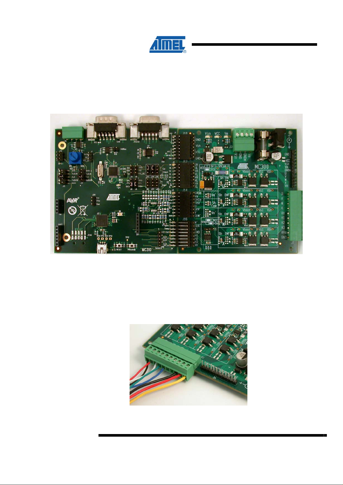
The two boards must be connected as shown in Figure 2-1.
Figure 2-1. Power up the kit
3 Connecting the BLDC motor
The motor must be connected as shown in the Figure 3-1.
Figure 3-1. Connecting the BLDC motor
2
AVR471
8181A-AVR-11/08
4 Powering the kit
Table 3-1. Signals
J7 signals Motor wires
U Thick yellow
V Thick red
W Thick black
X Not connected
Vn Not connected
H1 Thin blue
H2 Thin green
H3 Thin white
VHa Thin red
GND Thin black
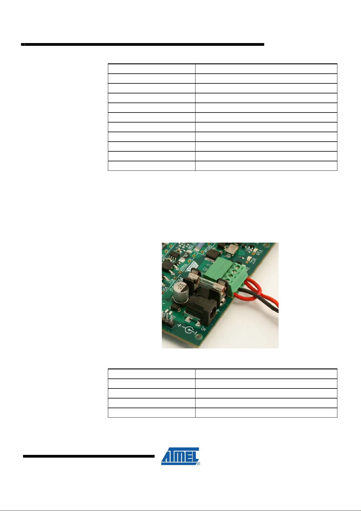
The kit must be powered using J3 connector as shown Figure 3-1:
AVR471
Figure 4-1. Powering the kit
Table 4-1. Signals
J3 signals Power wires
Vin Thick red (power)
GND Not Connected
GNDm Thick black (Ground)
Vm Thick red (power)
8181A-AVR-11/08
3

Take care to connect Vin (Board supply) to Vm (Motor supply) together.
When powering using J5 jack connector, take care of the polarity as shown on the
silk-screen.
Electrical characteristics:
• Vin: 10 – 20VDC coming from the Power board
• Im
min
= 2A
5 Default jumpers configuration
The following jumpers must be configured as below:
• J5, J6, J8, J9 : 2-3 jumper closed
• J21, J23, J25 : 1-2 jumper closed (Vn motor filtered)
• J22, J24, J26 : 1-2 jumper closed (Hall sensors 1, 2, 3)
• J12, J13 : 7-8 jumper closed (RxUSB, TxUSB selected)
• J7 : open (RxCAN)
• J15 : open (CAN Res)
• J28 : 1-2 jumper closed (Vcc-UVcc)
6 Default demo
The MC320 kit is delivered already programmed with a sensor motor control demo.
The potentiometer is used to control the motor speed.
Using the USB cable included in the kit with the Atmel Motor Control Center PC
software, the user can drive the motor from the PC interface.
4
Note:
After connecting the USB cable between a PC & the MC320 kit, a new device
detection wizard will appear, point the wizard to the .inf file at90usbxxx_cdc.inf
available on the MC320 kit Atmel web page. Check that your device is enumerated as
a COM port (see picture below).Then you can use the USB interface of MC320 kit as
a Virtual COM Port.
AVR471
8181A-AVR-11/08

Figure 4-1. Device manager
AVR471
Atmel Control Center is available for free on Atmel Web site:
http://www.atmel.com/dyn/products/tools_card.asp?tool_id=4170
8181A-AVR-11/08
5
 Loading...