


Instruction Set Nomenclature
Status Register (SREG)
SREG: Status Register
C: Carry Flag
Z: Zero Flag
N: Negative Flag
V: Two’s complement overflow indicator
S: N ⊕ V, For signed tests
H: Half Carry Flag
T: Transfer bit used by BLD and BST instructions
I: Global Interrupt Enable/Disable Flag
Registers and Operands
Rd: Destination (and source) register in the Register File
Rr: Source register in the Register File
R: Result after instruction is executed
K: Constant data
k: Constant address
b: Bit in the Register File or I/O Register (3-bit)
s: Bit in the Status Register (3-bit)
X,Y,Z: Indirect Address Register
(X=R27:R26, Y=R29:R28 and Z=R31:R30)
8-bit
Instruction Set
A: I/O location address
q: Displacement for direct addressing (6-bit)
Rev. 0856I–AVR–07/10

I/O Registers
RAMPX, RAMPY, RAMPZ
Registers concatenated with the X-, Y-, and Z-registers enabling indirect addressing of the whole data space on MCUs with
more than 64K bytes data space, and constant data fetch on MCUs with more than 64K bytes program space.
RAMPD
Register concatenated with the Z-register enabling direct addressing of the whole data space on MCUs with more than 64K
bytes data space.
EIND
Register concatenated with the Z-register enabling indirect jump and call to the whole program space on MCUs with more
than 64K words (128K bytes) program space.
Stack
STACK: Stack for return address and pushed registers
SP: Stack Pointer to STACK
Flags
⇔: Flag affected by instruction
0: Flag cleared by instruction
1: Flag set by instruction
-: Flag not affected by instruction
2
AVR Instruction Set
0856I–AVR–07/10
AVR Instruction Set
The Program and Data Addressing Modes
The AVR Enhanced RISC microcontroller supports powerful and efficient addressing modes for access to the Program
memory (Flash) and Data memory (SRAM, Register file, I/O Memory, and Extended I/O Memory). This section describes
the various addressing modes supported by the AVR architecture. In the following figures, OP means the operation code
part of the instruction word. To simplify, not all figures show the exact location of the addressing bits. To generalize, the
abstract terms RAMEND and FLASHEND have been used to represent the highest location in data and program space,
respectively.
Note: Not all addressing modes are present in all devices. Refer to the device spesific instruction summary.
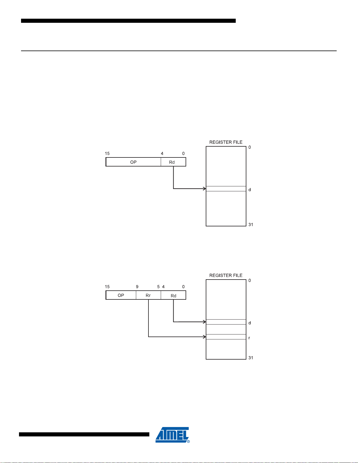
Register Direct, Single Register Rd
Figure 1. Direct Single Register Addressing
The operand is contained in register d (Rd).
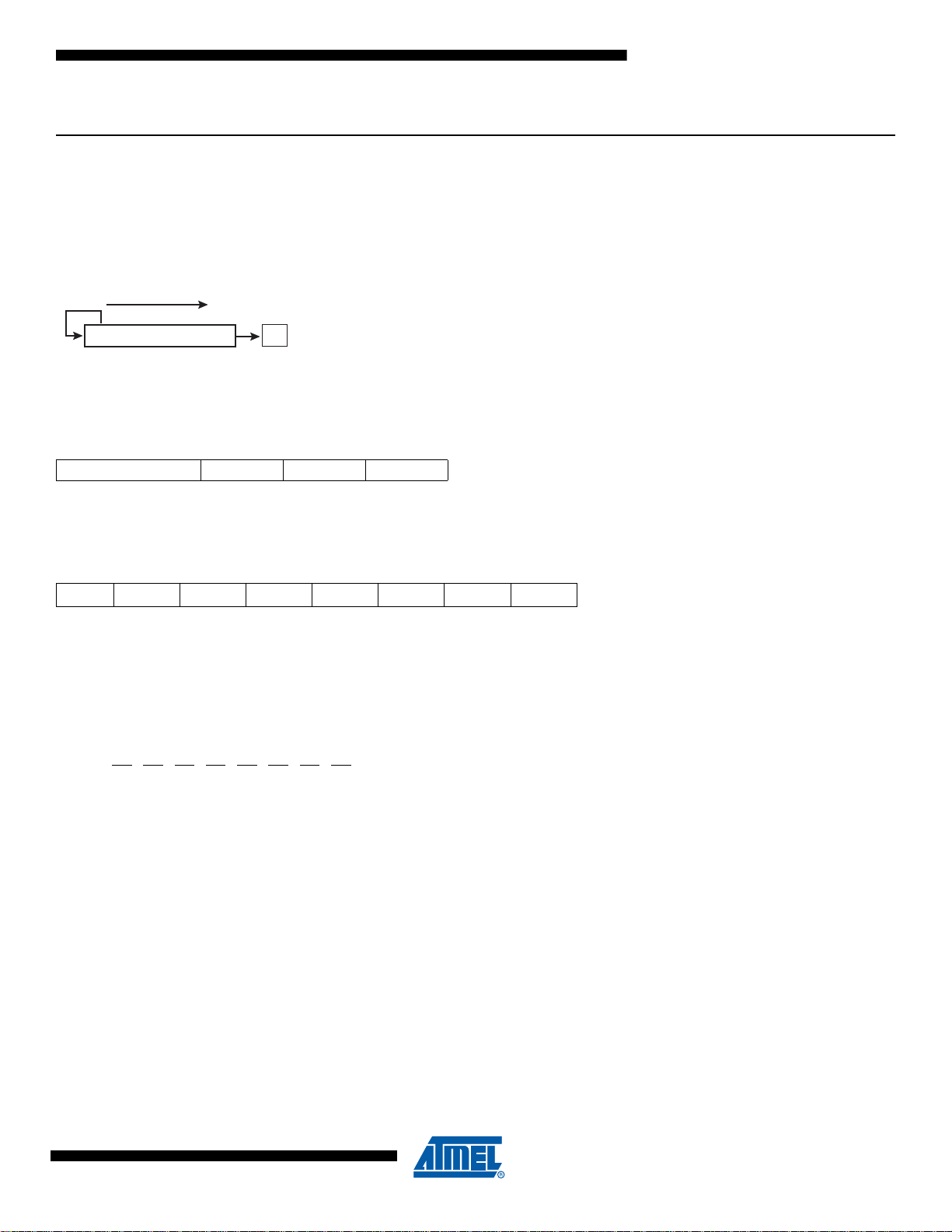
Register Direct, Two Registers Rd and Rr
Figure 2. Direct Register Addressing, Two Registers
Operands are contained in register r (Rr) and d (Rd). The result is stored in register d (Rd).
0856I–AVR–07/10
3
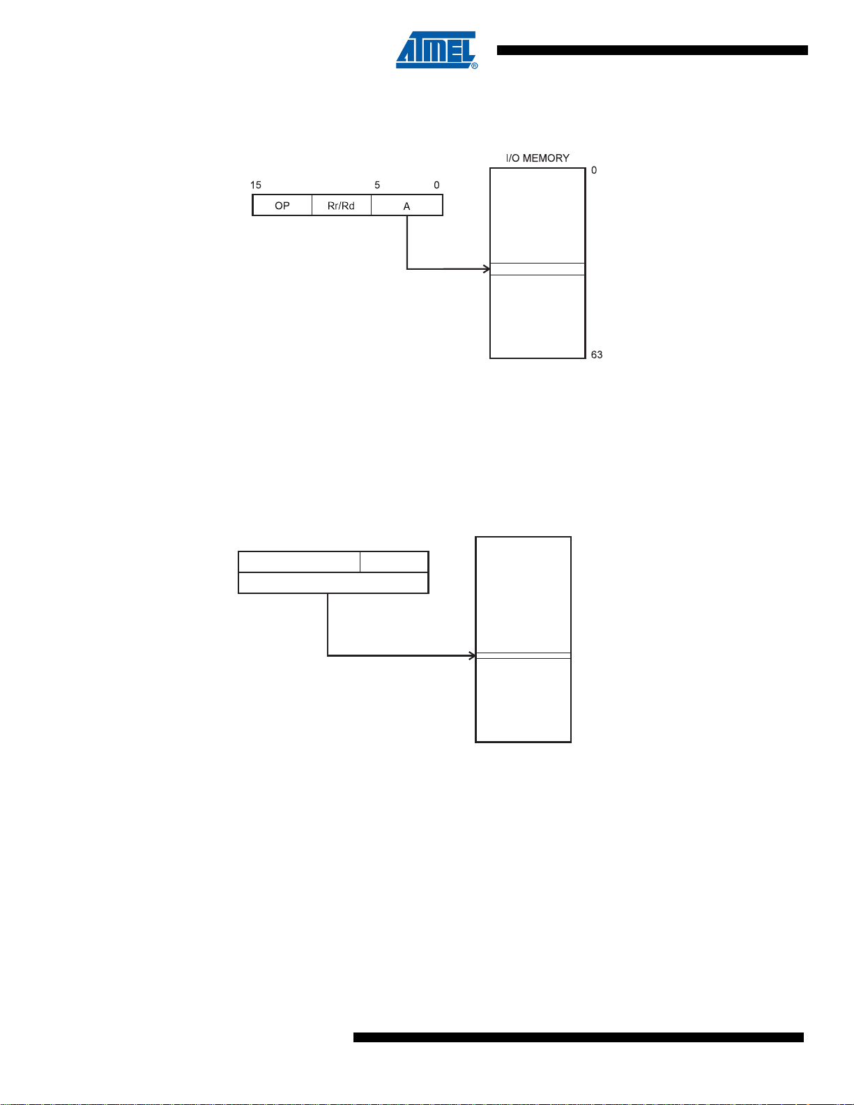
I/O Direct
OP Rr/Rd
16
31
15 0
Data Address
0x0000
RAMEND
20 19
Data Space
Figure 3. I/O Direct Addressing
Operand address is contained in 6 bits of the instruction word. n is the destination or source register address.
Note: Some complex AVR Microcontrollers have more peripheral units than can be supported within the 64 locations reserved in the
opcode for I/O direct addressing. The extended I/O memory from address 64 to 255 can only be reached by data addressing,
not I/O addressing.
Data Direct
Figure 4. Direct Data Addressing
A 16-bit Data Address is contained in the 16 LSBs of a two-word instruction. Rd/Rr specify the destination or source
register.
4
AVR Instruction Set
0856I–AVR–07/10
AVR Instruction Set
Data Space
0x0000
RAMEND
Y OR Z - REGISTER
OP qRr/Rd
0
05610
15
15
Data Space
0x0000
X, Y OR Z - REGISTER
015
RAMEND
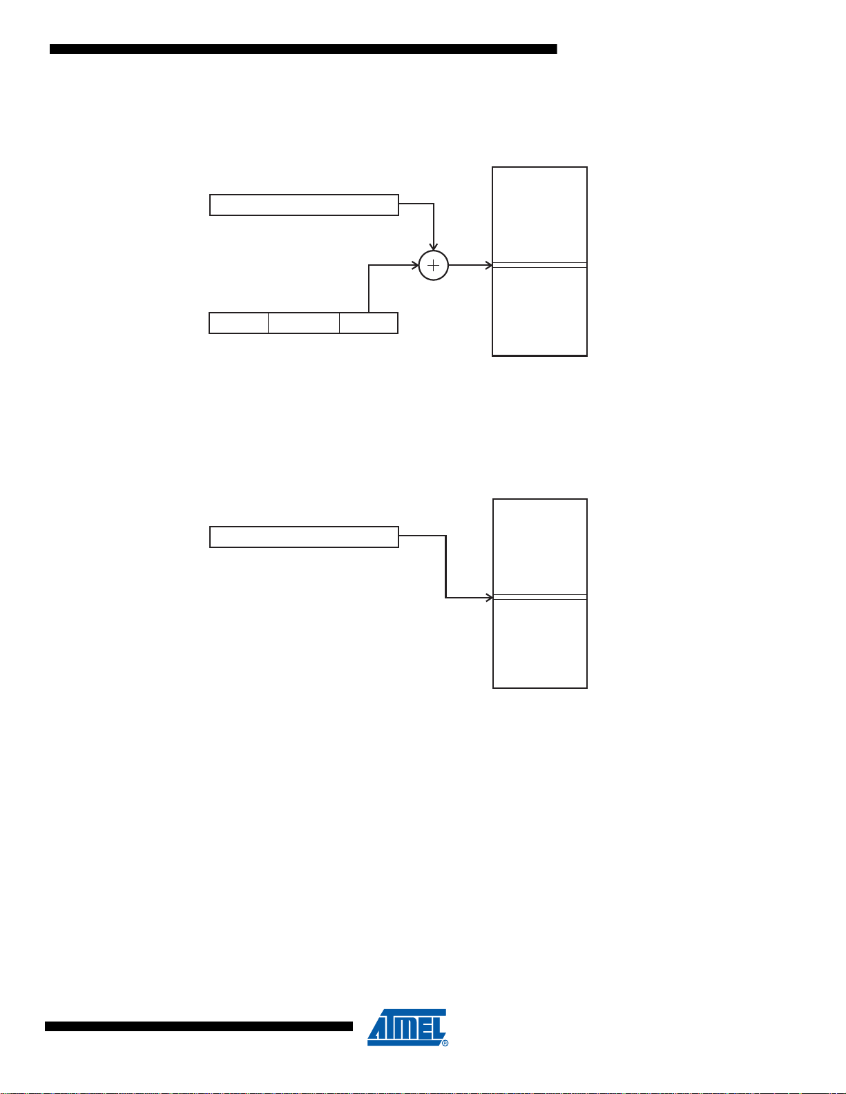
Data Indirect with Displacement
Figure 5. Data Indirect with Displacement
Operand address is the result of the Y- or Z-register contents added to the address contained in 6 bits of the instruction
word. Rd/Rr specify the destination or source register.
Data Indirect
Figure 6. Data Indirect Addressing
Operand address is the contents of the X-, Y-, or the Z-register. In AVR devices without SRAM, Data Indirect Addressing is
called Register Indirect Addressing. Register Indirect Addressing is a subset of Data Indirect Addressing since the data
space form 0 to 31 is the Register File.
0856I–AVR–07/10
5
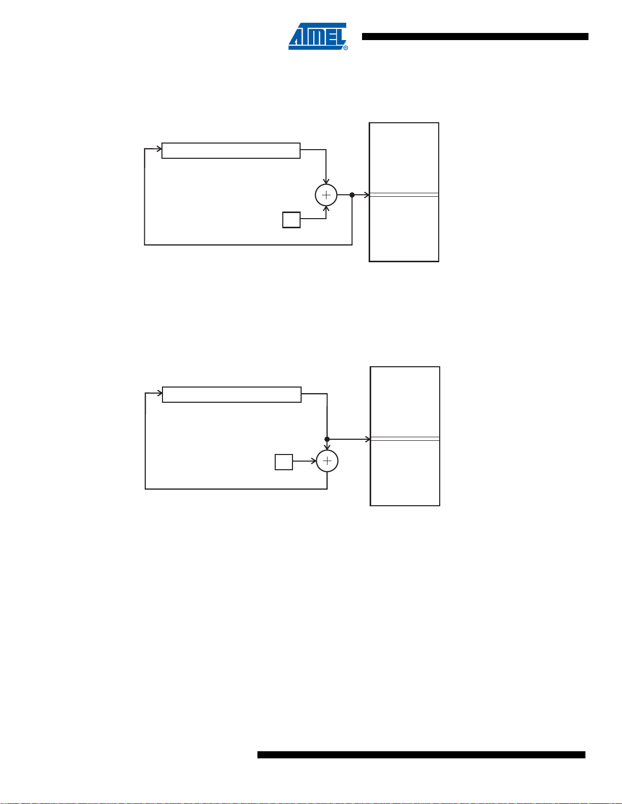
Data Indirect with Pre-decrement
Data Space
0x0000
X, Y OR Z - REGISTER
015
-1
RAMEND
Data Space
0x0000
X, Y OR Z - REGISTER
015
1
RAMEND
Figure 7. Data Indirect Addressing with Pre-decrement
The X,- Y-, or the Z-register is decremented before the operation. Operand address is the decremented contents of the X-,
Y-, or the Z-register.
Data Indirect with Post-increment
Figure 8. Data Indirect Addressing with Post-increment
The X-, Y-, or the Z-register is incremented after the operation. Operand address is the content of the X-, Y-, or the Z-register prior to incrementing.
6
AVR Instruction Set
0856I–AVR–07/10
AVR Instruction Set
FLASHEND
0x0000
LSB
FLASHEND
0x0000
1
LSB
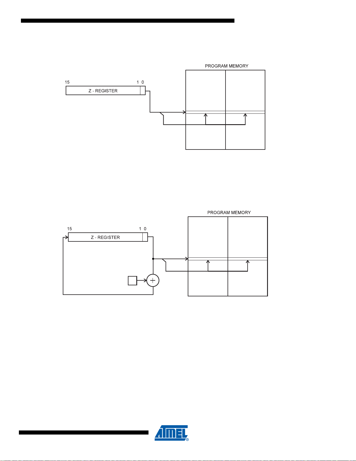
Program Memory Constant Addressing using the LPM, ELPM, and SPM Instructions
Figure 9. Program Memory Constant Addressing
Constant byte address is specified by the Z-register contents. The 15 MSBs select word address. For LPM, the LSB selects
low byte if cleared (LSB = 0) or high byte if set (LSB = 1). For SPM, the LSB should be cleared. If ELPM is used, the
RAMPZ Register is used to extend the Z-register.
Program Memory with Post-increment using the LPM Z+ and ELPM Z+ Instruction
Figure 10. Program Memory Addressing with Post-increment
Constant byte address is specified by the Z-register contents. The 15 MSBs select word address. The LSB selects low byte
if cleared (LSB = 0) or high byte if set (LSB = 1). If ELPM Z+ is used, the RAMPZ Register is used to extend the Z-register.
0856I–AVR–07/10
7
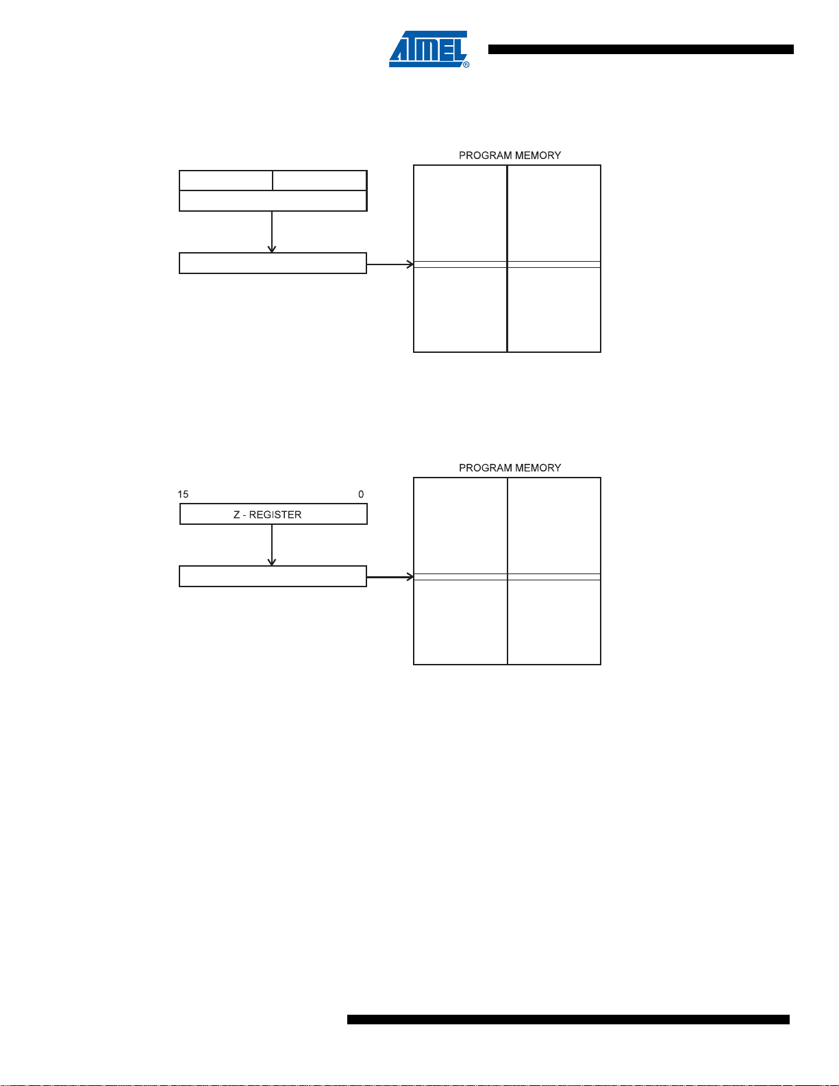
Direct Program Addressing, JMP and CALL
FLASHEND
31 16
OP 6 MSB
16 LSB
PC
21 0
15 0
0x0000
FLASHEND
PC
15 0
0x0000
Figure 11. Direct Program Memory Addressing
Program execution continues at the address immediate in the instruction word.
Indirect Program Addressing, IJMP and ICALL
Figure 12. Indirect Program Memory Addressing
Program execution continues at address contained by the Z-register (i.e., the PC is loaded with the contents of the Zregister).
8
AVR Instruction Set
0856I–AVR–07/10
AVR Instruction Set
FLASHEND
1
0x0000
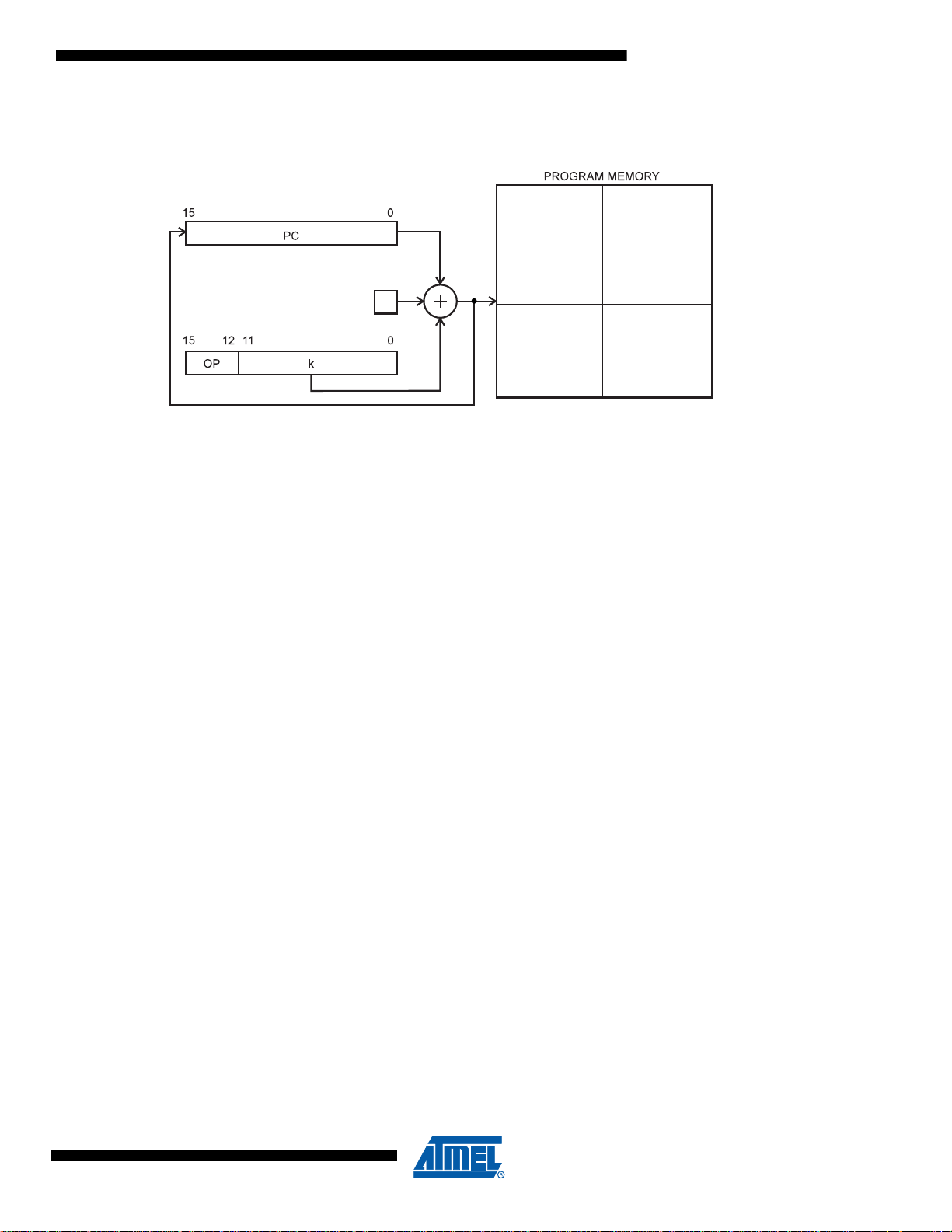
Relative Program Addressing, RJMP and RCALL
Figure 13. Relative Program Memory Addressing
Program execution continues at address PC + k + 1. The relative address k is from -2048 to 2047.
0856I–AVR–07/10
9

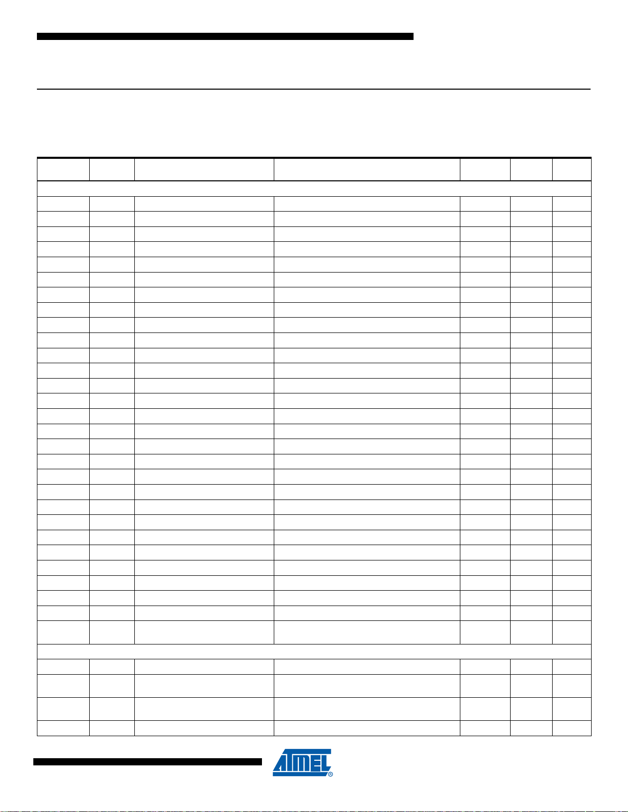
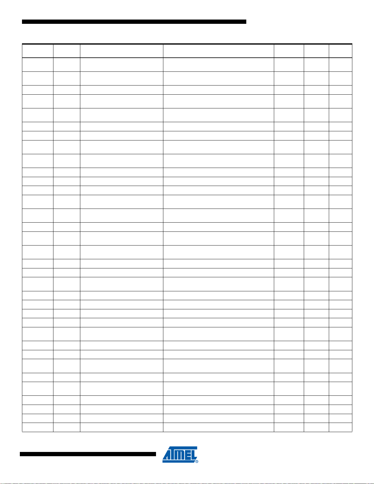
Conditional Branch Summary
Test Boolean Mnemonic Complementary Boolean Mnemonic Comment
Rd > Rr Z•(N ⊕ V) = 0 BRLT
Rd Rr (N ⊕ V) = 0 BRGE Rd < Rr (N ⊕ V) = 1 BRLT Signed
Rd = Rr Z = 1 BREQ Rd ≠ Rr Z = 0 BRNE Signed
Rd ≤ Rr Z+(N ⊕ V) = 1 BRGE
Rd < Rr (N ⊕ V) = 1 BRLT Rd ≥ Rr (N ⊕ V) = 0 BRGE Signed
Rd > Rr C + Z = 0 BRLO
Rd Rr C = 0 BRSH/BRCC Rd < Rr C = 1 BRLO/BRCS Unsigned
Rd = Rr Z = 1 BREQ Rd ≠ Rr Z = 0 BRNE Unsigned
Rd ≤ Rr C + Z = 1 BRSH
Rd < Rr C = 1 BRLO/BRCS Rd ≥ Rr C = 0 BRSH/BRCC Unsigned
Carry C = 1 BRCS No carry C = 0 BRCC Simple
Negative N = 1 BRMI Positive N = 0 BRPL Simple
Overflow V = 1 BRVS No overflow V = 0 BRVC Simple
Zero Z = 1 BREQ Not zero Z = 0 BRNE Simple
Note: 1. Interchange Rd and Rr in the operation before the test, i.e., CP Rd,Rr → CP Rr,Rd
(1)
(1)
(1)
(1)
Rd ≤ Rr Z+(N ⊕ V) = 1 BRGE* Signed
Rd > Rr Z•(N ⊕ V) = 0 BRLT* Signed
Rd ≤ Rr C + Z = 1 BRSH* Unsigned
Rd > Rr C + Z = 0 BRLO* Unsigned
10
AVR Instruction Set
0856I–AVR–07/10
Complete Instruction Set Summary
Instruction Set Summary
AVR Instruction Set
Mnemonics Operands Description Operation Flags #Clocks
Arithmetic and Logic Instructions
ADD Rd, Rr Add without Carry Rd ← Rd + Rr Z,C,N,V,S,H 1
ADC Rd, Rr Add with Carry Rd ← Rd + Rr + C Z,C,N,V,S,H 1
(1)
ADIW
SUB Rd, Rr Subtract without Carry Rd ← Rd - Rr Z,C,N,V,S,H 1
SUBI Rd, K Subtract Immediate Rd ← Rd - K Z,C,N,V,S,H 1
SBC Rd, Rr Subtract with Carry Rd ← Rd - Rr - C Z,C,N,V,S,H 1
SBCI Rd, K Subtract Immediate with Carry Rd ← Rd - K - C Z,C,N,V,S,H 1
(1)
SBIW
AND Rd, Rr Logical AND Rd ← Rd • Rr Z,N,V,S 1
ANDI Rd, K Logical AND with Immediate Rd ← Rd • K Z,N,V,S 1
OR Rd, Rr Logical OR Rd ← Rd v Rr Z,N,V,S 1
ORI Rd, K Logical OR with Immediate Rd ← Rd v K Z,N,V,S 1
EOR Rd, Rr Exclusive OR Rd ← Rd ⊕ Rr Z,N,V,S 1
COM Rd One’s Complement Rd ← $FF - Rd Z,C,N,V,S 1
NEG Rd Two’s Complement Rd ← $00 - Rd Z,C,N,V,S,H 1
SBR Rd,K Set Bit(s) in Register Rd ← Rd v K Z,N,V,S 1
CBR Rd,K Clear Bit(s) in Register Rd ← Rd • ($FFh - K) Z,N,V,S 1
INC Rd Increment Rd ← Rd + 1 Z,N,V,S 1
DEC Rd Decrement Rd ← Rd - 1 Z,N,V,S 1
TST Rd Test for Zero or Minus Rd ← Rd • Rd Z,N,V,S 1
CLR Rd Clear Register Rd ← Rd ⊕ Rd Z,N,V,S 1
SER Rd Set Register Rd ← $FF None 1
(1)
MUL
(1)
MULS
MULSU
(1)
FMUL
FMULS
FMULSU
DES K Data Encryption if (H = 0) then R15:R0
RJMP k Relative Jump PC ← PC + k + 1 None 2
(1)
IJMP
(1)
EIJMP
(1)
JMP
Rd, K Add Immediate to Word Rd ← Rd + 1:Rd + K Z,C,N,V,S 2
Rd, K Subtract Immediate from Word Rd + 1:Rd ← Rd + 1:Rd - K Z,C,N,V,S 2
Rd,Rr Multiply Unsigned R1:R0 ← Rd x Rr (UU) Z,C 2
Rd,Rr Multiply Signed R1:R0 ← Rd x Rr (SS) Z,C 2
(1)
Rd,Rr Multiply Signed with Unsigned R1:R0 ← Rd x Rr (SU) Z,C 2
Rd,Rr Fractional Multiply Unsigned R1:R0 ← Rd x Rr<<1 (UU) Z,C 2
(1)
Rd,Rr Fractional Multiply Signed R1:R0 ← Rd x Rr<<1 (SS) Z,C 2
(1)
Rd,Rr Fractional Multiply Signed with Unsigned R1:R0 ← Rd x Rr<<1 (SU) Z,C 2
else if (H = 1) then R15:R0←←
Branch Instructions
Indirect Jump to (Z) PC(15:0)
Extended Indirect Jump to (Z) PC(15:0)
kJump PC← kNone3
PC(21:16)←←Z,0
PC(21:16)←←Z,EIND
Encrypt(R15:R0, K)
Decrypt(R15:R0, K)
None 2
None 2
#Clocks
XMEGA
1/2
0856I–AVR–07/10
11

(3)(5)
(3)
(3)
(3)
(3)
#Clocks
XMEGA
(3)
2 / 3
(3)
2 / 3
(3)
3
(3)
3 / 4
Mnemonics Operands Description Operation Flags #Clocks
RCALL k Relative Call Subroutine PC ← PC + k + 1 None 3 / 4
(1)
ICALL
EICALL
CALL
(1)
(1)
k call Subroutine PC ← kNone4 / 5
Indirect Call to (Z) PC(15:0)
Extended Indirect Call to (Z) PC(15:0)
PC(21:16)←←Z,0
PC(21:16)←←Z,EIND
None 3 / 4
None 4
(3)
RET Subroutine Return PC ← STACK None 4 / 5
RETI Interrupt Return PC ← STACK I 4 / 5
CPSE Rd,Rr Compare, Skip if Equal if (Rd = Rr) PC ← PC + 2 or 3 None 1 / 2 / 3
CP Rd,Rr Compare Rd - Rr Z,C,N,V,S,H 1
CPC Rd,Rr Compare with Carry Rd - Rr - C Z,C,N,V,S,H 1
CPI Rd,K Compare with Immediate Rd - K Z,C,N,V,S,H 1
SBRC Rr, b Skip if Bit in Register Cleared if (Rr(b) = 0) PC ← PC + 2 or 3 None 1 / 2 / 3
SBRS Rr, b Skip if Bit in Register Set if (Rr(b) = 1) PC ← PC + 2 or 3 None 1 / 2 / 3
SBIC A, b Skip if Bit in I/O Register Cleared if (I/O(A,b) = 0) PC ← PC + 2 or 3 None 1 / 2 / 3 2 / 3 / 4
SBIS A, b Skip if Bit in I/O Register Set If (I/O(A,b) =1) PC ← PC + 2 or 3 None 1 / 2 / 3 2 / 3 / 4
BRBS s, k Branch if Status Flag Set if (SREG(s) = 1) then PC ← PC + k + 1 None 1 / 2
BRBC s, k Branch if Status Flag Cleared if (SREG(s) = 0) then PC ← PC + k + 1 None 1 / 2
BREQ k Branch if Equal if (Z = 1) then PC ← PC + k + 1 None 1 / 2
BRNE k Branch if Not Equal if (Z = 0) then PC ← PC + k + 1 None 1 / 2
BRCS k Branch if Carry Set if (C = 1) then PC ← PC + k + 1 None 1 / 2
BRCC k Branch if Carry Cleared if (C = 0) then PC ← PC + k + 1 None 1 / 2
BRSH k Branch if Same or Higher if (C = 0) then PC ← PC + k + 1 None 1 / 2
BRLO k Branch if Lower if (C = 1) then PC ← PC + k + 1 None 1 / 2
BRMI k Branch if Minus if (N = 1) then PC ← PC + k + 1 None 1 / 2
BRPL k Branch if Plus if (N = 0) then PC ← PC + k + 1 None 1 / 2
BRGE k Branch if Greater or Equal, Signed if (N ⊕ V= 0) then PC ← PC + k + 1 None 1 / 2
BRLT k Branch if Less Than, Signed if (N ⊕ V= 1) then PC ← PC + k + 1 None 1 / 2
BRHS k Branch if Half Carry Flag Set if (H = 1) then PC ← PC + k + 1 None 1 / 2
BRHC k Branch if Half Carry Flag Cleared if (H = 0) then PC ← PC + k + 1 None 1 / 2
BRTS k Branch if T Flag Set if (T = 1) then PC ← PC + k + 1 None 1 / 2
BRTC k Branch if T Flag Cleared if (T = 0) then PC ← PC + k + 1 None 1 / 2
BRVS k Branch if Overflow Flag is Set if (V = 1) then PC ← PC + k + 1 None 1 / 2
BRVC k Branch if Overflow Flag is Cleared if (V = 0) then PC ← PC + k + 1 None 1 / 2
BRIE k Branch if Interrupt Enabled if (I = 1) then PC ← PC + k + 1 None 1 / 2
BRID k Branch if Interrupt Disabled if (I = 0) then PC ← PC + k + 1 None 1 / 2
Data Transfer Instructions
MOV Rd, Rr Copy Register Rd ← Rr None 1
(1)
MOVW
Rd, Rr Copy Register Pair Rd+1:Rd ← Rr+1:Rr None 1
LDI Rd, K Load Immediate Rd ← KNone1
LDS
LD
(1)
(2)
Rd, k Load Direct from data space Rd ← (k) None 1
Rd, X Load Indirect Rd ← (X) None 1
(5)/2(3)
(5)2(3)
(3)(4)
2
(3)(4)
1
12
AVR Instruction Set
0856I–AVR–07/10
AVR Instruction Set
Mnemonics Operands Description Operation Flags #Clocks
(2)
LD
(2)
LD
(2)
LD
(2)
LD
(2)
LD
LDD
(2)
LD
(2)
LD
(2)
LD
LDD
STS
(2)
ST
(2)
ST
(2)
ST
(2)
ST
(2)
ST
(2)
ST
STD
(2)
ST
(2)
ST
(2)
ST
STD
LPM
LPM
LPM
ELPM
ELPM
ELPM
SPM
SPM
(1)
(1)
(1)
(1)
(1)
(1)(2)
(1)(2)
(1)(2)
(1)
(1)
Rd, X+ Load Indirect and Post-Increment RdX←←(X)
Rd, -X Load Indirect and Pre-Decrement X ← X - 1,
Rd ← (X)←←
X + 1
X - 1
(X)
None 2
None 2
Rd, Y Load Indirect Rd ← (Y) ← (Y) None 1
Rd, Y+ Load Indirect and Post-Increment RdY←←(Y)
Rd, -Y Load Indirect and Pre-Decrement YRd←←Y - 1
Y + 1
(Y)
None 2
None 2
Rd, Y+q Load Indirect with Displacement Rd ← (Y + q) None 2
Rd, Z Load Indirect Rd ← (Z) None 1
Rd, Z+ Load Indirect and Post-Increment RdZ←←(Z),
Rd, -Z Load Indirect and Pre-Decrement ZRd←←Z - 1,
Z+1
(Z)
None 2
None 2
Rd, Z+q Load Indirect with Displacement Rd ← (Z + q) None 2
k, Rr Store Direct to Data Space (k) ← Rd None 1
X, Rr Store Indirect (X) ← Rr None 1
X+, Rr Store Indirect and Post-Increment (X)X←←Rr,
-X, Rr Store Indirect and Pre-Decrement X
(X)←←
X + 1
X - 1,
Rr
None 1
None 2
Y, Rr Store Indirect (Y) ← Rr None 1
Y+, Rr Store Indirect and Post-Increment (Y)Y←←Rr,
-Y, Rr Store Indirect and Pre-Decrement Y
(Y)←←
Y + 1
Y - 1,
Rr
None 1
None 2
Y+q, Rr Store Indirect with Displacement (Y + q) ← Rr None 2
Z, Rr Store Indirect (Z) ← Rr None 1
Z+, Rr Store Indirect and Post-Increment (Z)Z←←Rr
Z + 1
None 1
-Z, Rr Store Indirect and Pre-Decrement Z ← Z - 1 None 2
Z+q,Rr Store Indirect with Displacement (Z + q) ← Rr None 2
Load Program Memory R0 ← (Z) None 3 3
Rd, Z Load Program Memory Rd ← (Z) None 3 3
Rd, Z+ Load Program Memory and Post-
(1)
(1)
(1)
Rd, Z Extended Load Program Memory Rd ← (RAMPZ:Z) None 3
Rd, Z+ Extended Load Program Memory and
Increment
Extended Load Program Memory R0 ← (RAMPZ:Z) None 3
Post-Increment
RdZ←←(Z),
RdZ←←(RAMPZ:Z),
Z + 1
Z + 1
None 3 3
None 3
Store Program Memory (RAMPZ:Z) ← R1:R0 None - -
Z+ Store Program Memory and Post-
Increment by 2
(RAMPZ:Z)Z←←R1:R0,
Z + 2
None - -
(3)
(3)/3(5)
(5)/2(3)
(3)
(3)/3(5)
(3)
(5)/2(3)
(3)
(3)/3(5)
(3)
(5)/2(3)
(5)/2(3)
(5)/2(3)
(3)
(5)/2(3)
(5)/2(3)
(3)
(3)
(5)/2(3)
(5)/2(3)
(3)
(3)
IN Rd, A In From I/O Location Rd ← I/O(A) None 1
OUT A, Rr Out To I/O Location I/O(A) ← Rr None 1
(1)
PUSH
POP
(1)
Rr Push Register on Stack STACK ← Rr None 2 1
Rd Pop Register from Stack Rd ← STACK None 2 2
#Clocks
XMEGA
(3)(4)
1
(3)(4)
2
(3)(4)
1
(3)(4)
1
(3)(4)
2
(3)(4)
2
(3)(4)
1
(3)(4)
1
(3)(4)
2
(3)(4)
2
(3)
2
(3)
1
(3)
1
(3)
2
(3)
1
(3)
1
(3)
2
(3)
2
(3)
1
(3)
1
(3)
2
(3)
2
(3)
(3)
0856I–AVR–07/10
13

Mnemonics Operands Description Operation Flags #Clocks
XCH Z, Rd Exchange (Z)Rd←←Rd,
LAS Z, Rd Load and Set (Z)Rd←←Rd v (Z)
LAC Z, Rd Load and Clear (Z)Rd←←($FF – Rd) • (Z)
LAT Z, Rd Load and Toggle (Z)Rd←←Rd ⊕ (Z)
Bit and Bit-test Instructions
LSL Rd Logical Shift Left Rd(n+1)
LSR Rd Logical Shift Right Rd(n)
ROL Rd Rotate Left Through Carry Rd(0)
ROR Rd Rotate Right Through Carry Rd(7)
ASR Rd Arithmetic Shift Right Rd(n) ← Rd(n+1), n=0..6 Z,C,N,V 1
SWAP Rd Swap Nibbles Rd(3..0) ↔ Rd(7..4) None 1
BSET s Flag Set SREG(s) ← 1SREG(s)1
BCLR s Flag Clear SREG(s) ← 0SREG(s)1
SBI A, b Set Bit in I/O Register I/O(A, b) ← 1None1
CBI A, b Clear Bit in I/O Register I/O(A, b) ← 0None1
BST Rr, b Bit Store from Register to T T ← Rr(b) T 1
BLD Rd, b Bit load from T to Register Rd(b) ← TNone1
SEC Set Carry C ← 1C1
CLC Clear Carry C ← 0C1
SEN Set Negative Flag N ← 1N1
CLN Clear Negative Flag N ← 0N1
SEZ Set Zero Flag Z ← 1Z1
CLZ Clear Zero Flag Z ← 0Z1
SEI Global Interrupt Enable I ← 1I1
CLI Global Interrupt Disable I ← 0I1
SES Set Signed Test Flag S ← 1S1
CLS Clear Signed Test Flag S ← 0S1
SEV Set Two’s Complement Overflow V ← 1V1
CLV Clear Two’s Complement Overflow V ← 0V1
SET Set T in SREG T ← 1T1
CLT Clear T in SREG T ← 0T1
SEH Set Half Carry Flag in SREG H ← 1H1
CLH Clear Half Carry Flag in SREG H ← 0H1
MCU Control Instructions
(1)
BREAK
Break (See specific descr. for BREAK) None 1
Rd(0)
Rd(7)
Rd(n+1)
Rd(n)
C
C
C
C
←
←
←
←
←
←
←
←
←
←
←
←
(Z)
(Z)
(Z)
(Z)
Rd(n),
0,
Rd(7)
Rd(n+1),
0,
Rd(0)
C,
Rd(n),
Rd(7)
C,
Rd(n+1),
Rd(0)
None 1
None 1
None 1
None 1
Z,C,N,V,H 1
Z,C,N,V 1
Z,C,N,V,H 1
Z,C,N,V 1
(5)
21
(5)
/2 1
#Clocks
XMEGA
14
AVR Instruction Set
0856I–AVR–07/10

AVR Instruction Set
Mnemonics Operands Description Operation Flags #Clocks
NOP No Operation None 1
SLEEP Sleep (see specific descr. for Sleep) None 1
WDR Watchdog Reset (see specific descr. for WDR) None 1
Notes: 1. This instruction is not available in all devices. Refer to the device specific instruction set summary.
2. Not all variants of this instruction are available in all devices. Refer to the device specific instruction set summary.
3. Cycle times for Data memory accesses assume internal memory accesses, and are not valid for accesses via the external
RAM interface.
4. One extra cycle must be added when accessing Internal SRAM.
5. Number of clock cycles for Reduced Core tinyAVR.
#Clocks
XMEGA
0856I–AVR–07/10
15

ADC – Add with Carry
Description:
Adds two registers and the contents of the C Flag and places the result in the destination register Rd.
Operation:
(i) Rd ← Rd + Rr + C
Syntax: Operands: Program Counter:
(i) ADC Rd,Rr 0 ≤ d ≤ 31, 0 ≤ r ≤ 31 PC ← PC + 1
16-bit Opcode:
0001 11rd dddd rrrr
Status Register (SREG) Boolean Formula:
ITHSVNZC
––⇔⇔⇔⇔⇔⇔
H: Rd3•Rr3+Rr3•R3
+R3•Rd3
Set if there was a carry from bit 3; cleared otherwise
S: N ⊕ V, For signed tests.
V: Rd7•Rr7•R7
+Rd7•Rr7•R7
Set if two’s complement overflow resulted from the operation; cleared otherwise.
N: R7
Set if MSB of the result is set; cleared otherwise.
Z: R7
• R6 •R5• R4 •R3 •R2 •R1 •R0
Set if the result is $00; cleared otherwise.
C: Rd7•Rr7+Rr7•R7
+R7•Rd7
Set if there was carry from the MSB of the result; cleared otherwise.
R (Result) equals Rd after the operation.
Example:
; Add R1:R0 to R3:R2
add r2,r0 ; Add low byte
adc r3,r1 ; Add with carry high byte
Words: 1 (2 bytes)
Cycles: 1
16
AVR Instruction Set
0856I–AVR–07/10

AVR Instruction Set
ADD – Add without Carry
Description:
Adds two registers without the C Flag and places the result in the destination register Rd.
Operation:
(i) Rd ← Rd + Rr
Syntax: Operands: Program Counter:
(i) ADD Rd,Rr 0 ≤ d ≤ 31, 0 ≤ r ≤ 31 PC ← PC + 1
16-bit Opcode:
0000 11rd dddd rrrr
Status Register (SREG) and Boolean Formula:
ITHSVNZC
––⇔⇔⇔⇔⇔⇔
H: Rd3•Rr3+Rr3•R3
+R3•Rd3
Set if there was a carry from bit 3; cleared otherwise
S: N ⊕ V, For signed tests.
V: Rd7•Rr7•R7
+Rd7•Rr7•R7
Set if two’s complement overflow resulted from the operation; cleared otherwise.
N: R7
Set if MSB of the result is set; cleared otherwise.
Z: R7
• R6 •R5• R4 •R3 •R2 •R1 •R0
Set if the result is $00; cleared otherwise.
C: Rd7 •Rr7 +Rr7 •R7
+ R7 •Rd7
Set if there was carry from the MSB of the result; cleared otherwise.
R (Result) equals Rd after the operation.
Example:
add r1,r2 ; Add r2 to r1 (r1=r1+r2)
add r28,r28 ; Add r28 to itself (r28=r28+r28)
Words: 1 (2 bytes)
Cycles: 1
0856I–AVR–07/10
17

ADIW – Add Immediate to Word
Description:
Adds an immediate value (0 - 63) to a register pair and places the result in the register pair. This instruction operates on the
upper four register pairs, and is well suited for operations on the pointer registers.
This instruction is not available in all devices. Refer to the device specific instruction set summary.
Operation:
(i) Rd+1:Rd ← Rd+1:Rd + K
Syntax: Operands: Program Counter:
(i) ADIW Rd+1:Rd,K d ∈ {24,26,28,30}, 0 ≤ K ≤ 63 PC ← PC + 1
16-bit Opcode:
1001 0110 KKdd KKKK
Status Register (SREG) and Boolean Formula:
ITHSVNZC
–– –⇔⇔⇔⇔⇔
S: N ⊕ V, For signed tests.
V: Rdh7
• R15
Set if two’s complement overflow resulted from the operation; cleared otherwise.
N: R15
Set if MSB of the result is set; cleared otherwise.
Z: R15
•R14 •R13 •R12 •R11 •R10 •R9 •R8 •R7• R6• R5• R4• R3• R2 •R1• R0
Set if the result is $0000; cleared otherwise.
C: R15
• Rdh7
Set if there was carry from the MSB of the result; cleared otherwise.
R (Result) equals Rdh:Rdl after the operation (Rdh7-Rdh0 = R15-R8, Rdl7-Rdl0=R7-R0).
Example:
adiw r25:24,1 ; Add 1 to r25:r24
adiw ZH:ZL,63 ; Add 63 to the Z-pointer(r31:r30)
Words: 1 (2 bytes)
Cycles: 2
18
AVR Instruction Set
0856I–AVR–07/10
AVR Instruction Set
AND – Logical AND
Description:
Performs the logical AND between the contents of register Rd and register Rr and places the result in the destination register Rd.
Operation:
(i) Rd ← Rd • Rr
Syntax: Operands: Program Counter:
(i) AND Rd,Rr 0 ≤ d ≤ 31, 0 ≤ r ≤ 31 PC ← PC + 1
16-bit Opcode:
0010 00rd dddd rrrr
Status Register (SREG) and Boolean Formula:
ITHSVNZC
–– –⇔ 0 ⇔⇔ –
S: N ⊕ V, For signed tests.
V: 0
Cleared
N: R7
Set if MSB of the result is set; cleared otherwise.
Z: R7
•R6 •R5 •R4 •R3• R2 •R1 •R0
Set if the result is $00; cleared otherwise.
R (Result) equals Rd after the operation.
Example:
and r2,r3 ; Bitwise and r2 and r3, result in r2
ldi r16,1 ; Set bitmask 0000 0001 in r16
and r2,r16 ; Isolate bit 0 in r2
Words: 1 (2 bytes)
Cycles: 1
0856I–AVR–07/10
19

ANDI – Logical AND with Immediate
Description:
Performs the logical AND between the contents of register Rd and a constant and places the result in the destination register Rd.
Operation:
(i) Rd ← Rd • K
Syntax: Operands: Program Counter:
(i) ANDI Rd,K 16 ≤ d ≤ 31, 0 ≤ K ≤ 255 PC ← PC + 1
16-bit Opcode:
0111 KKKK dddd KKKK
Status Register (SREG) and Boolean Formula:
ITHSVNZC
–– –⇔
0
⇔⇔ –
S: N ⊕ V, For signed tests.
V: 0
Cleared
N: R7
Set if MSB of the result is set; cleared otherwise.
Z: R7
•R6• R5•R4 •R3• R2• R1• R0
Set if the result is $00; cleared otherwise.
R (Result) equals Rd after the operation.
Example:
andi r17,$0F ; Clear upper nibble of r17
andi r18,$10 ; Isolate bit 4 in r18
andi r19,$AA ; Clear odd bits of r19
Words: 1 (2 bytes)
Cycles: 1
20
AVR Instruction Set
0856I–AVR–07/10
AVR Instruction Set
b7-------------------b0 C
ASR – Arithmetic Shift Right
Description:
Shifts all bits in Rd one place to the right. Bit 7 is held constant. Bit 0 is loaded into the C Flag of the SREG. This operation
effectively divides a signed value by two without changing its sign. The Carry Flag can be used to round the result.
Operation:
(i)
Syntax: Operands: Program Counter:
(i) ASR Rd 0 ≤ d ≤ 31 PC ← PC + 1
16-bit Opcode:
1001 010d dddd 0101
Status Register (SREG) and Boolean Formula:
ITHSVNZC
–– –⇔⇔⇔⇔⇔
S: N ⊕ V, For signed tests.
V: N ⊕ C (For N and C after the shift)
N: R7
Set if MSB of the result is set; cleared otherwise.
Z: R7
•R6 •R5• R4 •R3 •R2• R1• R0
Set if the result is $00; cleared otherwise.
C: Rd0
Set if, before the shift, the LSB of Rd was set; cleared otherwise.
R (Result) equals Rd after the operation.
Example:
ldi r16,$10 ; Load decimal 16 into r16
asr r16 ; r16=r16 / 2
ldi r17,$FC ; Load -4 in r17
asr r17 ; r17=r17/2
Words: 1 (2 bytes)
Cycles: 1
0856I–AVR–07/10
21
BCLR – Bit Clear in SREG
Description:
Clears a single Flag in SREG.
Operation:
(i) SREG(s) ← 0
Syntax: Operands: Program Counter:
(i) BCLR s 0 ≤ s ≤ 7PC ← PC + 1
16-bit Opcode:
1001 0100 1sss 1000
Status Register (SREG) and Boolean Formula:
ITHSVNZC
⇔⇔⇔⇔⇔⇔⇔⇔
I: 0 if s = 7; Unchanged otherwise.
T: 0 if s = 6; Unchanged otherwise.
H: 0 if s = 5; Unchanged otherwise.
S: 0 if s = 4; Unchanged otherwise.
V: 0 if s = 3; Unchanged otherwise.
N: 0 if s = 2; Unchanged otherwise.
Z: 0 if s = 1; Unchanged otherwise.
C: 0 if s = 0; Unchanged otherwise.
Example:
bclr 0 ; Clear Carry Flag
bclr 7 ; Disable interrupts
Words: 1 (2 bytes)
Cycles: 1
22
AVR Instruction Set
0856I–AVR–07/10
AVR Instruction Set
BLD – Bit Load from the T Flag in SREG to a Bit in Register
Description:
Copies the T Flag in the SREG (Status Register) to bit b in register Rd.
Operation:
(i) Rd(b) ← T
Syntax: Operands: Program Counter:
(i) BLD Rd,b 0 ≤ d ≤ 31, 0 ≤ b ≤ 7PC ← PC + 1
16 bit Opcode:
1111 100d dddd 0bbb
Status Register (SREG) and Boolean Formula:
ITHSVNZC
––––––––
Example:
; Copy bit
bst r1,2 ; Store bit 2 of r1 in T Flag
bld r0,4 ; Load T Flag into bit 4 of r0
Words: 1 (2 bytes)
Cycles: 1
0856I–AVR–07/10
23

BRBC – Branch if Bit in SREG is Cleared
Description:
Conditional relative branch. Tests a single bit in SREG and branches relatively to PC if the bit is cleared. This instruction
branches relatively to PC in either direction (PC - 63 ≤ destination ≤ PC + 64). The parameter k is the offset from PC and is
represented in two’s complement form.
Operation:
(i) If SREG(s) = 0 then PC ← PC + k + 1, else PC ← PC + 1
Syntax: Operands: Program Counter:
(i) BRBC s,k 0 ≤ s ≤ 7, -64 ≤ k ≤ +63 PC ← PC + k + 1
PC ← PC + 1, if condition is false
16-bit Opcode:
1111 01kk kkkk ksss
Status Register (SREG) and Boolean Formula:
ITHSVNZC
––––––––
Example:
cpi r20,5 ; Compare r20 to the value 5
brbc 1,noteq ; Branch if Zero Flag cleared
...
noteq:nop ; Branch destination (do nothing)
Words: 1 (2 bytes)
Cycles: 1 if condition is false
2 if condition is true
24
AVR Instruction Set
0856I–AVR–07/10
AVR Instruction Set
BRBS – Branch if Bit in SREG is Set
Description:
Conditional relative branch. Tests a single bit in SREG and branches relatively to PC if the bit is set. This instruction
branches relatively to PC in either direction (PC - 63 ≤ destination ≤ PC + 64). The parameter k is the offset from PC and is
represented in two’s complement form.
Operation:
(i) If SREG(s) = 1 then PC ← PC + k + 1, else PC ← PC + 1
Syntax: Operands: Program Counter:
(i) BRBS s,k 0 ≤ s ≤ 7, -64 ≤ k ≤ +63 PC ← PC + k + 1
PC ← PC + 1, if condition is false
16-bit Opcode:
1111 00kk kkkk ksss
Status Register (SREG) and Boolean Formula:
ITHSVNZC
––––––––
Example:
bst r0,3 ; Load T bit with bit 3 of r0
brbs 6,bitset ; Branch T bit was set
...
bitset: nop ; Branch destination (do nothing)
Words: 1 (2 bytes)
Cycles: 1 if condition is false
2 if condition is true
0856I–AVR–07/10
25

BRCC – Branch if Carry Cleared
Description:
Conditional relative branch. Tests the Carry Flag (C) and branches relatively to PC if C is cleared. This instruction branches
relatively to PC in either direction (PC - 63 ≤ destination ≤ PC + 64). The parameter k is the offset from PC and is represented in two’s complement form. (Equivalent to instruction BRBC 0,k).
Operation:
(i) If C = 0 then PC ← PC + k + 1, else PC ← PC + 1
Syntax: Operands: Program Counter:
(i) BRCC k -64 ≤ k ≤ +63 PC ← PC + k + 1
PC ← PC + 1, if condition is false
16-bit Opcode:
1111 01kk kkkk k000
Status Register (SREG) and Boolean Formula:
ITHSVNZC
––––––––
Example:
add r22,r23 ; Add r23 to r22
brcc nocarry ; Branch if carry cleared
...
nocarry: nop ; Branch destination (do nothing)
Words: 1 (2 bytes)
Cycles: 1 if condition is false
2 if condition is true
26
AVR Instruction Set
0856I–AVR–07/10

AVR Instruction Set
BRCS – Branch if Carry Set
Description:
Conditional relative branch. Tests the Carry Flag (C) and branches relatively to PC if C is set. This instruction branches relatively to PC in either direction (PC - 63 ≤ destination ≤ PC + 64). The parameter k is the offset from PC and is represented
in two’s complement form. (Equivalent to instruction BRBS 0,k).
Operation:
(i) If C = 1 then PC ← PC + k + 1, else PC ← PC + 1
Syntax: Operands: Program Counter:
(i) BRCS k -64 ≤ k ≤ +63 PC ← PC + k + 1
PC ← PC + 1, if condition is false
16-bit Opcode:
1111 00kk kkkk k000
Status Register (SREG) and Boolean Formula:
ITHSVNZC
––––––––
Example:
cpi r26,$56 ; Compare r26 with $56
brcs carry ; Branch if carry set
...
carry: nop ; Branch destination (do nothing)
Words: 1 (2 bytes)
Cycles: 1 if condition is false
2 if condition is true
0856I–AVR–07/10
27

BREAK – Break
Description:
The BREAK instruction is used by the On-chip Debug system, and is normally not used in the application software. When
the BREAK instruction is executed, the AVR CPU is set in the Stopped Mode. This gives the On-chip Debugger access to
internal resources.
If any Lock bits are set, or either the JTAGEN or OCDEN Fuses are unprogrammed, the CPU will treat the BREAK instruction as a NOP and will not enter the Stopped mode.
This instruction is not available in all devices. Refer to the device specific instruction set summary.
Operation:
(i) On-chip Debug system break.
Syntax: Operands: Program Counter:
(i) BREAK None PC ← PC + 1
16-bit Opcode:
1001 0101 1001 1000
Status Register (SREG) and Boolean Formula:
ITHSVNZC
––––––––
Words: 1 (2 bytes)
Cycles: 1
28
AVR Instruction Set
0856I–AVR–07/10

AVR Instruction Set
BREQ – Branch if Equal
Description:
Conditional relative branch. Tests the Zero Flag (Z) and branches relatively to PC if Z is set. If the instruction is executed
immediately after any of the instructions CP, CPI, SUB or SUBI, the branch will occur if and only if the unsigned or signed
binary number represented in Rd was equal to the unsigned or signed binary number represented in Rr. This instruction
branches relatively to PC in either direction (PC - 63 ≤ destination ≤ PC + 64). The parameter k is the offset from PC and is
represented in two’s complement form. (Equivalent to instruction BRBS 1,k).
Operation:
(i) If Rd = Rr (Z = 1) then PC ← PC + k + 1, else PC ← PC + 1
Syntax: Operands: Program Counter:
(i) BREQ k -64 ≤ k ≤ +63 PC ← PC + k + 1
PC ← PC + 1, if condition is false
16-bit Opcode:
1111 00kk kkkk k001
Status Register (SREG) and Boolean Formula:
ITHSVNZC
––––––––
Example:
cp r1,r0 ; Compare registers r1 and r0
breq equal ; Branch if registers equal
...
equal: nop ; Branch destination (do nothing)
Words: 1 (2 bytes)
Cycles: 1 if condition is false
2 if condition is true
0856I–AVR–07/10
29
BRGE – Branch if Greater or Equal (Signed)
Description:
Conditional relative branch. Tests the Signed Flag (S) and branches relatively to PC if S is cleared. If the instruction is executed immediately after any of the instructions CP, CPI, SUB or SUBI, the branch will occur if and only if the signed binary
number represented in Rd was greater than or equal to the signed binary number represented in Rr. This instruction
branches relatively to PC in either direction (PC - 63 ≤ destination ≤ PC + 64). The parameter k is the offset from PC and is
represented in two’s complement form. (Equivalent to instruction BRBC 4,k).
Operation:
(i) If Rd ≥ Rr (N ⊕ V = 0) then PC ← PC + k + 1, else PC ← PC + 1
Syntax: Operands: Program Counter:
(i) BRGE k -64 ≤ k ≤ +63 PC ← PC + k + 1
PC ← PC + 1, if condition is false
16-bit Opcode:
1111 01kk kkkk k100
Status Register (SREG) and Boolean Formula:
ITHSVNZC
––––––––
Example:
cp r11,r12 ; Compare registers r11 and r12
brge greateq ; Branch if r11 ≥ r12 (signed)
...
greateq: nop ; Branch destination (do nothing)
Words: 1 (2 bytes)
Cycles: 1 if condition is false
2 if condition is true
30
AVR Instruction Set
0856I–AVR–07/10

AVR Instruction Set
BRHC – Branch if Half Carry Flag is Cleared
Description:
Conditional relative branch. Tests the Half Carry Flag (H) and branches relatively to PC if H is cleared. This instruction
branches relatively to PC in either direction (PC - 63 ≤ destination ≤ PC + 64). The parameter k is the offset from PC and is
represented in two’s complement form. (Equivalent to instruction BRBC 5,k).
Operation:
(i) If H = 0 then PC ← PC + k + 1, else PC ← PC + 1
Syntax: Operands: Program Counter:
(i) BRHC k -64 ≤ k ≤ +63 PC ← PC + k + 1
PC ← PC + 1, if condition is false
16-bit Opcode:
1111 01kk kkkk k101
Status Register (SREG) and Boolean Formula:
ITHSVNZC
––––––––
Example:
brhc hclear ; Branch if Half Carry Flag cleared
...
hclear: nop ; Branch destination (do nothing)
Words: 1 (2 bytes)
Cycles: 1 if condition is false
2 if condition is true
0856I–AVR–07/10
31

BRHS – Branch if Half Carry Flag is Set
Description:
Conditional relative branch. Tests the Half Carry Flag (H) and branches relatively to PC if H is set. This instruction branches
relatively to PC in either direction (PC - 63 ≤ destination ≤ PC + 64). The parameter k is the offset from PC and is represented in two’s complement form. (Equivalent to instruction BRBS 5,k).
Operation:
(i) If H = 1 then PC ← PC + k + 1, else PC ← PC + 1
Syntax: Operands: Program Counter:
(i) BRHS k -64 ≤ k ≤ +63 PC ← PC + k + 1
PC ← PC + 1, if condition is false
16-bit Opcode:
1111 00kk kkkk k101
Status Register (SREG) and Boolean Formula:
ITHSVNZC
––––––––
Example:
brhs hset ; Branch if Half Carry Flag set
...
hset: nop ; Branch destination (do nothing)
Words: 1 (2 bytes)
Cycles: 1 if condition is false
2 if condition is true
32
AVR Instruction Set
0856I–AVR–07/10

AVR Instruction Set
BRID – Branch if Global Interrupt is Disabled
Description:
Conditional relative branch. Tests the Global Interrupt Flag (I) and branches relatively to PC if I is cleared. This instruction
branches relatively to PC in either direction (PC - 63 ≤ destination ≤ PC + 64). The parameter k is the offset from PC and is
represented in two’s complement form. (Equivalent to instruction BRBC 7,k).
Operation:
(i) If I = 0 then PC ← PC + k + 1, else PC ← PC + 1
Syntax: Operands: Program Counter:
(i) BRID k -64 ≤ k ≤ +63 PC ← PC + k + 1
PC ← PC + 1, if condition is false
16-bit Opcode:
1111 01kk kkkk k111
Status Register (SREG) and Boolean Formula:
ITHSVNZC
––––––––
Example:
brid intdis ; Branch if interrupt disabled
...
intdis: nop ; Branch destination (do nothing)
Words: 1 (2 bytes)
Cycles: 1 if condition is false
2 if condition is true
0856I–AVR–07/10
33

BRIE – Branch if Global Interrupt is Enabled
Description:
Conditional relative branch. Tests the Global Interrupt Flag (I) and branches relatively to PC if I is set. This instruction
branches relatively to PC in either direction (PC - 63 ≤ destination ≤ PC + 64). The parameter k is the offset from PC and is
represented in two’s complement form. (Equivalent to instruction BRBS 7,k).
Operation:
(i) If I = 1 then PC ← PC + k + 1, else PC ← PC + 1
Syntax: Operands: Program Counter:
(i) BRIE k -64 ≤ k ≤ +63 PC ← PC + k + 1
PC ← PC + 1, if condition is false
16-bit Opcode:
1111 00kk kkkk k111
Status Register (SREG) and Boolean Formula:
ITHSVNZC
––––––––
Example:
brie inten ; Branch if interrupt enabled
...
inten: nop ; Branch destination (do nothing)
Words: 1 (2 bytes)
Cycles: 1 if condition is false
2 if condition is true
34
AVR Instruction Set
0856I–AVR–07/10

AVR Instruction Set
BRLO – Branch if Lower (Unsigned)
Description:
Conditional relative branch. Tests the Carry Flag (C) and branches relatively to PC if C is set. If the instruction is executed
immediately after any of the instructions CP, CPI, SUB or SUBI, the branch will occur if and only if the unsigned binary
number represented in Rd was smaller than the unsigned binary number represented in Rr. This instruction branches relatively to PC in either direction (PC - 63 ≤ destination ≤ PC + 64). The parameter k is the offset from PC and is represented
in two’s complement form. (Equivalent to instruction BRBS 0,k).
Operation:
(i) If Rd < Rr (C = 1) then PC ← PC + k + 1, else PC ← PC + 1
Syntax: Operands: Program Counter:
(i) BRLO k -64 ≤ k ≤ +63 PC ← PC + k + 1
PC ← PC + 1, if condition is false
16-bit Opcode:
1111 00kk kkkk k000
Status Register (SREG) and Boolean Formula:
ITHSVNZC
––––––––
Example:
eor r19,r19 ; Clear r19
loop: inc r19 ; Increase r19
...
cpi r19,$10 ; Compare r19 with $10
brlo loop ; Branch if r19 < $10 (unsigned)
nop ; Exit from loop (do nothing)
Words: 1 (2 bytes)
Cycles: 1 if condition is false
2 if condition is true
0856I–AVR–07/10
35

BRLT – Branch if Less Than (Signed)
Description:
Conditional relative branch. Tests the Signed Flag (S) and branches relatively to PC if S is set. If the instruction is executed
immediately after any of the instructions CP, CPI, SUB or SUBI, the branch will occur if and only if the signed binary number represented in Rd was less than the signed binary number represented in Rr. This instruction branches relatively to PC
in either direction (PC - 63 ≤ destination ≤ PC + 64). The parameter k is the offset from PC and is represented in two’s complement form. (Equivalent to instruction BRBS 4,k).
Operation:
(i) If Rd < Rr (N ⊕ V = 1) then PC ← PC + k + 1, else PC ← PC + 1
Syntax: Operands: Program Counter:
(i) BRLT k -64 ≤ k ≤ +63 PC ← PC + k + 1
PC ← PC + 1, if condition is false
16-bit Opcode:
1111 00kk kkkk k100
Status Register (SREG) and Boolean Formula:
ITHSVNZC
––––––––
Example:
cp r16,r1 ; Compare r16 to r1
brlt less ; Branch if r16 < r1 (signed)
...
less: nop ; Branch destination (do nothing)
Words: 1 (2 bytes)
Cycles: 1 if condition is false
2 if condition is true
36
AVR Instruction Set
0856I–AVR–07/10

AVR Instruction Set
BRMI – Branch if Minus
Description:
Conditional relative branch. Tests the Negative Flag (N) and branches relatively to PC if N is set. This instruction branches
relatively to PC in either direction (PC - 63 ≤ destination ≤ PC + 64). The parameter k is the offset from PC and is represented in two’s complement form. (Equivalent to instruction BRBS 2,k).
Operation:
(i) If N = 1 then PC ← PC + k + 1, else PC ← PC + 1
Syntax: Operands: Program Counter:
(i) BRMI k -64 ≤ k ≤ +63 PC ← PC + k + 1
PC ← PC + 1, if condition is false
16-bit Opcode:
1111 00kk kkkk k010
Status Register (SREG) and Boolean Formula:
ITHSVNZC
––––––––
Example:
subi r18,4 ; Subtract 4 from r18
brmi negative ; Branch if result negative
...
negative: nop ; Branch destination (do nothing)
Words: 1 (2 bytes)
Cycles: 1 if condition is false
2 if condition is true
0856I–AVR–07/10
37

BRNE – Branch if Not Equal
Description:
Conditional relative branch. Tests the Zero Flag (Z) and branches relatively to PC if Z is cleared. If the instruction is executed immediately after any of the instructions CP, CPI, SUB or SUBI, the branch will occur if and only if the unsigned or
signed binary number represented in Rd was not equal to the unsigned or signed binary number represented in Rr. This
instruction branches relatively to PC in either direction (PC - 63 ≤ destination ≤ PC + 64). The parameter k is the offset from
PC and is represented in two’s complement form. (Equivalent to instruction BRBC 1,k).
Operation:
(i) If Rd ≠ Rr (Z = 0) then PC ← PC + k + 1, else PC ← PC + 1
Syntax: Operands: Program Counter:
(i) BRNE k -64 ≤ k ≤ +63 PC ← PC + k + 1
PC ← PC + 1, if condition is false
16-bit Opcode:
1111 01kk kkkk k001
Status Register (SREG) and Boolean Formula:
ITHSVNZC
––––––––
Example:
eor r27,r27 ; Clear r27
loop: inc r27 ; Increase r27
...
cpi r27,5 ; Compare r27 to 5
brne loop ; Branch if r27<>5
nop ; Loop exit (do nothing)
Words: 1 (2 bytes)
Cycles: 1 if condition is false
2 if condition is true
38
AVR Instruction Set
0856I–AVR–07/10

AVR Instruction Set
BRPL – Branch if Plus
Description:
Conditional relative branch. Tests the Negative Flag (N) and branches relatively to PC if N is cleared. This instruction
branches relatively to PC in either direction (PC - 63 ≤ destination ≤ PC + 64). The parameter k is the offset from PC and is
represented in two’s complement form. (Equivalent to instruction BRBC 2,k).
Operation:
(i) If N = 0 then PC ← PC + k + 1, else PC ← PC + 1
Syntax: Operands: Program Counter:
(i) BRPL k -64 ≤ k ≤ +63 PC ← PC + k + 1
PC ← PC + 1, if condition is false
16-bit Opcode:
1111 01kk kkkk k010
Status Register (SREG) and Boolean Formula:
ITHSVNZC
––––––––
Example:
subi r26,$50 ; Subtract $50 from r26
brpl positive ; Branch if r26 positive
...
positive: nop ; Branch destination (do nothing)
Words: 1 (2 bytes)
Cycles: 1 if condition is false
2 if condition is true
0856I–AVR–07/10
39

BRSH – Branch if Same or Higher (Unsigned)
Description:
Conditional relative branch. Tests the Carry Flag (C) and branches relatively to PC if C is cleared. If the instruction is executed immediately after execution of any of the instructions CP, CPI, SUB or SUBI the branch will occur if and only if the
unsigned binary number represented in Rd was greater than or equal to the unsigned binary number represented in Rr.
This instruction branches relatively to PC in either direction (PC - 63 ≤ destination ≤ PC + 64). The parameter k is the offset
from PC and is represented in two’s complement form. (Equivalent to instruction BRBC 0,k).
Operation:
(i) If Rd ≥Rr (C = 0) then PC ← PC + k + 1, else PC ← PC + 1
Syntax: Operands: Program Counter:
(i) BRSH k -64 ≤ k ≤ +63 PC ← PC + k + 1
PC ← PC + 1, if condition is false
16-bit Opcode:
1111 01kk kkkk k000
Status Register (SREG) and Boolean Formula:
ITHSVNZC
––––––––
Example:
subi r19,4 ; Subtract 4 from r19
brsh highsm ; Branch if r19 >= 4 (unsigned)
...
highsm: nop ; Branch destination (do nothing)
Words: 1 (2 bytes)
Cycles: 1 if condition is false
2 if condition is true
40
AVR Instruction Set
0856I–AVR–07/10

AVR Instruction Set
BRTC – Branch if the T Flag is Cleared
Description:
Conditional relative branch. Tests the T Flag and branches relatively to PC if T is cleared. This instruction branches relatively to PC in either direction (PC - 63 ≤ destination ≤ PC + 64). The parameter k is the offset from PC and is represented
in two’s complement form. (Equivalent to instruction BRBC 6,k).
Operation:
(i) If T = 0 then PC ← PC + k + 1, else PC ← PC + 1
Syntax: Operands: Program Counter:
(i) BRTC k -64 ≤ k ≤ +63 PC ← PC + k + 1
PC ← PC + 1, if condition is false
16-bit Opcode:
1111 01kk kkkk k110
Status Register (SREG) and Boolean Formula:
ITHSVNZC
––––––––
Example:
bst r3,5 ; Store bit 5 of r3 in T Flag
brtc tclear ; Branch if this bit was cleared
...
tclear: nop ; Branch destination (do nothing)
Words: 1 (2 bytes)
Cycles: 1 if condition is false
2 if condition is true
0856I–AVR–07/10
41

BRTS – Branch if the T Flag is Set
Description:
Conditional relative branch. Tests the T Flag and branches relatively to PC if T is set. This instruction branches relatively to
PC in either direction (PC - 63 ≤ destination ≤ PC + 64). The parameter k is the offset from PC and is represented in two’s
complement form. (Equivalent to instruction BRBS 6,k).
Operation:
(i) If T = 1 then PC ← PC + k + 1, else PC ← PC + 1
Syntax: Operands: Program Counter:
(i) BRTS k -64 ≤ k ≤ +63 PC ← PC + k + 1
PC ← PC + 1, if condition is false
16-bit Opcode:
1111 00kk kkkk k110
Status Register (SREG) and Boolean Formula:
ITHSVNZC
––––––––
Example:
bst r3,5 ; Store bit 5 of r3 in T Flag
brts tset ; Branch if this bit was set
...
tset: nop ; Branch destination (do nothing)
Words: 1 (2 bytes)
Cycles: 1 if condition is false
2 if condition is true
42
AVR Instruction Set
0856I–AVR–07/10

AVR Instruction Set
BRVC – Branch if Overflow Cleared
Description:
Conditional relative branch. Tests the Overflow Flag (V) and branches relatively to PC if V is cleared. This instruction branches relatively to PC in either direction (PC - 63 ≤ destination ≤ PC + 64). The parameter k is the offset from PC and is represented in two’s complement form. (Equivalent to instruction BRBC 3,k).
Operation:
(i) If V = 0 then PC ← PC + k + 1, else PC ← PC + 1
Syntax: Operands: Program Counter:
(i) BRVC k -64 ≤ k ≤ +63 PC ← PC + k + 1
PC ← PC + 1, if condition is false
16-bit Opcode:
1111 01kk kkkk k011
Status Register (SREG) and Boolean Formula:
ITHSVNZC
––––––––
Example:
add r3,r4 ; Add r4 to r3
brvc noover ; Branch if no overflow
...
noover: nop ; Branch destination (do nothing)
Words: 1 (2 bytes)
Cycles: 1 if condition is false
2 if condition is true
0856I–AVR–07/10
43

BRVS – Branch if Overflow Set
Description:
Conditional relative branch. Tests the Overflow Flag (V) and branches relatively to PC if V is set. This instruction branches
relatively to PC in either direction (PC - 63 ≤ destination ≤ PC + 64). The parameter k is the offset from PC and is represented in two’s complement form. (Equivalent to instruction BRBS 3,k).
Operation:
(i) If V = 1 then PC ← PC + k + 1, else PC ← PC + 1
Syntax: Operands: Program Counter:
(i) BRVS k -64 ≤ k ≤ +63 PC ← PC + k + 1
PC ← PC + 1, if condition is false
16-bit Opcode:
1111 00kk kkkk k011
Status Register (SREG) and Boolean Formula:
ITHSVNZC
––––––––
Example:
add r3,r4 ; Add r4 to r3
brvs overfl ; Branch if overflow
...
overfl: nop ; Branch destination (do nothing)
Words: 1 (2 bytes)
Cycles: 1 if condition is false
2 if condition is true
44
AVR Instruction Set
0856I–AVR–07/10

BSET – Bit Set in SREG
Description:
Sets a single Flag or bit in SREG.
Operation:
(i) SREG(s) ← 1
Syntax: Operands: Program Counter:
(i) BSET s 0 ≤ s ≤ 7PC ← PC + 1
16-bit Opcode:
1001 0100 0sss 1000
Status Register (SREG) and Boolean Formula:
ITHSVNZC
⇔⇔⇔⇔⇔⇔⇔⇔
AVR Instruction Set
I: 1 if s = 7; Unchanged otherwise.
T: 1 if s = 6; Unchanged otherwise.
H: 1 if s = 5; Unchanged otherwise.
S: 1 if s = 4; Unchanged otherwise.
V: 1 if s = 3; Unchanged otherwise.
N: 1 if s = 2; Unchanged otherwise.
Z: 1 if s = 1; Unchanged otherwise.
C: 1 if s = 0; Unchanged otherwise.
Example:
bset 6 ; Set T Flag
bset 7 ; Enable interrupt
Words: 1 (2 bytes)
Cycles: 1
0856I–AVR–07/10
45

BST – Bit Store from Bit in Register to T Flag in SREG
Description:
Stores bit b from Rd to the T Flag in SREG (Status Register).
Operation:
(i) T ← Rd(b)
Syntax: Operands: Program Counter:
(i) BST Rd,b 0 ≤ d ≤ 31, 0 ≤ b ≤ 7PC ← PC + 1
16-bit Opcode:
1111 101d dddd 0bbb
Status Register (SREG) and Boolean Formula:
ITHSVNZC
– ⇔ ––––––
T: 0 if bit b in Rd is cleared. Set to 1 otherwise.
Example:
; Copy bit
bst r1,2 ; Store bit 2 of r1 in T Flag
bld r0,4 ; Load T into bit 4 of r0
Words: 1 (2 bytes)
Cycles: 1
46
AVR Instruction Set
0856I–AVR–07/10

AVR Instruction Set
CALL – Long Call to a Subroutine
Description:
Calls to a subroutine within the entire Program memory. The return address (to the instruction after the CALL) will be stored
onto the Stack. (See also RCALL). The Stack Pointer uses a post-decrement scheme during CALL.
This instruction is not available in all devices. Refer to the device specific instruction set summary.
Operation:
(i) PC ← k Devices with 16 bits PC, 128K bytes Program memory maximum.
(ii) PC ← k Devices with 22 bits PC, 8M bytes Program memory maximum.
Syntax: Operands: Program Counter Stack:
(i) CALL k 0 ≤ k < 64K PC ← kSTACK ← PC+2
SP ← SP-2, (2 bytes, 16 bits)
(ii) CALL k 0 ≤ k < 4M PC ← kSTACK ← PC+2
SP ← SP-3 (3 bytes, 22 bits)
32-bit Opcode:
1001 010k kkkk 111k
kkkk kkkk kkkk kkkk
Status Register (SREG) and Boolean Formula:
ITHSVNZC
––––––––
Example:
mov r16,r0 ; Copy r0 to r16
call check ; Call subroutine
nop ; Continue (do nothing)
...
check: cpi r16,$42 ; Check if r16 has a special value
breq error ; Branch if equal
ret ; Return from subroutine
...
error: rjmp error ; Infinite loop
Words : 2 (4 bytes)
Cycles : 4, devices with 16 bit PC
5, devices with 22 bit PC
Cycles XMEGA: 3, devices with 16 bit PC
4, devices with 22 bit PC
0856I–AVR–07/10
47

CBI – Clear Bit in I/O Register
Description:
Clears a specified bit in an I/O Register. This instruction operates on the lower 32 I/O Registers – addresses 0-31.
Operation:
(i) I/O(A,b) ← 0
Syntax: Operands: Program Counter:
(i) CBI A,b 0 ≤ A ≤ 31, 0 ≤ b ≤ 7PC ← PC + 1
16-bit Opcode:
1001 1000 AAAA Abbb
Status Register (SREG) and Boolean Formula:
ITHSVNZC
––––––––
Example:
cbi $12,7 ; Clear bit 7 in Port D
Words : 1 (2 bytes)
Cycles : 2
Cycles XMEGA: 1
Cycles Reduced Core tinyAVR: 1
48
AVR Instruction Set
0856I–AVR–07/10

AVR Instruction Set
CBR – Clear Bits in Register
Description:
Clears the specified bits in register Rd. Performs the logical AND between the contents of register Rd and the complement
of the constant mask K. The result will be placed in register Rd.
Operation:
(i) Rd ← Rd • ($FF - K)
Syntax: Operands: Program Counter:
(i) CBR Rd,K 16 ≤ d ≤ 31, 0 ≤ K ≤ 255 PC ← PC + 1
16-bit Opcode: (see ANDI with K complemented)
Status Register (SREG) and Boolean Formula:
ITHSVNZC
–– –
⇔
0
⇔⇔ –
S: N ⊕ V, For signed tests.
V: 0
Cleared
N: R7
Set if MSB of the result is set; cleared otherwise.
Z: R7
•R6 •R5• R4• R3 •R2• R1• R0
Set if the result is $00; cleared otherwise.
R (Result) equals Rd after the operation.
Example:
cbr r16,$F0 ; Clear upper nibble of r16
cbr r18,1 ; Clear bit 0 in r18
Words: 1 (2 bytes)
Cycles: 1
0856I–AVR–07/10
49

CLC – Clear Carry Flag
Description:
Clears the Carry Flag (C) in SREG (Status Register).
Operation:
(i) C ← 0
Syntax: Operands: Program Counter:
(i) CLC None PC ← PC + 1
16-bit Opcode:
1001 0100 1000 1000
Status Register (SREG) and Boolean Formula:
ITHSVNZC
–––––––0
C: 0
Carry Flag cleared
Example:
add r0,r0 ; Add r0 to itself
clc ; Clear Carry Flag
Words: 1 (2 bytes)
Cycles: 1
50
AVR Instruction Set
0856I–AVR–07/10

CLH – Clear Half Carry Flag
Description:
Clears the Half Carry Flag (H) in SREG (Status Register).
Operation:
(i) H ← 0
Syntax: Operands: Program Counter:
(i) CLH None PC ← PC + 1
16-bit Opcode:
1001 0100 1101 1000
Status Register (SREG) and Boolean Formula:
ITHSVNZC
AVR Instruction Set
––0–––––
H: 0
Half Carry Flag cleared
Example:
clh ; Clear the Half Carry Flag
Words: 1 (2 bytes)
Cycles: 1
0856I–AVR–07/10
51

CLI – Clear Global Interrupt Flag
Description:
Clears the Global Interrupt Flag (I) in SREG (Status Register). The interrupts will be immediately disabled. No interrupt will
be executed after the CLI instruction, even if it occurs simultaneously with the CLI instruction.
Operation:
(i) I ← 0
Syntax: Operands: Program Counter:
(i) CLI None PC ← PC + 1
16-bit Opcode:
1001 0100 1111 1000
Status Register (SREG) and Boolean Formula:
ITHSVNZC
0–––––––
I: 0
Global Interrupt Flag cleared
Example:
in temp, SREG ; Store SREG value (temp must be defined by user)
cli ; Disable interrupts during timed sequence
sbi EECR, EEMWE ; Start EEPROM write
sbi EECR, EEWE
out SREG, temp ; Restore SREG value (I-Flag)
Words: 1 (2 bytes)
Cycles: 1
52
AVR Instruction Set
0856I–AVR–07/10

CLN – Clear Negative Flag
Description:
Clears the Negative Flag (N) in SREG (Status Register).
Operation:
(i) N ← 0
Syntax: Operands: Program Counter:
(i) CLN None PC ← PC + 1
16-bit Opcode:
1001 0100 1010 1000
Status Register (SREG) and Boolean Formula:
ITHSVNZC
AVR Instruction Set
–––––0––
N: 0
Negative Flag cleared
Example:
add r2,r3 ; Add r3 to r2
cln ; Clear Negative Flag
Words: 1 (2 bytes)
Cycles: 1
0856I–AVR–07/10
53

CLR – Clear Register
Description:
Clears a register. This instruction performs an Exclusive OR between a register and itself. This will clear all bits in the
register.
Operation:
(i) Rd ← Rd ⊕ Rd
Syntax: Operands: Program Counter:
(i) CLR Rd 0 ≤ d ≤ 31 PC ← PC + 1
16-bit Opcode: (see EOR Rd,Rd)
0010 01dd dddd dddd
Status Register (SREG) and Boolean Formula:
ITHSVNZC
–––0001–
S: 0
Cleared
V: 0
Cleared
N: 0
Cleared
Z: 1
Set
R (Result) equals Rd after the operation.
Example:
clr r18 ; clear r18
loop: inc r18 ; increase r18
...
cpi r18,$50 ; Compare r18 to $50
brne loop
Words: 1 (2 bytes)
Cycles: 1
54
AVR Instruction Set
0856I–AVR–07/10

CLS – Clear Signed Flag
Description:
Clears the Signed Flag (S) in SREG (Status Register).
Operation:
(i) S ← 0
Syntax: Operands: Program Counter:
(i) CLS None PC ← PC + 1
16-bit Opcode:
1001 0100 1100 1000
Status Register (SREG) and Boolean Formula:
ITHSVNZC
AVR Instruction Set
–––0––––
S: 0
Signed Flag cleared
Example:
add r2,r3 ; Add r3 to r2
cls ; Clear Signed Flag
Words: 1 (2 bytes)
Cycles: 1
0856I–AVR–07/10
55

CLT – Clear T Flag
Description:
Clears the T Flag in SREG (Status Register).
Operation:
(i) T ← 0
Syntax: Operands: Program Counter:
(i) CLT None PC ← PC + 1
16-bit Opcode:
1001 0100 1110 1000
Status Register (SREG) and Boolean Formula:
ITHSVNZC
–0––––––
T: 0
T Flag cleared
Example:
clt ; Clear T Flag
Words: 1 (2 bytes)
Cycles: 1
56
AVR Instruction Set
0856I–AVR–07/10

CLV – Clear Overflow Flag
Description:
Clears the Overflow Flag (V) in SREG (Status Register).
Operation:
(i) V ← 0
Syntax: Operands: Program Counter:
(i) CLV None PC ← PC + 1
16-bit Opcode:
1001 0100 1011 1000
Status Register (SREG) and Boolean Formula:
ITHSVNZC
AVR Instruction Set
––––0–––
V: 0
Overflow Flag cleared
Example:
add r2,r3 ; Add r3 to r2
clv ; Clear Overflow Flag
Words: 1 (2 bytes)
Cycles: 1
0856I–AVR–07/10
57

CLZ – Clear Zero Flag
Description:
Clears the Zero Flag (Z) in SREG (Status Register).
Operation:
(i) Z ← 0
Syntax: Operands: Program Counter:
(i) CLZ None PC ← PC + 1
16-bit Opcode:
1001 0100 1001 1000
Status Register (SREG) and Boolean Formula:
ITHSVNZC
––––––0–
Z: 0
Zero Flag cleared
Example:
add r2,r3 ; Add r3 to r2
clz ; Clear zero
Words: 1 (2 bytes)
Cycles: 1
58
AVR Instruction Set
0856I–AVR–07/10

COM – One’s Complement
Description:
This instruction performs a One’s Complement of register Rd.
Operation:
(i) Rd ← $FF - Rd
Syntax: Operands: Program Counter:
(i) COM Rd 0 ≤ d ≤ 31 PC ← PC + 1
16-bit Opcode:
1001 010d dddd 0000
Status Register (SREG) and Boolean Formula:
ITHSVNZC
–– –
⇔
0
⇔⇔
1
AVR Instruction Set
S: N ⊕ V
For signed tests.
V: 0
Cleared.
N: R7
Set if MSB of the result is set; cleared otherwise.
Z: R7
•R6• R5• R4 •R3 •R2• R1 •R0
Set if the result is $00; Cleared otherwise.
C: 1
Set.
R (Result) equals Rd after the operation.
Example:
com r4 ; Take one’s complement of r4
breq zero ; Branch if zero
...
zero: nop ; Branch destination (do nothing)
Words: 1 (2 bytes)
Cycles: 1
0856I–AVR–07/10
59

CP – Compare
Description:
This instruction performs a compare between two registers Rd and Rr. None of the registers are changed. All conditional
branches can be used after this instruction.
Operation:
(i) Rd - Rr
Syntax: Operands: Program Counter:
(i) CP Rd,Rr 0 ≤ d ≤ 31, 0 ≤ r ≤ 31 PC ← PC + 1
16-bit Opcode:
0001 01rd dddd rrrr
Status Register (SREG) and Boolean Formula:
ITHSVNZC
––
⇔⇔⇔⇔⇔⇔
H: Rd3
•Rr3+ Rr3 •R3 +R3• Rd3
Set if there was a borrow from bit 3; cleared otherwise
S: N ⊕ V, For signed tests.
V: Rd7• Rr7
•R7+ Rd7 •Rr7 •R7
Set if two’s complement overflow resulted from the operation; cleared otherwise.
N: R7
Set if MSB of the result is set; cleared otherwise.
Z: R7
• R6 •R5• R4 •R3 •R2 •R1 •R0
Set if the result is $00; cleared otherwise.
C: Rd7
•Rr7+ Rr7• R7 +R7• Rd7
Set if the absolute value of the contents of Rr is larger than the absolute value of Rd; cleared otherwise.
R (Result) after the operation.
Example:
cp r4,r19 ; Compare r4 with r19
brne noteq ; Branch if r4 <> r19
...
noteq: nop ; Branch destination (do nothing)
Words: 1 (2 bytes)
Cycles: 1
60
AVR Instruction Set
0856I–AVR–07/10

AVR Instruction Set
CPC – Compare with Carry
Description:
This instruction performs a compare between two registers Rd and Rr and also takes into account the previous carry. None
of the registers are changed. All conditional branches can be used after this instruction.
Operation:
(i) Rd - Rr - C
Syntax: Operands: Program Counter:
(i) CPC Rd,Rr 0 ≤ d ≤ 31, 0 ≤ r ≤ 31 PC ← PC + 1
16-bit Opcode:
0000 01rd dddd rrrr
Status Register (SREG) and Boolean Formula:
ITHSVNZC
––
⇔⇔⇔⇔⇔⇔
H: Rd3
•Rr3+ Rr3 •R3 +R3 •Rd3
Set if there was a borrow from bit 3; cleared otherwise
S: N ⊕ V, For signed tests.
V: Rd7 •Rr7
• R7+ Rd7• Rr7 •R7
Set if two’s complement overflow resulted from the operation; cleared otherwise.
N: R7
Set if MSB of the result is set; cleared otherwise.
Z: R7
•R6• R5• R4 •R3 •R2 •R1• R0 •Z
Previous value remains unchanged when the result is zero; cleared otherwise.
C: Rd7
•Rr7+ Rr7• R7 +R7 •Rd7
Set if the absolute value of the contents of Rr plus previous carry is larger than the absolute value of Rd; cleared
otherwise.
R (Result) after the operation.
Example:
; Compare r3:r2 with r1:r0
cp r2,r0 ; Compare low byte
cpc r3,r1 ; Compare high byte
brne noteq ; Branch if not equal
...
noteq: nop ; Branch destination (do nothing)
0856I–AVR–07/10
61

Words: 1 (2 bytes)
Cycles: 1
62
AVR Instruction Set
0856I–AVR–07/10

AVR Instruction Set
CPI – Compare with Immediate
Description:
This instruction performs a compare between register Rd and a constant. The register is not changed. All conditional
branches can be used after this instruction.
Operation:
(i) Rd - K
Syntax: Operands: Program Counter:
(i) CPI Rd,K 16 ≤ d ≤ 31, 0≤ K ≤ 255 PC ← PC + 1
16-bit Opcode:
0011 KKKK dddd KKKK
Status Register (SREG) and Boolean Formula:
ITHSVNZC
––
⇔⇔⇔⇔⇔⇔
H: Rd3
•K3+ K3• R3+ R3 •Rd3
Set if there was a borrow from bit 3; cleared otherwise
S: N ⊕ V, For signed tests.
V: Rd7 •K7
•R7 +Rd7 •K7 •R7
Set if two’s complement overflow resulted from the operation; cleared otherwise.
N: R7
Set if MSB of the result is set; cleared otherwise.
Z: R7
•R6• R5 •R4• R3• R2 •R1 •R0
Set if the result is $00; cleared otherwise.
C: Rd7
•K7 +K7 •R7+ R7 •Rd7
Set if the absolute value of K is larger than the absolute value of Rd; cleared otherwise.
R (Result) after the operation.
Example:
cpi r19,3 ; Compare r19 with 3
brne error ; Branch if r19<>3
...
error: nop ; Branch destination (do nothing)
Words: 1 (2 bytes)
Cycles: 1
0856I–AVR–07/10
63
CPSE – Compare Skip if Equal
Description:
This instruction performs a compare between two registers Rd and Rr, and skips the next instruction if Rd = Rr.
Operation:
(i) If Rd = Rr then PC ← PC + 2 (or 3) else PC ← PC + 1
Syntax: Operands: Program Counter:
(i) CPSE Rd,Rr 0 ≤ d ≤ 31, 0 ≤ r ≤ 31 PC ← PC + 1, Condition false - no skip
PC ← PC + 2, Skip a one word instruction
PC ← PC + 3, Skip a two word instruction
16-bit Opcode:
0001 00rd dddd rrrr
Status Register (SREG) and Boolean Formula:
ITHSVNZC
––––––––
Example:
inc r4 ; Increase r4
cpse r4,r0 ; Compare r4 to r0
neg r4 ; Only executed if r4<>r0
nop ; Continue (do nothing)
Words: 1 (2 bytes)
Cycles: 1 if condition is false (no skip)
2 if condition is true (skip is executed) and the instruction skipped is 1 word
3 if condition is true (skip is executed) and the instruction skipped is 2 words
64
AVR Instruction Set
0856I–AVR–07/10

AVR Instruction Set
DEC – Decrement
Description:
Subtracts one -1- from the contents of register Rd and places the result in the destination register Rd.
The C Flag in SREG is not affected by the operation, thus allowing the DEC instruction to be used on a loop counter in multiple-precision computations.
When operating on unsigned values, only BREQ and BRNE branches can be expected to perform consistently. When
operating on two’s complement values, all signed branches are available.
Operation:
(i) Rd ← Rd - 1
Syntax: Operands: Program Counter:
(i) DEC Rd 0 ≤ d ≤ 31 PC ← PC + 1
16-bit Opcode:
1001 010d dddd 1010
Status Register and Boolean Formula:
ITHSVNZC
–– –
⇔⇔⇔⇔
S: N ⊕ V
For signed tests.
V: R7
•R6 •R5 •R4• R3• R2 •R1• R0
Set if two’s complement overflow resulted from the operation; cleared otherwise. Two’s complement overflow occurs
if and only if Rd was $80 before the operation.
N: R7
Set if MSB of the result is set; cleared otherwise.
Z: R7
•R6• R5 •R4• R3• R2• R1• R0
Set if the result is $00; Cleared otherwise.
R (Result) equals Rd after the operation.
Example:
ldi r17,$10 ; Load constant in r17
loop: add r1,r2 ; Add r2 to r1
dec r17 ; Decrement r17
brne loop ; Branch if r17<>0
nop ; Continue (do nothing)
Words: 1 (2 bytes)
Cycles: 1
–
0856I–AVR–07/10
65

DES – Data Encryption Standard
Description:
The module is an instruction set extension to the AVR CPU, performing DES iterations. The 64-bit data block (plaintext or
ciphertext) is placed in the CPU register file, registers R0-R7, where LSB of data is placed in LSB of R0 and MSB of data is
placed in MSB of R7. The full 64-bit key (including parity bits) is placed in registers R8-R15, organized in the register file
with LSB of key in LSB of R8 and MSB of key in MSB of R15. Executing one DES instruction performs one round in the
DES algorithm. Sixteen rounds must be executed in increasing order to form the correct DES ciphertext or plaintext. Intermediate results are stored in the register file (R0-R15) after each DES instruction. The instruction's operand (K) determines
which round is executed, and the half carry flag (H) determines whether encryption or decryption is performed.
The DES algorithm is described in "Specifications for the Data Encryption Standard" (Federal Information Processing Standards Publication 46). Intermediate results in this implementation differ from the standard because the initial permutation
and the inverse initial permutation are performed each iteration. This does not affect the result in the final ciphertext or
plaintext, but reduces execution time.
Operation:
(i) If H = 0 then Encrypt round (R7-R0, R15-R8, K)
If H = 1 then Decrypt round (R7-R0, R15-R8, K)
Syntax: Operands: Program Counter:
(i) DES K 0x00≤K≤ 0x0F PC ← PC + 1
16-bit Opcode:
1001 0100 KKKK 1011
Example:
DES 0x00
DES 0x01
…
DES 0x0E
DES 0x0F
Words: 1
Cycles: 1 (2
Note: 1. If the DES instruction is succeeding a non-DES instruction, an extra cycle is inserted.
(1)
)
66
AVR Instruction Set
0856I–AVR–07/10

AVR Instruction Set
EICALL – Extended Indirect Call to Subroutine
Description:
Indirect call of a subroutine pointed to by the Z (16 bits) Pointer Register in the Register File and the EIND Register in the
I/O space. This instruction allows for indirect calls to the entire 4M (words) Program memory space. See also ICALL. The
Stack Pointer uses a post-decrement scheme during EICALL.
This instruction is not available in all devices. Refer to the device specific instruction set summary.
Operation:
(i) PC(15:0) ← Z(15:0)
PC(21:16) ← EIND
Syntax: Operands: Program Counter: Stack:
(i) EICALL None See Operation STACK ← PC + 1
SP ← SP - 3 (3 bytes, 22 bits)
16-bit Opcode:
1001 0101 0001 1001
Status Register (SREG) and Boolean Formula:
ITHSVNZC
––––––––
Example:
ldi r16,$05 ; Set up EIND and Z-pointer
out EIND,r16
ldi r30,$00
ldi r31,$10
eicall ; Call to $051000
Words : 1 (2 bytes)
Cycles : 4 (only implemented in devices with 22 bit PC)
Cycles XMEGA: 3 (only implemented in devices with 22 bit PC)
0856I–AVR–07/10
67

EIJMP – Extended Indirect Jump
Description:
Indirect jump to the address pointed to by the Z (16 bits) Pointer Register in the Register File and the EIND Register in the
I/O space. This instruction allows for indirect jumps to the entire 4M (words) Program memory space. See also IJMP.
This instruction is not available in all devices. Refer to the device specific instruction set summary.
Operation:
(i) PC(15:0) ← Z(15:0)
PC(21:16) ← EIND
Syntax: Operands: Program Counter: Stack:
(i) EIJMP None See Operation Not Affected
16-bit Opcode:
1001 0100 0001 1001
Status Register (SREG) and Boolean Formula:
ITHSVNZC
––––––––
Example:
ldi r16,$05 ; Set up EIND and Z-pointer
out EIND,r16
ldi r30,$00
ldi r31,$10
eijmp ; Jump to $051000
Words: 1 (2 bytes)
Cycles: 2
68
AVR Instruction Set
0856I–AVR–07/10

AVR Instruction Set
ELPM – Extended Load Program Memory
Description:
Loads one byte pointed to by the Z-register and the RAMPZ Register in the I/O space, and places this byte in the destination register Rd. This instruction features a 100% space effective constant initialization or constant data fetch. The Program
memory is organized in 16-bit words while the Z-pointer is a byte address. Thus, the least significant bit of the Z-pointer
selects either low byte (Z
The Z-pointer Register can either be left unchanged by the operation, or it can be incremented. The incrementation applies
to the entire 24-bit concatenation of the RAMPZ and Z-pointer Registers.
Devices with Self-Programming capability can use the ELPM instruction to read the Fuse and Lock bit value. Refer to the
device documentation for a detailed description.
This instruction is not available in all devices. Refer to the device specific instruction set summary.
The result of these combinations is undefined:
ELPM r30, Z+
ELPM r31, Z+
Operation: Comment:
(i) R0 ← (RAMPZ:Z) RAMPZ:Z: Unchanged, R0 implied destination register
(ii) Rd ← (RAMPZ:Z) RAMPZ:Z: Unchanged
(iii) Rd ← (RAMPZ:Z) (RAMPZ:Z) ← (RAMPZ:Z) + 1 RAMPZ:Z: Post incremented
= 0) or high byte (Z
LSB
= 1). This instruction can address the entire Program memory space.
LSB
Syntax: Operands: Program Counter:
(i) ELPM None, R0 implied PC ← PC + 1
(ii) ELPM Rd, Z 0 ≤ d ≤ 31 PC ← PC + 1
(iii) ELPM Rd, Z+ 0 ≤ d ≤ 31 PC ← PC + 1
16 bit Opcode:
(i) 1001 0101 1101 1000
(ii) 1001 000d dddd 0110
(iii) 1001 000d dddd 0111
Status Register (SREG) and Boolean Formula:
ITHSVNZC
––––––––
Example:
ldi ZL, byte3(Table_1<<1); Initialize Z-pointer
out RAMPZ, ZL
ldi ZH, byte2(Table_1<<1)
ldi ZL, byte1(Table_1<<1)
elpm r16, Z+ ; Load constant from Program
; memory pointed to by RAMPZ:Z (Z is r31:r30)
...
Table_1:
.dw 0x3738 ; 0x38 is addressed when Z
; 0x37 is addressed when Z
LSB
LSB
= 0
= 1
0856I–AVR–07/10
69

...
Words: 1 (2 bytes)
Cycles: 3
70
AVR Instruction Set
0856I–AVR–07/10

AVR Instruction Set
EOR – Exclusive OR
Description:
Performs the logical EOR between the contents of register Rd and register Rr and places the result in the destination register Rd.
Operation:
(i) Rd ← Rd ⊕ Rr
Syntax: Operands: Program Counter:
(i) EOR Rd,Rr 0 ≤ d ≤ 31, 0 ≤ r ≤ 31 PC ← PC + 1
16-bit Opcode:
0010 01rd dddd rrrr
Status Register (SREG) and Boolean Formula:
ITHSVNZC
–– –
⇔
0
⇔⇔
–
S: N ⊕ V, For signed tests.
V: 0
Cleared
N: R7
Set if MSB of the result is set; cleared otherwise.
Z: R7
•R6 •R5 •R4• R3• R2 •R1• R0
Set if the result is $00; cleared otherwise.
R (Result) equals Rd after the operation.
Example:
eor r4,r4 ; Clear r4
eor r0,r22 ; Bitwise exclusive or between r0 and r22
Words: 1 (2 bytes)
Cycles: 1
0856I–AVR–07/10
71

FMUL – Fractional Multiply Unsigned
Description:
This instruction performs 8-bit × 8-bit → 16-bit unsigned multiplication and shifts the result one bit left.
Rd Rr R1 R0
Multiplicand
88 16
Let (N.Q) denote a fractional number with N binary digits left of the radix point, and Q binary digits right of the radix point. A
multiplication between two numbers in the formats (N1.Q1) and (N2.Q2) results in the format ((N1+N2).(Q1+Q2)). For signal processing applications, the format (1.7) is widely used for the inputs, resulting in a (2.14) format for the product. A left
shift is required for the high byte of the product to be in the same format as the inputs. The FMUL instruction incorporates
the shift operation in the same number of cycles as MUL.
The (1.7) format is most commonly used with signed numbers, while FMUL performs an unsigned multiplication. This
instruction is therefore most useful for calculating one of the partial products when performing a signed multiplication with
16-bit inputs in the (1.15) format, yielding a result in the (1.31) format. Note: the result of the FMUL operation may suffer
from a 2’s complement overflow if interpreted as a number in the (1.15) format. The MSB of the multiplication before shifting must be taken into account, and is found in the carry bit. See the following example.
The multiplicand Rd and the multiplier Rr are two registers containing unsigned fractional numbers where the implicit radix
point lies between bit 6 and bit 7. The 16-bit unsigned fractional product with the implicit radix point between bit 14 and bit
15 is placed in R1 (high byte) and R0 (low byte).
×
Multiplier Æ Product High Product Low
This instruction is not available in all devices. Refer to the device specific instruction set summary.
Operation:
(i) R1:R0 ← Rd × Rr (unsigned (1.15) ← unsigned (1.7) × unsigned (1.7))
Syntax: Operands: Program Counter:
(i) FMUL Rd,Rr 16 ≤ d ≤ 23, 16≤ r ≤ 23 PC ← PC + 1
16-bit Opcode:
0000 0011 0ddd 1rrr
Status Register (SREG) and Boolean Formula:
ITHSVNZC
––––––
⇔⇔
C: R16
Set if bit 15 of the result before left shift is set; cleared otherwise.
Z: R15
•R14 •R13 •R12 •R11 •R10 •R9 •R8 •R7• R6• R5• R4• R3• R2 •R1• R0
Set if the result is $0000; cleared otherwise.
R (Result) equals R1,R0 after the operation.
72
AVR Instruction Set
0856I–AVR–07/10

Example:
;******************************************************************************
;* DESCRIPTION
;*Signed fractional multiply of two 16-bit numbers with 32-bit result.
;* USAGE
;*r19:r18:r17:r16 = ( r23:r22 * r21:r20 ) << 1
;******************************************************************************
fmuls16x16_32:
clrr2
fmulsr23, r21;((signed)ah * (signed)bh) << 1
movwr19:r18, r1:r0
fmulr22, r20;(al * bl) << 1
adcr18, r2
movwr17:r16, r1:r0
fmulsur23, r20;((signed)ah * bl) << 1
sbcr19, r2
addr17, r0
adcr18, r1
adcr19, r2
fmulsur21, r22;((signed)bh * al) << 1
sbcr19, r2
addr17, r0
adcr18, r1
adcr19, r2
AVR Instruction Set
Words: 1 (2 bytes)
Cycles: 2
0856I–AVR–07/10
73

FMULS – Fractional Multiply Signed
Description:
This instruction performs 8-bit × 8-bit → 16-bit signed multiplication and shifts the result one bit left.
Rd Rr R1 R0
Multiplicand
88 16
×
Multiplier
Let (N.Q) denote a fractional number with N binary digits left of the radix point, and Q binary digits right of the radix point. A
multiplication between two numbers in the formats (N1.Q1) and (N2.Q2) results in the format ((N1+N2).(Q1+Q2)). For signal processing applications, the format (1.7) is widely used for the inputs, resulting in a (2.14) format for the product. A left
shift is required for the high byte of the product to be in the same format as the inputs. The FMULS instruction incorporates
the shift operation in the same number of cycles as MULS.
The multiplicand Rd and the multiplier Rr are two registers containing signed fractional numbers where the implicit radix
point lies between bit 6 and bit 7. The 16-bit signed fractional product with the implicit radix point between bit 14 and bit 15
is placed in R1 (high byte) and R0 (low byte).
Note that when multiplying 0x80 (-1) with 0x80 (-1), the result of the shift operation is 0x8000 (-1). The shift operation thus
gives a two’s complement overflow. This must be checked and handled by software.
This instruction is not available in all devices. Refer to the device specific instruction set summary.
→
Product High Product Low
Operation:
(i) R1:R0 ← Rd × Rr (signed (1.15) ← signed (1.7) × signed (1.7))
Syntax: Operands: Program Counter:
(i) FMULS Rd,Rr 16 ≤ d ≤ 23, 16≤ r ≤ 23 PC ← PC + 1
16-bit Opcode:
0000 0011 1ddd 0rrr
Status Register (SREG) and Boolean Formula:
ITHSVNZC
––––––
⇔⇔
C: R16
Set if bit 15 of the result before left shift is set; cleared otherwise.
Z: R15
•R14 •R13 •R12 •R11 •R10 •R9 •R8 •R7• R6• R5• R4• R3• R2 •R1• R0
Set if the result is $0000; cleared otherwise.
R (Result) equals R1,R0 after the operation.
Example:
fmuls r23,r22 ; Multiply signed r23 and r22 in (1.7) format, result in (1.15) format
movw r23:r22,r1:r0 ; Copy result back in r23:r22
74
AVR Instruction Set
0856I–AVR–07/10

Words: 1 (2 bytes)
Cycles: 2
AVR Instruction Set
0856I–AVR–07/10
75

FMULSU – Fractional Multiply Signed with Unsigned
Description:
This instruction performs 8-bit × 8-bit → 16-bit signed multiplication and shifts the result one bit left.
Rd Rr R1 R0
Multiplicand
88 16
×
Multiplier
Let (N.Q) denote a fractional number with N binary digits left of the radix point, and Q binary digits right of the radix point. A
multiplication between two numbers in the formats (N1.Q1) and (N2.Q2) results in the format ((N1+N2).(Q1+Q2)). For signal processing applications, the format (1.7) is widely used for the inputs, resulting in a (2.14) format for the product. A left
shift is required for the high byte of the product to be in the same format as the inputs. The FMULSU instruction incorporates the shift operation in the same number of cycles as MULSU.
The (1.7) format is most commonly used with signed numbers, while FMULSU performs a multiplication with one unsigned
and one signed input. This instruction is therefore most useful for calculating two of the partial products when performing a
signed multiplication with 16-bit inputs in the (1.15) format, yielding a result in the (1.31) format. Note: the result of the
FMULSU operation may suffer from a 2's complement overflow if interpreted as a number in the (1.15) format. The MSB of
the multiplication before shifting must be taken into account, and is found in the carry bit. See the following example.
The multiplicand Rd and the multiplier Rr are two registers containing fractional numbers where the implicit radix point lies
between bit 6 and bit 7. The multiplicand Rd is a signed fractional number, and the multiplier Rr is an unsigned fractional
number. The 16-bit signed fractional product with the implicit radix point between bit 14 and bit 15 is placed in R1 (high
byte) and R0 (low byte).
→
Product High Product Low
This instruction is not available in all devices. Refer to the device specific instruction set summary.
Operation:
(i) R1:R0 ← Rd × Rr (signed (1.15) ← signed (1.7) × unsigned (1.7))
Syntax: Operands: Program Counter:
(i) FMULSU Rd,Rr 16 ≤ d ≤ 23, 16≤ r ≤ 23 PC ← PC + 1
16-bit Opcode:
0000 0011 1ddd 1rrr
Status Register (SREG) and Boolean Formula:
ITHSVNZC
––––––
⇔⇔
C: R16
Set if bit 15 of the result before left shift is set; cleared otherwise.
Z: R15
•R14 •R13 •R12 •R11 •R10 •R9 •R8 •R7• R6• R5• R4• R3• R2 •R1• R0
Set if the result is $0000; cleared otherwise.
R (Result) equals R1,R0 after the operation.
76
AVR Instruction Set
0856I–AVR–07/10

Example:
;******************************************************************************
;* DESCRIPTION
;*Signed fractional multiply of two 16-bit numbers with 32-bit result.
;* USAGE
;*r19:r18:r17:r16 = ( r23:r22 * r21:r20 ) << 1
;******************************************************************************
fmuls16x16_32:
clrr2
fmulsr23, r21;((signed)ah * (signed)bh) << 1
movwr19:r18, r1:r0
fmulr22, r20;(al * bl) << 1
adcr18, r2
movwr17:r16, r1:r0
fmulsur23, r20;((signed)ah * bl) << 1
sbcr19, r2
addr17, r0
adcr18, r1
adcr19, r2
fmulsur21, r22;((signed)bh * al) << 1
sbcr19, r2
addr17, r0
adcr18, r1
adcr19, r2
AVR Instruction Set
Words: 1 (2 bytes)
Cycles: 2
0856I–AVR–07/10
77

ICALL – Indirect Call to Subroutine
Description:
Calls to a subroutine within the entire 4M (words) Program memory. The return address (to the instruction after the CALL)
will be stored onto the Stack. See also RCALL. The Stack Pointer uses a post-decrement scheme during CALL.
This instruction is not available in all devices. Refer to the device specific instruction set summary.
Operation:
(i) PC(15:0) ← Z(15:0) Devices with 16 bits PC, 128K bytes Program memory maximum.
(ii) PC(15:0) ← Z(15:0) Devices with 22 bits PC, 8M bytes Program memory maximum.
PC(21:16) ← 0
Syntax: Operands: Program Counter: Stack:
(i) ICALL None See Operation STACK ← PC + 1
SP ← SP - 2 (2 bytes, 16 bits)
(ii) ICALL None See Operation STACK ← PC + 1
SP ← SP - 3 (3 bytes, 22 bits)
16-bit Opcode:
1001 0101 0000 1001
Status Register (SREG) and Boolean Formula:
ITHSVNZC
––––––––
Example:
mov r30,r0 ; Set offset to call table
icall ; Call routine pointed to by r31:r30
Words : 1 (2 bytes)
Cycles : 3, devices with 16 bit PC
4, devices with 22 bit PC
Cycles XMEGA: 2, devices with 16 bit PC
3, devices with 22 bit PC
78
AVR Instruction Set
0856I–AVR–07/10

AVR Instruction Set
IJMP – Indirect Jump
Description:
Indirect jump to the address pointed to by the Z (16 bits) Pointer Register in the Register File. The Z-pointer Register is 16
bits wide and allows jump within the lowest 64K words (128K bytes) section of Program memory.
This instruction is not available in all devices. Refer to the device specific instruction set summary.
Operation:
(i) PC ← Z(15:0) Devices with 16 bits PC, 128K bytes Program memory maximum.
(ii) PC(15:0) ← Z(15:0) Devices with 22 bits PC, 8M bytes Program memory maximum.
PC(21:16) ← 0
Syntax: Operands: Program Counter: Stack:
(i),(ii) IJMP None See Operation Not Affected
16-bit Opcode:
1001 0100 0000 1001
Status Register (SREG) and Boolean Formula:
ITHSVNZC
––––––––
Example:
mov r30,r0 ; Set offset to jump table
ijmp ; Jump to routine pointed to by r31:r30
Words: 1 (2 bytes)
Cycles: 2
0856I–AVR–07/10
79

IN - Load an I/O Location to Register
Description:
Loads data from the I/O Space (Ports, Timers, Configuration Registers etc.) into register Rd in the Register File.
Operation:
(i) Rd ← I/O(A)
Syntax: Operands: Program Counter:
(i) IN Rd,A 0 ≤ d ≤ 31, 0 ≤ A ≤ 63 PC ← PC + 1
16-bit Opcode:
1011 0AAd dddd AAAA
Status Register (SREG) and Boolean Formula:
ITHSVNZC
––––––––
Example:
in r25,$16 ; Read Port B
cpi r25,4 ; Compare read value to constant
breq exit ; Branch if r25=4
...
exit: nop ; Branch destination (do nothing)
Words: 1 (2 bytes)
Cycles: 1
80
AVR Instruction Set
0856I–AVR–07/10

AVR Instruction Set
INC – Increment
Description:
Adds one -1- to the contents of register Rd and places the result in the destination register Rd.
The C Flag in SREG is not affected by the operation, thus allowing the INC instruction to be used on a loop counter in multiple-precision computations.
When operating on unsigned numbers, only BREQ and BRNE branches can be expected to perform consistently. When
operating on two’s complement values, all signed branches are available.
Operation:
(i) Rd ← Rd + 1
Syntax: Operands: Program Counter:
(i) INC Rd 0 ≤ d ≤ 31 PC ← PC + 1
16-bit Opcode:
1001 010d dddd 0011
Status Register and Boolean Formula:
ITHSVNZC
–– –
⇔⇔⇔⇔
S: N ⊕ V
For signed tests.
V: R7 •R6
•R5 •R4 •R3• R2 •R1 •R0
Set if two’s complement overflow resulted from the operation; cleared otherwise. Two’s complement overflow occurs
if and only if Rd was $7F before the operation.
N: R7
Set if MSB of the result is set; cleared otherwise.
Z: R7
•R6 •R5 •R4•R3 •R2• R1• R0
Set if the result is $00; Cleared otherwise.
R (Result) equals Rd after the operation.
Example:
clr r22 ; clear r22
loop: inc r22 ; increment r22
...
cpi r22,$4F ; Compare r22 to $4f
brne loop ; Branch if not equal
nop ; Continue (do nothing)
–
0856I–AVR–07/10
81

Words: 1 (2 bytes)
Cycles: 1
82
AVR Instruction Set
0856I–AVR–07/10

AVR Instruction Set
JMP – Jump
Description:
Jump to an address within the entire 4M (words) Program memory. See also RJMP.
This instruction is not available in all devices. Refer to the device specific instruction set summary.
Operation:
(i) PC ← k
Syntax: Operands: Program Counter: Stack:
(i) JMP k 0 ≤ k < 4M PC ← k Unchanged
32-bit Opcode:
1001 010k kkkk 110k
kkkk kkkk kkkk kkkk
Status Register (SREG) and Boolean Formula:
ITHSVNZC
––––––––
Example:
mov r1,r0 ; Copy r0 to r1
jmp farplc ; Unconditional jump
...
farplc: nop ; Jump destination (do nothing)
Words: 2 (4 bytes)
Cycles: 3
0856I–AVR–07/10
83

LAC – Load And Clear
Description:
Operation:
(i) (Z) ← Rd • ($FF – (Z))
Syntax: Operands: Program Counter:
(i) LAC Z,Rd 0 ≤ d ≤ 31 PC ← PC + 1
16-bit Opcode:
1001 001r rrrr 0110
Words: 1 (2 bytes)
Cycles: 1
84
AVR Instruction Set
0856I–AVR–07/10

LAS – Load And Set
Description:
Operation:
(i) (Z) ← Rd v (Z), Rd ← (Z)
Syntax: Operands: Program Counter:
(i) LAS Z,Rd 0 ≤ d ≤ 31 PC ← PC + 1
16-bit Opcode:
1001 001r rrrr 0101
Words: 1 (2 bytes)
Cycles: 1
AVR Instruction Set
0856I–AVR–07/10
85

LAT – Load And Toggle
Description:
Operation:
(i) (Z) ← Rd ⊕ (Z), Rd ← (Z)
Syntax: Operands: Program Counter:
(i) LAT Z,Rd 0 ≤ d ≤ 31 PC ← PC + 1
16-bit Opcode:
1001 001r rrrr 0111
Words: 1 (2 bytes)
Cycles: 1
86
AVR Instruction Set
0856I–AVR–07/10

AVR Instruction Set
LD – Load Indirect from Data Space to Register using Index X
Description:
Loads one byte indirect from the data space to a register. For parts with SRAM, the data space consists of the Register
File, I/O memory and internal SRAM (and external SRAM if applicable). For parts without SRAM, the data space consists of
the Register File only. In some parts the Flash Memory has been mapped to the data space and can be read using this
command. The EEPROM has a separate address space.
The data location is pointed to by the X (16 bits) Pointer Register in the Register File. Memory access is limited to the current data segment of 64K bytes. To access another data segment in devices with more than 64K bytes data space, the
RAMPX in register in the I/O area has to be changed.
The X-pointer Register can either be left unchanged by the operation, or it can be post-incremented or pre-decremented.
These features are especially suited for accessing arrays, tables, and Stack Pointer usage of the X-pointer Register. Note
that only the low byte of the X-pointer is updated in devices with no more than 256 bytes data space. For such devices, the
high byte of the pointer is not used by this instruction and can be used for other purposes. The RAMPX Register in the I/O
area is updated in parts with more than 64K bytes data space or more than 64K bytes Program memory, and the increment/decrement is added to the entire 24-bit address on such devices.
Not all variants of this instruction is available in all devices. Refer to the device specific instruction set summary.
In the Reduced Core tinyAVR the LD instruction can be used to achieve the same operation as LPM since the program
memory is mapped to the data memory space.
The result of these combinations is undefined:
LD r26, X+
LD r27, X+
LD r26, -X
LD r27, -X
Using the X-pointer:
Operation: Comment:
(i) Rd ← (X) X: Unchanged
(ii) Rd ← (X) X ← X + 1 X: Post incremented
(iii) X ← X - 1 Rd ← (X) X: Pre decremented
Syntax: Operands: Program Counter:
(i) LD Rd, X 0 ≤ d ≤ 31 PC ← PC + 1
(ii) LD Rd, X+ 0 ≤ d ≤ 31 PC ← PC + 1
(iii) LD Rd, -X 0 ≤ d ≤ 31 PC ← PC + 1
0856I–AVR–07/10
87

16-bit Opcode:
(i) 1001 000d dddd 1100
(ii) 1001 000d dddd 1101
(iii) 1001 000d dddd 1110
Status Register (SREG) and Boolean Formula:
ITHSVNZC
––––––––
88
AVR Instruction Set
0856I–AVR–07/10

Example:
AVR Instruction Set
clr r27 ; Clear X high byte
ldi r26,$60 ; Set X low byte to $60
ld r0,X+ ; Load r0 with data space loc. $60(X post inc)
ld r1,X ; Load r1 with data space loc. $61
ldi r26,$63 ; Set X low byte to $63
ld r2,X ; Load r2 with data space loc. $63
ld r3,–X ; Load r3 with data space loc. $62(X pre dec)
Words: 1 (2 bytes)
Cycles: (i) 1
(2)
(ii) 2
(2)
(iii) 3
(ii) 1
(iii) 2
(1)
(1)
(1)
Cycles XMEGA: (i) 1
Notes: 1. IF the LD instruction is accessing internal SRAM, one extra cycle is inserted.
2. LD instruction can load data from program memory since the flash is memory mapped. Loading data from the data memory
takes 1 clock cycle, and loading from the program memory takes 2 clock cycles. But if an interrupt occur (before the last
clock cycle) no additional clock cycles is necessary when loading from the program memory. Hence, the instruction takes
only 1 clock cycle to execute.
LD instruction with pre-decrement can load data from program memory since the flash is memory mapped. Loading data
from the data memory takes 2 clock cycles, and loading from the program memory takes 3 clock cycles. But if an interrupt
occur (before the last clock cycle) no additional clock cycles is necessary when loading from the program memory. Hence,
the instruction takes only 1 clock cycle to execute.
0856I–AVR–07/10
89

LD (LDD) – Load Indirect from Data Space to Register using Index Y
Description:
Loads one byte indirect with or without displacement from the data space to a register. For parts with SRAM, the data
space consists of the Register File, I/O memory and internal SRAM (and external SRAM if applicable). For parts without
SRAM, the data space consists of the Register File only. In some parts the Flash Memory has been mapped to the data
space and can be read using this command. The EEPROM has a separate address space.
The data location is pointed to by the Y (16 bits) Pointer Register in the Register File. Memory access is limited to the current data segment of 64K bytes. To access another data segment in devices with more than 64K bytes data space, the
RAMPY in register in the I/O area has to be changed.
The Y-pointer Register can either be left unchanged by the operation, or it can be post-incremented or pre-decremented.
These features are especially suited for accessing arrays, tables, and Stack Pointer usage of the Y-pointer Register. Note
that only the low byte of the Y-pointer is updated in devices with no more than 256 bytes data space. For such devices, the
high byte of the pointer is not used by this instruction and can be used for other purposes. The RAMPY Register in the I/O
area is updated in parts with more than 64K bytes data space or more than 64K bytes Program memory, and the increment/decrement/displacement is added to the entire 24-bit address on such devices.
Not all variants of this instruction is available in all devices. Refer to the device specific instruction set summary.
In the Reduced Core tinyAVR the LD instruction can be used to achieve the same operation as LPM since the program
memory is mapped to the data memory space.
The result of these combinations is undefined:
LD r28, Y+
LD r29, Y+
LD r28, -Y
LD r29, -Y
Using the Y-pointer:
Operation: Comment:
(i) Rd ← (Y) Y: Unchanged
(ii) Rd ← (Y) Y ← Y + 1 Y: Post incremented
(iii) Y ← Y - 1 Rd ← (Y) Y: Pre decremented
(iv) Rd ← (Y+q) Y: Unchanged, q: Displacement
Syntax: Operands: Program Counter:
(i) LD Rd, Y 0 ≤ d ≤ 31 PC ← PC + 1
(ii) LD Rd, Y+ 0 ≤ d ≤ 31 PC ← PC + 1
(iii) LD Rd, -Y 0 ≤ d ≤ 31 PC ← PC + 1
(iv) LDD Rd, Y+q 0 ≤ d ≤ 31, 0 ≤ q ≤ 63 PC ← PC + 1
90
AVR Instruction Set
0856I–AVR–07/10

16-bit Opcode:
(i) 1000 000d dddd 1000
(ii) 1001 000d dddd 1001
(iii) 1001 000d dddd 1010
(iv) 10q0 qq0d dddd 1qqq
Status Register (SREG) and Boolean Formula:
ITHSVNZC
––––––––
Example:
clr r29 ; Clear Y high byte
ldi r28,$60 ; Set Y low byte to $60
ld r0,Y+ ; Load r0 with data space loc. $60(Y post inc)
ld r1,Y ; Load r1 with data space loc. $61
ldi r28,$63 ; Set Y low byte to $63
ld r2,Y ; Load r2 with data space loc. $63
ld r3,-Y ; Load r3 with data space loc. $62(Y pre dec)
ldd r4,Y+2 ; Load r4 with data space loc. $64
Words: 1 (2 bytes)
Cycles: (i) 1
Cycles XMEGA: (i) 1
Notes: 1. IF the LD instruction is accessing internal SRAM, one extra cycle is inserted.
2. LD instruction can load data from program memory since the flash is memory mapped. Loading data from the data memory
takes 1 clock cycle, and loading from the program memory takes 2 clock cycles. But if an interrupt occur (before the last
clock cycle) no additional clock cycles is necessary when loading from the program memory. Hence, the instruction takes
only 1 clock cycle to execute.
(ii) 2
(iii) 3
(ii) 1
(iii) 2
(iv) 2
(2)
(2)
(1)
(1)
(1)
(1)
AVR Instruction Set
0856I–AVR–07/10
LD instruction with pre-decrement can load data from program memory since the flash is memory mapped. Loading data
from the data memory takes 2 clock cycles, and loading from the program memory takes 3 clock cycles. But if an interrupt
occur (before the last clock cycle) no additional clock cycles is necessary when loading from the program memory. Hence,
the instruction takes only 1 clock cycle to execute.
91

LD (LDD) – Load Indirect From Data Space to Register using Index Z
Description:
Loads one byte indirect with or without displacement from the data space to a register. For parts with SRAM, the data
space consists of the Register File, I/O memory and internal SRAM (and external SRAM if applicable). For parts without
SRAM, the data space consists of the Register File only. In some parts the Flash Memory has been mapped to the data
space and can be read using this command. The EEPROM has a separate address space.
The data location is pointed to by the Z (16 bits) Pointer Register in the Register File. Memory access is limited to the current data segment of 64K bytes. To access another data segment in devices with more than 64K bytes data space, the
RAMPZ in register in the I/O area has to be changed.
The Z-pointer Register can either be left unchanged by the operation, or it can be post-incremented or pre-decremented.
These features are especially suited for Stack Pointer usage of the Z-pointer Register, however because the Z-pointer
Register can be used for indirect subroutine calls, indirect jumps and table lookup, it is often more convenient to use the X
or Y-pointer as a dedicated Stack Pointer. Note that only the low byte of the Z-pointer is updated in devices with no more
than 256 bytes data space. For such devices, the high byte of the pointer is not used by this instruction and can be used for
other purposes. The RAMPZ Register in the I/O area is updated in parts with more than 64K bytes data space or more than
64K bytes Program memory, and the increment/decrement/displacement is added to the entire 24-bit address on such
devices.
Not all variants of this instruction is available in all devices. Refer to the device specific instruction set summary.
In the Reduced Core tinyAVR the LD instruction can be used to achieve the same operation as LPM since the program
memory is mapped to the data memory space.
For using the Z-pointer for table lookup in Program memory see the LPM and ELPM instructions.
The result of these combinations is undefined:
LD r30, Z+
LD r31, Z+
LD r30, -Z
LD r31, -Z
Using the Z-pointer:
Operation: Comment:
(i) Rd ← (Z) Z: Unchanged
(ii) Rd ← (Z) Z ← Z + 1 Z: Post increment
(iii) Z ← Z -1 Rd ← (Z) Z: Pre decrement
(iv) Rd ← (Z+q) Z: Unchanged, q: Displacement
Syntax: Operands: Program Counter:
(i) LD Rd, Z 0 ≤ d ≤ 31 PC ← PC + 1
(ii) LD Rd, Z+ 0 ≤ d ≤ 31 PC ← PC + 1
(iii) LD Rd, -Z 0 ≤ d ≤ 31 PC ← PC + 1
(iv) LDD Rd, Z+q 0 ≤ d ≤ 31, 0 ≤ q ≤ 63 PC ← PC + 1
92
AVR Instruction Set
0856I–AVR–07/10

16-bit Opcode:
(i) 1000 000d dddd 0000
(ii) 1001 000d dddd 0001
(iii) 1001 000d dddd 0010
(iv) 10q0 qq0d dddd 0qqq
Status Register (SREG) and Boolean Formula:
ITHSVNZC
––––––––
Example:
clr r31 ; Clear Z high byte
ldi r30,$60 ; Set Z low byte to $60
ld r0,Z+ ; Load r0 with data space loc. $60(Z post inc)
ld r1,Z ; Load r1 with data space loc. $61
ldi r30,$63 ; Set Z low byte to $63
ld r2,Z ; Load r2 with data space loc. $63
ld r3,-Z ; Load r3 with data space loc. $62(Z pre dec)
ldd r4,Z+2 ; Load r4 with data space loc. $64
AVR Instruction Set
Words: 1 (2 bytes)
Cycles: (i) 1
(2)
(ii) 2
(2)
(iii) 3
(ii) 1
(iii) 2
(iv) 2
(1)
(1)
(1)
(1)
Cycles XMEGA: (i) 1
Notes: 1. IF the LD instruction is accessing internal SRAM, one extra cycle is inserted.
2. LD instruction can load data from program memory since the flash is memory mapped. Loading data from the data memory
takes 1 clock cycle, and loading from the program memory takes 2 clock cycles. But if an interrupt occur (before the last
clock cycle) no additional clock cycles is necessary when loading from the program memory. Hence, the instruction takes
only 1 clock cycle to execute.
LD instruction with pre-decrement can load data from program memory since the flash is memory mapped. Loading data
from the data memory takes 2 clock cycles, and loading from the program memory takes 3 clock cycles. But if an interrupt
occur (before the last clock cycle) no additional clock cycles is necessary when loading from the program memory. Hence,
the instruction takes only 1 clock cycle to execute.
0856I–AVR–07/10
93

LDI – Load Immediate
Description:
Loads an 8 bit constant directly to register 16 to 31.
Operation:
(i) Rd ← K
Syntax: Operands: Program Counter:
(i) LDI Rd,K 16 ≤ d ≤ 31, 0 ≤ K ≤ 255 PC ← PC + 1
16-bit Opcode:
1110 KKKK dddd KKKK
Status Register (SREG) and Boolean Formula:
ITHSVNZC
––––––––
Example:
clr r31 ; Clear Z high byte
ldi r30,$F0 ; Set Z low byte to $F0
lpm ; Load constant from Program
; memory pointed to by Z
Words: 1 (2 bytes)
Cycles: 1
94
AVR Instruction Set
0856I–AVR–07/10

AVR Instruction Set
LDS – Load Direct from Data Space
Description:
Loads one byte from the data space to a register. For parts with SRAM, the data space consists of the Register File, I/O
memory and internal SRAM (and external SRAM if applicable). For parts without SRAM, the data space consists of the register file only. The EEPROM has a separate address space.
A 16-bit address must be supplied. Memory access is limited to the current data segment of 64K bytes. The LDS instruction
uses the RAMPD Register to access memory above 64K bytes. To access another data segment in devices with more than
64K bytes data space, the RAMPD in register in the I/O area has to be changed.
This instruction is not available in all devices. Refer to the device specific instruction set summary.
Operation:
(i) Rd ← (k)
Syntax: Operands: Program Counter:
(i) LDS Rd,k 0 ≤ d ≤ 31, 0 ≤ k ≤ 65535 PC ← PC + 2
32-bit Opcode:
1001 000d dddd 0000
kkkk kkkk kkkk kkkk
Status Register (SREG) and Boolean Formula:
ITHSVNZC
––––––––
Example:
lds r2,$FF00 ; Load r2 with the contents of data space location $FF00
add r2,r1 ; add r1 to r2
sts $FF00,r2 ; Write back
Words: 2 (4 bytes)
Cycles: 2
Cycles XMEGA: 2 If the LDS instruction is accessing internal SRAM, one extra cycle is inserted.
0856I–AVR–07/10
95

LDS (16-bit) – Load Direct from Data Space
Description:
Loads one byte from the data space to a register. For parts with SRAM, the data space consists of the Register File, I/O
memory and internal SRAM (and external SRAM if applicable). For parts without SRAM, the data space consists of the register file only. In some parts the Flash memory has been mapped to the data space and can be read using this command.
The EEPROM has a separate address space.
A 7-bit address must be supplied. The address given in the instruction is coded to a data space address as follows:
ADDR[7:0] = (INST
[8], INST[8], INST[10], INST[9], INST[3], INST[2], INST[1], INST[0])
Memory access is limited to the address range 0x40..0xbf.
This instruction is not available in all devices. Refer to the device specific instruction set summary.
Operation:
(i) Rd ← (k)
Syntax: Operands: Program Counter:
(i) LDS Rd,k 16 ≤ d ≤ 31, 0 ≤ k ≤ 127 PC ← PC + 1
16-bit Opcode:
1010 0kkk dddd kkkk
Status Register (SREG) and Boolean Formula:
ITHSVNZC
––––––––
Example:
lds r16,$00 ; Load r16 with the contents of data space location $00
add r16,r17 ; add r17 to r16
sts $00,r16 ; Write result to the same address it was fetched from
Words: 1 (2 bytes)
Cycles: 1
Note: Registers r0..r15 are remapped to r16..r31.
96
AVR Instruction Set
0856I–AVR–07/10

AVR Instruction Set
LPM – Load Program Memory
Description:
Loads one byte pointed to by the Z-register into the destination register Rd. This instruction features a 100% space effective constant initialization or constant data fetch. The Program memory is organized in 16-bit words while the Z-pointer is a
byte address. Thus, the least significant bit of the Z-pointer selects either low byte (Z
instruction can address the first 64K bytes (32K words) of Program memory. The Z-pointer Register can either be left
unchanged by the operation, or it can be incremented. The incrementation does not apply to the RAMPZ Register.
Devices with Self-Programming capability can use the LPM instruction to read the Fuse and Lock bit values. Refer to the
device documentation for a detailed description.
The LPM instruction is not available in all devices. Refer to the device specific instruction set summary.
The result of these combinations is undefined:
LPM r30, Z+
LPM r31, Z+
Operation: Comment:
(i) R0 ← (Z) Z: Unchanged, R0 implied destination register
(ii) Rd ← (Z) Z: Unchanged
(iii) Rd ← (Z) Z ← Z + 1 Z: Post incremented
= 0) or high byte (Z
LSB
= 1). This
LSB
Syntax: Operands: Program Counter:
(i) LPM None, R0 implied PC ← PC + 1
(ii) LPM Rd, Z 0 ≤ d ≤ 31 PC ← PC + 1
(iii) LPM Rd, Z+ 0 ≤ d ≤ 31 PC ← PC + 1
16-bit Opcode:
(i) 1001 0101 1100 1000
(ii) 1001 000d dddd 0100
(iii) 1001 000d dddd 0101
Status Register (SREG) and Boolean Formula:
ITHSVNZC
––––––––
Example:
ldi ZH, high(Table_1<<1); Initialize Z-pointer
ldi ZL, low(Table_1<<1)
lpm r16, Z ; Load constant from Program
; Memory pointed to by Z (r31:r30)
...
Table_1:
.dw 0x5876 ; 0x76 is addresses when Z
; 0x58 is addresses when Z
...
LSB
LSB
= 0
= 1
0856I–AVR–07/10
97

Words: 1 (2 bytes)
Cycles: 3
98
AVR Instruction Set
0856I–AVR–07/10

AVR Instruction Set
LSL – Logical Shift Left
Description:
Shifts all bits in Rd one place to the left. Bit 0 is cleared. Bit 7 is loaded into the C Flag of the SREG. This operation effectively multiplies signed and unsigned values by two.
Operation:
(i)
←
←
C
b7 - - - - - - - - - - - - - - - - - - b0
Syntax: Operands: Program Counter:
(i) LSL Rd 0 ≤ d ≤ 31 PC ← PC + 1
16-bit Opcode: (see ADD Rd,Rd)
0000 11dd dddd dddd
←
0
Status Register (SREG) and Boolean Formula:
ITHSVNZC
––
⇔⇔⇔⇔⇔⇔
H: Rd3
S: N ⊕ V, For signed tests.
V: N ⊕ C (For N and C after the shift)
N: R7
Set if MSB of the result is set; cleared otherwise.
Z: R7
• R6 •R5• R4• R3 •R2• R1• R0
Set if the result is $00; cleared otherwise.
C: Rd7
Set if, before the shift, the MSB of Rd was set; cleared otherwise.
R (Result) equals Rd after the operation.
Example:
add r0,r4 ; Add r4 to r0
lsl r0 ; Multiply r0 by 2
Words: 1 (2 bytes)
Cycles: 1
0856I–AVR–07/10
99

LSR – Logical Shift Right
Description:
Shifts all bits in Rd one place to the right. Bit 7 is cleared. Bit 0 is loaded into the C Flag of the SREG. This operation effectively divides an unsigned value by two. The C Flag can be used to round the result.
Operation:
→
→
0
b7 - - - - - - - - - - - - - - - - - - b0
Syntax: Operands: Program Counter:
→
C
(i) LSR Rd 0 ≤ d ≤ 31 PC ← PC + 1
16-bit Opcode:
1001 010d dddd 0110
Status Register (SREG) and Boolean Formula:
ITHSVNZC
–– –
⇔⇔
0
⇔⇔
S: N ⊕ V, For signed tests.
V: N ⊕ C (For N and C after the shift)
N: 0
Z: R7
• R6 •R5• R4• R3 •R2• R1• R0
Set if the result is $00; cleared otherwise.
C: Rd0
Set if, before the shift, the LSB of Rd was set; cleared otherwise.
R (Result) equals Rd after the operation.
Example:
add r0,r4 ; Add r4 to r0
lsr r0 ; Divide r0 by 2
Words: 1 (2 bytes)
Cycles: 1
100
AVR Instruction Set
0856I–AVR–07/10
 Loading...