

Atmel AT91SAM9X35, EDM6070AR-01 User Manual

Embedded Display Module
EDM6070AR-01
Atmel AT91SAM9X35 Based Single Board Computer
BY
User Manual
Version 1.0
Dated: 3
rd
December 2013

Revision Histo r y:
Version Date Description
1.0
03/12/2013
Original Version

Table of Contents
Chapter 1: Product Overview............................................. 1
1.1 Introduction ............................................................. 1
1.2 Kit Contents ............................................................. 3
1.3 Expansion Board Interfaces ........................................ 4
1.4 Core Board Interfaces ................................................ 4
1.5 System Block Diagram ............................................... 6
1.6 Physical Dimensions (mm ) ......................................... 7
Chapter 2: Hardware Features .......................................... 8
2.1 Processor ................................................................. 8
2.2 On-Board Mem ory ..................................................... 8
2.3 On-Board Interfaces .................................................. 8
2.4 Others ..................................................................... 9
2.5 Operation al Paramet ers.............................................. 9
Chapter 3: Software Features .......................................... 10
3.1 BSP Package........................................................... 10
3.2 Example Applications ............................................... 11
3.3 API Functions ......................................................... 12
Chapter 4: Demonstrat ion and Test Functions ................. 16
4.1 Smart Home Automation Demo................................. 16
4.1.1 Demo Features .................................................. 17
4.1.2 Progra mming the demo ...................................... 21
4.2 System Setup ......................................................... 23
4.3 Testing Features ...................................................... 24
4.3.1 Touchscreen Test ............................................... 24
4.3.2 LCD Col our Test ................................................. 24
4.3.3 LCD Backlight Test ............................................. 25
4.3.4 Ethernet Test .................................................... 25
4.3.5 Serial Interface (RS232) Test .............................. 26
4.3.6 CAN Bus Test .................................................... 27

4.3.7 RS485 Bus Test ................................................. 28
4.3.8 USB Test ........................................................... 29
4.3.9 RTC Test ........................................................... 30
4.3.10 TF Card Test .................................................. 31
4.3.11 LED Test ....................................................... 32
4.3.12 Buzzer Test ................................................... 32
4.3.13 GPIO Test...................................................... 32
4.3.14 Button Test ................................................... 33
4.3.15 Screen Capture Test ....................................... 34
4.3.16 Audio Test ..................................................... 34
4.3.17 Watchdog Test ............................................... 35
4.3.18 Telnet Test .................................................... 35
4.3.19 Mounting NFS (Network File System) ................ 38
4.4 Transferring Files Using SecureCRT ............................ 39
4.5 Transferring File s Using Network Protocol ................... 40
4.6 Linux QT Demonstration........................................... 42
Chapter 5: Development Environment and System
Compilation……………… ....................................................... 44
5.1 Building a Cross Compilation Environment .................. 44
5.2 System Compilation ................................................ 45
5.3 Uncompressing Files ................................................ 45
5.4 Making a Bootstrap ................................................. 46
5.5 Making a U-boot ..................................................... 47
5.6 Making a Kernel ...................................................... 47
5.7 Making a File system Image ..................................... 48
Chapter 6: System Customization .................................... 49
6.1 Kernel Customisation ............................................... 49
6.2 File system Customisation ........................................ 51
6.3 Simple Driver Modu les in K er ne l ................................ 52
6.4 Using Makefil e to Associate Drivers with Kerne l ........... 55
6.5 Compiling and Downloading Drivers........................... 55

6.6 Brief In t rod u c tion to Appli c ations .............................. 56
6.7 Compiling and Running Applications .......................... 57
6.8 Common Functions .................................................. 58
6.9 Linux Multi-Thread Programming ............................... 59
6.10 Linux Network Programming ..................................... 61
6.11 Compiling Server .................................................... 64
6.12 Compiling Client ...................................................... 64
6.13 Running Serv er and Client ........................................ 65
Chapter 7: Updating the Linux System ............................ 66
7.1 Images and the Programming Tool ............................ 66
7.1.1 Programming System Image Automatically ........... 67
7.1.2 Programming System Image Manually .................. 69
7.2 Preparations ........................................................... 69
7.3 Programming Image Files ......................................... 71
Chapter 8: Appendix A: Common u-boot Instructions ..... 76

Page | 1
Chapter 1: Product Overview
1.1 Introduction
The EDM6070AR-01 is an ARM based Single Board Computer (SBC),
designed & develo p ed b y el emen t14. It comprises of a 7” LCD display and
touch screen assembly, integrated with multi-functional embedded
hardware based on Atmel’s ARM9 AT91SAM9X35 industrial processor.
The EDM6070AR-01 is a fully integrated Embedded Display Module solution
for a variety of embedded control HMI applications, re ady t o drop in to your
product with negligible integration effort, OR to just wrap an enclosure
around, add a software application and become your finished product.
The EDM6070 is designed to fulfil the different requirements of various HMI
applications including:
Industrial control terminals
Intelligent instruments
Data acquisition and analysi s
Medical products
Network terminals.
The EDM6070AR-01 consists of three parts: a MINI6935 CPU core m o d ule,
an expansion board, and a 7” TFT LCD (800×480) with resistive touch
screen
.
MINI6935 CPU module is an ARM embedded board,
integrated with the ATMEL ARM926EJ-S-based processor
AT91SAM9X35, operating at 400MHz frequency. The board has
128MB DDR2 SDRAM, 256MB NAND Flash, 4MB DataFlash, 4KB
Two-wire EEPROM.

Page | 2
The Base Board expands the rich set of connectivity and user
interface peripherals of the Atmel AT91SAM9X35 incl uding Ethernet
and CAN interfac e. The bo ard also has a TFT touch screen LCD
interface, USB hosts/device, Buzzer, RS232, RS485, Audio, GPIOs
and an SD car d interf ace to allow for large storage capabilities.
LCD Touch screen Display is a 4-wire resistive touch screen
TFT LCD display with a display resolution of up to 800x480 with
24-bit colour depth.
The EDM6070AR-01 includes Linux BSP and supports the Linux QT GUI
(Graphical User Interface) and multiple file systems like, FA T, NTFS etc. It is
also supplied with a Smart Home demo application (include smart-led
controller, weather c o ntrol ler, video) and a number of example appli c ations
to give you a quick and easy s tart.

Page | 3
1.2 Kit Contents
The EDM6070AR-01 SBC is packed with the items listed below:
MINI6935 CPU Process Board based on AT91SAM9X35 MCU
Expansion Base Board
7” Touchscreen LCD Display
Product DVD/CD includes BSP, demo application & technical
documentation.
Optional Accessories (must be purchased separately):
Serial Cable (Cross Over Female-to-Female)
Ethernet Cable
MicroUSB Cable
Serial Interface Adapter
Power Adapter (12V@1.25A)
Page | 4
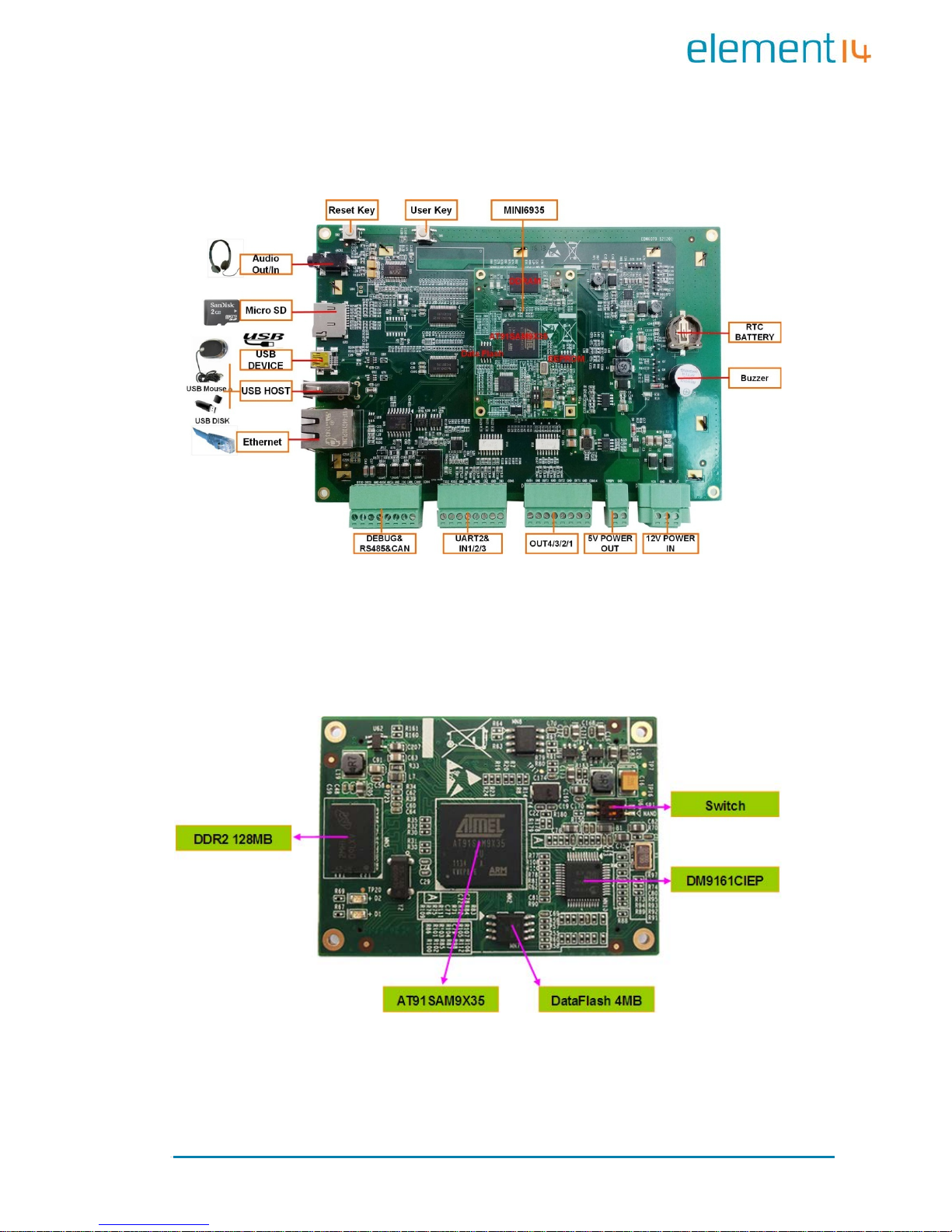
1.3 Expansion Board Interfaces
Figure 1: Base Board Interface with Mounted CPU Module
1.4 Core Board Interfaces
Figure 2: MINI6935 CPU Module (Front View )
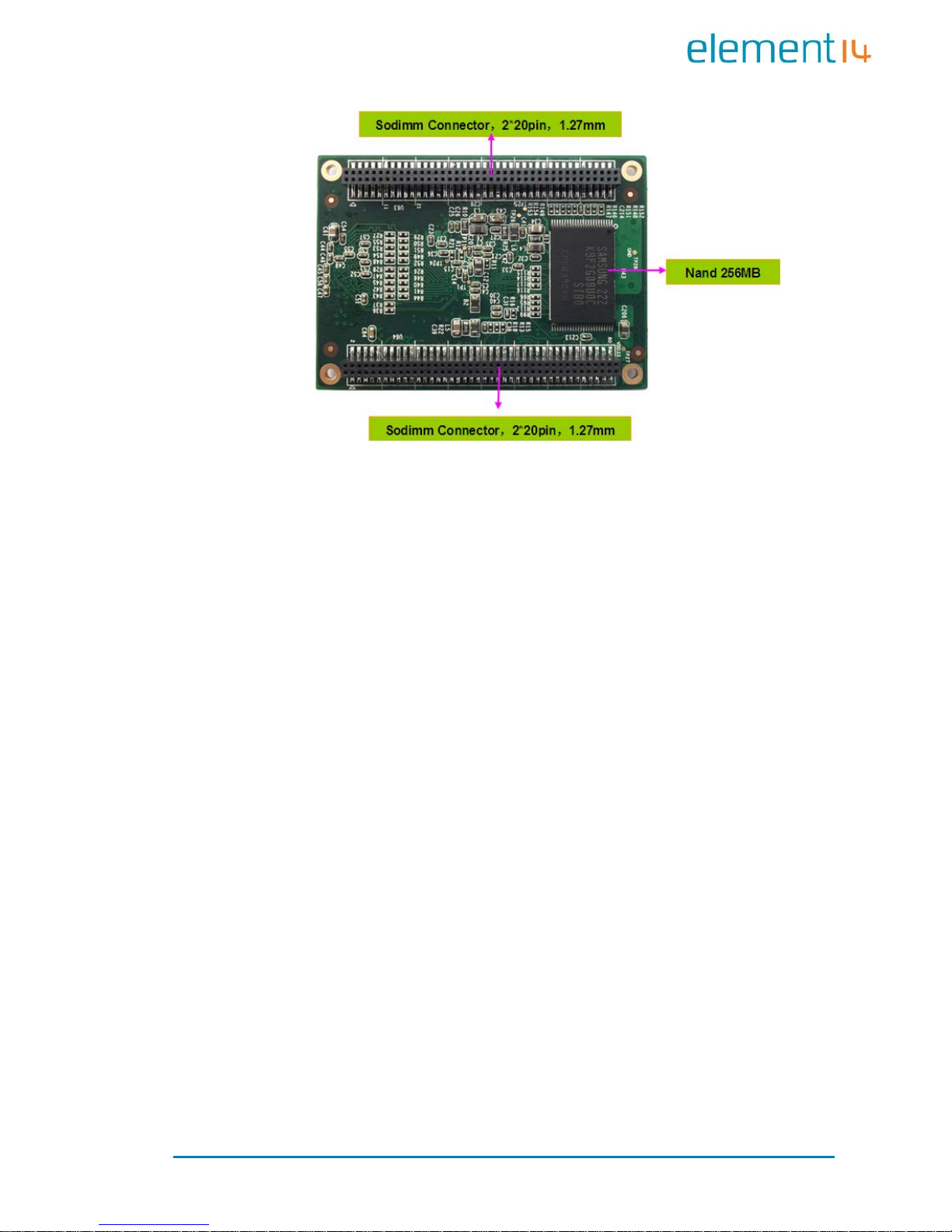
Page | 5
Figure 3: MINI6935 CPU Module (Rear View)
Page | 6
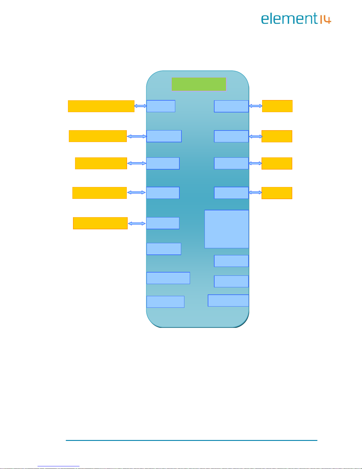
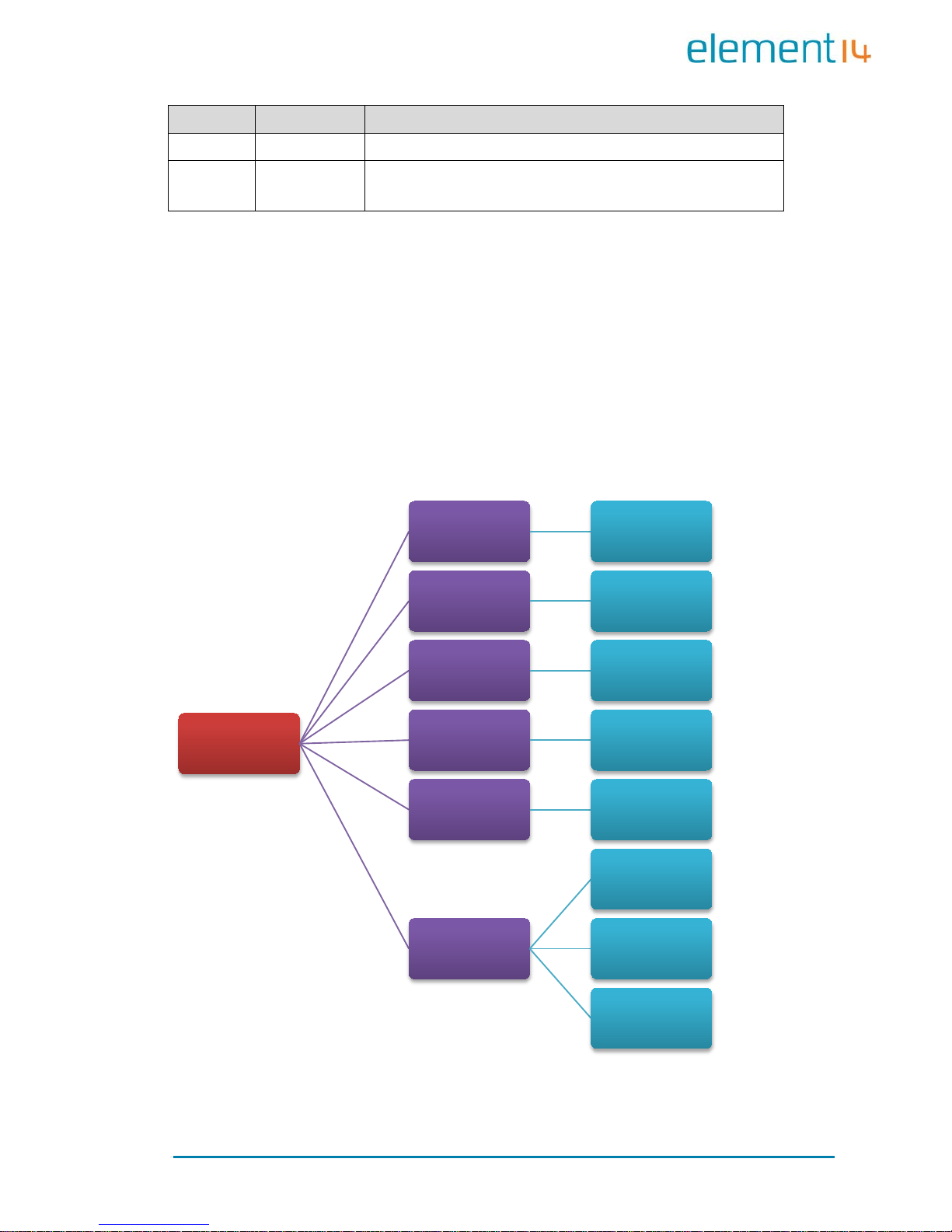
1.5 System Block Diagram
MAC
DM916
Data
AT25DF32 1 32MB
NAND
K9F2G08U0
TWI
AT24C04BN
AT91SAM9X35
RTC
Watchdog
Key
Reset
SD CARD
USB Device
USB Host
GPIO
ISO
LCD
800x480 RGB 7
Audio
RS232
Debug
Port
CAN 2.0
ISO
RS485
ISO
DDR2
MT47H64M16HR
Figure 4: Syst em Blo c k Diag ra m
Page | 7
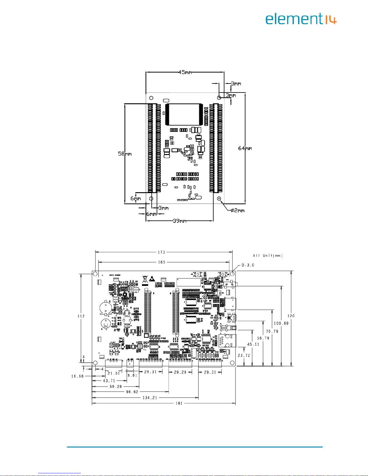
1.6 Physical Dimensions (mm)
Figure 5: Mini6935 Dimension s
Figure 6: Expansion Board Dimensions

Page | 8
Chapter 2: Hardware Features
2.1 Processor
Atmel AT91SAM9X35 ARM9 32-bit processor, 400MHz
16KB data cache, 16KB inst ruction cache, memory management
unit
64KB internal ROM and 32KB internal SRAM
2.2 On-Board Memory
128MB DDR2 SDRAM
256MB NAND Flash
4MB DataF lash
2.3 On-Board Interfaces
7” TFT LCD display, resolution of 800x480 with 24-bit colour depth
10/100Mbps Ethernet interface, using a DM9161CIEP chip,
extendable via expansion board
RS232 interface, 1 RS485 interface, 1 CAN interface
USB Host hi gh-speed interface
USB Device interface
Three GPIO Input interfaces
Four GPIO Output interfaces
Audio output interface, supportin g M P3 playback
Debugging Int erface, extendable via ex pansion board
TF card slot

Page | 9
2.4 Others
I/O interface LED indicator, 2 LED power indicators
Buzzer
I/O button
Reset button
RTC (no battery by default)
Watchdog
2.5 Operational Parameters
Operating Temperature: -10 °C ~ 70 °C
Operating Humidity: 0% ~ 90% (Non-condensing)
Power Supply: 12V@1.25A
Electrical Standards: CE, FCC and CCC
Product Dimensions: 181mm x 120mm
Page | 10
Chapter 3: Software Features
This chapter will briefly introduce the BSP package in the CD-ROM, example
applic ation s insta lled in the p rodu ct an d the AP I functions called by thes e
applications.
3.1 BSP Package
The CD-ROM provided with the EDM6070 co ntains a BSP (Board Support
package) which is used for building custom Linux systems. The table shown
below lists the contents of the BSP with corresponding descriptions.
Types Names Description
BIOS
Bootstrap Serial Flash
U-Boot
Serial Flash
Supports kernel and file system programming through
SAM-BA or USB fl ash drive (USB flash driv e is
recommended)
Device
Drivers
Serial Debugging and COM2 serial interface on CPU
RTC
Internal RTC of AT91SAM 9X35
Ethernet
10/100M Ethernet driver
Flash
NAND Flash and DataFlash driver
LCD
LCD driver, 800x480 resolution
Touch
Screen
Touchscreen controller on CPU
USB Host
USB Host driver
Watchdog
Built-in watchdog driver
SD Card
SD card driver
CAN Bu s
CAN bus
RS-485
RS-485 bus
LED Syste m sta tu s LED
BEEP
B
uzz er driver
Audio WM8731EDS audio output driver
Button Custom user button driver
GPIO GPIO driver, 3 input chan ne l s , 4 output channels
Kernel Linux-2.6.39 ROM/CRAM/EXT2/EXT3/FAT/NFS/JFFS2/YAFFS2/UBIFS
Page | 11
Types
Names
Description
file syst ems
Root File
System
UBIFS
Readable and writeable file system, supporting
compression storage
3.2 Example Applications
The Linux system installed in EDM6070 contains multiple example
applications under /home/app. Users can use those applications to
implement, test or demonstrate various product functionalities. The
following block diagram clearly shows the location of each example
application in the system.
Figure 7: Example App l ic ations (D irectory Str uc ture)
/home/app
COM UART Test
EVTEST
Event Devices
Test
GPIO GPIO Test
LED LED Test
BEEP Buzzer Test
CAN
CAN Test
CAN Receiver
Test
CAN Transmitter
Test
Page | 12
3.3 API Functions
Before you start to test the prod uct, it is necessary to learn about the API
functions used by the example applications. If you need to understand the
work ing princip le of an application in detail, read the source code stored
under “\02 Linux 2.6 Kit\01 Source Code\app\” in the CD-ROM
provided al ong wit h EDM6070.
The tables listed be low will sho w you the API functions called by some of
applications and the relevant information.
LED API Function
LED_API int led_ctrl (char *name, int onoff );
Source ledlib.h
Functionalities Turn on or off LEDs
Parameters
Name (LED’s name such asD6, D9 or D13)
onoff (0 for off, 1 for on)
Returned Values 0 for success, otherwise fail u r e
Examples led_ctrl ("D9", 1);
Buzzer API
Function
BEEP_API int beep_ctrl (char *name, int onoff);
Source beeplib.h
Functionalities Controls the buzzer to make sound or stop
Parameters
Name (buzzer name, normally there is only
one buzzer which is called “beep”)
onoff (0 for off, 1 for on)
Returned Values 0 for success, otherwise failure
Examples beep_ctrl ("beep", 1); beep_ctrl ("beep", 0);
Serial Interface
API Function
int OpenDev(char *Dev);
Source com_example.c
Functionalities Enable s erial d evices and acquire descriptors
Page | 13
Parameters
dev (character string of
serial devices, e.g.
“/dev/ttySAC0”)
Values more than 0 is a serial file descriptor,
less than 0 stands for failu r e
Returned Values com_example.c
void set _ s pe ed(int f d, in t s peed);
Source com_example.c
Functionalities Set the bitrate o f seri al interfaces
Parameters
fd (serial file descriptor)
speed (bitrate, e.g. 15200)
Returned Values None
int set_Parity(int fd ,int databits,int stop bit s,int parit y,i nt
flowctrl);
Source com_example.c
Functionalities
Set serial interface
data bits, stop bits, parity
check an d data flo w co nt rol
Parameters
fd (serial file descriptor)
databits (length o f data bit s)
stopbits (length of stop bits)
parity
(check type, N for no check, O for odd
check, E for even check)
flowctrl
(switch of hardware data follow
control, 1 for enable, 0 for disable)
Returned Values 0 for success, o t herwise failure
size_t read(int fd, const void *buf, size_t nbytes);
Source unistd.h
Functionalities
Called by system to acquire data received on
the serial interfaces
Parameters
fd (serial file descriptor)
buf (pointer t o t he rec eived data)
nbytes (data length about to be read, Byte)
Returned Values
Valu es less t han 0 stands for error, more than
0 stands for received data l ength (Byte)
size_t write(int fd, const void *buf, size_t nbytes);
Source unistd.h
Functionalities
Called by system to send data through the
serial interfaces
Parameters fd (serial file descriptor)
Page | 14
buf (pointer to the data about to be sent)
nbytes (length of data about to be sent, Byte)
Returned Values
Value of less than 0 stand s for an error, more
than 0 stands for a
data length being sent
(Byte)
int close(int fd);
Source unistd.h
Functionalities
Called by system to disable the serial
interfaces
Parameters fd (serial file descriptor)
Returned Values 0 for success, less than 0 stands fo r er ror
GPIO API Function
int open(const char *path, int oflags);
Source gpio_example.c
Functionalities Initialize the GPIO device no de
Parameters Path: /dev/gpio.0 oflags: O_RDWR
Returned Values 0 for success, o t herwise failure
int close(int fildes);
Source gpio_example.c
Functionalities Releas e GPIO
Parameters fildes: open returned file descriptor
Returned Values 0 for success, o t herwise failure
ioctl(fd, GPIO_GET_VALUE, pin);
Source gpio_example.c
Functionalities Read the logic level of the input pin
Parameters
Pin (GPIO pin name , such as GPIO_PB15)
fd (GPIO device descriptor)
Returned Values Return level value in digit 0 or 1
ioctl(fd, GPIO_S ET_ PI N, pin);
Source gpio_example.c
Functionalities
Allow the output pin provide a
high level
output
Parameters Pin (GPIO pin name, such as GPIO_PD18)
Returned Values None

Page | 15
ioctl(fd, GPIO_ CLR_ PIN , pin );
Source gpio_example.c
Functionalities
Allow the output pin to provide a
low level
output
Parameters
Pin (GPIO pin name , such as GPIO_PD18)
Returned Values None
Page | 16
Chapter 4: Demonstration and Test
Functions
This chap ter will introduce to the S mart Home Automation demo application
and how to use the example applications contained in the system to
implement functionality tests of the EDM6070, as we ll as a demonstr ation of
the LinuxQT graphics interface.
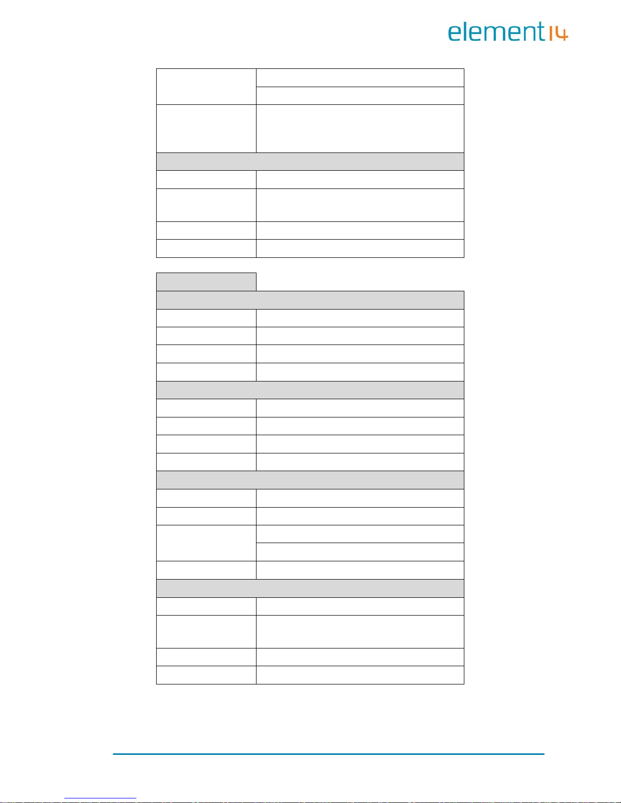
4.1 Smart Home Automation Demo
A Smart Home System demo application has been provided with the
EDM6070. This d emo applica tion enables EDM developers to qu ickly and
easily jumpstart their embedded Linux application development — without
first having to set up their development environment. Smart Home
automati on demo fe atures a Q T GUI appl ication with several custo m widgets,
including:
Climate Control
Light control
Thermostat control
Page | 17
Video player
4.1.1 Demo Features
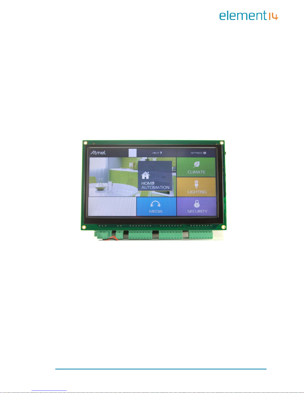
This demo showcases the control of various house functions including
heating, lighting, security and a media player. The major functions are
expounde d upon be lo w:
4.1.1.1 Climate Control
This ap plication allo ws the user to control the tem perature an d humidity
throughout the house on a room by room basis. There is also a display
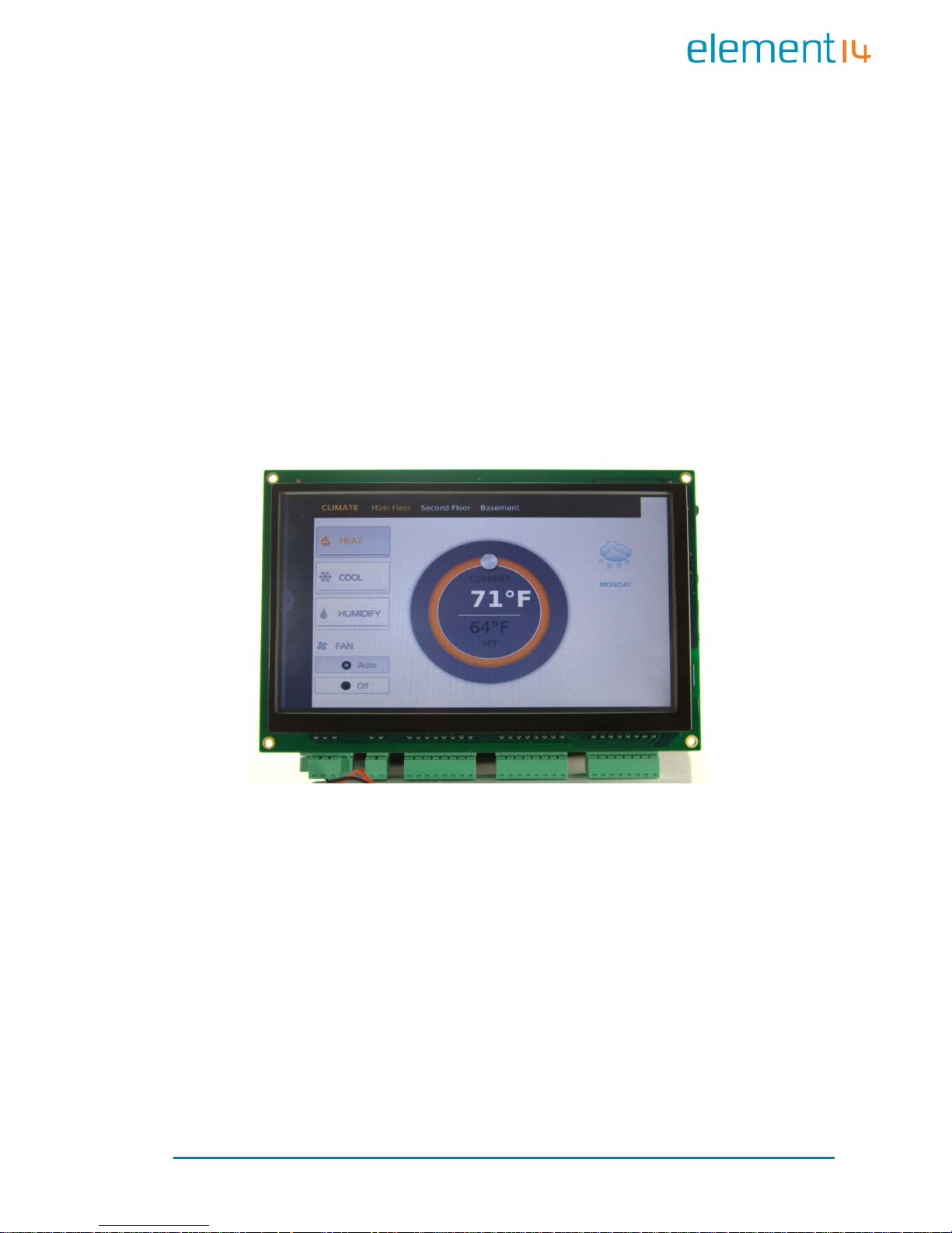
indicating the current weather which can be activated to display extra
information:
Page | 18
5 day forecast
Detailed current weather inf o rmation
Page | 19
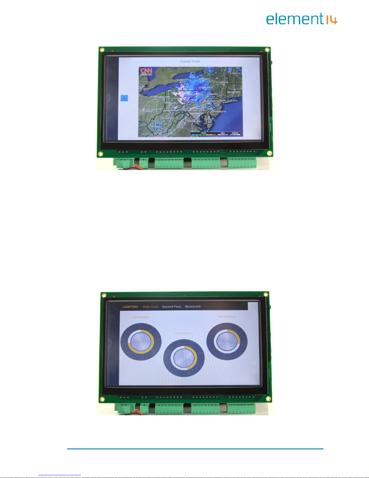
Pulse-doppler radar weather display
The weather information is updated via the internet and as such the
EDM6070 requires an internet connection in order to provide this
functionality
4.1.1.2 Lighting Control
Page | 20
The ligh tin g a p plicatio n a llo w s th e us er to set th e l ig h t levels in ea c h r o om
independently. The application emulates a standard dimmer switch making
the software both intuitive and user friendly
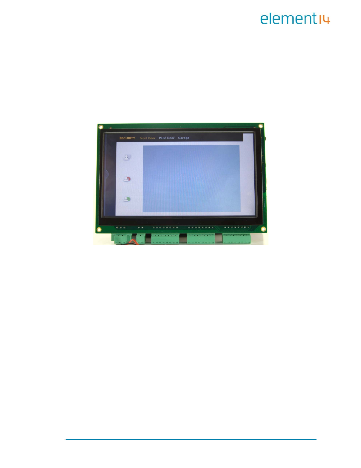
4.1.1.3 Security
The security applicati on allows the EDM6 070 to connect to cameras and door
locks at any user defined entrance. This allows the user to monitor the
entrance and either allow or deny access to the p ro perty
 Loading...