


CAMELIA 8M
8 MEGAPIXEL DIGITAL CAMERA
User guide
V 2.0 October 2001 Phone +33 (0) 1 49 75 96 00 - Fax +33 (0) 1 49 75 96 01 1/16
www.atmel-grenoble.com

CAMELIA 8M user guide
2/16
CAMELIA PACKAGE CONTENTS :
Depending on the selected configuration, a CAMELIA package may include :
CAMELIA camera
FGT frame grabber board
‘’Power supply’’ cable + ‘’RS232’’ cable
‘’Data & Sync’’ cable.
‘’COMMCAM’’ software.
FGT software.
documentation
SYSTEM REQUIREMENTS :
+24V(0.6A) power supply
Lens : NIKON or other Fmount lens
Lightning control (shutter/chopper or pulsed lightning).
GETTING STARTED :
connect the camera to one of the computer serial ports (COM1 or COM2) by using the
RS232 cable
power on the camera
install ‘’COMMCAM’’ software in your computer. (see "COMMCAM User Guide")
install FGT frame grabber board and FGT software in your computer. (see "FGT Frame
Grabber User Manual")
run the system

CAMELIA 8M user guide
3/16
1. IMAGING SYSTEM DESCRIPTION ...............................................................................................................4
2. CAMELIA 8M CAMERA...................................................................................................................................5
2.1 CCD.................................................................................................................................................................5
2.2 TIMING MODES.................................................................................................................................................5
2.3 LINE READOUT TIMING.....................................................................................................................................7
2.4 ANTI-BLOOMING BY CLOCKING........................................................................................................................7
2.5 COLOR OPERATION ...........................................................................................................................................8
2.6 ROIS................................................................................................................................................................8
2.7 ELECTRICAL INTERFACES .................................................................................................................................9
2.7.1 Power supply............................................................................................................................................ 9
2.7.2 Digital I/O................................................................................................................................................9
2.8 CAMERA CONFIGURATION VIA RS232 INTERFACE............................................................................................9
2.9 ELECTRO-OPTICAL PERFORMANCE.................................................................................................................10
2.10 GEOMETRICAL SPECIFICATIONS ..................................................................................................................12
2.11 ENVIRONMENTAL REQUIREMENTS..............................................................................................................13
2.12 IMAGE GRADE........................................................................................................................................13
2.12.1 TEST CONDITIONS...........................................................................................................................13
2.12.2 DEFINITIONS....................................................................................................................................13
3. CONNECTORS AND CABLES .......................................................................................................................14
3.1 ‘’DATA AND SYNC’’ CABLE............................................................................................................................14
3.2 ’POWER SUPPLY’’ CABLE ............................................................................................................................... 15
3.3 ‘’RS232’’ CABLE ...........................................................................................................................................15

CAMELIA 8M user guide
4/16
1. IMAGING SYSTEM DESCRIPTION
♦ CAMELIA camera is powered by a +24V power supply.
♦ CAMELIA camera is configured through the serial port of the computer.
♦ CAMELIA camera sends digital video to the FGT frame grabber.
♦ As CAMELIA 's CCD is a full frame sensor, you must use either pulsed lightning or a chopper/shutter in front of
the camera in order to have incident lightning on the CCD only during integration time. You must design an
electro-optical interface to drive camera, shutter/chopper or lightning by using the "SHUTTER" signal delivered
by the camera. If required, the system can send an external trigger or external ITC (integration time control
signal) to the camera.
POWER
RS232
DATA & SYNC
FRAME
GRABBER
COMPUTER
SERIAL
PORT
POWER SUPPLY
+24V
TRIG_ITC
ANALYZED OBJECT
SHUTTER / CHOPPER
ELECTRO-OPTICAL
INTERFACE
CAMELIA
LIGHTNING

CAMELIA 8M user guide
5/16
2. CAMELIA 8M CAMERA
2.1 CCD
♦ image format : 35.0mm(V) x 23.0mm(H)
♦ active pixels :
Mode (set via RS232) Image size (H x V)
No binning 2300 x 3500
2x2 pixel binning 1150 x 1750
4x4 pixel binning 574 x 875
♦ readout register along the small side of the image area. (vertical image)
♦ pixel geometry :
◊ 10µm(V) x 10µm(H).
◊ aperture ratio : 100%.
♦ anti-blooming by clocking.
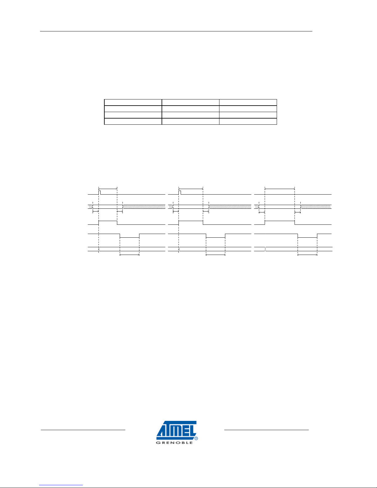
2.2 TIMING MODES
3 timing modes are available (set via RS232) :
♦ continuous : the camera delivers frames continuously :
◊ frame N+1 integration starts as soon as frame N readout is completed.
◊ integration time is set by RS232
♦ operation with external trigger : integration start is controlled by the user from the external signal TRIG :
◊ the rising edge of TRIG activates the start of the frame integration. This rising edge is synchronized by the
camera with a precision of 110µs
◊ integration time is set by RS232
◊ note : TRIG signal period must be greater than integration time plus frame readout time.
♦ operation with "integration time control" : integration is fully controlled by the user from the external signal ITC :
◊ the falling edge of ITC activates the start of the frame integration. This falling edge is synchronized by the
camera with a precision of 110µs
◊ the rising edge of ITC activates the stop of the frame integration. This rising edge is synchronized by the
camera with a precision of 110µs
◊ note : ITC signal period must be greater than integration time (defined by ITC low) plus frame readout
time.
2x2 and 4x4 pixel binning is possible to enable previewing modes.
Data rate is :
♦ pixel clock : 25 MHz
♦ frame readout time :
◊ normal mode : 370ms
◊ 2x2 pixel binning : 200ms.
◊ 4x4 pixel binning : 110ms.

CAMELIA 8M user guide
6/16
Timing diagram (for continuous operation) :
Timing diagram (for operation with "external trigger") :
Timing diagram (for operation with "integration time control") :
3
INT. TIME SET BY RS232
FRAME
INTEGRATION
shutter delay
video lines
2
1
FRAME
READOUT
2300 pixels
3500
3499
3498
5ms
SHUTTER
FEN
LEN
2
1
video lines
FRAME
INTEGRATION
INT. TIME SET BY RS232
TRIG
shutter delay
3
WAITINGFRAME
READOUT
2300 pixels
3500
3499
3498
SHUTTER
FEN
LEN
FRAME
READOUT
3
2300 pixels
FRAME
INTEGRATION
LEN
SHUTTER
FEN
ITC
2
1
video lines
shutter delay WAITING
3500
3499
3498

CAMELIA 8M user guide
7/16
2.3 LINE READOUT TIMING.
Duty cycle of the PCK is 50%.
Rising and falling edges : 1,5 nsec.
DATA(11..0)
LEN
PCK
first
pixel
last
pixel
2.4 ANTI-BLOOMING BY CLOCKING
Anti-blooming can be activated or inhibited (set via RS232) :
◊ anti-blooming OFF : this position is recommended if anti-blooming is not required for the application.
◊ anti-blooming ON : anti-blooming is activated.
CAMELIA 8M user guide
8/16
2.5 COLOR OPERATION
In ‘’3 shot color’’ mode, each image is made of 3 frames : red, green, blue :
◊ the camera must be operated either in ‘’external trigger’’ mode or in ‘’integration time control’’ mode.
◊ for each image, the user selects the color of the next frame by setting COLOUR_I1 and COLOUR_I2 input
signals. COLOUR_I1, _I2 must be valid in the time period between TRIG signal rising edge (or ITC signal
falling edge) and SHUTTER signal falling edge. (see timing there after)
◊ color definition is :
COLOUR_I2 COLOUR_I1 Frame Color
0 0 Red
0 1 Green
1 0 Blue
◊ integration time can be adjusted differently for each color (set via RS232). This allows to have a better
signal to noise ratio for the color with the lowest sensitivity (i.e. the blue)
◊ each frame requires a TRIG_ITC signal.
◊ CAMELIA 8M camera synchronizes COLOUR_I1, _I2 with the rest of the timing and sends COLOUR_O1,
_O2 to FGT frame grabber.
2.6 ROIS
Regions of interest.
CAMELIA 8M can operate in a “multi ROI” mode allowing masking of regions of the image and thus increasing frame
rate by a reduced readout time.
User defines up to 5 windows to be masked. In addition he specifies starting and ending addresses for each window.
Time reduction : about 92 µsec per masked line.
Two steps :
• Enter the number of regions masked by the CommCam command : F=X (X=0 to 5)
• Enter the list of starting and ending addresses by the CommCam command : Y=ssss/eeee/ssss/eeee/…/eeee/
For example : how to mask 2 regions of 500 lines each, one on the top of image, the second on the bottom, 1x1 pixel
binning :
CommCam commands : F=2 then Y=0/500/3000/3500/
In this example readout time will be reduced of 1000 lines equivalent to 92 msec.
FRAME "00"
(RED)
FRAME "01"
(GREEN)
FRAME "10"
(BLUE)
00 01
COLOUR_I
COLOUR_O
FEN
> 0 > 0
SHUTTER
00
> 0
RED
INTEGRATION
TIME
TRIG
GREEN
INTEGRATION
TIME
10
01
> 0 > 0
10
> 0
BLUE
INTEGRATION
TIME

CAMELIA 8M user guide
9/16
2.7 ELECTRICAL INTERFACES
2.7.1 POWER SUPPLY
Voltage Current
+24V
Min : +20V ; Max : +28V
0.6A
2.7.2 DIGITAL I/O
SYMBOL I/O DEFINITION LEVEL
TRIG_ITC I Timing control :
TRIG_ITC is either an external trigger or "integration time control"
depending on the timing mode configured via RS232.
operation with external trigger :
TRIG_ITC = TRIG
operation with "integration time control" :
TRIG_ITC = ITC
TRIG_ITC is synchronized by the camera line clock (jitter : 110 µs)
LVDS
COLOUR_I(1..0)
I Color selection of the next frame (in color mode) :
- "00" : red
- "01" : green
- "10" : blue
LVDS
S(11..0) O Digital video output : 12 bits LVDS
FEN Frame enable :
- FEN = 0 : frame data valid : active lines
- FEN = 1 : frame data not valid
LVDS
LEN O Line enable :
- LEN = 0 : line data valid : active pixels
- LEN = 1 : line data not valid
LVDS
PCK O Pixel clock LVDS
COLOUR_O(1..0) O Color identification of the current frame (in color mode) :
- "00" : red
- "01" : green
- "10" : blue.
LVDS
SHUTTER O shutter open/close :
- during integration : shutter = 1
- during readout : shutter = 0
delay between the falling edge of shutter and the start of readout :
- 4 positions : 1ms, 5ms, 10ms, 20ms. (set via RS232)
LVDS
Note : LVDS drivers / receivers :
♦ LVDS : Low Voltage differential Signal. (EIA 644 standard). All digital I/Os are differential : (signal+, signal-).
Specifications are given for signal+.
♦ manufacturer NS
♦ driver : DS90C031TM (SO16 package)
♦ receiver : DS90C032TM (SO16 package)
2.8 CAMERA CONFIGURATION VIA RS232 INTERFACE
Camera configuration is set by RS232 interface, using COMMCAM software (see "COMMCAM user guide").
Users who wishes to develop their own configuration software will read the "Camera RS232 interface user guide".
CAMELIA 8M user guide
10/16
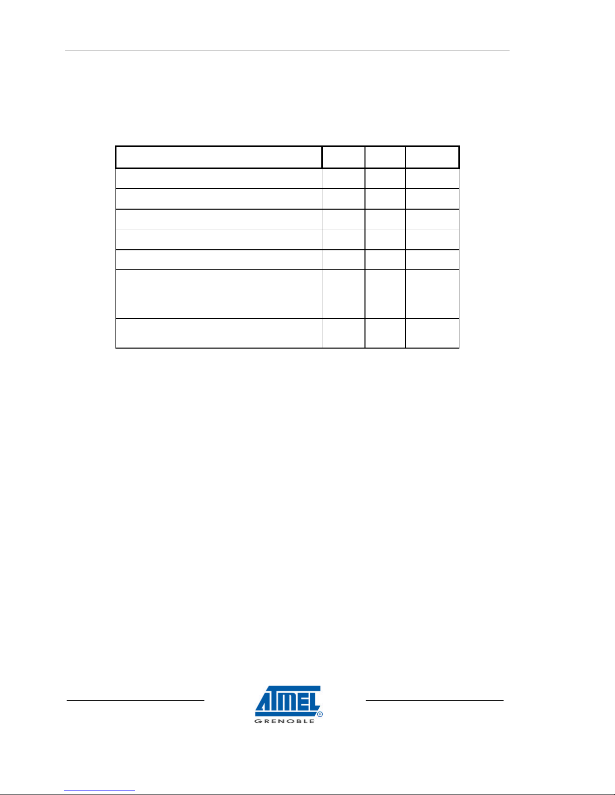
2.9 ELECTRO-OPTICAL PERFORMANCE
♦ Conditions :
◊ frame integration time : 40ms
◊ camera operating free air temperature : 25°C
♦ Performance :
Parameter Symbol Typical
Value
Unit
Full scale value
see note 2
VPE 4095 adu
Temporal noise
σ see note 3
VN 2.7 adu
Dark signal non uniformity
σ see note 4
DSNU 2 adu
Dynamic range
see note 5
DY 1500
Responsitivity
see note 6
R 50 adu/(lux.s)
Resolution
- horizontal contrast transfer function at Nyquist
- vertical contrast transfer function at Nyquist
see note 7
CTFh
CTFv
40%
40%
Anti-blooming
- over illumination capability
See note 8
8x
♦ note 1 : adu : arbitrary digital unit : 12 bit = 4095 adu or gray levels.
♦ note 2 : full scale value VPE : maximum digital video signal
♦ note 3 : temporal noise VN : r.m.s value in darkness. Measured by substracting 2 images pixel to pixel
♦ note 4 : dark signal non uniformity : r.m.s value. Excludes blemishes.
♦ note 5 : dynamic range DY :
◊ DY = VPE / VN
♦ note 6 : responsivity :
◊ conditions :
• CDS gain = 1x.
• Light source 3200K, BG38 2mm
• lens aperture : F/4.
• lux on the scene taking into account : scene reflectance 80%, lens transmission 80%
♦ note 7 : resolution :
◊ conditions :
• light source 3200K, BG38 2mm.
• VIDEO = 2000 adu, CDS gain = 1x.
♦ note 8 :
◊ anti-blooming ON
◊ integration time = 100ms.

CAMELIA 8M user guide
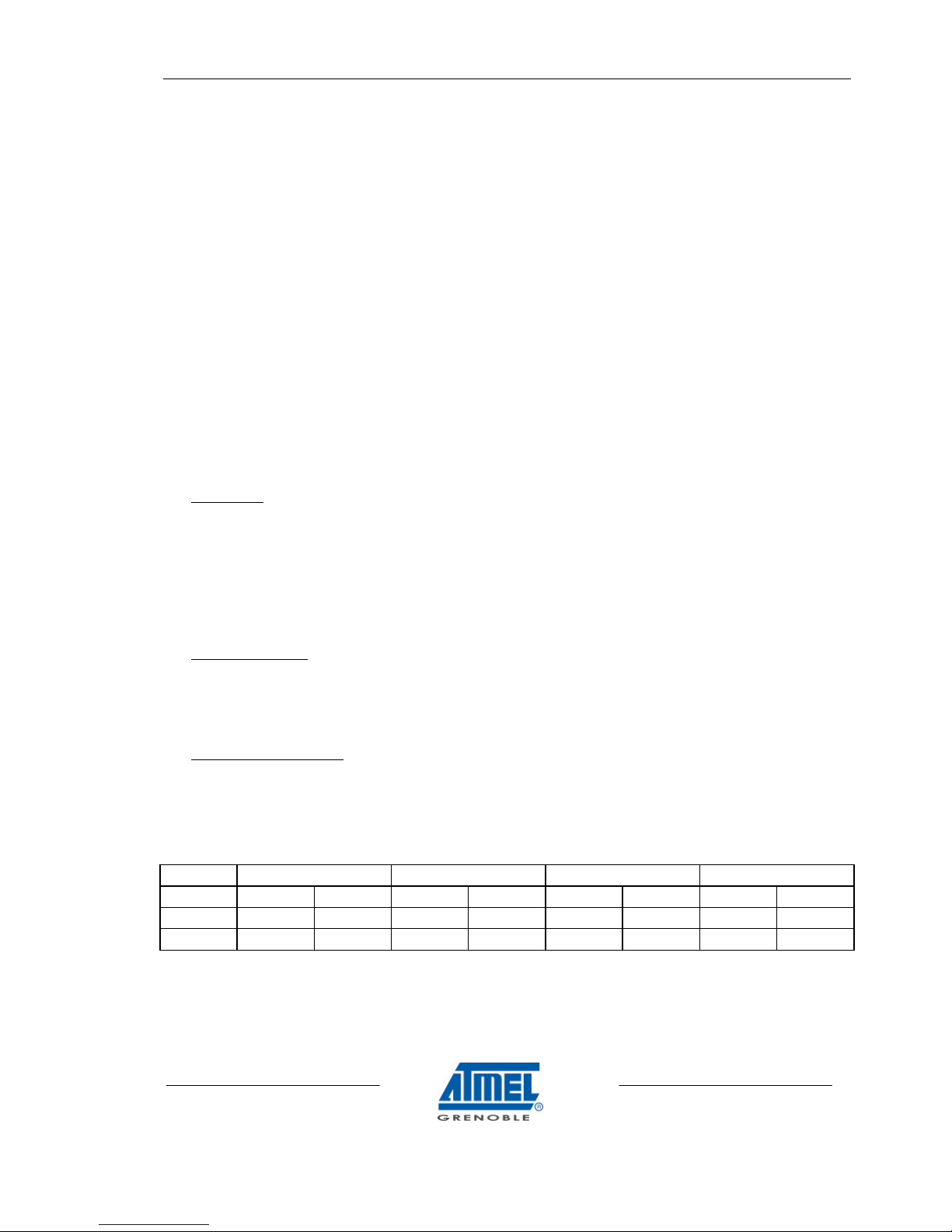
11/16
Note : µJ/cm2 measured on the CCD chip.
0
20000
40000
60000
Wavelength (nm)
Responsitivity (adu/uJ/cm2)
400 500 600 700 800 900 1000 1100
CAMELIA 8M
Spectrale response (adu/µJ/cm2)
CAMELIA 8M user guide
12/16
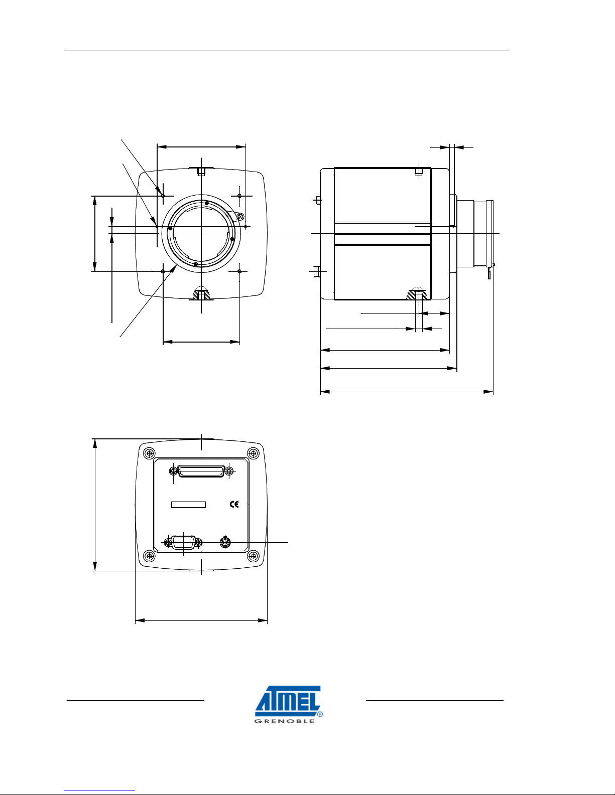
2.10 GEOMETRICAL SPECIFICATIONS
♦ Weight : 1400g.
REAR PANEL
112.0 mm
110.5 mm
DATA & SYNC
Made in France
RS 232
SN:
CAMELIA 8M
POWER
2 X ø 2.0 mm
4 X M3
(depth 6mm)
ø 66.0 mm
6.0 mm
64.0 mm
74.0 mm
64.0 mm
FRONT PANEL
4.0 mm
144.5 mm
2X 1/4_20 UNC 2B
114.0 mm
25.6 mm
108.0 mm
CAMELIA 8M user guide
13/16
2.11 ENVIRONMENTAL REQUIREMENTS
♦ operating temperature : 0°C / +50°C
♦ storage temperature : -20°C / 70°C
♦ operating humidity : < 80% at +35°C
♦ vibration : 2g sinusoidal, from 10Hz to 55Hz.
2.12 IMAGE GRADE
2.12.1 TEST CONDITIONS
• Room temperature
• Illumination conditions : 3200K Halogen lamp with BG38 Infrared filter and f/11 aperture
• Integration time = 100 ms
• Test under illumination at 50% of saturation level
2.12.2 DEFINITIONS
• Defect sizes
- Blemish : 1 x 1 defect.
- Cluster : blemish grouping of not more than a given number of adjacent defects :
1 x 1 < cluster 1 size ≤ 2 x 2
2 x 2 < cluster 2 size ≤ 5 x 5
- Column : one-pixel-wide column with more than 7 contiguous defective pixels.
- Defect separation : Defects are separated by no less than "D min" pixels in any direction.
- Note : all defects are non contiguous.
• Defects in darkness
- blemish or cluster : pixel(s) whose signal deviate(s) more than 160 adus from the
average output signal
- Column : column whose signal deviates more than 16 adus from the
average output signal
• Defects under illumination
- blemish or cluster : pixel(s) which deviate(s) by more than ±20% from the average output
signal
- column : column which deviates by more than 10 % from the average output signal
Blemishes Cluster 1 Cluster 2 Column
Grade Total D min Total D min Total D min Total D min
E
≤ 500
3
≤ 30
50
≤ 6
100
≤ 5
150
H
≤ 300
3
≤ 10
50 0 - 0 -
Without any specification, E grade will be used on Camelia cameras.

CAMELIA 8M user guide
14/16
3. CONNECTORS AND CABLES
3.1 ‘’DATA AND SYNC’’ CABLE
♦ On camera side :
◊ 50 points HIROSE connector : HIROSE DX10A-50S.
◊ mating connector on cable side : HIROSE DX40-50P ; shell : HIROSE DX50-CV1.
◊ Pin-out :
Pin n° Signal Pin n° Signal
1 PCK+ 26 LEN+
2 PCK- 27 LEN3 FEN+ 28
COLOUR_O1+ (1)
4 FEN- 29
COLOUR_O1-(1)
5
COLOUR_O2+ (1)
30 GROUND
6
COLOUR_O2-(1)
31 GROUND
7 PDATA0+ 32 PDATA1+
8 PDATA0- 33 PDATA19 PDATA2+ 34 PDATA3+
10 PDATA2- 35 PDATA311 PDATA4+ 36 PDATA5+
12 PDATA4- 37 PDATA513 PDATA6+ 38 PDATA7+
14 PDATA6- 39 PDATA715 PDATA8+ 40 PDATA9+
16 PDATA8- 41 PDATA917 PDATA10+ 42 PDATA11+
18 PDATA10- 43 PDATA1119 GROUND 44 NC
20 GROUND 45 NC
21 SHUTTER+ 46 TRIG_ITC+
22 SHUTTER- 47 TRIG_ITC23
COLOUR_I1+(1)
48
COLOUR_I2+(1)
24
COLOUR_I1-(1)
49
COLOUR_I2-(1)
25 NC 50 NC
Notes :
◊ NC : not connected.
◊ (1) : grey cells : not used for CAMELIA COLOR : must be left unconnected
◊ a "Data + Sync" cable is provided with FGT Frame grabber, including a part to be connected to the
electro-optical interface, and the second one to the "FGT" frame grabber : see "FGT Frame Grabber User
Manual".
♦ On frame grabber side :
◊ 50 points MDR 3M connector : 10150-6000EL.
◊ Pin-out compatible to frame grabber FGT.

CAMELIA 8M user guide
15/16
3.2 ’POWER SUPPLY’’ CABLE
Pin Number
At camera output
Signal Pin Number
At end of power
supply cable
5 +24V 1
6 +24V 2
NC 3
NC 4
NC 5
1 GROUND 6
2 GROUND 7
NC 8
NC 9
Hirose 6 pins male
HR10A-7R-6P
SUBD9 male
♦ notes :
◊ NC : not connected.
◊ A "power supply " cable is provided with FGT Frame grabber.
3.3 ‘’RS232’’ CABLE
♦ On camera Dsub 9pins.
♦ On computer side Dsub9 female, pin out compatible with computer serial port
♦ note : pin out is the same on camera side and on computer side.
Pin Number
At camera output
Signal
1 NC
2 RX
3 TX
4 NC
5 GROUND
6 NC
7 TRS
8 CTS
9 NC
♦ notes :
◊ NC : not connected.
◊ A "RS232 " cable is provided with FGT Frame grabber.

CAMELIA 8M user guide
16/16
Information furnished is believed to be accurate and reliable. However Atmel-Grenoble assumes no responsibility for the
consequences of use of such information nor for any infringement of patents or other rights of third parties which may result from its
use. No license is granted by implication or otherwise under any patent rights of Atmel-Grenoble. Specifications mentioned in this
publication are subject to change without notice. This publication supersedes and replaces all information previously supplied.
Atmel-Grenoble products are not authorised for use as critical components in life support devices or systems without express
written approval from Atmel-Grenoble.
© 2001 Atmel-Grenoble- Printed in France - All rights reserved.
This product is manufactured by Atmel-Grenoble- 38521 SAINT-EGREVE - FRANCE.
For further information please contact :
Atmel-Grenoble – 2, Allée Maryse Bastié – Z.I. d’Orlytech - 91781 WISSOUS Cedex - FRANCE Phone +33 (0)1 49 75 96 00 - Fax +33 (0) 1 49 75 96 01.
Internet : http://www.atmel-grenoble.com
 Loading...