

Page 1
Operation manual for BLHeli Atmel Rev11.x
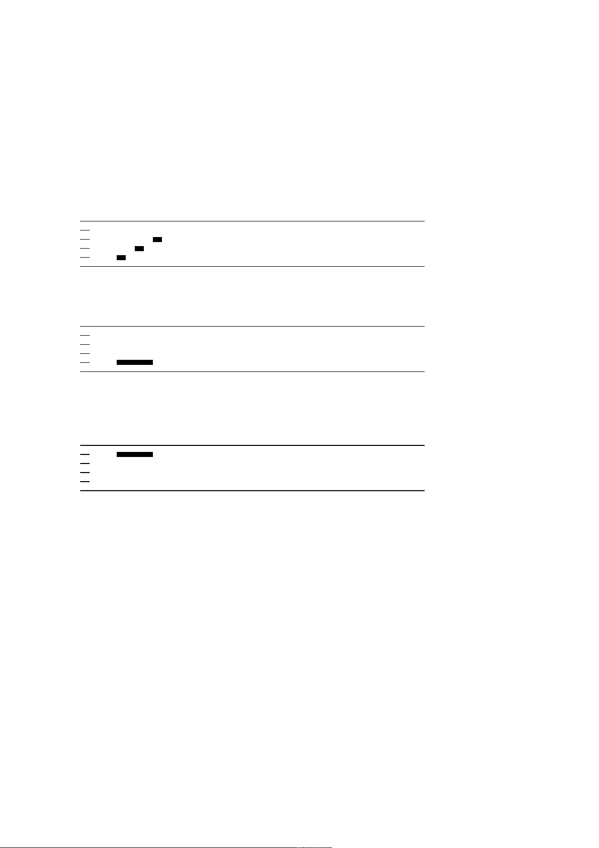
Normal operation:
This procedure is used for PWM input signal.
Power up:
Once
Throttle up detected (arming sequence start):
Once
The maximum throttle in this interval sets the ”arm” target for the governor.
Zero throttle detected (arming sequence end):
After this, the motor will run.
Once
Document rev 11.x
Page 2
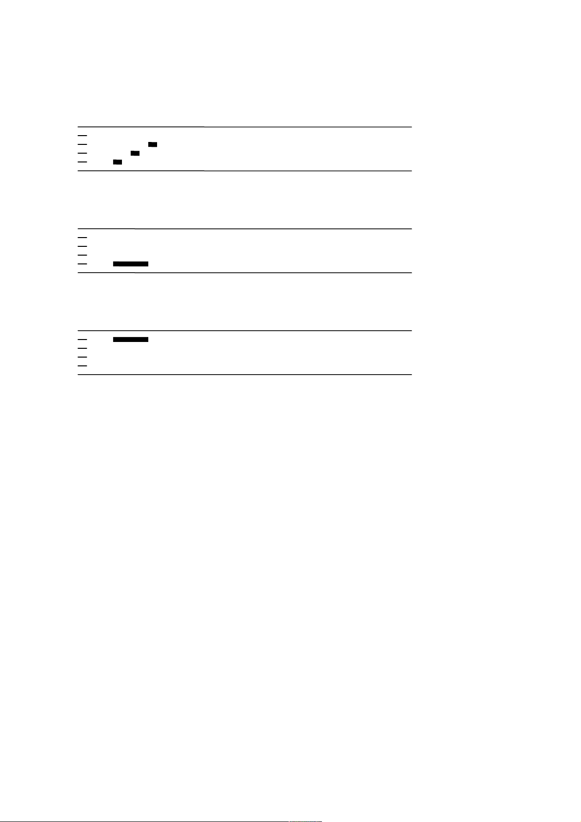
Normal operation:
This procedure is used for PPM input signal.
Power up:
Throttle signal detected (arming sequence start):
Zero throttle detected (arming sequence end):
Once
Once
After this, the motor will run.
Once
Document rev 11.x
Page 3
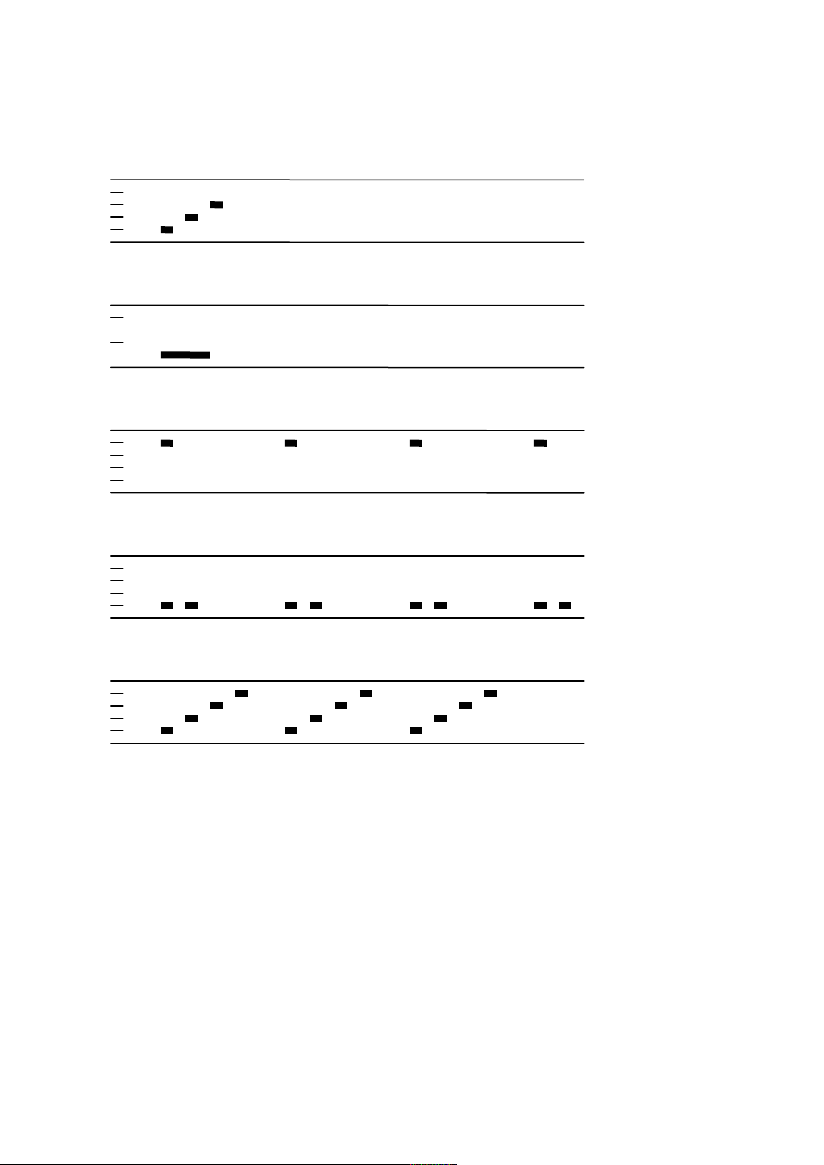
Entering programming mode:
This procedure is used for PWM input signal.
Power up:
Throttle up detected (arming sequence start):
Full throttle detected (start of entering programming mode):
Once
Once
Infinite
Zero throttle detected (continue entering programming mode):
Infinite
Full throttle detected (programming mode entered):
Once
The above description is for main or multi.
For the tail, follow the same sequence, but use right rudder as full throttle and left rudder as
zero throttle.
Document rev 11.x
Page 4
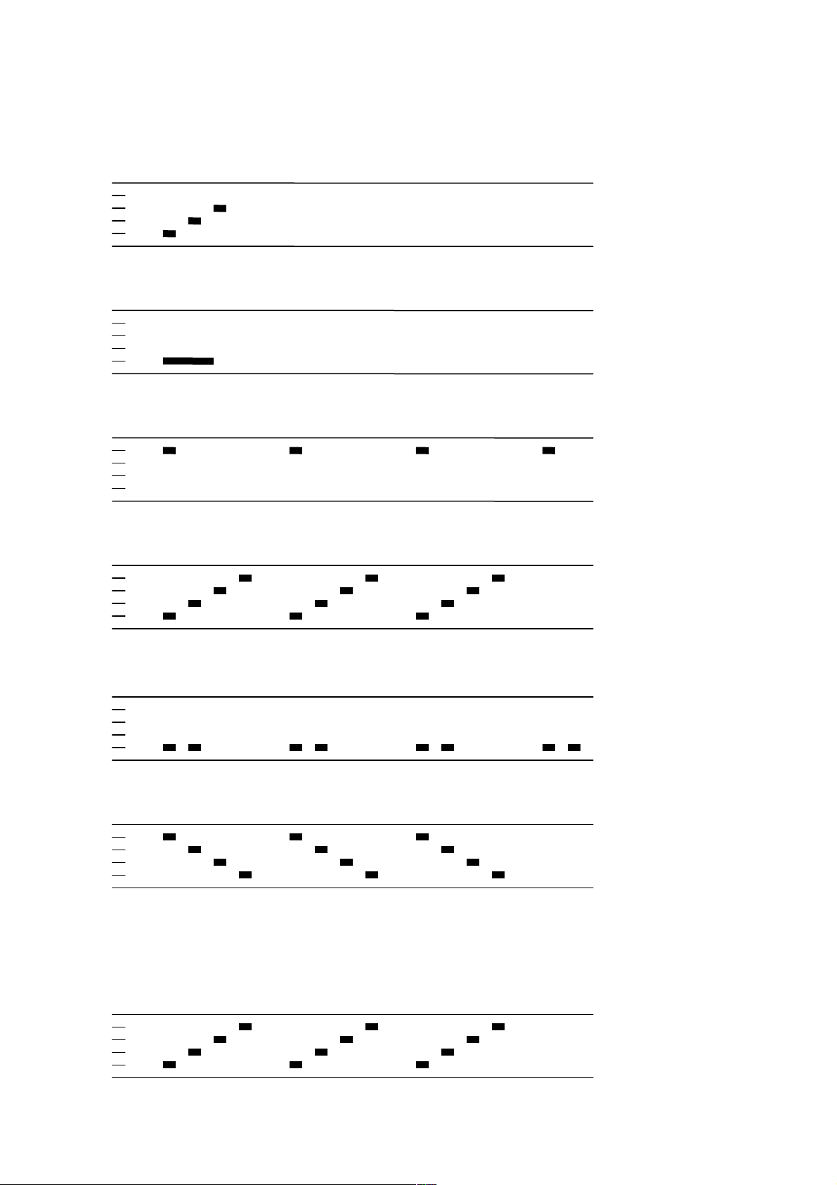
Throttle range calibration and entering programming mode:
This procedure is used for PPM input signal.
Power up:
Once
Throttle signal detected (arming sequence start):
Once
When throttle is above midstick (measuring max throttle):
While measuring
If throttle is above midstick for 3 seconds:
Once
This beep sequence indicates that max throttle has been stored
When throttle is below midstick (measuring min throttle):
While measuring
If throttle is below midstick for 3 seconds:
Once
This beep sequence indicates that min throttle has been stored
At this point throttle calibration values are stored. You may remove power from the ESC, if
you just wanted to do a throttle calibration and not enter programming mode.
Full throttle detected:
This beep sequence indicates that programming mode is entered
Document rev 11.x
Once
Page 5

Programming mode:
Function 1, parameter value 1
Function 1, parameter value 2
…etc…
Function 2, parameter value 1
Once
Once
Once
…etc…
If the throttle stick is moved to zero during one of the above sequences, the parameter value
of that function is selected and stored. And you will hear this sound:
Parameter value stored
Once
The ESC then resets itself.
If the throttle stick is moved below max (but not to zero), the current parameter will be
skipped, and programming will proceed to the next parameter. This way it is possible to
access the later parameters without going through all the beeps.
It is generally a good idea to go to full throttle again before selecting a parameter, to make
sure you have selected the right parameter.
Throttle is read in the 1 second pause between the function/parameter beeps.
If the throttle stick is never moved to zero, the ESC will load the defaults and then reset itself
after the last parameter value of the last function. This is a convenient way of setting all
parameters to defaults.
If power is disconnected during the programming sequence, then no changes are done to the
programmed values.
Document rev 11.x
Page 6

Programming functions and parameter values:
Programming parameter value table main:
Function 1 2 3 4 5 6 7 8 9 10 11 12 13
1 - Governor P gain 0.13 0.17 0.25 0.38 0.50 0.75
2 - Governor I gain 0.13 0.17 0.25 0.38 0.50 0.75
3 - Governor mode
4 - Governor range
5 - Low voltage limit (/cell) Off 3.0V 3.1V
6 - Startup power** 0.031 0.047 0.063 0.094 0.125 0.188 0.25 0.38 0.50 0.75 1.00 1.25 1.50
7 - Commutation timing Low MediumLow
8 - Throttle change rate 2 3 4 6 8 12 16 24 32 48 64 128
9 - Damping force
10 - Pwm frequency High
11 - Demag compensation
12 - Rotation direction
13 - Input pwm polarity
*: Governor arm mode is only supported with PWM input signal
**: Default startup power varies by ESC. Generally the default power is lower for larger ESCs.
Tx
High
VeryLow
Off
Normal
Positive
Arm* Setup Off - - - - - - - - -
Middle Low - - - - - - - - - -
3.2V
Medium
Low MediumLow MediumHigh
Low
Low High - - - - - - - - - Reversed - - - - - - - - - - Negative - - - - - - - - - - -
DampedLight
MediumHigh
- - - - - - - - - -
3.3V 3.4V - - - - - - -
High - - - - - - - -
High Highest - - - - - - -
1.00
1.00
Default values are marked in bold green.
If for some reason there is an error in the eeprom/flash write operation (e.g. due to loss of power or low voltage), defaults will be loaded.
1.5 2.0 3.0 4.0 6.0 8.0
1.5 2.0 3.0 4.0 6.0 8.0
255
Document rev 11.x
Page 7

Programming parameter value table tail:
Function 1 2 3 4 5 6 7 8 9 10 11 12 13
1 - Tail gain 0.75 0.88
2 - Tail idle speed Low MediumLow Medium
3 - Startup power** 0.031 0.047 0.063 0.094 0.125 0.188 0.25 0.38 0.50 0.75 1.00 1.25 1.50
4 - Commutation timing Low MediumLow
5 - Throttle change rate 2 3 4 6 8 12 16 24 32 48 64 128
6 - Damping force VeryLow Low MediumLow MediumHigh
7 - Pwm frequency High Low
8 - Demag compensation
9 - Rotation direction
10 - Input pwm polarity
*: Only enabled for some ESCs.
**: Default startup power varies by ESC. Generally the default power is lower for larger ESCs.
Off
Normal
Positive
Low High - - - - - - - - - Reversed Bidirectional - - - - - - - - - Negative - - - - - - - - - - -
1.00
Medium
DampedLight Damped*
1.12 1.25 - - - - - - - -
MediumHigh
MediumHigh
High - - - - - - - -
High - - - - - - - -
High
- - - - - - - - -
Highest - - - - - - -
255
Default values are marked in bold green.
If for some reason there is an error in the eeprom/flash write operation (e.g. due to loss of power or low voltage), defaults will be loaded.
Document rev 11.x
Page 8

Programming parameter value table multi:
Function 1 2 3 4 5 6 7 8 9 10 11 12 13
1 - Closed loop P gain 0.13 0.17 0.25 0.38 0.50 0.75 1.00 1.5
2 - Closed loop I gain 0.13 0.17 0.25 0.38 0.50 0.75 1.00 1.5
3 - Closed loop mode HiRange MidRange LoRange
4 - Multi gain 0.75 0.88
5 - Low voltage limit (/cell)
6 - Startup power** 0.031 0.047 0.063 0.094 0.125 0.188 0.25 0.38 0.50 0.75 1.00 1.25 1.50
7 - Commutation timing Low MediumLow
8 - Throttle change rate 2 3 4 6 8 12 16 24 32 48 64 128
9 - Damping force VeryLow Low MediumLow MediumHigh
10 - Pwm frequency
11 - Demag compensation Off
12 - Rotation direction
13 - Input pwm polarity
*: Only enabled for some ESCs.
**: Default startup power varies by ESC. Generally the default power is lower for larger ESCs.
Off
High
Normal
Positive
3.0V 3.1V 3.2V 3.3V 3.4V - - - - - - -
Low DampedLight Damped* - - - - - - - - -
Low
Reversed Bidirectional - - - - - - - - - Negative - - - - - - - - - - -
1.00
Medium
High - - - - - - - - - -
Off
1.12 1.25 - - - - - - - -
MediumHigh
- - - - - - - - -
High - - - - - - - -
High
Highest
- - - - - - -
2.0
2.0
3.0 4.0 6.0 8.0
3.0 4.0 6.0 8.0
255
Default values are marked in bold green.
If for some reason there is an error in the eeprom/flash write operation (e.g. due to loss of power or low voltage), defaults will be loaded.
Document rev 11.x
Page 9

Programming parameters for main:
In the governor “tx” mode, the throttle value while running sets the speed target for the governor.
In this mode, the throttle curve when flying should be flat.
In the governor “arm” mode the maximum throttle seen during the arming sequence will set the speed target for the governor.
Note that governor “arm” mode is not supported for PPM input signal.
In the governor “setup” mode the governor target is stored in the ESC. It’s default value is 70% (about 4800rpm on mCPX with a 6pole motor
and an 8T pinion). The value can be changed with configuration software.
In governor “arm” and “setup” modes, the throttle curve when flying does not influence headspeed.
Throttle curve can be set to a V-curve for the desired main to tail mix (this mix is in the mCPX 3in1).
Throttle must be above 20% in these modes. Values below 20% will cause spooldown.
Governor P gain sets the proportional gain for the governor.
This setting controls the gain from speed error to motor power.
Governor I gain sets the integral gain for the governor.
This setting controls the gain from integrated speed error (summed over time) to motor power.
Governor range sets the available range of speeds that the governor can operate on.
- For the high range, throttle values from 25% to 100% will lead to governor targets from 70000 to 208000 electrical rpm
- For the middle range, throttle values from 25% to 100% will lead to governor targets from 39000 to 156000 electrical rpm
- For the low range, throttle values from 25% to 100% will lead to governor targets from 20000 to 89000 electrical rpm
The low range is primarily intended for low pole count motors (e.g. 2-pole inrunners).
The low voltage limit sets the voltage at which motor power is reduced.
Motor power is reduced while at this voltage, but only temporarily, and full power is resumed if the voltage rises again.
Low voltage limiting can also be disabled.
Document rev 11.x
Page 10

Programming parameters for multi:
In the closed loop mode, the throttle value while running sets the rpm target of the motor.
Closed loop P gain sets the proportional gain for the rpm control loop.
This setting controls the gain from speed error to motor power.
Closed loop I gain sets the integral gain for the rpm control loop.
This setting controls the gain from integrated speed error (summed over time) to motor power.
Closed loop mode sets the range of speeds that the control loop can operate on.
- For the high range, throttle values from 0% to 100% linearly correspond to rpm targets from 0 to 200000 electrical rpm
- For the middle range, throttle values from 0% to 100% linearly correspond to rpm targets from 0 to 100000 electrical rpm
- For the low range, throttle values from 0% to 100% linearly correspond to rpm targets from 0 to 50000 electrical rpm
When closed loop mode is set to off, the control loop is disabled.
Programming parameters for tail/multi:
Tail/multi gain scales the power applied to the motor for a given input.
Beware that a low tail/multi gain will also limit the maximum power to the motor.
Tail idle speed is the speed of the motor during the delayed stop.
Rotation direction can be set to "bidirectional" for tail and multi codes.
In this mode, center throttle is zero and above is fwd rotation and below is reverse rotation.
Bidirectional operation is only supported for PPM input signal.
When bidirectional operation is selected, programming by TX is disabled.
Document rev 11.x
Page 11

Programming parameters for main/tail/multi:
Startup is always done with the direct startup method, which runs the motor using back emf detection from the very start. In this mode power is
given by the throttle used, but limited to a maximum level. This maximum level can be controlled with the startup power parameter. Beware that
setting startup power too high can cause excessive loading on ESC or motor!
Commutation timing can be adjusted in three steps. Low is about 00, mediumlow 80, medium 150, mediumhigh 230 and high 300.
Typically a medium setting will work fine, but if the motor stutters it can be beneficial to change timing.
Some motors with high inductance can have a very long commutation demagnetization time. This results in motor stop or stutter upon quick
throttle increase, particularly when running at a low rpm. Setting timing to high will allow more time for demagnetization, and often helps.
The throttle change rate parameter is an additional mechanism to avoid demagnetization problems. Setting this parameter to a low value will
result in slow changes in motor power. Which of course is not desirable in order to have a responsive motor, but in some cases it can be required.
This parameter determines how many steps motor power is allowed to increase for each new received input pulse. Full motor power is 255 steps.
So, e.g. for a 400Hz input rate and a throttle change rate setting of 2, motor power can change 2 steps every 2.5ms. Which means that zero to full
power will take (255/2)*2.5ms=319ms, which is really slow. On the other hand, the default setting of 255 means that motor power can change
from zero to full power instantly.
Please note that the throttle change rate parameter does not have any effect when running main governor or multi close loop.
High pwm frequency is around 16kHz, and low pwm frequency is around 8kHz.
One benefit of using a low pwm frequency is that the step from almost full power to full power becomes smaller. On the other hand, 8kHz is in
the audible frequency range, and also there is a step in power when the motor rotation frequency is equal to the pwm frequency.
Pwm damped mode adds loss to the motor for faster retardation. Damped mode always uses high pwm frequency.
In full damped mode, all three motor terminals are shorted when pwm is off, while in damped light mode, two motor terminals are shorted.
The full damped mode is only supported on some ESCs (where fet switching is sufficiently fast).
If one of the damped modes is selected, then the damping strength can be varied.
If damping is highest, loss is added in all pwm cycles.
If damping is high, loss is added in 7 out of 9 pwm cycles.
If damping is medium high, loss is added in 3 out of 5 pwm cycles.
If damping is medium low, loss is added in 2 out of 5 pwm cycles.
Document rev 11.x
Page 12

If damping is low, loss is added in 1 out of 5 pwm cycles.
If damping is very low , loss is added in 1 out of 9 pwm cycles.
Damped mode may result in uneven running at low speeds on some motor/ESC/voltage combinations.
This can be seen on high electrical rpm systems, with high damping force and an ESC with slow switching fets.
If this is a problem, reduce the damping force or use an ESC with faster switching fets.
The rotation direction setting can be used to reverse motor rotation.
The input pwm polarity setting can be used to inverse the throttle behaviour. This is intended to be used with receivers that provide negative
pwm (at least some Walkeras do). When using PPM input it must be set to positive.
Document rev 11.x
Page 13

Demag compensation is a feature to protect from motor stalls caused by long winding demagnetization time after commutation. The typical
symptom is motor stop or stutter upon quick throttle increase, particularly when running at a low rpm. As described earlier, setting high
commutation timing normally helps, but at the cost of efficiency. Throttle change rate can also be reduced, but at the cost of slower throttle
response.
The demag compensation is an alternative way of combating the issue. First of all, it detects when a demag situation occurs.
- In this situation, there is no info on motor timing, and commutation proceeds blindly with a predicted timing.
- In addition to this, motor power is cut off some time before the next commutation.
- As a third countermeasure, power is cut continuously when consecutive commutations give demag trigs.
These three mechanisms are used to a varying degree as shown below, selected by the demag compensation parameter
Demag compensation Off Low High
Blind commutation advance 22.5 7.5 7.5
Power off time 0 15 22.5
Power off upon consecutive trigs No Yes Yes
The values are in degrees. A motor electrical revolution is 360 degrees, and a commutation cycle is 60 degrees.
As shown in the above table, power off time will depend upon the selected commutation timing.
Generally, a higher value of the demag compensation parameter gives better protection.
If demag compensation is set too high, maximum power can be somewhat reduced.
Programming parameters that can only be accessed from configuration software (BLHeliSetup, BLHeliTool):
- Throttle minimum and maximum values for PPM input (will also be changed by doing a throttle calibration).
- Throttle center value for bidirectional operation with PPM.
- Governor setup mode rpm target.
- Beep strength, beacon strength and beacon delay.
- Programming by TX. If disabled, the TX can not be used to change parameter values (default is enabled).
- Re-arming every start. If enabled, a new arming sequence will be required for every startup, not just the first after poweron (default is disabled).
- High/low BEC voltage for ESCs that support it.
Document rev 11.x
Page 14

Arming sequence:
Power on
Arm start
Max throttle
Arm end
Run
100%
0% Time
The figure below shows an example of throttle value versus time.
during arm
3 beeps
1 low beep
1 high beep
At power on, the ESC beeps 3 beeps.
For PWM input, the following applies:
When throttle is raised above zero, it beeps one low tone beep. This signals the start of the arming sequence.
When throttle is reduced to zero again, it beeps one high tone beep. This signals the end of the arming sequence.
For PPM input, the following applies:
When throttle signal is detected, it beeps one low tone beep. This signals the start of the arming sequence.
Then, when or if throttle is zero, it beeps one high tone beep. This signals the end of the arming sequence.
For a main motor esc running with PWM input, throttle is monitored during the arming sequence. The maximum value of throttle is recorded.
If governor arm mode is selected, this value will be used as the governor speed target when the motor starts running.
When running, the throttle input has no effect, as long as it is not below 20%.
Also, if 100% throttle is detected during the arming sequence, the ESC starts entering programming mode.
Document rev 11.x
Page 15

The main motor has a soft spoolup of about 7 seconds for full power. The spoolup is done in three phases, in order to be soft enough for the heli not
to move, particularly before tail rpm is high enough to give some tail authority. In the first phase power is limited to the startup power for about one
second. Then the power limit is slowly increased over the next three seconds. And in the final phase the power limit is increased more rapidly, until
full power is available.
If the esc is armed and sees zero throttle for a given time, it beeps beacon beeps, which are about 1 beep per second
Auto bailout (for main):
The auto bailout function works as described below.
The first start after powerup will always have a soft spoolup.
When the motor is fully spooled up, auto bailout is armed.
When auto bailout is armed, spoolup will be faster, with about 2 seconds for full power.
If then throttle is at a low non-zero value bailout remains armed. Even if the motor stops at times.
If a zero throttle value is seen, auto bailout is disarmed immediately, and the next spoolup will be soft.
Auto bailout only works for governed main motor operation.
For non-governed main motor operation, throttle response is always fast after spoolup is done.
Document rev 11.x
Page 16

Input signal:
The ESC accepts both positive and negative PWM, as well as PPM as input signal.
The type of input signal is auto detected during the arming sequence.
The only input signal that requires changing the default parameters, is negative PWM.
PWM is accepted as 12kHz, 8kHz (mCPX v1), 4kHz, 2kHz (several Walkeras) and 1kHz (mCPX v2).
PPM has a default throttle range of 1150us-1830us, and accepts rates from the normal 50Hz up to several hundred Hz.
Available throttle calibration range for PPM is from 1000us to 2000us, and the difference between minimum and maximum throttle must be more
than 520us. If a calibration is done where the difference is less than 520us, the maximum will be shifted so that the difference is 520us.
Thermal protection:
The ESC measures temperature on those ESCs where a temperature sensor exists, and limits motor power if the temperature is too high.
Motor power is limited in four steps:
- If the temperature is above 1400C, motor power is limited to 75%.
- If the temperature is above 1450C, motor power is limited to 50%.
- If the temperature is above 1500C, motor power is limited to 25%.
- If the temperature is above 1550C, motor power is limited to 0%.
Document rev 11.x
Page 17

Regenerative braking / active freewheeling:
The various damped modes are implemented by doing regenerative braking.
It is implemented differently for ESCs that support full damped mode and those that do not.
The table below shows which phases are being used for braking. In this context, the three motor terminals are named DrivenH, DrivenL and
Comparator. X’es in the table below indicate phases that are shorted.
Fully damped enabled Not fully damped enabled
Damped Light Damped Damped Light Damped
DrivenH X X X Not supported
DrivenL X X Not supported
Comparator X X Not supported
When the DrivenL terminal is used for braking, active freewheeling is also implemented.
Then losses due to braking are counteracted by the reduced losses of active freewheeling.
When the Comparator terminal is used for braking, damping force should be reduced, in order to allow for comparator information to be read in
some of the pwm of cycles. Otherwise the motor will run jerky, particularly at low throttle.
Maximum speeds:
Approximate maximum speeds for the various settings are:
Maximum speed
Non damped, open loop 200 000 eRPM
Non damped, closed loop 160 000 eRPM
Damped light, open loop 180 000 eRPM
Damped light, closed loop 125 000 eRPM
The maximum speed is reduced with damping and closed loop, since timing margins and MCU processing load is then higher.
These numbers will vary somewhat between ESCs.
Document rev 11.x
Page 18

Revision history:
- Rev11.2 Ported from the SiLabs version
Document rev 11.x
 Loading...