

Page 1
AVR® MICROCONTROLLERS
AVR XMEGA
8/16-bit High Performance Low Power Flash Microcontrollers
Page 2
MCU SMART BATTERY SOLUTIONS Everywhere You Are
tinyAVR
megaAVR
AVR XMEGA
AP7
AVR32
UC3
AVR32
32-bit
8-/16-bit
8-bit
LESS POWER
MORE PERFORMANCE
AVR XMEGA™ MICROCONTOLLERS Everywhere You Are
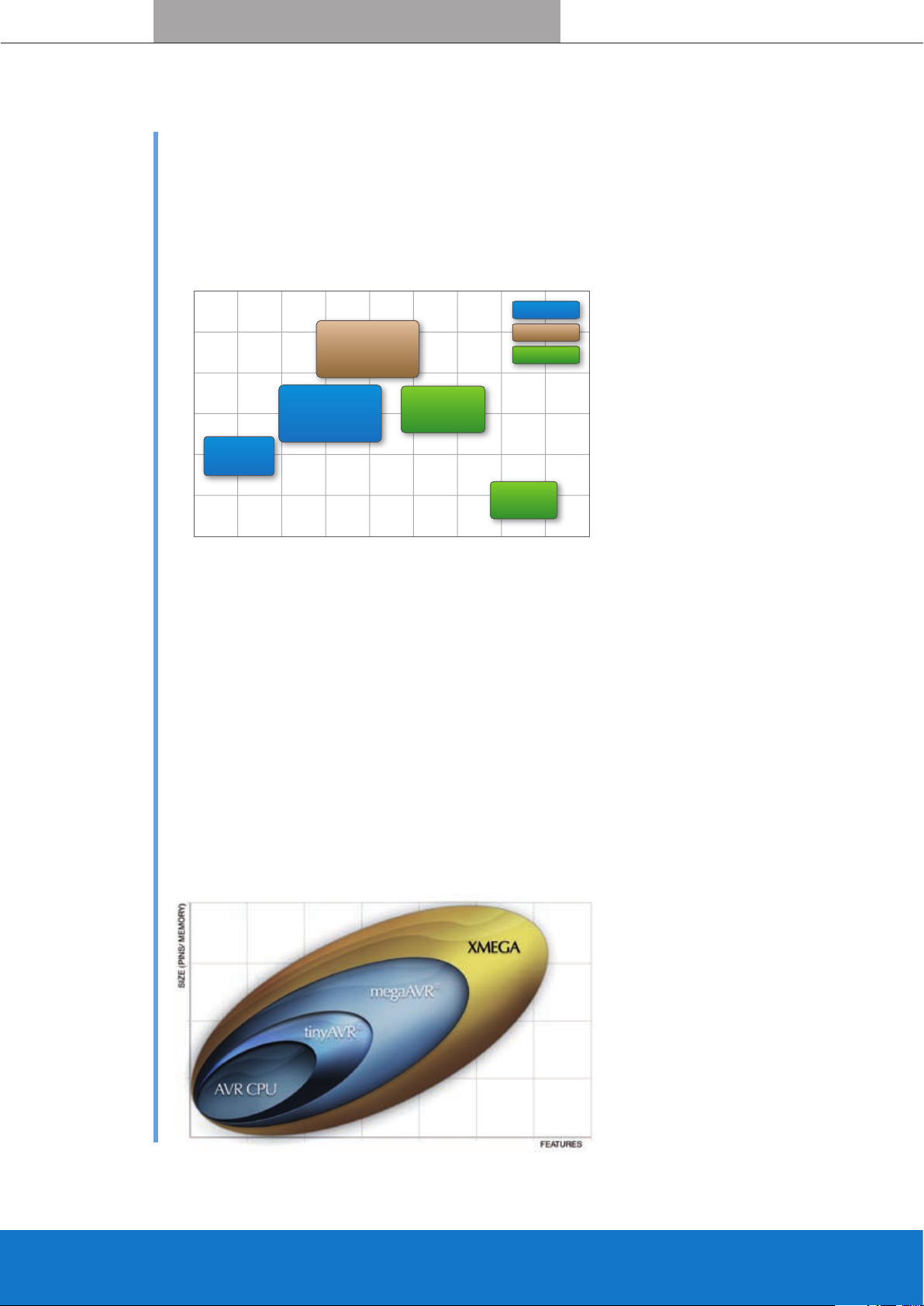
Introducing The AVR Family
High Performance/Low Power 8- to 32-bit microcontrollers/processors
AVR Devices — success through innovation
Atmel® offers both 8-bit and 32-bit AVR®’s, and since day one the AVR philosophy has always been clear:
Highest performance with no power penalty.
Atmel is of feri ng a wide range of AVR
microcontrollers:
tinyAVR , 1-16 KBytes Flash, 8-32 pin
•
packages
megaAVR, 4-256 KBytes Flash, 28 to
•
100 pin packages
AVR XMEGA, 16-384 KBytes Flash,
•
44-100 pin packages
AVR32 UC3, 64-512 KBytes Flash,
•
48-144 pin packages
• AVR32 AP7, 210 DMIPS throughput at
150 MHz, 196-256 pin packages
®
®
AVR XMEGA - For demanding embedded applications
With a DMA Controller, an Innovative Event System, crypto engine and high speed ADC and DAC,
AVR XMEGA™ pushes the boundaries for high performance 8/16 bit MCUs while still remaining highly
®
compatible with tinyAVR
and megaAVR®.
XMEGA highlights
• picoPower™ technology for ultra low power consumption
• True 1.6 volt operation and CPU speeds up to 32 MHz
• Event System and DMA controller
• High speed, high resolution 12-bit ADC and DAC
• Crypto engine, Timers/Counters and fast communication interfaces
• Accurate and flexible Clock System with automatic clock failure protection
All AVR devices from the smallest tinyAVR
to the largest XMEGA uses the same CPU.
They dif fer only in features, pin count and
memor y size. This enable AVR to cover the
complete 8- and 16-bit market with one
single, compatible product family.
Page 3
www.atmel.comwww.atmel.com
CPU
I/O AC ADC
FLASH
WDT
T/C
PIN
CHANGE
INT.
DMA
EVENT
SYS.
TWI SPI USART
ASYNC. CLK
MAIN CLK
CPU
I/O AC ADC
FLASH
WDT
T/C
PIN
CHANGE
INT.
DMA
EVENT
SYS.
TWI SPI USART
CPU
I/O AC ADC
FLASH
WDT
T/C
PIN
CHANGE
INT.
DMA
EVENT
SYS.
TWI SPI USART
ASYNC.
CLK.
MAIN
CLK.
BOD
CPU
I/O AC ADC
FLASH
WDT
T/C
PIN
CHANGE
INT.
DMA
EVENT
SYS.
TWI SPI USART
BOD
CPU
I/O AC
FLASH
WDT
T/C
PIN
CHANGE
INT.
DMA
EVENT
SYS.
TWI SPI USART
ADC
ASYNC.
BOD
CPU
I/O AC ADC
FLASH
WDT
T/C
PIN
CHANGE
INT.
DMA
EVENT
SYS.
TWI SPI USART
ASYNC.
CLK.
MAIN
CLK.
BOD
CPU
I/O AC ADC
FLASH
WDT
T/C
PIN
CHANGE
INT.
DMA
EVENT
SYS.
TWI SPI USART
BOD
CPU
I/O AC
FLASH
WDT
T/C
PIN
CHANGE
INT.
DMA
EVENT
SYS.
TWI SPI USART
ADC
ASYNC.
BOD
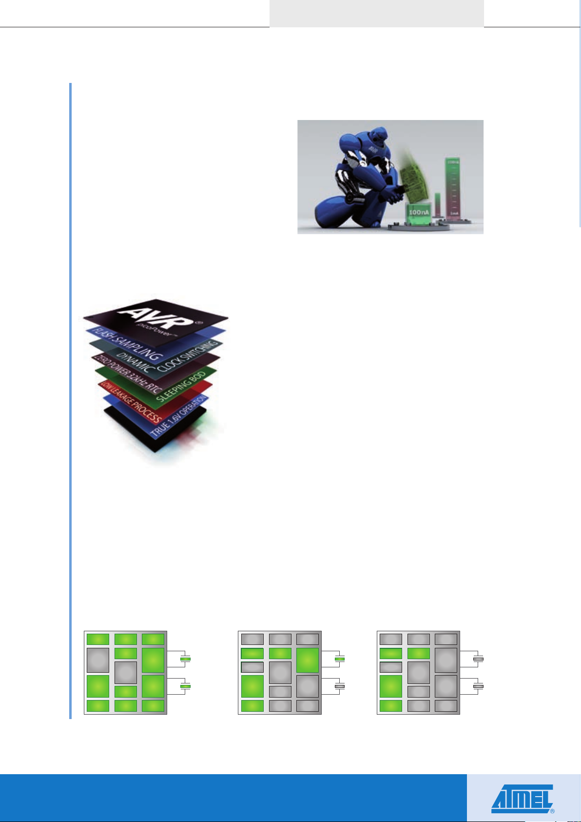
picoPower Technology
Reducing power consumption—maintaining performance
picoPower — Best MCU power budget
Atmel’s picoPower technology reduces power
consumption in both sleep and active mode. With
picoPower technology the embedded designer
can reduce the applications power consumption
while maintaining performance.
True 1.6 Volt Operation
AVR XMEGA offers true 1.6 Volt operation. All functions including ADC, DAC, Flash- and EEPROM
memories are all operating down to 1.6V. This allows safe operation directly from a 1.8V ±10% power
supply. It also enables deeper battery discharge to increase battery life.
Minimized Leakage Current
AVR XMEGA leakage current is only 100 nA while still maintaining
full RAM and register retention. This reduces power consumption
for applications spending most time in sleep mode.
Ultra Low Power 32 kHz Crystal Oscillator
AVR XMEGA’s Real Time Counter consumes only 500 nA while
running from a 32.768 kHz Crystal Oscillator.
Sleep modes
XMEGA has five different sleep modes to turn off unused modules
and reduce the power consumption in the application. Many
sleep modes makes it easy to find the perfect fit for the applica-
tion. The granularity is further enhanced by the innovative Power Reduction Register technology.
In idle sleep mode all peripherals operate while the CPU is sleeping
to reduce the power consumption. with
up to 50%, while event handling, communication and data input/output still run.
In power-save mode, XMEGA uses 650nA to run the Real Time Counter and have full SRAM and register
retention offering industry leading low power numbers. Enabling Watchdog and Brown Out adds only 1uA.
In power-down mode, XMEGA uses only 100nA with SRAM and register retetion, and 5us wake-up time
from pin change on any I/O pin and TWI address match.
Standby and extended standby sleep modes are identical to power-down and power-save, except the
external oscillator is kept running to reduce wake-up time.
Idle mode
Power-save mode Power-down mode
Page 4
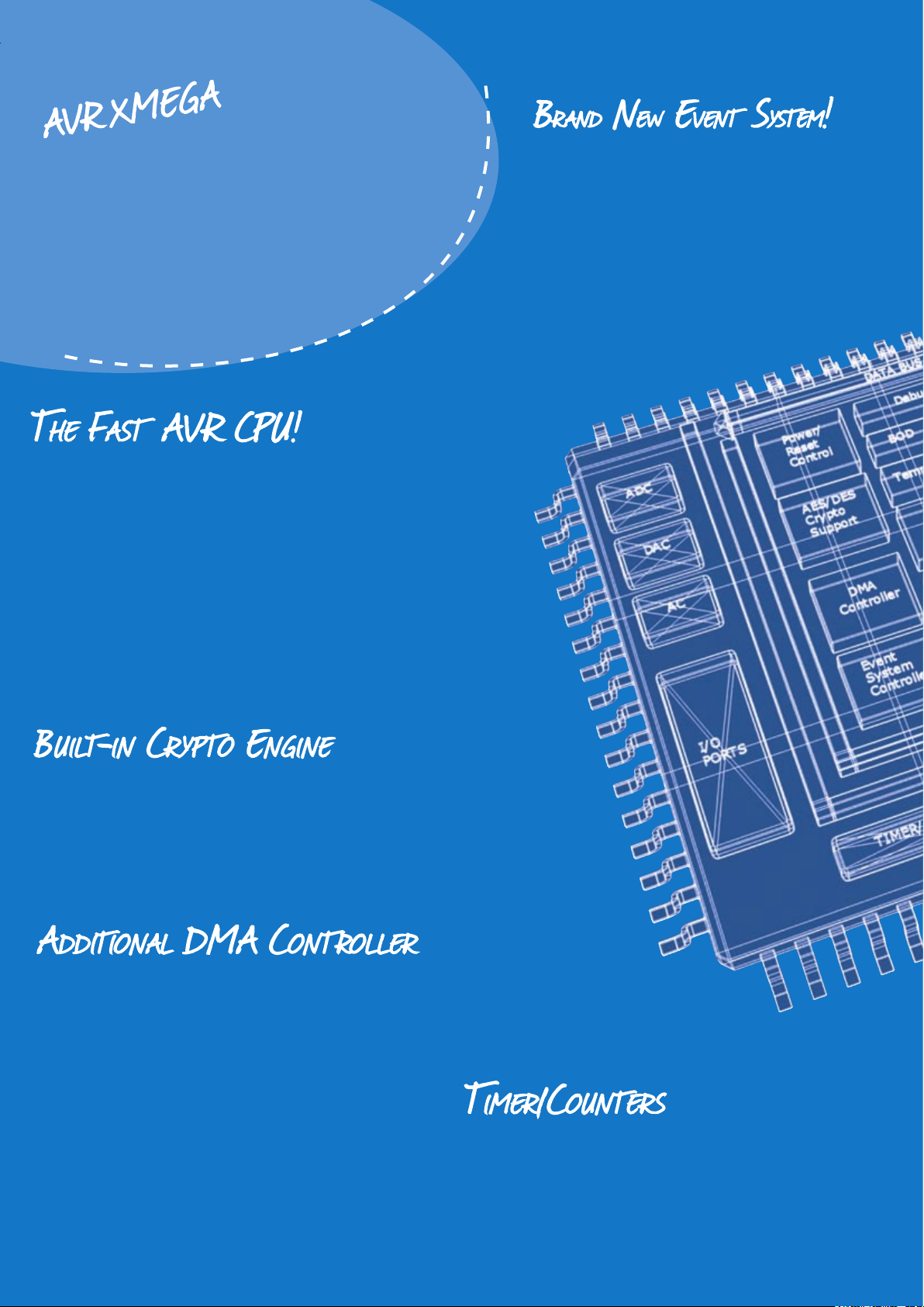
The new XMEGA microcontrollers feature
- Off-loads the CPU
- Based on the AVR CPU
- Increased CPU speed -> 32 MHz
- Supports ultralow 1.6 Volt operation
- Reduced power consumption
- Up to 32 MIPS
- Single cycle execution
- Instruction set optimized for C
- 32x8 general purpose registers
- hardware multiplier
- Reducing power usage
- Up to 8 simultaneous events
-> 100% predictable response time
-> Perfect for 8/16-bit applications
- Supports both AES and DES
- Reducing CPU time and power consumption
- Minimal CPU overhead for secure communication
- Off-loads the CPU
- Saves power
- 4-channels
-> Fast transfer between memories
and peripherals
- 16-bit (32-bit cascaded)
- Advanced Waveform eXtensions
- 16-bit RTC
Page 5

XMEGA includes a programmable and sampled BOD and a low
power, CPU independent Watch-dog timer.
XMEGA has flexible I/O pin conguration, sensing, and wake-up
signaling plus programmable multi-level interrupt Controller
- Internal 32 kHz, 2 MHz, 32 MHz + PLL
- 1% accuracy
- External oscillator or clock input
- Dynamic and safe clock switching
- 1x - 2048x prescaling
- Short wake-up from sleep modes
- FAST and SECURE!
- Up to 384 KB FLASH
- Up to 4 KB EEPROM
- Up to 32 KB SRAM
- 12-bit resolution
- 2 Msps ADC
- 1 Msps DAC
- analog comparator
- USART + SPI + Two-Wire Interface (I2C compatible)
- External Bus Interface
- Debugging/Programming
Page 6

AVR XMEGA™ MICROCONTOLLERS Everywhere You Are
ALU
32 General
Purpose
Registers
C Source:
unsigned char *var1, *var2;
*var1++ = *--var2;
Generated assembly code:
LD R16, -x
ST z+, R16
®
System Performance
For Embedded systems, system performance is much more than a good MIPS number. It is important to
have powerful peripherals and features that allow the application to run smoothly with minimum power
consumption.
AVR CPU and Instruction Set
Auto increment /Decreme nt example
The AVR XMEGA uses the AVR RISC CPU which is
created for high level C code development. The instruc
tion set and CPU design are tuned for minimum code size
and maximum execution speed. Due to the true single
cycle execution of arithmetic and logic operations, AVR
microcontrollers perform close to 1 MIPS per MHz.
-
Central in the AVR architecture is the fast-access register file with 32 x 8-bit
general purpose working registers directly connected to the Arithmetic Logic
Unit. Within a single clock cycle the ALU can be fed two arbitrary registers, do a
requested operation, and write back the result.
The AVR XMEGA instruction set also support atomic 16-bit register access,
32-bit arithmetics, and have three 24-bit memory pointers.
Event System
The innovative AVR XMEGA Event System allow peripherals to send signals (events) directly to other peripherals
without involving the CPU. This ensures short and 100% predictable response time and at the same time
offloads the CPU.
Without Event System all Peripheral Requests need to be handled
by the CPU.
With Event System peripherals can send signals (events) to other
peripherals.
Page 7

www.atmel.com
ADC
12-bit Compare
Function
VREF
DAC
TEMP. SENSOR
8 - 16 External
Pin Inputs
4 x 8 External
Dierential
Pin Inputs
Gain stage
1-64x
DES
8 bytes data
8 bytes key
16 clock cycles
8 bytes cipher
AES
16 bytes data
16 bytes key
375 clock cycles
16 bytes cipher
Data
Secure Data
DMA Controller
The AVR XMEGA’s 4-channel Direct Memory
100% CPU us age
withou t DMA
with DM A
Access (DMA) Controller enables fast, CPU
independent data transfer between any locations
in the data memory space and the peripherals.
MSB
Commu nicati on rate
Flexible channel priority selection, several address-
ing modes and double buffering capabilities. The DMA Controller a powerful module for all data oriented
applications such as signal processing and industrial control. Each DMA transfer can range from 1 byte to
16 Mbytes, increasing CPU computing performance and lowering power consumption.
CPU load at various communication spe eds
SPI
(kbp s)
250 0 % 8 % 19.2 0 % 1 %
500 0 % 16 % 116.2 0 % 3 %
with DMA No DMA
1 1 % 30 % 921.6 1 % 26 %
2 1 % 57 % 1.2 1 % 34 %
4 2 % 98 % 2 1 % 58 %
UART
(kbp s)
with DMA No DMA
Crypto Engine
AVR XMEGA includes a crypto engine for 64-bit DES and 128-bit
AES encryption and decryption.
There are no export limitations for the AVR XMEGA with crypto
engine, so using XMEGA for crypto function do not limit where you
can sell your product.
Analog and Digital Conversion
AVR XMEGA is highly integrated
with high performance 12-bit
ADC and DAC. The ADC sup-
port up to 2 million samples
per second. The DAC has con-
version rates up to 1 msps and
comes with built-in offset and
gain compensation. XMEGA
also include several analog
comparators with window func-
tion and flexible input selection.
Page 8

AVR XMEGA™ MICROCONTOLLERS Everywhere You Are
Automatic
Calibration
Internal
Clock
Sources
External
Clock
Sources
High
Frequency
PLL
Prescaler
Block
Reference
clk
CPU
clk
PER
clk
PER2
clk
PER4
clk
RTC
High-level
Medium-level
Low-level
Program Flow and Interrupt execution
1
2
3
4
5
1 2 3 4 5
Main
Main
Main
HOLD
HOLD
High-level
Medium-level
Program Flow and Interrupt execution
1
1
2
3
4
1 2 3 4
Main
Main
Main
Medium-level
HOLD
HOLD
07
®
Clock System
AVR XMEGA’s clock system allow flexible change of frequency. Dynamic Clock Switching allows the Embedded
Designer to tune performance and power consumption to fit the application. The internal PLL and prescaler
can be used to scale the clock sources dynamically up or down to further match application requirements.
With a built-in External Oscillator failure detection and internal RC oscillator with ± 1% accuracy over tempera-
ture and voltage, XMEGA offers the most safe, reliable and flexible clock system.
Input and Output
AVR XMEGA offers flexible I/O pin configuration with various sensing,
wake-up, synchronous/asynchronous, and driver settings. I/O pin’s
direction, value and logic state are read through separate registers.
The optional Slew-Rate limitation reduces EMI. Virtual ports regis
ters allow single cycle pin manipulation. This makes software for
bit-banging smaller and faster.
Interrupt Controller
AVR XMEGA include a multi level interrupt controller. Three priority
levels are supported, where higher level interrupts are prioritized and
executed before low level interrupts. All peripherals can be assigned
any interrupt level.
-
A higher level inte rrupt will halt execution of a lower level interrupt
routine. The lower level interr upt routine wil l continue and finish
after the highe r level interrupt routine finishes.
A second interrupt at an interrupt level already being ser vice d, will
pend until the first interrupt routine finishes.
Page 9

www.atmel.com
CNT
BOT
MAX
"update"
PER
CNT written
DIRECTION
CNT
MAX
New Period writtento
PERBUF that is higher
than current CNT
New Period writtento
PERBUF that is lower
than current CNT
"update"
"write"
New PER is updated
with PERB UF value.
BOT
DTI CNT
T/C output
high side output
low side output
t
low side
t
high side
T
events
CNT
PER
BOT
Capture 0 Capture 1 Capture 2 Capture 3
"capture"
Period (T)
external signal
events
CNT
MAX
BOT
"capture"
Timer/Counter
Base Counter
Timer Period(PER)
Counter(CNT)
Logic Control
Compare/Capture Channel n
Capture Control
Waveform
Generation
Comparator
Buer
AWeX
Dead-Time
Insertion
Pattern Generator
Fault Protection
clk
PER4
Hi-Res
Ports
clk
PER
Prescaler
Event System
Interfaces
AVR XMEGA comes with various interfaces that combined with DMA or Event System creates a powerful and
fast communication platform.
USART
Full asynchronous and clocked synchronous
operation.
• Fractional BAUD Rate Generator
• Master SPI mode
• IRCOM module for IrDA Compliance
EBI
External Bus Interface, for easy access to
• SRAM
• SDRAM
• External peripherals (e.g. LCDs)
• Memory mapped devices
• Up to 4 Mbps communication
TWI (The Two Wire Interface)
SPI
Fast full duplex synchronous serial communication
• Master and Slave Operation
• Up to 16 Mbps communication
Bi-directional 2-wire bus communication,
2
• I
C and SMBus compliant
• Slave operates in all Sleep Modes
• Full 100 kHz and 400 kHz support
• Master and Slave operation
Timer/Counters
All AVR XMEGA Timer/Counter modules are 16-bit with Input
Capture and Pulse Width Modulation (PWM) functionality. Up
to 128 MHz PWM is possible from internal PLL by using the Hi-
Res extension. Using the Event System and Advanced Waveform
Extension (AWeX) and high resolution extention, implementation of
advanced motor control (AC, BLDC, SR, and Stepper) and power
control applications is made easy.
Normal mode of ope ration, counting up or down
Changi ng the period with buffering in dual slope mode
AWeX Dead Time Inser tion (DTI) with separate high side and
low side period
Input capture of pin change using the Event System
Frequency capture of an external signal
Page 10

www.atmel.com
Ease of use
AVR XMEGA microcontrollers benefit from the already existing AVR tools- and software chain. With a large
ecosystem including hardware, software, documentation, and partners available, embedded developers
will find it easy to succeed with the XMEGA!
AVR Tools — quality and low cost
Debugging and Programming
All XMEGA devices include a non-intrusive On-Chip Debug system that requires no device resources.
This gives real time access to all peripheral registers, data and program memories, and support unlimited
number of break points. XMEGA has a fast, serial programming interface for production line- or in system
programming. Using a bootloader XMEGA can receive flash upgrades in the field through any interface
without reset or halt of critical program execution. The crypto engine and a serial number in each device
ease implementation of safe crypto bootloaders, networking applications, authentication and life cycle
product tracking.
AVR Documentation and Software — ready, steady, go!
With both devices and tools available designers need good documentation. From the smallest devices to
the largest processors, reference datasheets describing features and use are available from the Atmel web
pages. Free application notes and library with complete code make it easy to start development. Partner
software brings your product to the market with no hassle.
Support
On our dedicated MCU pages you can easily submit questions and get technical support. All relevant AVR
XMEGA FAQs, datasheets, application notes, and software are also available online:
http ://www.atmel.com/avr
Selection Guides, Data Sheets and Errata Sheets
Application Notes and Reference Librar y
Atmel and Third Par ty Tools
Software, User Guides
Consultants, Distributors and Atmel Representatives
http ://support.atmel.no
Official Atmel MCU technical suppor t center with FAQ and
email notification ser vice
http ://www.avr tv.com
Official AVR podcasts
http ://www.avrfreaks.net
AVR Experts Discussion Forum, Selection Guides for Tools and
Products, Third Party Tools Information, FAQs
Page 11

AVR XMEGA™ MICROCONTOLLERS Everywhere You Are
011
®
The XMEGA Product Range
All AVR XMEGA are pin and 100% code-compatibility across all devices from the smallest to the largest.
It is possible to development with any XMEGA device, and switch to any other XMEGA device later without
having to change any code. It enables companies to keep and maintain only one code base and use and
re-use this across multiple projects. The result is a much faster development and prototyping cycles.
• Operating voltage form 1.6 to 3.6V
• CPU speed up to 32 MHz
• 16 to 384 Kbytes of Internal Flash Memory
• 100% code compatibility
• Pin compatibility
• Easy to migrate between XMEGA devices
• 44 to 100 pin packages
Produc t (a)
ATxmega64A1
ATxmega128A1
ATxmega192A1
ATxmega256A1
ATxmega384A1
ATxmega64A3
ATxmega128A3
ATxmega192A3
ATxmega256A3B
ATxmega256A3
ATxmega16A4
ATxmega32A 4
ATxmega64A4
ATxmega128A4
ATxmega64D3
ATxmega128D3
ATxmega192D3
ATxmega256D3
ATxmega16D4
ATxmega32D4
a) Al l XMEGA devices ha ve Event Sys tem channels, an d tempera ture range from -40 °C to +85°C and 32 MHz, 2 MHz and 32 KHz cal ibrated PC oscill ators.
b) F: Futu re produ ct, I: De vice un der Introduction.
c) Pb-free packaging alternati ve, complies to the European Directive for Restrictio n of Hazardou s Substances (RoHS directive). Also Halide free and fully Green.
d) Include Bat tery b ackup f uncti on
For sam ples an d pric ing offer, plea se cont act you l ocal di stributor or A tmel sa les re pres entat ive. ht tp: //www.atm el.com/contac ts/
Status (b)
Flash ( KB)
Boot code (By tes)
EEPROM ( KB)
SRAM ( KB )
DMA (c hanne ls)
Event (Channels)
I/O p ins
16-bit Timers
PWM (channel)
RTC 16-bit
RTC 32-bit ( d)
SPI
TWI ( I2C)
USART
12-bit ADC ( ch.)
12-bit DAC (ch.)
Analo g Comp.
Interr upts
Interr upts Ext.
Vcc Range (V)
Clock Speed
I 64 4 2 4 4 8 78 8 24 Y 4 4 8 2x8 2x2 4 122 78 1.6 - 3.6 32 TQFP100, BGA100
(MHz )
I 128 8 2 8 4 8 78 8 24 Y 4 4 8 2x8 2x2 4 122 78 1.6 - 3.6 32 TQFP100, BGA100
I 192 8 4 16 4 8 78 8 24 Y 4 4 8 2x8 2x2 4 122 78 1.6 - 3.6 32 TQFP100, BGA100
I 256 8 4 16 4 8 78 8 24 Y 4 4 8 2x8 2x2 4 122 78 1.6 - 3.6 32 TQFP100, BGA100
I 384 8 4 32 4 8 78 8 24 Y 4 4 8 2x8 2x2 4 122 78 1.6 - 3.6 32 TQFP100, BGA100
I 64 4 2 4 4 8 50 7 22 Y 3 2 7 2x8 1x2 4 102 50 1.6 - 3.6 32 TQFP64, Q FN64
I 128 8 2 8 4 8 50 7 22 Y 3 2 7 2x8 1x2 4 102 50 1.6 - 3.6 32 TQFP64, QFN64
I 192 8 4 16 4 8 50 7 22 Y 3 2 7 2x8 1x2 4 102 50 1.6 - 3.6 32 TQFP64, QFN64
I 256 8 4 16 4 8 49 7 22 Y 2 2 6 2x8 1x2 4 102 49 1.6 - 3.6 32 TQFP64, Q FN64
I 256 8 4 16 4 8 50 7 22 Y 3 2 7 2x8 1x2 4 102 50 1.6 - 3.6 32 TQFP64, QFN64
F 16 4 1 2 4 8 34 5 16 Y 2 2 5 1x12 1x2 2 77 34 1.6 - 3.6 32 TQFP44, QFN44
F 32 4 1 4 4 8 34 5 16 Y 2 2 5 1x12 1x2 2 77 34 1.6 - 3.6 32 TQFP44, QFN44
F 6 4 4 2 4 4 8 34 5 16 Y 2 2 5 1x12 1x2 2 77 34 1.6 - 3.6 32 TQFP44, QFN44
F 128 4 2 8 4 8 34 5 16 Y 2 2 5 1x12 1x2 2 77 34 1.6 - 3.6 32 TQFP44, QFN44
F 6 4 4 2 4 4 50 5 18 Y 2 1 3 1x16 2 67 50 1.6 - 3.6 32 TQFP64, QFN64
F 128 8 2 8 4 50 5 18 Y 2 1 3 1x16 2 67 50 1.6 - 3.6 32 TQFP64, QFN6 4
F 192 8 2 16 4 50 5 18 Y 2 1 3 1x16 2 67 50 1.6 - 3.6 32 TQFP64, QFN64
F 256 8 4 16 4 50 5 18 Y 2 1 3 1x16 2 67 50 1.6 - 3.6 32 TQFP64, QFN64
F 16 4 1 2 4 34 4 14 Y 2 1 2 1x12 2 55 34 1.6 - 3.6 32 TQFP44, QFN44
F 32 4 1 4 4 34 4 14 Y 2 1 2 1x12 2 55 34 1.6 - 3.6 32 TQFP44, QFN44
Package (c)
Pins/packages
AVR XMEGA is delivered in different package options, including fully green versions.
TQFP-44
QFN-44
TQFP-64
QFN-64
TQFP-100
BGA-100
Page 12

Headquarters
Atmel Corporation
2325 Orchard Parkway
San Jose, CA 95131, USA
Tel: 1(408) 441-0311
Fax: 1(408) 487-2600
International
Atmel Asia
Room 1219
Chinachem Golden Plaza
77 Mody Road Tsimhatsui
East Kowloon
Hong Kong
Tel: (852) 2721-9778
Fax: (852) 2722-1369
Atmel Europe
Le Krebs
8, Rue Jean-Pierre Timbaud
BP 309, 78054
Saint-Quentin-en-Yvelines Cedex
France
Tel: (33) 1-30-60-70-00
Fax: (33) 1-30-60-71-11
Atmel Japan
9F, Tonetsu Shinkawa Bldg.
1-24-8 Shinkawa
Chuo-ku, Tokyo 104-0033
Japan
Tel: (81) 3-3523-3551
Fax: (81) 3-3523-7581
Literature Requests
www.atmel.com/literature
Website
www.atmel.com
© 2008 Atmel Corporation. All rights reserved.
Atmel®, logo and combinations thereof, AVR®, AVR Studio®, “Everywhere You Are®”, STK® and others are registered trademarks, picoPower™, XMEGA™ and others are trademarks of Atmel Corporation or its subsidiaries. Other terms and product
names may be trademarks of others.
Rev.: 7925C-AVR-10/08/10M
Disclaimer: The information in this document is provided in connection with Atmel products. No license, express or implied, by estoppel or
otherwise, to any intellectual property right is granted by this document or in connection with the sale of Atmel products. EXCEPT AS SET
FORTH IN ATMEL’S TERMS AND CONDITIONS OF SALES LOCATED ON ATMEL’S WEB SITE, ATMEL ASSUMES NO LIABILITY WHATSOEVER AND DISCLAIMS ANY EXPRESS, IMPLIED OR STATUTORY WARRANTY RELATING TO ITS PRODUCTS INCLUDING, BUT NOT
LIMITED TO, THE IMPLIED WARRANTY OF MERCHANTABILITY, FITNESS FOR A PARTICULAR PURPOSE, OR NON-INFRINGEMENT. IN
NO EVENT SHALL ATMEL BE LIABLE FOR ANY DIRECT, INDIRECT, CONSEQUENTIAL, PUNITIVE, SPECIAL OR INCIDENTAL DAMAGES
(INCLUDING, WITHOUT LIMITATION, DAMAGES FOR LOSS AND PROFITS, BUSINESS INTERRUPTION, OR LOSS OF INFORMATION)
ARISING OUT OF THE USE OR INABILITY TO USE THIS DOCUMENT, EVEN IF ATMEL HAS BEEN ADVISED OF THE POSSIBILITY OF
SUCH DAMAGES. Atmel makes no representations or warranties with respect to the accuracy or completeness of the contents of this
document and reserves the right to make changes to specifications and product descriptions at any time without notice. Atmel does not
make any commitment to update the information contained herein. Unless specifically provided otherwise, Atmel products are not suitable
for, and shall not be used in, automotive applications. Atmel’s products are not intended, authorized, or warranted for use as components
in applications intended to support or sustain life.
Printed on pa per originated
from durab ly managed fores ts.
Control lin e number CTBA/ 06-00743
 Loading...