

Atmel AVR ICE 200 User Manual

ICE 200
.............................................................................
User Guide


AVR ICE 200 User Guide i
Table of Contents
Section 1
Preface – Read this First......................................................................1-1
1.1 About this Manual ........... ...... ....... ...... .......................................................1-1
1.2 Helpful Information....................................................................................1-1
1.3 Tips ...........................................................................................................1-1
1.4 Checklists..................................................................................................1-1
1.5 Related Documentation ............................................................................1-1
Section 2
Introduction...........................................................................................2-1
2.1 ICE 200 Features......................................................................................2-2
2.2 ICE 200 Contents......................................................................................2-2
2.3 System Requirements...............................................................................2-3
2.3.1 Hardware Requirements.....................................................................2-3
2.3.2 Software Requirements......................................................................2-3
2.3.3 Operating Conditions..........................................................................2-3
2.3.4 Host Interface .....................................................................................2-3
Section 3
General Description..............................................................................3-1
Section 4
Using the ICE 200.................................................................................4-1
4.1 Target Hardware Requirements................................................................4-1
4.2 Power and Signal Operating Conditions...................................................4-1
4.3 Clock Driver Requirements.......................................................................4-2
4.4 Personality Adapters.................................................................................4-3
4.5 Special Tiny12 Personality Adapter Settings............................................4-6
4.6 Connecting to the Target Application........................................................4-7
4.6.1 Checklist.............................................................................................4-9
4.7 Configuration...........................................................................................4-10
4.8 Quick Start ..............................................................................................4-10
4.8.1 Checklist...........................................................................................4-11

Table of Contents
ii AVR ICE 200 User Guide
4.9 Emulator Options Settings......................................................................4-11
4.9.1 Device Settings... ...... ...... ....... ...... ....... ...... ....... .................................4-11
4.9.2 Clock Selection Settings...................................................................4-11
4.9.3 Single-step Timers Setting ........................................................ ...... .4-11
4.9.4 EEPROM Restore Setting ................................................................4-12
4.9.5 Communication Speed Setting.........................................................4-12
4.9.6 Reset Pin Setting (ATtiny12 only).....................................................4-12
Section 5
Special Considerations.......... ..... ............................ ..... .... ..... ................5-1
5.1 External RESET........................................................................................5-1
5.2 SLEEP Instruction.....................................................................................5-2
5.3 Watchdog Timer (WDT)............................................................................5-2
5.4 EEPROM ..................................................................................................5-3
5.5 I/O Port Access.........................................................................................5-3
5.6 16-bit I/O Access (Timer 1 and A/D Converter) ........................................5-4
5.7 UART Data Register .................................................................................5-4
Section 6
Appendix...............................................................................................6-1
6.1 Emulating AT90S1200 and ATtiny10/11...................................................6-1
6.1.1 Using the Include Files .......................................................................6-1
6.1.2 Using the ATtiny12 Adapter for Emulating the ATtiny10/11...............6-2
6.1.3 Using the AT90S2313 Adapter for Emulating the AT90S1200...........6-2
6.2 AVR Emulator Chip Errata ........................................................................6-2
6.3 Troubleshooting ........................................................................................6-3
6.3.1 Feedback and Support .......................................................................6-3
6.4 Contact Information...................................................................................6-3

AVR ICE 200 User Guide 1-1
Section 1
Preface – Read this First
1.1 About this
Manual
This user guide serves as a reference manual for the Atmel AVR® ICE 200™ in-circuit
emulator. The AVR ICE 200 User Guide is an easy introduction on how to use the ICE
200, and a detailed refer ence for adva nced users . Throughout the manual, many references to the AVR microcontrollers are made in short form, i.e. AT90S2313 is referred to
as S2313 and so on.
The user shoul d install th e latest ver sion of the AV R Studio ava ilable on the Atmel
web site.
1.2 Helpful
Information
This manual contains helpful information to improve the reliability, performance, and
longevity of the ICE 200 and the target system.
NOTICE
!
This is a Notice...
Please follow the instructions in a NOTICE carefully.
1.3 Tips Some sections contai n useful ti ps for us ing the ICE 2 00. All the ti ps are em phasi zed as
shown in the example below.
©
Tip! This is a tip!
1.4 Checklists When the detailed descrip tions in the
Connecting to the Target Applicatio n
and in the
Configurat ion
sections have been used and you are beginning to feel comfortable with
the use of the ICE 20 0, you can use the c heckli sts at th e end of the se secti ons for fa st
setup of a new project. The checklists are of great help for getting the debugging system
online without pro blems. Ho wever, novi ce user s should also ch eck that the opera ting
conditions of the target system are compliant to the requirements of ICE 200. This is
described in the
Using the ICE 200
section.
1.5 Related
Documentation
The Atmel CD-ROM contains various documentation relating to the use of AVR microcontrollers and of the debugging tools including AVR Studio User Guide, AVR
Assembler User Guide and complete microcontroller datasheets.
Rev. 1413A-06/23/99

Preface – Read this First
1-2 AVR ICE 200 User Guide

AVR ICE 200 User Guide 2-1
Section 2
Introduction
The ICE 200 in-circuit emulator provides an easy way of debugging embedded systems
that utilizes the Atmel AVR microcontroller. It emulates 11 different devices of the AVR
and the Tiny AVR families.
The philosophy of the ICE 200 is to provide an easy-to-use debugging platform, with a
minimum of differences between the emulator and the actual processor it is emulating.
The AVR emulator chip used by the ICE 200, is produ ced in the same proce ss techno logy as the microcontroller it is emulating. This provides identical electrical
characteristics . On- board d ebugging reso urces ensur e non-intr usiv e softwa re emulation. The ICE 200 hardware also includes an automatic configuration system that makes
the process of connecting the target to the emulator an easy task.
Figure 2-1.
The ICE 200 Components
When used with the AVR Studio debugging environment, the ICE 200 gives the user full
run time control, un limited n umber of break points, symbo lic d ebuggi ng and full memo ry
and register visibility. Multiple ICE 200 emulators can be used by AVR Studio at the
same time, only limited by the number of serial ports available, giving a high degree of
flexibility.

Introduction
2-2 AVR ICE 200 User Guide
2.1 ICE 200 Features ■ Devices Supported
ATtiny12, AT90S 2313, AT90S 2333/4433, AT 90S4414/85 15, AT90S4434 /8535,
ATtiny10/11 (using ATtiny12 adapter), AT90S1200 (using AT90S2313 adapter)
■ Supports 8 MHz (+4.0V to +6.0V) AVR Emulator Chip (varies between devices
being emulated)
■ Wide Target Voltage Range (+2.7V to +5.5V)
■ Emulator Chip Provides Excellent AC Characteristics
■ Non-intrusive
■ Target Voltage Sensing Ensures Secure Operation
■ Personality Adapter for Each of the Supported Processors
■ 32-bits Cycle Counter
■ I/O Continues to Operate in Halt State After a Break or Breakpoint
■ Single-stepping or Continuous Timer Operation while Single-stepping Code. Utilizes
the AVR Studio Debugging Environment that adds: Full Run Time Control: run, break,
trace into, step over, step out, run-to-cursor, reset, autostep and multistep
■ Unlimited Number of Breakpoints
■ Symbolic Debugging Support
■ Full Visibility of and Access to register File, SP, PC and Memories
■ Access to all I/O Registers – See Section 5: Special Considerations
■ Auto Log Points – Non-real Time Logging/Watches
2.2 ICE 200 Contents The ICE 200 contains the following items:
■ ICE 200 Main Board, pod and two Flexible Printed Circuit Cables
■ Personality Adapters for:
ATtiny12 (8-pin DIP)
AT90S2313 (20-pin DIP)
AT90S2333/4433 (28-pin DIP)
AT90S4414/8515 (40-pin DIP)
AT90S4434/8535 (40-pin DIP)
■ 9-pin RS232C Cable
■ Atmel CD ROM containing:
AVR data books
Application notes
AVR Studio
AVR Assembler
■ ICE 200 User Guide (this document)
■ Power Cable
■ Diagnostic Adapter for Test Purposes

Introduction
AVR ICE 200 User Guide 2-3
2.3 System
Requirements
2.3.1 Hardware
Requirements
Pentium-class personal computer with the following specifications is recommended:
■ 16M Byte RAM, or more
■ 3M Byte of free hard disk space
■ CD-ROM or Internet access (for software and data books)
■ VGA monitor, or better
■ 16650 Compatible Serial Port (COM port)
2.3.2 Software
Requirements
The following operating systems are currently supported by AVR Studio:
■ AVR Studio v2.00 or later installed. See the Atmel web site (www.atmel.com) for
latest version.
■ Microsoft Windows NT 3.51
■ Microsoft Windows NT 4.0
■ Microsoft Windows 95
■ Microsoft Windows 98
Note:
AVR Studio will be updated to execute new versions of these operating
systems. See AVR Studio User Guide for latest information.
2.3.3 Operating
Conditions
■ Operation Temperature: 0
°
C - 70°C
■ Operating Humidity: 10 - 90% RH (non-condensing)
■ Supply Voltage: +9.0V to +12.0V DC or 9.0V AC
■ Supply Current: 400 mA
NOTICE!
Violating the recommended operating conditions for the ICE 200 might
cause incorrect operation and damage the emulator.
2.3.4 Host Interface RS-232C @ 19200 bps, 1 start-, 8 data- and 1 stop-bit, no parity. 9-pin female
connector.

Introduction
2-4 AVR ICE 200 User Guide
AVR ICE 200 User Guide 3-1
Section 3
General Description
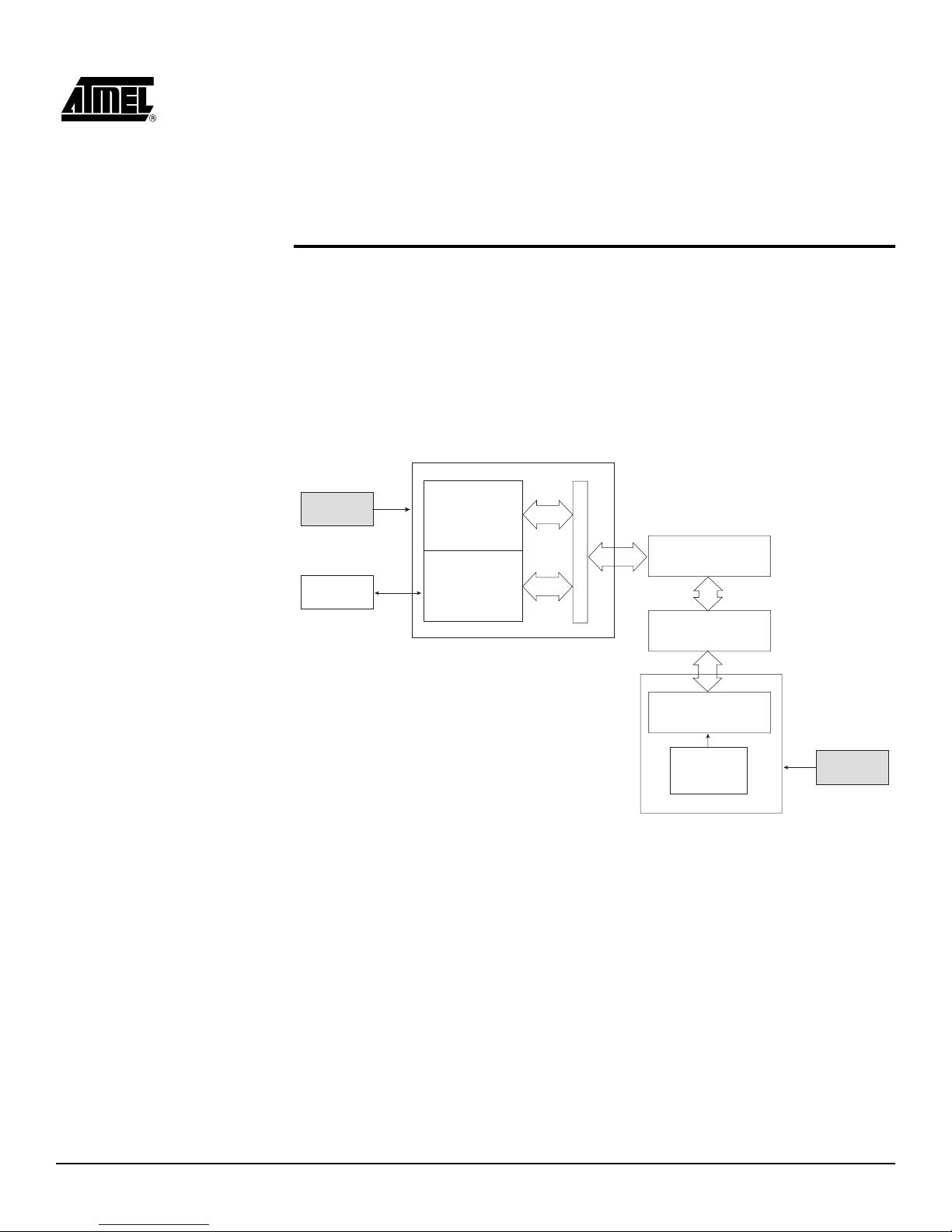
Figure 3-1 shows a simplified block diagram of the ICE 200 connected to a target board
(the application). Power supplies and a host PC are also shown.
Figure 3-1.
ICE 200 – Sim plified Block Diagram
Power
Supply
Host PC
Main Board (5.0V)
Program Memory
Control and
Communication
Logic
Level Converters
POD
(AT90EM04)
Personality
Adapter
Target MCU
Socket
Target Clock
(or XTAL or
Resonator)
Target Board (2.7 - 5.5V)
Power
Supply
FPC
General Description
3-2 AVR ICE 200 User Guide
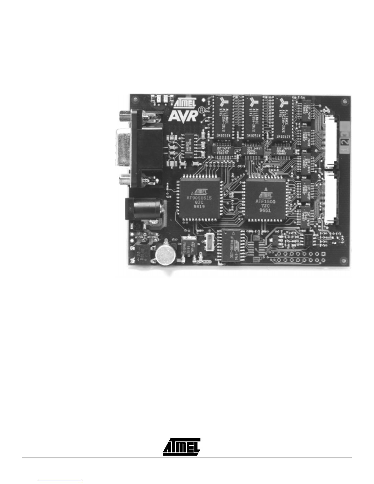
The main board (Figure 3-2) contains the program memory (overlay memory) which
holds the application code that is being emulated. The main board also contains logic for
communicating with the host PC, and the breakpoint lo gic. The level converters allow
the target to operate at a different supply voltage fr om that of the emulator. The level
converters also protect the emulator and the target from being damaged if only one of
them is powered. Due to this feature, a strict power-up sequence is not required.
Figure 3-2.
ICE 200 – Main Board
 Loading...