

Page 1
http://www.BDTIC.com/ATMEL
AVR1508: Xplain training - XMEGA DAC
Features
• Required knowledge
AVR1500: Xplain training – XMEGA™ Basic
AVR1502: Xplain training – XMEGA Direct Memory Access Controller
• Software prerequisites
Atmel
WinAVR/GCC 20100110 or later
• Hardware prerequisites
Xplain evaluation board
JTAGICE mkII
• Estimated completion time
2 hours
1 Introduction
Before starting with this training, it is recommended to do the Atmel XMEGA-Basics
training. For more information about the Atmel XMEGA Digital to Analog Converter
(DAC), please refer to the corresponding data sheet, the Atmel XMEGA Manual
and the AVR1301 application note.
®
AVR® Studio® 4.18 or later
8-bit
Microcontrollers
Application Note
The XMEGA DAC converts digital signals to analog signals. This can be used in
applications where you want stereo sound, signal generation, calibration or signal
compensation.
This training will show how to set up and use the DAC with practical code
examples.
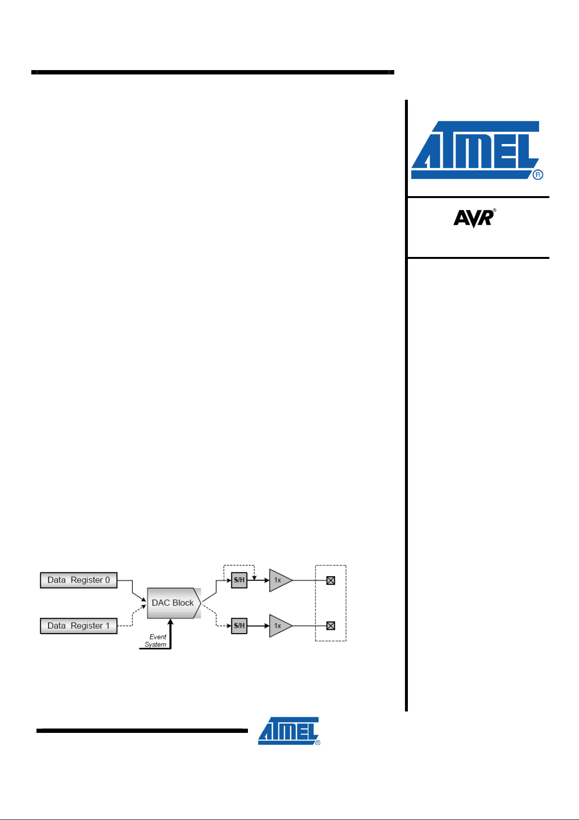
Figure 1-1. DAC Overview
Rev. 8317A-AVR-06/10
Page 2
2 Module Overview
http://www.BDTIC.com/ATMEL
This section provides an overview of the basic configuration options and functionality
of the DAC.
2.1 Conversion Triggers
A DAC conversion can be triggered either by (1) the data registers being written to or
(2) from an incoming event from the Atmel XMEGA Event System.
2.2 Single and Dual Channel Operation
The DAC module contains two data channels with corresponding data registers, but
only one conversion block. The user can choose between using channel 0 as a
continuous-drive output or both channels as two Sample/Hold outputs.
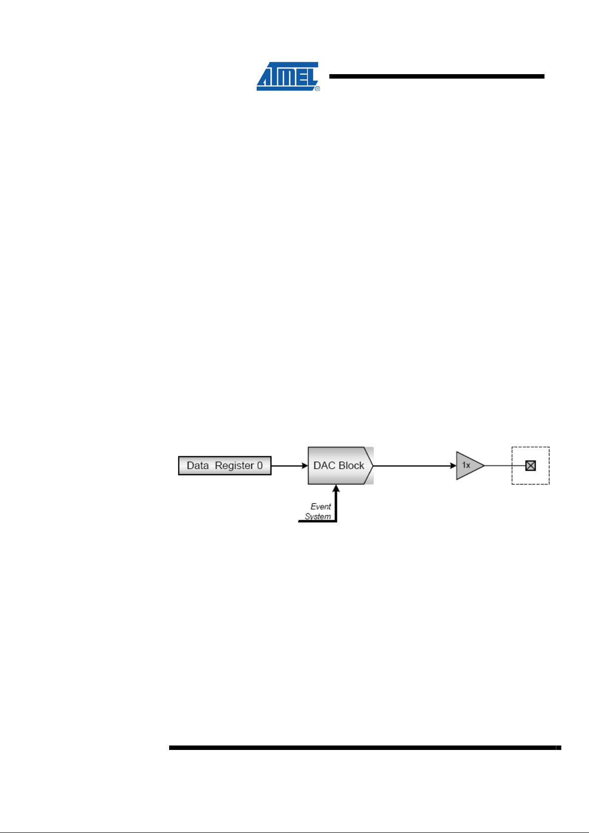
2.2.1 Single Channel Operation
2.2.2 Dual Channel Operation
The channel operation mode is configured with the Channel Select bitfield (
Control Register B (
In Single Channel mod
is always connected to the data registers and the output driver stage of channel 0,
hence the concept continuous-drive output.
Figure 2-1 shows the DAC in single channel op
Hold stage is bypassed compared to Figure 1-1.
Figure 2-1. Single Channel
In dual ch
for channel 0 and 1. Thus, sample and hold blocks are used to keep the output values
between conversions. To be able to maintain a stable output value on the two
outputs, the channels must be refreshed regularly.
ann
CTRLB).
e, only one of the two channels is used. The conversion block
eration mode. Note that the Sample /
Operation
el mode, the DAC conversion block is alternately used to convert values
CHSEL) in
A refresh of the channel means that its value is converted and output again. This is
necessary because the Sample/Hold circuit will lose its analog signal voltage over
time, just like the voltage over a capacitor that is discharging through a parallel
resistor.
Note that a higher refresh rate causes higher power consumption (for details, please
refer to the data sheet).
The sample interval is the time to store (sample) a value for analog output. This is
analogous to charging a capacitor. If the sample time is too long, you may lose
information from signals with high slew rate (steep curved signals). If the sample rate
2
AVR1508
8317A-AVR-06/10
Page 3
http://www.BDTIC.com/ATMEL
is slower than the refresh rate, the DAC module has an internal refresh interval
generator as well. The automatic refresh interval is configured with the Refresh
Timing Control bitfield (
Note that manual conversions or event triggering does not affect the refresh interval.
This means that the channels will be refreshed at constant intervals even if extra
conversions are done in between, caused by for instance a manual update of a data
register.
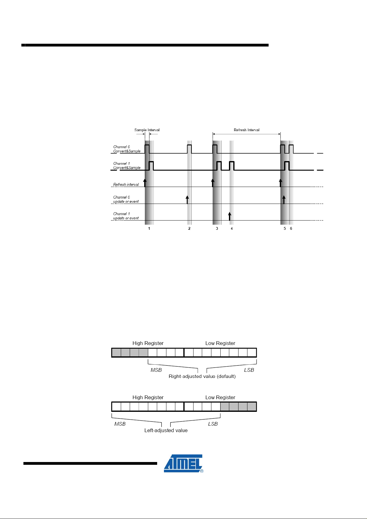
Figure 2-2. Channel refresh and conversion request
REFRESH) in the Timing Control register (TIMCTRL).
AVR1508
Figure 2-2 shows an example. Each sample is done in time int
Sample Interval. After sampling Channel 0, the Channel 1 is sampled, and this may
be repeated if using the automatic refresh feature, see number 1 in the Figure 2-2. If
annel
a ch
the numbers 2, 4 and 6 in Figure 2-2.
2.3 Left and Right Adjusted Values
The Atmel XMEGA DAC module can be configured to accept left adjusted values by
setting the Left-adjust Value bit (LEFTADJ) in Control Register C (CTRLC). Figure 2-3
s the difference between right and left adjusted values in the DAC value
show
registers.
Figure 2-3. Left and Right Adjusted Values
e
rvals; we call it a
conversion is requested, there will be additional updates, for instances, see
8317A-AVR-06/10
3
Page 4

The 12-bit input value to the DAC contains two 8-bit registers, referred to as the high
http://www.BDTIC.com/ATMEL
and low registers. By default, the 12-bit value is distributed with the 8 LSB in the low
register and 4 MSB in the high register.
In some applications, it is useful to work with left-adjusted data. This could be if, for
instance, storing 8-bit data to the DAC and using the high-byte register only (8 MSB).
4
AVR1508
8317A-AVR-06/10
Page 5

3 Overview
http://www.BDTIC.com/ATMEL
This training covers some of the basic Atmel XMEGA DAC features:
Task 1: Single Conversion Mode
This task shows how to set up the DAC in single conversion mode.
Task 2: Dual Conversion Mode
This task shows how to use the DAC in dual conversion mode. With a speaker you
may play dual tones by pressing button switches, like a piano.
Task 3: DAC with Event System
This task shows an example on how to use the event system to trigger DAC
conversions. A speaker will play a pre-recorded track in 8-bit resolution, sampled at
11 kSps.
AVR1508
Task 4: Using the DMA to feed the DAC with data
This task will teach you how to set up the DMA to feed data to the DAC.
Figure 3-1: How the speaker is connected on the Xplain
(cap
As Figure 3-1 shows, we have added a DC filter
each channel. The resistor should be 1 k Ohm minimum and is used as a current
limiter to protect the DAC output. A Texas Instruments TPA253 Class B audio
amplifier is used to drive the speaker in mono mode, where AUDIO_OUT_L and _R
from the XMEGA are internally summed in the amplifier.
acitor of 1 µF) and a resistor to
8317A-AVR-06/10
5
Page 6

4 Task 1: DAC Introduction
http://www.BDTIC.com/ATMEL
This task will introduce you to the DAC and show how to write code to set it up in
Single Conversion mode without using driver functions. We will generate a triangle
wave to the DAC output channel and use the speaker to play the tone of the signal.
The goal for this task is that you know how to:
• Get started with the Atmel XMEGA DAC
• Set up the DAC in Single Conversion Mode
• Generate a triangle wave to play with the speaker
1. In Atmel AVR Studio, open the project
Note that there are three lines of code that set up the DACB:
• The voltage reference
• Single conversion mode
• Enabling of the DACA channel 0
2. Open the Atmel XMEGA A Manual and look through the register description
chapter for the DAC. Compare the CTRLA, CTRLB and CTRLC registers in the
manual with the C-code in
looks correct
3. Build and run the code in AVR Studio and verify that you hear a sound
4. AVCC is chosen as the voltage reference. Which other references could have been
chosen?
5. If you choose for instance INT1V instead of AVCC, what would happen with the
sound?
task1.c. Verify that you understand the code and that it
DAC_Intro.aps and look at the file task1.c
6. Change the value of TRIANGLE_ABRUPTNESS, build and run again
6
AVR1508
8317A-AVR-06/10
Page 7

5 Task 2: DAC in Single Conversion Mode
http://www.BDTIC.com/ATMEL
Single Conversion mode means that we are only using one of the two channels in the
DAC module. In the ATxmega128A1, there are two DAC modules, DACA and DACB.
Each module has two channels. (We will use DACB only in this training.) Note that in
Single Conversion mode, there is no Sample and Hold circuit enabled, thus, the
analog output on the channel is always enabled.
The goal for this task is that you know how to:
• Set up the DAC in Single Conversion Mode using a driver
• Play a pre-recorded sound track to the speaker
AVR1508
1. Open the project
The code in this task is writing a piece of a sound track to the DAC. The sound track
is recorded in advance and the samples are saved in program memory. The sound
track is sampled with 8-bit precision and 11000 samples per second. A timer is set up
to trigger an overflow interrupt service routine (ISR) 11 thousand times each second,
to write samples to the DAC. Your task is to set up the DAC correctly.
2. Try to roughly understand the code in
3. In the main function you will see the empty
call. Open the driver file,
function
4. Insert the three missing parameters. You may use the Atmel XMEGA A Manual
and the
reference and left adjusted result for the channel 0. Why do you think we are using
left adjusted result?
5. In the ISR for the Timer/Counter C0, we want to write to the DAC. Fill in the
missing three parameters
iox128A1.h header file to find the macros to fill in. Hint: Use the AVCC
SingleConversion.aps and take a look at Task2.c
Task2.c
DAC_SingleChannel_Enable function
dac_driver.c, and scroll down to the definition of this
6. Build the project and run the program from debugging mode
7. Press and hold one of the buttons SW0, SW1 or SW2. You should now hear the
sound track playing. If not, you may refer to the solution code and see if you should
change some of your setup
8. When pressing SW0, the TIMER_C0_PERIOD equals 181. Why this value? What
happens when pressing SW1, adding 50 timer ticks?
8317A-AVR-06/10
7
Page 8

6 Task 3: DAC in Dual Conversion mode
http://www.BDTIC.com/ATMEL
In this task we will look into the Dual Conversion mode in more details. As you may
have read from the Introduction chapter, the Dual Conversion mode means that both
of the two channels of a DAC module are used. For instance, this mode could be
used to play stereo music or to generate two different signals on the outputs.
In this task, you will set up the DAC in Dual Conversion mode. You may refer to the
Atmel XMEGA A Manual and the introduction chapter of this document in order to
understand the mode. It is important to understand this operational mode when
setting up the driver.
The program will output the gamut (piano tone scale) on channel 0 in Single
Conversion Mode when pressing the different switches on the Xplain. The task is to
enable Dual Conversion Mode. When you have done that, you will be able to play two
different tones at a time with the XMEGA.
Note that on the Xplain, though we have stereo output, the sound signal is mixed
down to mono outside the Atmel XMEGA as we only have one speaker. Refer to
Figure 3-1 for more details.
The goal fo
• Set up the DAC in Dual Conversion Mode
• Have fun playing the piano with dual-tones on the Xplain
1. Open the project
understand the main function and the ISR-routine for the Timer C0. As you will see,
we are going to output square signals to the DAC
2. Compile and run the program. Press the switches and play a song
3. Break the execution of the program
4. In the main function, replace the
DAC_DualChannel_Enable function. Open the dac_driver.c and fill in the missing
parameters. Note that only the two last parameters are new
Open the XMEGA A Manual and the header file
parameters that may fit in the
options; is it for instance possible to turn off the automatic refresh rate?
r this task is tha
DualConversion.aps and take a look at Task3.c. Try roughly to
t you know how to:
DAC_SingleChannel_Enable function with the
iox128A1.h to find out which
DAC_DualChannel_Enable function. Think about the
5. Build and run the program. What happens if you play the piano on the Xplain now?
(Answer: Dual tones)
8
AVR1508
8317A-AVR-06/10
Page 9

7 Task 4: Using the DMAC to feed the DAC
http://www.BDTIC.com/ATMEL
In this task we will use the DMA Controller to write a Sine Wave to the Digital to
Analog Converter. When using the DMAC, the CPU will be unloaded and we could in
fact do other operations while the sine is being converted.
Your job will be to set up the second DACB channel (channel 1) and set up a working
configuration for the DMAC. It could be an advantage to have done the DMAC
training in advance.
The goal for this task is that you know how to:
• Set up the DAC in Dual Conversion Mode
• Set up the DMAC to write data to the DAC
• Get more familiar with the DMAC in a practical example
4500
4000
3500
3000
2500
2000
1500
1000
500
AVR1508
0
12 3 4 5 6 78 910111213141516171819202122232425262728293031323334353637383940
Series1
1. Open the project
DMA_Approach.aps and take a look at Task4.c. Try to roughly
understand the code. We are going to output sine wave signals to the DAC using
the DMAC
2. In the
main()-function, we have set up the DAC channel 0 for you. Complete with
code for the DAC channel 1 by inserting the missing parameters in the function call
DMA_Setup()
3. Some of the code inside the
DMA_Setup() function is missing, too. By using the
hints below, insert the missing code
Hints:
There are missing codes for the source data, which are the hard coded sine wave
and the destination (DAC). The DMA will only send one byte at a time, but the data to
send is of the type
uint16_t. The destination should therefore be bursts of two bytes.
The source data should be repeated blocks of the size of the sine wave.
4. Build and run the project. You should now hear two different tones on the two DAC
channels
8 Summary
Here are some of the highlights from this training:
• Using DAC to transfer in Single Conversion Mode
• Using DAC to transfer in Dual Conversion Mode
• Using DAC to play the piano
• Using DMAC to feed the DAC without using the CPU
8317A-AVR-06/10
9
Page 10

9 Resources
http://www.BDTIC.com/ATMEL
• Atmel XMEGA Manual and Datasheets
o http://www.atmel.com/xmega
• Atmel AVR Studio with help files
o http://www.atmel.com/products/AVR/
• WINAVR GCC compiler
o http://winavr.sourceforge.net/
• Atmel IAR Embedded Workbench
o http://www.iar.com/
10 Atmel Technical Support Center
Atmel has several support channels available:
®
compiler
• Web portal: http://support.atmel.no/
• Email: avr@atmel.com
• Email: avr32@atmel.com
Please register on the web portal to gain access to the following services:
• Access to a rich FAQ database
• Easy submission of technical support requests
• History of all your past support requests
• Register to receive Atmel microcontrollers’ newsletters
• Get information about available trainings and training material
All Atmel AVR products
All Atmel microcontrollers
All 32-bit AVR products
10
AVR1508
8317A-AVR-06/10
Page 11

http://www.BDTIC.com/ATMEL
Disclaimer
Headquarters International
Atmel Corporation
2325 Orchard Parkway
San Jose, CA 95131
USA
Tel: 1(408) 441-0311
Fax: 1(408) 487-2600
Atmel Asia
Unit 1-5 & 16, 19/F
BEA Tower, Millennium City 5
418 Kwun Tong Road
Kwun Tong, Kowloon
Hong Kong
Tel: (852) 2245-6100
Fax: (852) 2722-1369
Atmel Europe
Le Krebs
8, Rue Jean-Pierre Timbaud
BP 309
78054 Saint-Quentin-enYvelines Cedex
France
Tel: (33) 1-30-60-70-00
Fax: (33) 1-30-60-71-11
Atmel Japan
9F, Tonetsu Shinkawa Bldg.
1-24-8 Shinkawa
Chuo-ku, Tokyo 104-0033
Japan
Tel: (81) 3-3523-3551
Fax: (81) 3-3523-7581
Product Contact
Web Site
www.atmel.com
Disclaimer: The information in this document is provided in connection with Atmel products. No license, express or implied, by estoppel or otherwise, to any
intellectual property right is granted by this document or in connection with the sale of Atmel products. EXCEPT AS SET FORTH IN ATMEL’S TERMS AND
CONDITIONS OF SALE LOCATED ON ATMEL’S WEB SITE, ATMEL ASSUMES NO LIABILITY WHATSOEVER AND DISCLAIMS ANY EXPRESS, IMPLIED
OR STATUTORY WARRANTY RELATING TO ITS PRODUCTS INCLUDING, BUT NOT LIMITED TO, THE IMPLIED WARRANTY OF MERCHANTABILITY,
FITNESS FOR A PARTICULAR PURPOSE, OR NON-INFRINGEMENT. IN NO EVENT SHALL ATMEL BE LIABLE FOR ANY DIRECT, INDIRECT,
CONSEQUENTIAL, PUNITIVE, SPECIAL OR INCIDENTAL DAMAGES (INCLUDING, WITHOUT LIMITATION, DAMAGES FOR LOSS OF PROFITS,
BUSINESS INTERRUPTION, OR LOSS OF INFORMATION) ARISING OUT OF THE USE OR INABILITY TO USE THIS DOCUMENT, EVEN IF ATMEL HAS
BEEN ADVISED OF THE POSSIBILITY OF SUCH DAMAGES. Atmel makes no representations or warranties with respect to the accuracy or completeness of the
contents of this document and reserves the right to make changes to specifications and product descriptions at any time without notice. Atmel does not make any
commitment to update the information contained herein. Unless specifically provided otherwise, Atmel products are not suitable for, and shall not be used in,
automotive applications. Atmel’s products are not intended, authorized, or warranted for use as components in applications intended to support or sustain life.
© 2010 Atmel Corporation. All rights reserved. Atmel®, Atmel logo and combinations thereof, AVR®, AVR® logo, AVR Studio® and others, are
the registered trademarks, XMEGA™ and others are trademarks of Atmel Corporation or its subsidiaries. Other terms and product names may
be trademarks of others.
Literature Request
www.atmel.com/literature
Technical Support
avr@atmel.com
Sales Contact
www.atmel.com/contacts
8317A-AVR-06/10
 Loading...