

Page 1
http://www.BDTIC.com/ATMEL
AVR1504: Xplain training - XMEGA Event
system
Prerequisites
• Required knowledge
Basic knowledge of microcontrollers and the C programming language
Completed AVR1500: Xplain training – XMEGA™ Basics
Recommended to have finished AVR1501: Xplain training – XMEGA
Timer/Counter
• Software prerequisites
Atmel
WinAVR/GCC 20100110 or later
• Hardware prerequisites
Xplain evaluation board
JTAGICE mkII
• Estimated completion time
2 hours
1 Introduction
The Event System is a set of features for inter-peripheral communication. It
enables the possibility for a change of state in one peripheral to automatically
trigger actions in other peripherals. What change of state in a peripheral, that will
trigger actions in other peripherals is configurable in software. It is a simple, but
powerful system as it allows for autonomous control of peripherals without any use
of interrupts or CPU and DMA resources.
®
AVR® Studio® 4.18 SP2 or later
8-bit
Microcontrollers
Application Note
The indication of a change of state in a peripheral is referred to as an event. The
events are passed between the peripherals using a dedicated routing network
called the Event Routing Network. This consists of eight multiplexers, where all
events are routed into all multiplexers.
Rev. 8313A-AVR-06/10
Page 2
2 Introduction to the Event System
http://www.BDTIC.com/ATMEL
This introduction is intended to give you a basic overview of the terminology and
behavior which is needed to understand the Event System and the tasks in this
training. The tasks in this training will show you how the Event System works in more
detail.
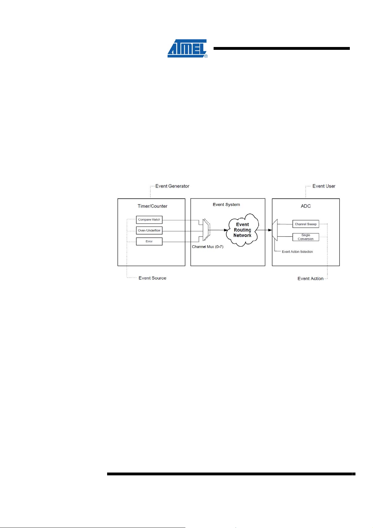
The figure below illustrates the Event System. The figure shows the different parts
that makes it operate; the event sources, the channel MUX’s and the event action
selection in the event user/peripheral.
The figure shows a simplified version with one timer/counter as event generator and
one ADC as an event user. The event channel MUX’s can select one of three
available sources to be routed though the corresponding event channel.
Events can be generated by the following peripherals:
• Timer/Counters (TCxn)
• Real Time counter (RTC)
• Analog to Digital converters (ADCx)
• Analog Comparators (ACx)
• Ports (PORTx)
• System clock (clksys)
Each of these peripherals has several sources for events. Examples of sources are
timer/counter overflow, pin change on a port or A/D conversion completed. The full list
of available event sources is shown in the register description for the Event System in
the Atmel XMEGA A manual.
The channel multiplexers (MUX) selects what source is routed into each of the 8
event system channels available. Each event system channel allows one source that
generates events to that channel. The EVSYS.CHxMUX registers controls the event
source for each channel.
2
AVR1504
8313A-AVR-06/10
Page 3

http://www.BDTIC.com/ATMEL
Events can be used by the following peripherals:
• Timer/Counters
• Analog to Digital Converters
• Digital to Analog Converters
• Direct Memory Access Controller (DMAC)
Usage of events is controlled on the individual peripherals. Configuration registers on
the individual peripheral allows you to select what event channel to use as input and
what the event action is for that channel. Several peripherals can be using the same
event channel as input. This is convenient for allowing several actions start at the
same time.
For example: starting input capture of a Timer/Counter at the same time as starting a
conversion in an ADC. The available event actions are shown in the register
description for each peripheral.
AVR1504
8313A-AVR-06/10
3
Page 4

3 Overview
http://www.BDTIC.com/ATMEL
Here is a short overview of the tasks in this training:
Task 1: 32-bi t Timer/Counter
This task shows the basic Event System setup with event user and event generator
and how this can be used for making a 32-bit timer.
Task 2: Input capture with filtering
Input capture with a Timer/Counter is controlled with events in Atmel XMEGA, and
this task shows you how flexible this is.
Task 3: Synchronized triggering
More than one peripheral can use events from one event channel, and this can be
used to synchronize event actions in the peripherals.
Task 4: Manually generating events
Events can be generated from software, and this task gives you a basic example on
how to do this.
GOOD LUCK!
4
AVR1504
8313A-AVR-06/10
Page 5
4 Task 1: 32-bit Timer/Counter
http://www.BDTIC.com/ATMEL
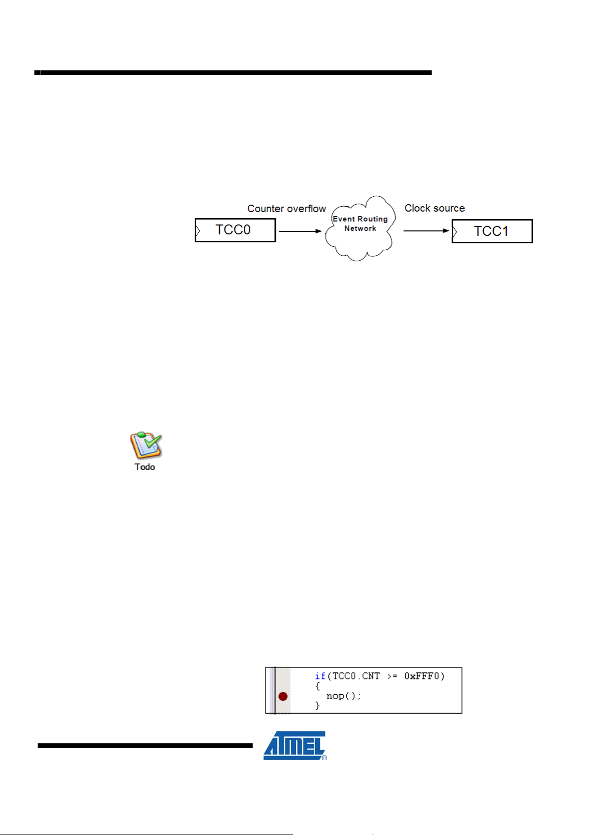
By using the overflow event from one Timer/Counter as the clock input/source to
another Timer/Counter, it is possible to use the Event System for making a 32-bit
Timer/Counter. In this setup it is also possible to do input capture in order to have 32bit input capture. In the Timer/Counter hands-on session we use the Peripheral Clock
as input to the timer/counter TCC0, and the event system will be used as input to
timer/counter TCC1. The following figure shows this conceptually:
The AVR1001 – using the Atmel XMEGA event system application note contains a
code example on how to implement a 32-bit Timer/Counter with input capture.
The goal for this task is that you:
• Understand the basics of using the Event System, and how to configure an event
channel
• Know how to use an event channel in a peripheral module
• Understand how to use an event channel to clock a timer
TASK:
AVR1504
1. Locate the Atmel XMEGA-EventSystem folder and open the
32bitTimerCounter.aps project file in AVR Studio
2. Spend some time to understand the code, how it works, and ensure you know the
basics of how the Event System is set up
3. Build the project, ensure there are no errors (you can ignore the warning) and start
a debug session
4. Run the code, and you will see that the LEDs are counting upwards with the clock
tick rate of the most significant TC which is clocked from the event system
5. Break and place a breakpoint as indicated below:
5
8313A-AVR-06/10
Page 6

6. Run the code again and see that it breaks when the least significant timer is close
http://www.BDTIC.com/ATMEL
to overflow. If you single step a few times, the timer will overflow, and you will see
that the LED is counting. If you expand the IO view for TCC1, you can see how
CNT increase when TCC0 overflows
7. If you wish to write some code in this task, you can add code to make a 48- or 64-
bit timer ☺
6
AVR1504
8313A-AVR-06/10
Page 7

5 Task 2: Input Capture with Filtering
http://www.BDTIC.com/ATMEL
In Task 1 we used the Event System to trigger events that were the clock source to a
Timer/Counter (TC). In general, a peripheral may perform different actions when
receiving an event. For instance, for the TC, see the timer event action list in the
CTRLD register shown in the register description of the Timer counter in the Atmel
XMEGA A Manual. Take a look at this table to understand what event actions the
timer can use.
By having the Event System able to trigger input capture is much more flexible than
having one or a few capture pins. Because a pin change on any I/O pin can be used
to generate an event, this means that any I/O pin can be used as an input capture
pin.
In fact, any event can trigger an input capture, not just pin changes. In this task we
will stick to the basics and we will use a pin change event to do input capture. To
make this work we need to configure the following:
• Timer TCC0 to perform input capture on capture channel A (CCA) when getting an
event on channel 0
• Event System routing to route PORTE pin 0 events into event channel 0
• Input sensing on PORTE pin 0 to specify if rising edge, falling edge, both edges or
the level of the pin generates events
AVR1504
The goal for this task is that you:
• Understand how to set up input capture using a timer and the Event System
• Know how filtering on the I/O pins is handled by the Event System
TASK:
1. Locate the InputCapture.aps Atmel AVR Studio project file. Open the task2.c file
and familiarize yourself with the code
2. The code is almost done, but you need to configure the event channel 0 MUX to
use pin 0 of PORTF as input to this event channel. If you need help, see how this
is done in Task 1
3. Build the project, ensure there are no errors (you may ignore the warning) and
open the debug file in AVR Studio
4. Run the code; press the switch a few times
5. Each press will generate an event (or in fact two events) that trigger the input
capture. The capture values are continuously read and output to the LEDs
Why does each press generate two events?
8313A-AVR-06/10
7
Page 8

6. Let’s look at the Error flag. The Error flag is set when there is a buffer overflow for
http://www.BDTIC.com/ATMEL
the input captures registers in the TC. You can study Section 14.5 (double
buffering) in the Atmel XMEGA A manual to see how this works
7. Add error_count to the Watch window so you can follow the number of overflow
errors
8. Run the code, press the switch many times with short intervals, break and see if
any errors occurred. You should be able to generate some
9. We are using noise from the buttons to generate quickly enough to get a buffer
overflow. If it is difficult to press the switch to generate overflow, you can add a
delay (for example _delay_ms(200); ) in the while(1) loop so the CCA register is
not read that often
10. While the debug session is still stopped, locate the Event System in the IO view
and expand it to see the current configuration
11. The first instance of the Digital Filter, represents the filter for event channel 0
8
AVR1504
8313A-AVR-06/10
Page 9

http://www.BDTIC.com/ATMEL
12. Change the digital filter to set how many pin change events must be sampled by
the peripheral clock before the event is passed through
13. Run the code again, press the switch and see how the different filter value is able
to reduce the error_count
AVR1504
8313A-AVR-06/10
9
Page 10

6 Task 3: Synchronized Triggering
http://www.BDTIC.com/ATMEL
It is possible to let different peripherals use the same event channel as input, and by
doing this several peripherals can use the same event. This can for example be used
to synchronize actions. Here are a few examples where this is useful:
• For doing an input capture and start an ADC conversion at the same time, in order
to give the conversion a time stamp
• For starting conversions on two ADCs at the same time
• Other combinations of ADC, DAC, Timer/counter and DMA
In this task we are going to keep it simple and use the Event System to initiate input
capture on 3 timers (TCC0, TCD0 and TCE0) simultaneously. Timer/counter TCF0
overflow is used as the event trigger source (generator).
The goal for this task is that you:
• Are able to configure the Event System
• Understand synchronized Triggering
TASK:
1. Locate the folder for Task 3 and open the SynchronizedTriggering.aps project.
Look at the task3.c file and familiarize yourself with the code
2. The code is almost complete, but we need to do some changes:
a. Add code that sets up the timer/counter TCD0 and TCE0 in the same
way as TCC0
b. Set up overflow of timer/counter TCF0 as input to event channel 0
c. Build the project, ensure there are no errors, and start debugging in
Atmel AVR Studio
3. Let’s run the code and make sure that the event is triggered as expected, and that
the input capture happens
4. Break the execution, and place a breakpoint as indicated below:
10
AVR1504
8313A-AVR-06/10
Page 11

http://www.BDTIC.com/ATMEL
5. Add a watch on the capture_values variable by right clicking on the variable and
selecting “Add watch : “capture_valu es”. This array contains capture values from
all three timers
6. Run the code and observe that the
You can notice that all the capture values are almost the same. Why are they not
exactly the same?
If you have time, add code to set all the count (CNT) values of the timer/counter to
zero before the while loop. Are the capture values the same now? Why?
capture_values variable gets updated
AVR1504
8313A-AVR-06/10
11
Page 12

7 Task 4: Manually Generating Events
http://www.BDTIC.com/ATMEL
Events can be generated manually from software. This is done by STROBE registers
or by accessing the registers directly during on-chip debugging. Writing the STROBE
register triggers the operation.
It is possible to generate events on several channels at the same time by writing to
several bit locations at once. This can be useful for synchronizing event actions, for
on-chip debug or using events to keep track of program execution status.
Manually generated events last for one clock cycle and will overwrite events from
other event sources during that clock cycle.
The goal for this task is that you:
• Know how to generate events from software
• Understand when generating events from software can be useful
• Know how to synchronize several timer/counters
TASK:
1. Locate the ManuallyGeneratingEvent.aps project and open it in Atmel AVR Studio
2. Open the task4.c file and familiarize yourself with the code. The code is similar to
task3, but notice that timer/counter TCC0, TCD0 and TCE0 are now running with a
clock prescaler/divider of 1 (same speed as the CPU). In addition the
timer/counters are now configured to RESTART when an event is received
3. Build the project, ensure there are no errors, and start debugging the project
4. Place a breakpoint in the main loop
5. Add a watch to
6. Notice that the
happens on the exact clock cycle. This is like in Task 3 because the timers are
started at different clock cycles
capture_values so you can keep track of the compare values
capture_values are now different values even if the input capture
12
AVR1504
8313A-AVR-06/10
Page 13

http://www.BDTIC.com/ATMEL
7. The code is almost done, but you need to add code to generate events from
software on event channel 0
8. Place a breakpoint in the code so you can single step after the software events are
generated
9. Run the code and ensure that it stops at the breakpoint
10. Open the Event System in the IO view and single step to see that the STROBE
register is being written, and cleared again in the next cycle
AVR1504
8 Summary
11. Use “Run to cursor” to see that the compare_values are updated with new values
after the event triggered the input capture. Notice that all the timers are now
perfectly synchronized
12. The STROBE register can be written during on-chip debug, for example by using
the IO view to set the bits. The bits that are written will be cleared in the next cycle.
You can test this, but keep in mind that the capture values for the timer are not
kept if the buffer is full. Instead you will get an error
In this hands-on we have learned how the Event System operates, how to configure it
and we have shown you potential uses for the Event System.
8313A-AVR-06/10
13
Page 14

9 Resources
http://www.BDTIC.com/ATMEL
• Atmel XMEGA Manual and Datasheets
o http://www.atmel.com/xmega
• Atmel AVR Studio with help files
o http://www.atmel.com/products/AVR/
• WINAVR GCC compiler
o http://winavr.sourceforge.net/
• Atmel IAR Embedded Workbench
o http://www.iar.com/
10 Atmel Technical Support Center
Atmel has several support channels available:
®
compiler
o Web portal: http://support.atmel.no/
o Email: avr@atmel.com
o Email: avr32@atmel.com
Please register on the web portal to gain access to the following services:
o Access to a rich FAQ database
o Easy submission of technical support requests
o History of all your past support requests
o Register to receive Atmel microcontrollers’ newsletters
o Get information about available trainings and training material
All Atmel AVR products
All Atmel microcontrollers
All 32-bit AVR products
14
AVR1504
8313A-AVR-06/10
Page 15

http://www.BDTIC.com/ATMEL
Disclaimer
Headquarters International
Atmel Corporation
2325 Orchard Parkway
San Jose, CA 95131
USA
Tel: 1(408) 441-0311
Fax: 1(408) 487-2600
Atmel Asia
Unit 1-5 & 16, 19/F
BEA Tower, Millennium City 5
418 Kwun Tong Road
Kwun Tong, Kowloon
Hong Kong
Tel: (852) 2245-6100
Fax: (852) 2722-1369
Atmel Europe
Le Krebs
8, Rue Jean-Pierre Timbaud
BP 309
78054 Saint-Quentin-enYvelines Cedex
France
Tel: (33) 1-30-60-70-00
Fax: (33) 1-30-60-71-11
Atmel Japan
9F, Tonetsu Shinkawa Bldg.
1-24-8 Shinkawa
Chuo-ku, Tokyo 104-0033
Japan
Tel: (81) 3-3523-3551
Fax: (81) 3-3523-7581
Product Contact
Web Site
www.atmel.com
Disclaimer: The information in this document is provided in connection with Atmel products. No license, express or implied, by estoppel or otherwise, to any
intellectual property right is granted by this document or in connection with the sale of Atmel products. EXCEPT AS SET FORTH IN ATMEL’S TERMS AND
CONDITIONS OF SALE LOCATED ON ATMEL’S WEB SITE, ATMEL ASSUMES NO LIABILITY WHATSOEVER AND DISCLAIMS ANY EXPRESS, IMPLIED
OR STATUTORY WARRANTY RELATING TO ITS PRODUCTS INCLUDING, BUT NOT LIMITED TO, THE IMPLIED WARRANTY OF MERCHANTABILITY,
FITNESS FOR A PARTICULAR PURPOSE, OR NON-INFRINGEMENT. IN NO EVENT SHALL ATMEL BE LIABLE FOR ANY DIRECT, INDIRECT,
CONSEQUENTIAL, PUNITIVE, SPECIAL OR INCIDENTAL DAMAGES (INCLUDING, WITHOUT LIMITATION, DAMAGES FOR LOSS OF PROFITS,
BUSINESS INTERRUPTION, OR LOSS OF INFORMATION) ARISING OUT OF THE USE OR INABILITY TO USE THIS DOCUMENT, EVEN IF ATMEL HAS
BEEN ADVISED OF THE POSSIBILITY OF SUCH DAMAGES. Atmel makes no representations or warranties with respect to the accuracy or completeness of the
contents of this document and reserves the right to make changes to specifications and product descriptions at any time without notice. Atmel does not make any
commitment to update the information contained herein. Unless specifically provided otherwise, Atmel products are not suitable for, and shall not be used in,
automotive applications. Atmel’s products are not intended, authorized, or warranted for use as components in applications intended to support or sustain life.
© 2010 Atmel Corporation. All rights reserved. Atmel®, Atmel logo and combinations thereof, AVR®, AVR® logo, AVR Studio® and others, are
the registered trademarks, XMEGA™ and others are trademarks of Atmel Corporation or its subsidiaries. Other terms and product names may
be trademarks of others.
Literature Request
www.atmel.com/literature
Technical Support
avr@atmel.com
Sales Contact
www.atmel.com/contacts
8313A-AVR-06/10
 Loading...