

Page 1

http://www.BDTIC.com/ATMEL
AVR1503: Xplain training - XMEGA
Programmable Multi Interrupt Controller
Prerequisites
• Required knowledge
Completed AVR1500 XMEGA™ Basics training
• Software prerequisites
Atmel
WinAVR/GCC 20100110 or later
• Hardware prerequisites
Xplain evaluation board
JTAGICE mkII
• Estimated completion time:
1.5 hours
1 Introduction
Atmel XMEGA has an advanced Programmable Multi-level Interrupt Controller
(PMIC). The PMIC allows control over interrupt priorities and scheduling of
interrupts.
In this hand-on we will learn more about the Atmel XMEGA Programmable
Interrupt Controller.
®
AVR® Studio® 4.18 SP2 or later
8-bit
Microcontrollers
Application Note
Rev. 8312A-AVR-06/10
Page 2

2 Introduction to the PMIC
http://www.BDTIC.com/ATMEL
Atmel XMEGA has a Programmable Multi-level Interrupt Controller (PMIC). All
peripherals can define three different priority levels for interrupts; high, medium or
low. Medium level interrupts may interrupt low level interrupt service routines. High
level interrupts may interrupt both low and medium level interrupt service routines.
Low level interrupts have an optional Round Robin scheme to make sure all interrupts
are serviced within a certain amount of time.
3 Overview
This training session covers the basic features of the Atmel XMEGA Programmable
Multi-level Interrupt Controller (PMIC). The goal of this training is to get you started
with simple interrupt handlers, using the priority levels and scheduling features of the
PMIC to create robust interrupt controlled applications.
Here is a short overview of the tasks in this training:
Task 1: Overflow Interrupt
This task shows how to create a simple interrupt handler for a timer overflow interrupt.
Task 2: Interrupt Levels
This task shows how different interrupt levels interact.
Task 3: Round Robin
This task shows how interrupt priorities can cause starvation of interrupts with lower
priority, and how the Round Robin scheduling feature can be used to prevent
starvation.
GOOD LUCK!
2
AVR1503
8312A-AVR-06/10
Page 3
4 Task 1: Overflow Interrupt
http://www.BDTIC.com/ATMEL
Blinking LEDs are fun, but interrupt controlled blinking LEDs are more fun! This task
shows the necessary steps to configure a timer and enable its overflow interrupt to
blink an LED for us.
The goal for this task is that you know how to:
• Write an interrupt handler function, and associate it with the corresponding
interrupt vector
• Enable an interrupt source such as a timer’s overflow interrupt, and select the
interrupt level
• Configure the PMIC to let through interrupts of a certain level, and to enable
interrupts globally
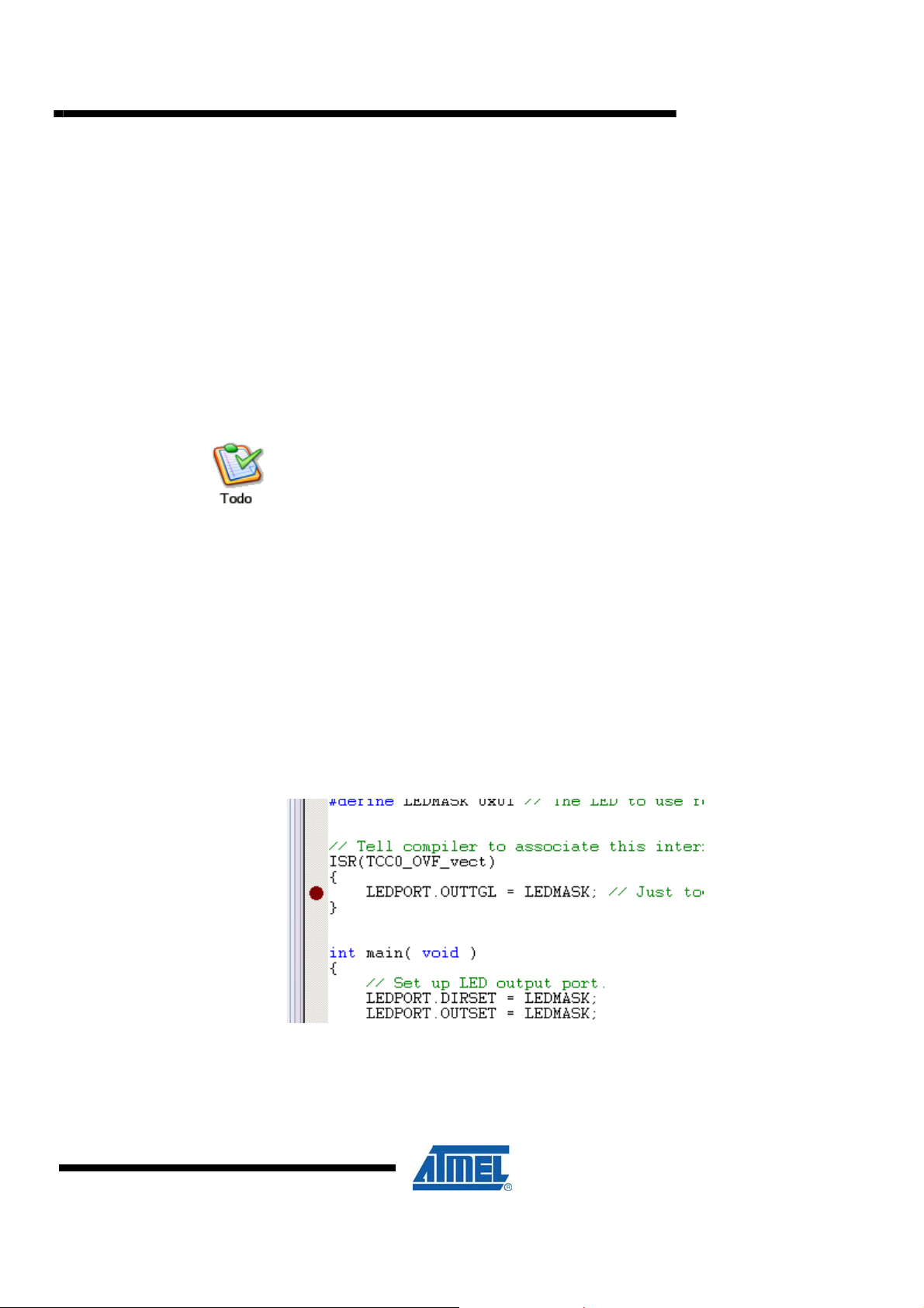
TASK:
1. Locate the XMEGA-PMIC folder, find the Task 1 folder and open the
OverflowInterrupt.aps project file in Atmel AVR Studio
2. Look through the code and ensure you understand how things are set up
3. Notice how easy it is to change LEDPORT and LEDMASK definitions, if you want
another LED port and/or other LEDs than the default one
4. Build the project and start a debug session (click on the Play icon) in AVR Studio
5. Place a breakpoint (F9) inside the interrupt handler, run the code (F5) and observe
it stopping at the breakpoint
AVR1503
6. Remove the breakpoint (F9 again) and run the code to see the LED blink
7. Feel free to change interrupt levels, and timer speed. Recompile and run again
8312A-AVR-06/10
3
Page 4

5 Task 2: Interrupt Levels
http://www.BDTIC.com/ATMEL
If an interrupt handler is badly designed and ends up in an endless loop, for instance
by doing something stupid like waiting for a switch to be pressed by the user, it halts
the entire processor, right? Not quite so with Atmel XMEGA... This task shows how
different interrupt levels interact, and how lower level interrupts can easily be
interrupted by higher level ones.
The goal for this task is that you know how to:
• Implement several interrupt handlers, and assign different levels to the interrupt
sources
• Enable several interrupt levels in the PMIC
• Make code that utilizes nested interrupts
TASK:
1. Locate the XMEGA-PMIC folder, find the Task 2 folder and open the
InterruptLevels.aps project file in Atmel AVR Studio
2. Look through the code and ensure you understand how things are set up
3. Build the project and start a debug session (click on the Play icon) in AVR Studio
The code sets up three different interrupt service routines (ISR) with different priority
levels. Each ISR blinks a LED, and does not return as long as the corresponding
switch is being pressed.
4
4. Run the code (press F5) to see the code blink the three LEDs. Press the switches
to block one of the interrupts and observe higher level interrupts are still running.
Also observe that lower level interrupts are blocked
5. Change the interrupt levels. Recompile and run again
AVR1503
8312A-AVR-06/10
Page 5

6 Task 3: Round Robin
http://www.BDTIC.com/ATMEL
When several interrupts are assigned the same interrupt level, the interrupt vector
number decides the priority. Lower numbers first. What happens if an interrupt takes
so much CPU time that interrupts with lower priority never gets to run? Well, they
starve… unless you enable the Round Robin scheduling scheme of the PMIC. The
last interrupt vector that got CPU time will have the lower priority. This task shows
how to use the Round Robin scheme to allow two interrupts to execute, even if one of
them would take almost 100% CPU time. Note that Round Robin scheduling is only
available for low level interrupts.
The goal for this task is that you know how to:
• Turn on and off Round Robin scheduling for low level interrupts
• Know how to prevent one high rate interrupt from starving another low rate
interrupt
TASK:
1. Locate the XMEGA-PMIC folder, find the Task 3 folder and open the
RoundRobin.aps project file in Atmel AVR Studio
2. Look through the code and ensure you understand how things are set up
3. Build the project and start a debug session in AVR Studio
4. Run the code (press F5) to see the code blink one LED while the other does not
get CPU time to blink. Press the switch SW1 to enable Round Robin scheduling
and SW0 to turn Round Robin scheduling off. When enabled observe the other
LED also getting CPU time to blink
5. Comment away the PMIC.INTPRI = 0; line, recompile, run
AVR1503
What happens the next time you release the switch to turn off Round Robin
scheduling again, and why?
7 Summary
In this training we have looked at the programmable interrupt controller (PMIC). We
have seen how you can set up different priorities for interrupts (low, medium, high).
We have also seen that the low level interrupts can have different priority schemes
(Round Robin or fixed) and what effect this has on the interrupts.
8312A-AVR-06/10
5
Page 6

8 Resources
http://www.BDTIC.com/ATMEL
• Atmel XMEGA Manual and Datasheets
o http://www.atmel.com/xmega
• Atmel AVR Studio with help files
o http://www.atmel.com/products/AVR/
• WINAVR GCC compiler
o http://winavr.sourceforge.net/
• Atmel IAR Embedded Workbench
o http://www.iar.com/
9 Atmel Technical Support Center
Atmel has several support channels available:
®
compiler
• Web portal: http://support.atmel.no/
• Email: avr@atmel.com
• Email: avr32@atmel.com
Please register on the web portal to gain access to the following services:
• Access to a rich FAQ database
• Easy submission of technical support requests
• History of all your past support requests
• Register to receive Atmel microcontrollers’ newsletters
• Get information about available trainings and training material
All Atmel AVR products
All Atmel microcontrollers
All 32-bit AVR products
6
AVR1503
8312A-AVR-06/10
Page 7

http://www.BDTIC.com/ATMEL
Disclaimer
Headquarters International
Atmel Corporation
2325 Orchard Parkway
San Jose, CA 95131
USA
Tel: 1(408) 441-0311
Fax: 1(408) 487-2600
Atmel Asia
Unit 1-5 & 16, 19/F
BEA Tower, Millennium City 5
418 Kwun Tong Road
Kwun Tong, Kowloon
Hong Kong
Tel: (852) 2245-6100
Fax: (852) 2722-1369
Atmel Europe
Le Krebs
8, Rue Jean-Pierre Timbaud
BP 309
78054 Saint-Quentin-enYvelines Cedex
France
Tel: (33) 1-30-60-70-00
Fax: (33) 1-30-60-71-11
Atmel Japan
9F, Tonetsu Shinkawa Bldg.
1-24-8 Shinkawa
Chuo-ku, Tokyo 104-0033
Japan
Tel: (81) 3-3523-3551
Fax: (81) 3-3523-7581
Product Contact
Web Site
www.atmel.com
Disclaimer: The information in this document is provided in connection with Atmel products. No license, express or implied, by estoppel or otherwise, to any
intellectual property right is granted by this document or in connection with the sale of Atmel products. EXCEPT AS SET FORTH IN ATMEL’S TERMS AND
CONDITIONS OF SALE LOCATED ON ATMEL’S WEB SITE, ATMEL ASSUMES NO LIABILITY WHATSOEVER AND DISCLAIMS ANY EXPRESS, IMPLIED
OR STATUTORY WARRANTY RELATING TO ITS PRODUCTS INCLUDING, BUT NOT LIMITED TO, THE IMPLIED WARRANTY OF MERCHANTABILITY,
FITNESS FOR A PARTICULAR PURPOSE, OR NON-INFRINGEMENT. IN NO EVENT SHALL ATMEL BE LIABLE FOR ANY DIRECT, INDIRECT,
CONSEQUENTIAL, PUNITIVE, SPECIAL OR INCIDENTAL DAMAGES (INCLUDING, WITHOUT LIMITATION, DAMAGES FOR LOSS OF PROFITS,
BUSINESS INTERRUPTION, OR LOSS OF INFORMATION) ARISING OUT OF THE USE OR INABILITY TO USE THIS DOCUMENT, EVEN IF ATMEL HAS
BEEN ADVISED OF THE POSSIBILITY OF SUCH DAMAGES. Atmel makes no representations or warranties with respect to the accuracy or completeness of the
contents of this document and reserves the right to make changes to specifications and product descriptions at any time without notice. Atmel does not make any
commitment to update the information contained herein. Unless specifically provided otherwise, Atmel products are not suitable for, and shall not be used in,
automotive applications. Atmel’s products are not intended, authorized, or warranted for use as components in applications intended to support or sustain life.
© 2010 Atmel Corporation. All rights reserved. Atmel®, Atmel logo and combinations thereof, AVR®, AVR® logo, AVR Studio® and others, are
the registered trademarks, XMEGA™ and others are trademarks of Atmel Corporation or its subsidiaries. Other terms and product names may
be trademarks of others.
Literature Request
www.atmel.com/literature
Technical Support
avr@atmel.com
Sales Contact
www.atmel.com/contacts
8312A-AVR-06/10
 Loading...